CONTROLS ROSS SAFETY-RELATED PRODUCTS
|
|
|
- Hollie Lewis
- 5 years ago
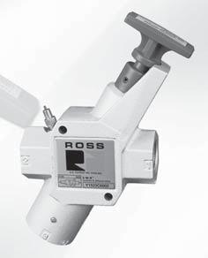
- Views:
Transcription


1 CONTROLS ROSS SAETY-RELATED PRODUCTS


2 Energy Isolation Lockout and Lockout with Soft-Start Valves Safety Exhaust Control Reliable Energy Isolation Double Valves Safety Exhaust & Safety Exhaust/Energy Isolation Sensing Valves Safe Cylinder Return Control Reliable Double Valves Cylinder Stop and Load Holding Pilot Operating Check Valves Explosion-Proof Valves AIR-USE low Diffusers
3 Contents Page Energy Isolation Lockout and Lockout with Soft-Start Valves Manual Lockout Valves 5 Series Piloted Valves with Manual Lockout 7 Series Soft-Start Valves 9 & 7 Series Modular Lockout Valves 5 Series Manual Lockout with Soft-Start Valves 5 & 7 Series. -.5 Safety Exhaust Control Reliable Energy Isolation Double Valves Designed for External Monitoring M5 & RSe Series With Dynamic Monitoring & Memory DM Series C & E With Dynamic Monitoring and Automatic Reset DM Series C & E Air Entry Packages. -.5 Safety Exhaust & Safety Exhaust/Energy Isolation Sensing Valves SV7 Series SV7 Series with Manual Lockout L-O-X. -.0 Air Entry Packages Safe Cylinder Return Control Reliable Double Valves RSe Series CROSSMIRROR 77 SERIES. -.5 CROSSMIRROR CM Series Safe Cylinder Stop and Load Holding Pilot Operating Check Valves CROSSCHECK Series With Sensing SV7 Series Right-Angle Valves 9 Series 7 Series Explosion-Proof Double and Single Valves ATEX Certified TUV SUD Control Reliable Double Valves DM Series C 7 Series Poppet Series Poppet for High and Low Temperature ISO Minimize Hose Whip AIR-USE low Diffusers 9 Series Cautions and Warranty Compatible Lubricants Cautions and Warnings Inside Cover Rev. 0/0/7 0.


4


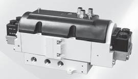
5 CONTROLS ENERGY ISOLATION LOCKOUT & EXHAUST L-O-X, SOT-START EEZ-ON VALVES 5, 9 & 7 SERIES
6 MANUAL LOCKOUT & EXHAUST L-O-X VALVES KEY EATURES luorocarbon slipper seals for easy shifting, even after long periods of inactivity Easily identified by yellow body with red handle Integrated sensing port for pressure verification Lockable only in the O position Has a full size exhaust port (equal to or larger than supply) Simple push/pull of the large handle provides positive direct manual operation MANUAL LOCKOUT L-O-X VALVES WITH SOT-START EEZ-ON KEY EATURES Easily identified by blue handle Gradual re-application of pneumatic pressure prevents rapid equipment movement at startup Lockable only in the O position Has a full size exhaust port (equal to or larger than supply) Positive action ( positions only) Simple push/pull of the large blue handle provides positive direct manual operation Integrated sensing port for pressure verification AVAILALE PORT SIZES UNCTIONS VALVE TYPE VALVE SERIES / /8 / / ¼ ½ ½ / / Max low (Cv) Solenoid Control Pressure Control Page Manual Lockout & Exhaust L-O-X Valves Slim-Line Modular Classic High-Capacity L-O-X Stainless Steel Stainless Steel with Integrated ilter/regulator RCO Piloted Valves with Manual Lockout L-O-X Control Soft-Start EEZ-ON Valves Right-Angle Manual Lockout L-O-X Valves with Soft-Start EEZ-ON Operation Modular Classic Piloted Valves with Manual Lockout L-O-X & Soft-Start EEZ-ON Operation Manual Pilot Controlled Solenoid Pilot Controlled 7 0.5
7 Manual Lockout & Exhaust L-O-X Valves Slim-Line Energy Isolation 5 Series -Way -Position Valve Size C Valve Model Number* V, - - Weight lb (kg) / /8 Y5D (0.) /8 /8 Y5D (0.) * NPT port threads. or SPP threads, insert a D after Y to the model number, e.g., YD5D00. 0 Valve Dimensions inches (mm).5 (57.) 0.8(0.6).5 (5.6) Ø0. (8.6).56 (5.8) 0.99 (5.) 0. (8.6).80 (5.7) 7.08 (79.8).00 (76.) Ø0.8 (7.).9 (0.).5 (.8).9 (8.8).00 (5.).50 (8.).5 (8.9) ACCESSORIES & OPTIONS Silencers Size Thread Type Model Number Avg. C V Male - NPT 5500A0.7 /8 Male - SPT D5500A0.7 Pressure Range: 0 to 00 psig (0 to 0.7 bar) maximum. low Media: iltered air. VALVE OPERATION Pressure Switches Connection Type Model Number* Threads EN orm A 586A86 /8 NPT M 5A0 /8 NPT *Pressure switch closes on falling pressure of 5 psig (0. bar). Pop-Up Indicator Model Number** 988A0 ** /8 NPT port threads. Multiple Lockout Device Model Number 56A0 EN Connector Pinout Open Common Closed Ground M Connector Pinout Pin Open Pin Common Pin Not Used Pin Closed Valved Closed When the red handle is pushed inward, the flow of supply air is blocked and downstream air is exhausted via the exhaust port. While servicing or maintaining machinery, the L-O-X valve should be padlocked in this position to prevent the handle from being pulled outward inadvertently where potential for human injury exists. Valve Open When the red handle is pulled outward supply air flows freely from inlet to outlet and flow to exhaust is blocked. A detent keeps the handle in the open position. If a system requires gradual buildup of downstream pressure, see manual L-O-X valves with EEZ-ON operation. STANDARD SPECIICATIONS (for valves on this page): Construction: Spool. Mounting Type: In-Line. Ambient/Media Temperature: 0 to 75 ( to 80 C). low Media: iltered air. Inlet Pressure: 0 to 5 psig (0 to 0 bar). Lock Hole Diameter: 0.7 inch (7.0 mm). Length of Hole: 0. inch (0.9 mm). Rev. 0/0/7.
8 Manual Lockout & Exhaust L-O-X Valves Modular Energy Isolation 5 Series -Way -Position Valve, Size C V Valve Model Number*, - - Weight lb (kg) / / Y5A (0.8) 0 /8 / Y5A (0.8) / / Y5A (0.8) / / Y5A (0.8) * NPT port threads. or SPP threads, insert a D after Y to the model number, e.g., YD5A00. Valve Dimensions inches (mm).90 (7.7).0 (0.9). (.8).05 (0.9).5 (5.6) 0.80 (0.) R 0.5 (.8). (79.8).98 (6.5) ACCESSORIES & OPTIONS Silencers Size Thread Type Model Number Avg. C V Male - NPT 5500A500.5 / Male - SPT D5500A500.5 Pressure Range: 0 to 00 psig (0 to 0.7 bar) maximum. low Media: iltered air. Pressure Switches Connection Type Model Number* Threads EN orm A 586A86 /8 NPT M 5A0 /8 NPT *Pressure switch closes on falling pressure of 5 psig (0. bar). Pop-Up Indicator Model Number** 988A0 ** /8 NPT port threads. EN Connector Pinout Open Common Closed Ground M Connector Pinout Pin Open Pin Common Pin Not Used Pin Closed Multiple Lockout Device Model Number 56A0 VALVE OPERATION Valved Closed When the red handle is pushed inward, the flow of supply air is blocked and downstream air is exhausted via the exhaust port. While servicing or maintaining machinery, the L-O-X valve should be padlocked in this position to prevent the handle from being pulled outward inadvertently where potential for human injury exists. Valve Open When the red handle is pulled outward supply air flows freely from inlet to outlet and flow to exhaust is blocked. A detent keeps the handle in the open position. If a system requires gradual buildup of downstream pressure, see manual L-O-X valves with EEZ-ON operation. STANDARD SPECIICATIONS (for valves on this page): Construction: Spool. Mounting Type: Modular, In-Line. Ambient/Media Temperature: 0 to 75 ( to 80 C). low Media: iltered air. Inlet Pressure: 0 to 00 psig (0 to bar). Lock Hole Diameter: 0.7 inch (7.0 mm). Length of Hole: 0. inch (0.9 mm).. 07, ROSS CONTROLS. All Rights Reserved. Rev. 0/0/7
 ¼ Y5C600 6.56 9.5.5 (.) ¼ ¼ Y5C70 9.5 9.7.5 (.) *NPT port threads. or SPP threads, insert a D after Y to the model number, e.g., YD5D00.")
9 Manual Lockout & Exhaust L-O-X Valves Classic Energy Isolation 5 Series -Way -Position Valve Size C V ody Size Valve Model Number*, - - Weight lb (kg) /8 / / Y5C (0.7) / / / Y5C (0.7) / / / Y5C (0.7 / ¼ Y5C (.) ¼ Y5C (.) ¼ ¼ Y5C (.) *NPT port threads. or SPP threads, insert a D after Y to the model number, e.g., YD5D00. 0 Valve Dimensions inches (mm) (outlet).6 ().5 () 8.96 (8) (inlet).5 ody Size / (57) ody Size 0. (8).00 (76) (outlet).88 (8).75 () 0. (8).75 (70) 0.76 (7) (inlet).75 (95) (exhaust).6 () 6.6 (68).00 (5) (exhaust) 5.50 (0) 7.7 (96).5 (57) ACCESSORIES & OPTIONS Silencers Size / Thread Type Model Number* Avg. C V Male - NPT 5500A500.5 Male - SPT D5500A500.5 Male - NPT 5500A70 6. ¼ Male - SPT D5500A70 6. Pressure Range: 0 to 00 psig (0 to 0.7 bar) maximum. low Media: iltered air. Pressure Switches Connection Type Model Number* Threads EN orm A 586A86 /8 NPT M 5A0 /8 NPT *Pressure switch closes on falling pressure of 5 psig (0. bar). Pop-Up Indicator Model Number** 988A0 ** /8 NPT port threads. EN Connector Pinout Open Common Closed Ground M Connector Pinout Pin Open Pin Common Pin Not Used Pin Closed Multiple Lockout Device Model Number 56A0 VALVE OPERATION Valved Closed With a short push of the red handle inward, the flow of supply air is blocked and downstream air is exhausted via the exhaust port at the bottom of the valve. The L-O-X valve should be padlocked in this position to prevent the handle from being pulled outward inadvertently where potential for human injury exists or while servicing machinery. Valve Open When the red handle is pulled out, supply air flows freely from inlet to outlet and flow to exhaust is blocked. A detent keeps the handle in the open position. The handle is not designed to be locked in this position, thereby providing for ready shut-off when necessary. If a system requires gradual buildup of downstream pressure, see manual L-O-X valves with EEZ-ON operation. Construction: Spool. Mounting Type: In-Line. Ambient/Media Temperature: 0 to 75 ( to 80 C). STANDARD SPECIICATIONS (for valves on this page): low Media: iltered air. Inlet Pressure: 0 to 00 psig (0 to 0.7 bar). Rev. 0/0/7.5
.87 (7.5).00 (76.).58 (0.).8 (76.) 0.78 (9.) 8.0 (08.) ACCESSORIES & OPTIONS 0.86 (.8).69 (.")
 maximum. low Media: iltered air.")


10 Manual Lockout & Exhaust L-O-X Valves High-Capacity Energy Isolation 5 Series -Way -Position Valve Size C V Valve Model Number*, - - Weight lb (kg) ½ Y5C (.7) Y5C (.7) * NPT port threads. or SPP threads, insert a D after Y to the model number, e.g., YD5C Valve Dimensions inches (mm).87 (7.5).00 (76.).58 (0.).8 (76.) 0.78 (9.) 8.0 (08.) ACCESSORIES & OPTIONS 0.86 (.8).69 (.9) Valves can be padlocked in two locations, at the handle or at the end of the spool. Silencers Size Thread Type Model Number Avg. C V emale - NPT emale - SPT D Pressure Range: 0 to 00 psig (0 to 0.7 bar) maximum. low Media: iltered air. Pressure Switches Connection Type Model Number* Threads EN orm A 586A86 /8 NPT M 5A0 /8 NPT *Pressure switch closes on falling pressure of 5 psig (0. bar). Pop-Up Indicator Model Number** 988A0 ** /8 NPT port threads. Multiple Lockout Device Model Number 56A0 EN Connector Pinout Open Common Closed Ground M Connector Pinout Pin Open Pin Common Pin Not Used Pin Closed VALVE OPERATION Valved Closed With a short push of the red handle inward, the flow of supply air is blocked and downstream air is exhausted via the exhaust port while servicing or maintaining machinery. Padlock the L-O-X valve in this position to prevent the handle from being pulled outward inadvertently to avoid potential for human injury while servicing machinery. Valve Open When the red handle is pulled out, supply air flows freely from inlet to outlet and flow to exhaust is blocked. A detent keeps the handle in the open position. The handle is not designed to be locked in this position, thereby providing for ready shut-off when necessary. If a system requires gradual buildup of downstream pressure, see manual L-O-X valves with EEZ-ON operation. STANDARD SPECIICATIONS (for valves on this page): Construction: Spool. Mounting Type: In-Line. Ambient/Media Temperature: 0 to 75 ( to 80 C). low Media: iltered air. Inlet Pressure: 0 to 00 psig (0 to 0.7 bar). Lock Hole Diameter: 0.7 inch (7.0 mm). Length of Hole: 0. inch (0.9 mm)..6 07, ROSS CONTROLS. All Rights Reserved. Rev. 0/0/7
 / / 500 5.79 6. 6.0 (.7) 0 / 5500.0 7.0 (5.89 5600.0 7.0 (5.89) ½ 5800 9 5 5.0 (5.87) 5900 9 5 5.0 (5.87) * NPT port threads. or SPP threads, add a D prefix to the model number, e.g., D500.")
11 Manual Lockout & Exhaust L-O-X Valves Stainless Steel Energy Isolation 5 Series -Way -Position Valve Size C V Valve Model Number*, - - Weight lb (kg) / / (.70) /8 / (.7) / / (.7) 0 / ( (5.89) ½ (5.87) (5.87) * NPT port threads. or SPP threads, add a D prefix to the model number, e.g., D500. Valve Dimensions inches (mm).0 (5.).5 (.).60 (0.7).6 (59.8) Size / 8.76 Sizes /8 & / (.) 0.7 (65.8).7 (8.).9 (99.6).8 (85.9).5 (89.9).56 (9.7). (08.5).67 (.7).0 (5.).50 (6.5). (79.8).00 (0.6) Sizes / & Sizes ½ &.05 (56.9) 8.5 (70.9) 5.56 (.). (6.) 8. (06.).5 (89.6).5 (89.9).5 (89.9) VALVE OPERATION Valve Closed With a push of the handle inward, the flow of supply air is blocked and downstream air is exhausted via the exhaust port while servicing or maintaining machinery. Padlock the L-O-X valve in this position to prevent the handle from being pulled outward inadvertently to avoid potential for human injury while servicing machinery. Valve Open When the handle is pulled out, supply air flows freely from inlet to outlet and flow to exhaust is blocked. A detent keeps the handle in the open position. The handle is not designed to be locked in this position, thereby providing for ready shut-off when necessary. STANDARD SPECIICATIONS (for valves on this page): Construction: Spool, 6 Stainless Steel. Mounting Type: In-Line. Ambient/Media Temperature: 0 to 75 (- to 80 C). Note: or lower temperature ratings, consult ROSS. low Media: iltered air. Inlet Pressure: 0 to 00 psig (0 to 0.7 bar). Lock Hole Diameter: sizes / thru : 0. inch (8.6 mm). Length of Hole: size /: 0. in (.7 mm). size /: 0.7 in (.9 mm) size and : 0.55 inch (.97 mm). Rev. 0/0/7.7
 7.65 (9.).9 (00).99 (76).")
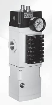
12 Stainless Steel Lockout L-O-X Valves with Integrated ilter/regulator Pneumatic Energy Isolation (LOTO) Air Entry Combination Size C V Model Number*, - - / / RC / / RC / RC0-5 7 Lockout/ilter/Regulator RC0-8 7 Lockout Manual Drain Self-relieving * NPT port threads. or SPP threads, consult ROSS. Dimensions inches (mm) 7.65 (9.).9 (00).99 (76).87 (7) Size / / NPT OUTLET 0. (5.5).9 (00). (80) / NPT EXHAUST. (6.).8 (6).78 (.5). (0.6) / NPT INLET 0. (.0) 8.98 (8).97 (0).9 (8.).99 (76).95 (75) Size / / NPT OUTLET 0. (5.5).9 (00). (80) 0. (.0) x 0. (8.6). (0.5).0 (6.0) / NPT INLET.8 () 5. (7) / NPT EXHAUST SILENCER ITTED Size / / NPT OUTLET 0. (.0) 5.0 (). ().67 (67.8) 0. (.0) x 0. (0.).9 (00). (80) 0. (5.5).7 (.).9 (88.7) / NPT INLET.99 (76).50 (89) 7. (8) 8.6 (9) NPT EXHAUST SILENCER ITTED STANDARD SPECIICATIONS (for valves on this page): Construction: Spool, 6 Stainless Steel. Mounting Type: In-Line. Ambient/Media Temperature: 0 to 75 (- to 80 C). Note: or lower temperature ratings, consult ROSS. low Media: iltered air. Inlet Pressure: 0 to 00 psig (0 to 0.7 bar). Secondary Pressure: 7 to 7 psig (0.5 to bar). Seals: luorocarbon (Viton). Lock Hole Diameter: sizes / thru : 0. inch (8.6 mm). Length of Hole: size /: 0. in (.7 mm). size /: 0.7 in (.9 mm) size and : 0.55 inch (.97 mm)..8 07, ROSS CONTROLS. All Rights Reserved. Rev. 0/0/7
 Air Entry Combination 0. (.0). () 5.0 ().99 (76).50 (89) Size NPT OUTLET 0.")
 NPT EXHAUST SILENCER ITTED Stainless Steel Cabinet for Wash-Down Applications")


13 Stainless Steel Lockout L-O-X Valves with Integrated ilter/regulator Pneumatic Energy Isolation (LOTO) Air Entry Combination 0. (.0). () 5.0 ().99 (76).50 (89) Size NPT OUTLET 0. (.0) 0. (5.5).9 (00). (80).67 (67.8) x 0. (0.).7 (.).9 (88.7) NPT INLET 7. (8) 8.6 (9) NPT EXHAUST SILENCER ITTED Stainless Steel Cabinet for Wash-Down Applications Stainless steel control cabinet includes filter/regulator and Category DM Series valve for Air Entry Control Stainless steel construction, designed for wash-down areas Control cabinet is built with slanted top to avoid pooling Control Reliable Energy Isolation APPLICATIONS: Chemical Processing orestry Mining Pharmaceutical Pulp and Paper Oil and Gas Off-shore Industries Rev. 0/0/7.9

 Weight Avg. C Size Type V NPT Threads SPT Threads A lb (kg) / Male 550000 D550000. 0.56 (.).75 (.5) 0.05 (0.) / Male 550000 D550000.0 0.87 (.).75 (69.")

 Pressure Range: 0 to 7 psig (0 to bar) maximum. low Media: iltered air. Seals: Nitrile.")
14 Accessories & Options Energy Isolation for Stainless Steel 5 Series Stainless Steel Silencers Supplied with a standard pipe thread fitting for attaching directly to the exhaust ports of air-operated equipment» Models with /" & /" port size, all thread forms, have all stainless steel construction» Models with " port size and NPT threads have all stainless steel construction» Models with " port size and SPT threads have standard construction consisting of nickel plated cold rolled steel» Models with " port size, all thread forms, have standard construction consisting of nickel plated cold rolled steel Thread Model Number Dimensions inches (mm) Weight Avg. C Size Type V NPT Threads SPT Threads A lb (kg) / Male D (.).75 (.5) 0.05 (0.) / Male D (.).75 (69.7) 0.5 ( 0.) Male D (.).87 (98.) 0.5 (0.0) Male 5500A900 D5500A (60.) 5.50 (9.7).5 (0.68) Pressure Range: 0 to 00 psig (0 to 0.7 bar) maximum. low Media: iltered air. A Silencers for Stainless Steel L-O-X Air Entry Combinations 6 Stainless Steel sintered element silencers used to protect ports open to the atmosphere. Size Thread Type Model Number Avg. C V Dimensions inches (mm) NPT Threads SP Threads A / Male 5500A005 D5500A (7).50 (8) / Male 5500A005 D5500A ().7 (55 Male 5500A6005 D5500A (6).95 (75) Pressure Range: 0 to 7 psig (0 to bar) maximum. low Media: iltered air. Seals: Nitrile. A Stainless Steel Pressure Switch 6 Stainless Steel ody Nitrile Seals Inlet Size Model Number Weight lb (kg) DPDT (Double-Pole Double-Throw Switch actory preset 5 psi (falling) /8 6A0 0. (.0) NPT port threads. Red/White Circuit Red/Yellow Circuit All Red Green 5 Red/lack 6 Red/lue Pin Configuration Pin COM Pin NC Pin NO Pin 5 NC Pin COM Pin 6 NO /8-7 NPT.5 (9.) 0.6 (5.).6 (0.7) Max. 0.6 (5.).0 (5.) HEX 8.5 (5.9). (8.7) 6.0 (5.) Stainless Steel Visual Indicator 6 Stainless Steel ody, internals and Springs Nitrile Seals Visual Indicator piston, Acetal Visual Indicator assembly, Acetal with acrylic lens Inlet Size Model Number Dimensions inches (mm) A Weight lb (kg) /8 55H0. (59.).00 (5.) 0. (0.) NPT port threads. Hexagon Nut. (0.5) Across lats. (59.).00 (5.).0 07, ROSS CONTROLS. All Rights Reserved. Rev. 0/0/7
 /8 / /8 Y77A07**.6 5..5 (.6) / / /8 Y77A08**. 5..5 (.6) / / Y77A07** 6. 9.. (.9) / / Y77A507** 7.7. (.9) / Y77A608** 8. (.9) ½ ¼ Y77A607** 8.0 (.6) ¼ ½ ¼ Y77A707** 0 8.0 (.6) ½ ½ ¼ Y77A808** 0 8.")
15 Piloted Valves with Manual Lockout L-O-X Control Solenoid Pilot Controlled Energy Isolation 7 Series -Way -Position Valve Size C V ody Size Valve Model Number*, - - Weight lb (kg) / / /8 Y77A07**.5..5 (.6) /8 / /8 Y77A07** (.6) / / /8 Y77A08** (.6) / / Y77A07** (.9) / / Y77A507** 7.7. (.9) / Y77A608** 8. (.9) ½ ¼ Y77A607** 8.0 (.6) ¼ ½ ¼ Y77A707** (.6) ½ ½ ¼ Y77A808** (.6) ½ ½ Y77A807** (7.9) ½ Y77A907** (7.9) ½ ½ Y77A908** (7.9) Y Y * NPT port threads. or SPP threads, insert a D after Y to the model number, e.g., YD77A07W. ** Insert voltage code: W = volts DC; Z = 0-0 volts AC, 50/60 Hz; e.g., Y77A07W. or other voltages, consult ROSS. ACCESSORIES & OPTIONS Silencers Thread Model Number Avg. Size Type NPT Threads SPT Threads C V / Male 5500A00 D5500A00.7 Male 5500A600 D5500A600.6 ½ emale 5500A800 D5500A ½ emale 5500A900 D5500A Pressure Range: 0 to 00 psig (0 to 0.7 bar) maximum. low Media: iltered air. Pressure Switches Connection Type Pop-Up Indicator Model Number* Threads EN orm A 586A86 /8 NPT M 5A0 /8 NPT *Pressure switch closes on falling pressure of 5 psig (0. bar). Model Number** ** /8 NPT port threads. 988A0 EN Connector Pinout Open Common Closed Ground M Connector Pinout Pin Open Pin Common Pin Not Used Pin Closed size / thru size ½ Indicator Light Kits volts DC 86K87-W Kit Number 0-0 volts AC Hz 86K87-Z Indicator Light Multiple Lockout Device Model Number 56A0 STANDARD SPECIICATIONS (for valves on this page): Construction: Poppet. Mounting Type: In-Line. Solenoids: AC or DC power. Rated for continuous duty. Standard Voltages: volts DC; 0-0 volts AC, 50/60 Hz. Power Consumption: 87 VA inrush, 0 VA holding on 50 or 60 Hz; watts on DC. Ambient Temperature: 0 to 0 ( to 50 C). Media Temperature: 0 to 75 ( to 80 C). low Media: iltered air. Inlet Pressure: sizes / to ½: 5 to 50 psig ( to 0 bar). sizes ½ to ½: 0 to 50 psig ( to 0 bar). Pilot Pressure: Must be equal to or greater than inlet pressure. Safety Integrity Level (SIL) Certified by TÜV Rheinland in accordance to IEC 6508 and IEC 65 safety integrity level (SIL ) and EN ISO 89-, PL c or PL d (with application specific diagnosis) in singular application with HT = 0 and SIL and PL e in redundant application with HT. Rev. 0/0/7.
16 Piloted Valves with Manual Lockout L-O-X Control Solenoid Pilot Controlled Energy Isolation 5 Series Valve Dimensions inches (mm) 8. (06) (exhaust) PV (pressure verification). (6).8(7) 0.7 (9) 6.85 (7) ody Size /8 /8 Pilot exhaust port Y- Ø 0. (9) / Electrical conduit port /8 External pilot supply port X- (inlet) { (outlet) on opposite side} 6.9 (6) 8.9 (6) (exhaust) PV (pressure verification).0 (77) 0.6 (5) ody Size / /8 Pilot exhaust port Y- Ø 0. (9) / Electrical conduit port /8 External pilot supply port X- (inlet) { (outlet) on opposite side}.5 (8) 6.5 (66) 6.70 (70) ody Size ¼ ody Size.6 (96) (exhaust) PV (pressure verification) /8 Pilot exhaust port Y- Ø 0.5 () / Electrical conduit port /8 External pilot supply port X-.65 (7) (exhaust) PV (pressure verification) Ø 0.5 () /8 Pilot exhaust port Y- / Electrical conduit port /8 External pilot supply port X-.50 ().5 (9).65 (8) 7.9 (0) (inlet) { (outlet) on opposite side} 6.80 (7) 5.80 (7).5 () 6. (56) 9.0 (9) (inlet) { (outlet) on opposite side} 7. (86) VALVE OPERATION Pilot De-energized With the solenoid pilot de-energized (regardless of the position of the L-O-X handle) the inlet poppet remains closed. The outlet port is connected to the exhaust port so that pressure in the downstream lines is vented to atmosphere. PILOT VALVE Pilot Energized With the solenoid pilot energized and the L-O-X control in the open position, air can flow from inlet to outlet port. The exhaust port is closed. PILOT VALVE PILOT VALVE L-O-X Valve Closed With the handle pushed inward, the L-O-X control is closed, and air to the valve piston is cut off. This allows the inlet poppet to be closed by its spring and the pressure of the inlet air. The outlet is connected to exhaust so downstream pressure is vented.. Rev. 0/0/7
 ½ ¼ Y78A6006 7.0 (.) ¼ ½ ¼ Y78A7006 0 7.0 (.) ½ ½ ¼ Y78A806 0 7.0 (.) ½ ½ Y78A8006 68 70 5. (6.9 ½ Y78A9006 70 70 5. (6.9 ½ ½ Y78A906 70 7 5. (6.9) * NPT port threads.")
 (inlet) { (outlet) on opposite side}.65 (7) (exhaust) PV (pressure verification) Ø 0.5 () ody Size.50 (). (08).5 (9).65 (8) 7.9 (0) 0.8 (). (79).78 (5) 6.80 (7) 5.80 (7).5 () 6. (56) 9.")
17 Piloted Valves with Manual Lockout L-O-X Control Pressure Controlled Energy Isolation 5 Series -Way -Position Valve, Internal Pressure Controlled Size ody C Valve Model Number* V Weight, Size - - lb (kg) ½ ¼ Y78A (.) ¼ ½ ¼ Y78A (.) ½ ½ ¼ Y78A (.) ½ ½ Y78A (6.9 ½ Y78A (6.9 ½ ½ Y78A (6.9) * NPT port threads. or SPP threads, insert a D after Y to the model number, e.g., YD78A6006. Y Valve Dimensions inches (mm) ody Size ¼ (exhaust) PV 8.5 (pressure verification) (6) Ø 0.5 () (inlet) { (outlet) on opposite side}.65 (7) (exhaust) PV (pressure verification) Ø 0.5 () ody Size.50 (). (08).5 (9).65 (8) 7.9 (0) 0.8 (). (79).78 (5) 6.80 (7) 5.80 (7).5 () 6. (56) 9.0 (9) (inlet) { (outlet) on opposite side} 7. (86) ACCESSORIES & OPTIONS Silencers Thread Model Number Avg. Size Type NPT Threads SPT Threads C V ½ emale 5500A800 D5500A ½ emale 5500A900 D5500A Pressure Range: 0 to 00 psig (0 to 0.7 bar) maximum. low Media: iltered air. Pressure Switches Connection Type Model Number* Threads EN orm A 586A86 /8 NPT M 5A0 /8 NPT *Pressure switch closes on falling pressure of 5 psig (0. bar). Pop-Up Indicator Model Number** ** /8 NPT port threads. 988A0 EN Connector Pinout Open Common Closed Ground M Connector Pinout Pin Open Pin Common Pin Not Used Pin Closed size ½ thru size ½ Multiple Lockout Device Model Number 56A0 VALVE OPERATION Valve Closed With a short push of the red handle inward the flow of supply air is blocked and downstream air is exhausted via the exhaust port. Air pressure on the inlet and exhaust poppets produces a large closing force. The L-O-X valve should be padlocked in this position to prevent the handle from being pulled outward inadvertently when potential for human injury exists or servicing machinery. Valve Open With the red handle pulled out, pilot air flows to the top of the actuating piston, causing it to open the inlet poppet. Supply air then flows freely from inlet to outlet, and the exhaust port is blocked. A detent keeps the L-O-X handle in the open position. The handle is designed not to be locked in the open position, thereby allowing for quick shut-off when necessary. STANDARD SPECIICATIONS (for valves on this page): Construction: Poppet. Mounting Type: In-Line. Ambient/Media Temperature: 0 to 75 ( to 80 C). low Media: iltered air. Inlet Pressure: asic Size ¼: 5 to 50 psig ( to 0 bar). asic Size : 0 to 50 psig ( to 0 bar). Pilot Pressure: Must be equal to or greater than inlet pressure. Safety Integrity Level (SIL) Certified by TÜV Rheinland in accordance to IEC 6508 and IEC 65 safety integrity level (SIL ) and EN ISO 89-, PL c or PL d (with application specific diagnosis) in singular application with HT = 0 and SIL and PL e in redundant application with HT. Rev. 0/0/7.
18 Piloted Valves with Manual Lockout L-O-X Control Solenoid Pilot Controlled Energy Isolation L-O-X Series Inch L-O-X Valve for Lockout -Way -Position Valve Size Valve Model, Number - - C V Weight lb (kg) ½ Y900A0896** (5.0) ** Insert voltage code: W = volts DC; Z = 0-0 volts AC, 50/60 Hz; e.g., Y900A0896W. or other voltages, consult ROSS. " NPT Outlet " NPT Inlet Valve Dimensions inches (mm).5 (67).9 (99) 0.0 (5) 9.5 (69).6 (7).5 (67).7 (588) OPTIONS Multiple Lockout Device Model Number 56A0 VALVE OPERATION Pilot De-energized With the solenoid pilot de-energized (regardless of the position of the L-O-X handle) the inlet poppet remains closed. The outlet port is connected to the exhaust port so that pressure in the downstream lines is vented to atmosphere. PILOT VALVE Pilot Energized With the solenoid pilot energized and the L-O-X control in the open position, air can flow from inlet to outlet port. The exhaust port is closed. PILOT VALVE PILOT VALVE L-O-X Valve Closed With the handle pushed inward, the L-O-X control is closed, and air to the valve piston is cut off. This allows the inlet poppet to be closed by its spring and the pressure of the inlet air. The outlet is connected to exhaust so downstream pressure is vented. STANDARD SPECIICATIONS (for valves on this page): Construction: Spool. Mounting Type: In-Line. Solenoids: AC or DC power. Rated for continuous duty. Power Consumption: 87 VA inrush, 0 VA holding on 50 or 60 Hz; watts on DC. Ambient Temperature: 0 to 0 ( to 50 C). Media Temperature: 0 to 75 ( to 80 C). low Media: iltered air; 5 micron filter recommended. Inlet Pressure: 0 to 50 psig ( to 0 bar). Pilot Pressure: Must be equal to or greater than inlet pressure. Threads: NPT.. 07, ROSS CONTROLS. All Rights Reserved. Rev. 0/0/7
 \" NPT Outlet \" NPT Inlet Valve Dimensions inches (mm) 0.9 (78).9 (99) 0.0 (5) 9.5 (69).6 (7) 0.9 (77).")
19 Piloted Valves with Manual Lockout L-O-X Control Pressure Controlled Energy Isolation L-O-X Series Inch L-O-X Valve for Lockout -Way -Position Valve Size Valve Model, Number - - C V Weight lb (kg) ½ Y900A (9.9) " NPT Outlet " NPT Inlet Valve Dimensions inches (mm) 0.9 (78).9 (99) 0.0 (5) 9.5 (69).6 (7) 0.9 (77).6 (588) OPTIONS Multiple Lockout Device Model Number 56A0 VALVE OPERATION Valve Closed With a short push of the red handle inward the flow of supply air is blocked and downstream air is exhausted via the exhaust port. Air pressure on the inlet and exhaust poppets produces a large closing force. The L-O-X valve should be padlocked in this position to prevent the handle from being pulled outward inadvertently when potential for human injury exists or servicing machinery. Valve Open With the red handle pulled out, pilot air flows to the top of the actuating piston, causing it to open the inlet poppet. Supply air then flows freely from inlet to outlet, and the exhaust port is blocked. A detent keeps the L-O-X handle in the open position. The handle is designed not to be locked in the open position, thereby allowing for quick shut-off when necessary. STANDARD SPECIICATIONS (for valves on this page): Construction: Spool. Mounting Type: In-Line. Ambient/Media Temperature: 0 to 75 ( to 80 C). low Media: iltered air; 5 micron filter recommended. Inlet Pressure: 0 to 50 psig ( to 0 bar). Pilot Pressure: Must be equal to or greater than inlet pressure. Threads: NPT. Rev. 0/0/7.5
 / / 96900. 0.8 (0.5) /8 /8 96900.7 0.8 (0.5) G/ G/ D96900. 0.8 (0.5) G/8 G/8 D96900.7 0.8 (0.5) Primary Pressure at Primary Pressure at Valve Dimensions inches (mm) 0.7 7).")
20 Right-Angle Soft-Start EEZ-ON Valves Startup Pressure Control 9 Series Size (female threads) Models with Threaded anjo -Way Closed EEZ-ON (male threads) Valve Model Number Avg. C V Weight lb (kg) / / (0.5) /8 / (0.5) G/ G/ D (0.5) G/8 G/8 D (0.5) Primary Pressure at Primary Pressure at Valve Dimensions inches (mm) 0.7 7). (6) Slot Adjustment Gradual re-application of pneumatic pressure prevents rapid equipment movement at startup Right-Angle style mounts directly in cylinder ports Available with threaded ports Point of use Soft-Start STANDARD SPECIICATIONS (for valves on this page): Construction: Spool. Mounting Type: Mounted. Ambient/Media Temperature: 5 to 60 (-0 to 70 C). low Media: iltered air. Operating Pressure: 5 to 50 psig ( to 0. bar)..6 07, ROSS CONTROLS. All Rights Reserved. Rev. 0/0/7
 /8 / /8 7707**.6 5..5 (.0) / / /8 7707**. 5..5 (.0) / / 7707** 0 5.0 (.) / / 77507** 5 5.0 (.) / 77607** 6 5.0 (.) ½ ¼ 77A607** 8.8 (.0) ¼ ½ ¼ 77A707** 0 8.8 (.0) ½ ½ ¼ 77A807** 0 8.8 (.0) * NPT port threads.")

21 Soft-Start EEZ-ON Valves Solenoid Pilot Controlled Startup Pressure Control 7 Series Size ody Valve Model C V, Size Number* - - -Way -Position Valve Weight lb (kg) / / /8 7707**.5..5 (.0) /8 / /8 7707** (.0) / / /8 7707** (.0) / / 7707** (.) / / 77507** (.) / 77607** (.) ½ ¼ 77A607** 8.8 (.0) ¼ ½ ¼ 77A707** (.0) ½ ½ ¼ 77A807** (.0) * NPT port threads. or SPP threads, add a D prefix to the model number, e.g., D7707. **Insert voltage code: W = volts DC; Z = 0-0 volts AC, 50/60 Hz; e.g., 7707W. or other voltages, consult ROSS. Y / thru Exhaust Size thru ½ Exhaust Size ACCESSORIES & OPTIONS Silencers Indicator Light Kits volts DC Kit Number 0-0 volts AC Hz Indicator Light Thread Model Number* Avg. Size Type NPT Threads SPT Threads C V / Male 5500A00 D5500A00.7 Male 5500A600 D5500A600.6 ½ emale 5500A800 D5500A Pressure Range: 0 to 00 psig (0 to 0.7 bar) maximum. low Media: iltered air. 86K87-W 86K87-Z Manual Overrides lush utton Locking Type Kit Number Non-Locking 790K87 Locking 79K87 Extended utton Locking Type Kit Number Non-Locking 79K87 Extended utton with Palm Locking Type Kit Number Non-Locking 98H87 NOTE: The / EEZ-ON valve is also available with a L-O-X adapter so that both L-O-X and EEZ-ON functions are consolidated in a single valve. STANDARD SPECIICATIONS (for valves on this page): Construction: Poppet. Mounting Type: In-Line. Solenoid Pilot: AC or DC power. Rated for continuous duty. Standard Voltages: volts DC; 0-0 volts AC, 50/60 Hz. Power Consumption: 87 VA inrush, 0 VA holding on 50 or 60 Hz; watts on DC. Ambient Temperature: 0 to 0 ( to 50 C). Media Temperature: 0 to 75 ( to 80 C). low Media: iltered air. Inlet Pressure: 5 to 50 psig ( to 0. bar). Rev. 0/0/7.7
22 Soft-Start EEZ-ON Valves Solenoid Pilot Controlled 7 Series Valve Technical Data & Operation Valve Dimensions inches (mm).6 () 0. () / Electrical conduit port.5 (6).5 (9) Pilot exhaust.6 () 0.87 () 8.8 () (exhaust) /8 External pilot supply port 0. ody Size /8 (9) ody Size / 9.5 () (exhaust) 0. (8). (6). (59) (7) (9).9 (9).5 (90).9 (06).7 () (inlet).5 (77) { (outlet) on opposite side}.5 (9).0 (77).95 (75).5 (8).8 (60).6 (6).6 (7). (5).5.59 (9) (9) (inlet) { (outlet) on opposite side}.6 () Pilot exhaust (exhaust) (inlet) { (outlet) on opposite side} ody Size ¼ 0.7 (66) 0.5 ().5 (5). (08). (79).65 (8). (87) 6.6 (68).78 (5).8 () VALVE OPERATION Pilot Not Energized PILOT VALVE ull Pressure PILOT VALVE Pilot air is blocked by the pilot. Any downstream pressure forces piston (which slides on the valve stem) upward. This opens the exhaust port and vents the downstream line. A C When the pressure on piston A reaches approximately 50 percent of inlet pressure, it is forced downward and opens inlet poppet C. ull inlet pressure now flows freely to the outlet port. A C Pilot Energized PILOT VALVE Pilot De-energized PILOT VALVE Pilot air forces piston downward to close the exhaust port. Pilot air also flows past the adjusting needle, opens the ball check and begins slowly to pressurize the outlet line. At the same time, pressure is building up on piston A. A C Air above pistons A and is exhausted through the exhaust port of the pilot valve. Air above poppet C forces sliding piston upward so that the main exhaust port is opened and the pressurized air is exhausted. A C.8 Rev. 0/0/7
 / / 78A007. (.0) / / 78A5007 5. (.0) / 78A607 6. (.0) ¼ 78A6007 6.0 (.7) ¼ ¼ 78A7007 9 6.0 (.7) ½ ¼ 78A807 9 6.0 (.7) * NPT port threads. or SPP threads, add a D prefix to the model number, e.")
23 Soft-Start EEZ-ON Valves Pressure Controlled Startup Pressure Control 7 Series -Way -Position Valves Size Weight ody Size Valve Model Number* C, V lb (kg) / /8 78A (0.7) /8 /8 78A (0.7) / /8 78A07.5 (0.7) / / 78A007. (.0) / / 78A (.0) / 78A (.0) ¼ 78A (.7) ¼ ¼ 78A (.7) ½ ¼ 78A (.7) * NPT port threads. or SPP threads, add a D prefix to the model number, e.g., D78A007. Valve Dimensions inches (mm).6 (7) (inlet) { (outlet) on opposite side}.9 (06) (inlet) { (outlet) on opposite side} 0. (8) (8) ody Size /8 (96) ody Size /.5 (55) 0. (8).8 (7).7 (88).6 (7).5 (9).5 (80).50 ().7 (70) 0.60 (5).5 (8).5 ().80 (6).5 (9).0 (77) ody Size ¼ 7.5 (9) 0.5 () (inlet) { (outlet) on opposite side} 6.00 (5).8 ().09 (78) VALVE OPERATION ADJUSTING NEEDLE.0 (8).66 (8).78 (5) 6.9 (65).09 (0) Air Pressure to Inlet When air pressure is first applied to the inlet, air flow to the piston is restricted by the adjustable needle in the delay orifice. Downstream air pressure gradually builds up at a rate determined by the setting of the adjustable needle. Valve Opens to ull low When downstream air pressure reaches approximately 0 to 60 percent of inlet pressure, the valve element shifts to the full open position and there is full air flow to the downstream components. This condition continues as long as inlet air pressure is present. ADJUSTING NEEDLE Inlet Pressure Removed When inlet pressure is removed, the exhausting downstream air pressure keeps the inlet poppet open until the downstream pressure drops by approximately 90 percent. The remaining pressure is exhausted via the delay orifice. ADJUSTING NEEDLE STANDARD SPECIICATIONS (for valves on this page): Construction: Poppet. Mounting Type: In-Line. Ambient/Media Temperature: 0 to 75 ( to 80 C). low Media: iltered air. Inlet Pressure: 5 to 50 psig ( to 0. bar). Rev. 0/0/7.9
 / / /8 78C07. 5..5 (.0) / / 78C07 0 5.0 (.) / / 78C507 5 5.0 (.) / 78C607 6 5.0 (.) ½ ¼ 78C607 8.8 (.0) ¼ ½ ¼ 78707 0 8.8 (.0 ½ ½ ¼ 78807 0 8.8 (.0) * NPT port threads.")
24 Soft-Start EEZ-ON Valves Pressure Controlled Startup Pressure Control 7 Series -Way -Position Valve Size Valve Model C ody Size V, Number* - - Weight lb (kg) / / /8 78C (.0) /8 / /8 78C (.0) / / /8 78C (.0) / / 78C (.) / / 78C (.) / 78C (.) ½ ¼ 78C (.0) ¼ ½ ¼ (.0 ½ ½ ¼ (.0) * NPT port threads. or SPP threads, add a D prefix to the model number, e.g., D78C07. / thru Exhaust Size thru ½ Exhaust Size ody Size / () (exhaust). (6). (59) ody Size / (exhaust) 6.6 (6).0 (77).95 (75) 0. (9) 0.7 (9) 0. (8) / Signal port.8 (7).9 (9).5 (90).9 (06) / Signal port.5 (8).8 (60).6 (6).6 (7) (inlet) { (outlet) on opposite side}.7 () (inlet) { (outlet) on opposite side}. (5).5 (9).5 (80).5 (9).59 (9) ody Size ¼ 6.00 (5) Silencers 0.7 (66) (exhaust).5 (5) / Signal port 0.5 (). (08) ACCESSORIES & OPTIONS.65 (8). (87) 6.6 (68) Valve Dimensions inches (mm) (inlet) { (outlet) on opposite side}. (79).8 ().78 (5) Thread Model Number* Avg. Size Type NPT Threads SPT Threads C V / Male 5500A00 D5500A00.7 Male 5500A600 D5500A600.6 ½ emale 5500A800 D5500A Pressure Range: 0 to 00 psig (0 to 0.7 bar) maximum. low Media: iltered air. VALVE OPERATION Air Pressure to Inlet When air pressure is first applied to the inlet, air flow to the piston is restricted by the adjustable needle in the delay orifice. Downstream air pressure gradually builds up at a rate determined by the setting of the adjustable needle. Valve Opens to ull low When downstream air pressure reaches approximately 0 to 60 percent of inlet pressure, the valve element shifts to the full open position and there is full air flow to the downstream components. This condition continues as long as inlet air pressure is present. ADJUSTING NEEDLE ADJUSTING NEEDLE Inlet Pressure Removed When inlet pressure is removed, the exhausting downstream air ADJUSTING NEEDLE pressure keeps the inlet poppet open until the downstream pressure drops by approximately 90 percent. The remaining pressure is exhausted via the delay orifice. STANDARD SPECIICATIONS (for valves on this page): Construction: Poppet. Mounting Type: In-Line. Ambient/Media Temperature: 0 to 75 ( to 80 C). low Media: iltered air. Inlet Pressure: 5 to 50 psig ( to 0. bar)..0 07, ROSS CONTROLS. All Rights Reserved. Rev. 0/0/7
 /8 / Y5A0 5. 8..7 (0.8) / / Y5A0 5.5 8.6.8 (0.8) / / Y5A5 5.6 8..8 (0.8) * NPT port threads. or SPP threads, insert a D after Y to the model number, e.g., YD5A0. 0 Valve Dimensions inches (mm).")
25 Manual Lockout & Exhaust L-O-X Valves with Soft-Start EEZ-ON Energy Isolation 5 Series -Way -Position Valve, Modular Size C Valve Model Number* V Weight, - - lb (kg) / / Y5A (0.8) /8 / Y5A (0.8) / / Y5A (0.8) / / Y5A (0.8) * NPT port threads. or SPP threads, insert a D after Y to the model number, e.g., YD5A0. 0 Valve Dimensions inches (mm).90 (7.7).0 (0.9). (.8).05 (0.9).5 (5.6) 0.80 (0.) R 0.5 (.8). (79.8).98 (6.5) ACCESSORIES & OPTIONS Silencers Size Thread Type Model Number Avg. C V Male - NPT 5500A500.5 / Male - SPT D5500A500.5 Pressure Range: 0 to 00 psig (0 to 0.7 bar) maximum. low Media: iltered air. Pressure Switches Connection Type Model Number* Threads EN orm A 586A86 /8 NPT M 5A0 /8 NPT *Pressure switch closes on falling pressure of 5 psig (0. bar). Pop-Up Indicator Model Number** 988A0 ** /8 NPT port threads. EN Connector Pinout Open Common Closed Ground M Connector Pinout Pin Open Pin Common Pin Not Used Pin Closed VALVE OPERATION Valved Closed With a short push of the blue handle inward, the flow of supply is blocked and downstream air is exhausted via the exhaust port at the bottom of the valve. It is required by OSHA that the L-O-X valves with EEZ-ON operation be padlocked in this position to prevent the handle from being pulled outward inadvertently when potential for human injury exists or servicing machinery. Multiple Lockout Device Model Number 56A0 EEZ-ON unction The blue handle will only shift part way due to a mechanical stop button allowing only partial flow from inlet to downstream causing the pressure to increase at a slower rate. Valve Open Pressing the mechanical stop button allows the blue handle to be shifted completely open allowing full flow from inlet to downstream. STANDARD SPECIICATIONS (for valves on this page): Construction: Spool. Mounting Type: In-Line. Ambient/Media Temperature: 0 o to 75 o ( o to 80 o C). low Media: iltered air. Inlet Pressure: 0 to 00 psig (0 to bar). Lock Hole Diameter: 0.7 inch (7.0 mm). Length of Hole: 0. inch (0.9 mm). Rev. 0/0/7.
 / / / Y50.86.5.5 (0.7) / / / Y55 5.09.9.5 (0.7) / ¼ Y550 0.08 8.56. (.5) 0 ¼ Y560.07 8.5. (.5) ¼ ¼ Y57.86 8.6. (.5) * NPT port threads. or SPP threads, insert a D after Y to the model number, e.g.")
26 Manual Lockout & Exhaust L-O-X Valves with Soft-Start EEZ-ON Energy Isolation 5 Series -Way -Position Valve, Classic Size ody Valve Model C V Weight, Size Number* - - lb (kg) /8 / / Y (0.7) / / / Y (0.7) / / / Y (0.7) / ¼ Y (.5) 0 ¼ Y (.5) ¼ ¼ Y (.5) * NPT port threads. or SPP threads, insert a D after Y to the model number, e.g., YD50. Valve Dimensions inches (mm) (outlet).6 ().5 ().5 (57) 8.96 (8) (inlet) ody Size /.00 ody Size 0. (8) (76) (outlet).88 (8).75 () 0. (8).75 (70) 0.76 (7) (inlet).75 (95) (exhaust).6 () 6.6 (68).00 (5) (exhaust) 5.50 (0) 7.7 (96).5 (57) ACCESSORIES & OPTIONS Silencers Size Thread Type Model Number* Avg. C V / Male - NPT 5500A500.5 Male - SPT D5500A500.5 ¼ Male - NPT 5500A70 6. Male - SPT D5500A70 6. Pressure Range: 0 to 00 psig (0 to 0.7 bar) maximum. low Media: iltered air. Pressure Switches Connection Type Model Number* Threads EN orm A 586A86 /8 NPT M 5A0 /8 NPT *Pressure switch closes on falling pressure of 5 psig (0. bar). Pop-Up Indicator Model Number** 988A0 ** /8 NPT port threads. Multiple Lockout Device Model Number 56A0 EN Connector Pinout Open Common Closed Ground M Connector Pinout Pin Open Pin Common Pin Not Used Pin Closed VALVE OPERATION Valved Closed With a short push of the blue handle inward, the flow of supply is blocked and downstream air is exhausted via the exhaust port at the bottom of the valve. It is required by OSHA that the L-O-X valves with EEZ-ON operation be padlocked in this position to prevent the handle from being pulled outward inadvertently when potential for human injury exists or servicing machinery. EEZ-ON unction With the blue handle pulled out, the adjustable needle valve (accessed through top of handle) setting determines the rate of pressure buildup. Valve Open After the blue handle is pulled out and pressure downstream has gradually increased, the valve automatically changes to a fully open state, allowing full flow from inlet to downstream. ull flow is achieved at approximately 50% of inlet pressure. Construction: Spool. Mounting Type: In-Line. Ambient/Media Temperature: 0 o to 75 o ( o to 80 o C). STANDARD SPECIICATIONS (for valves on this page): low Media: iltered air. Inlet Pressure: 0 to 50 psig (0 to 0 bar).. 07, ROSS CONTROLS. All Rights Reserved. Rev. 0/0/7
27 Manual Lockout L-O-X Valves with Soft-Start EEZ-ON Pressure Controlled Energy Isolation 7 Series -Way -Position Valve, Manual Lockout Controlled Size Valve Model C ody Size V Weight, Number* - - lb (kg) / / /8 Y (.0) /8 / /8 Y (.0) / / /8 Y (.0) / / Y (.) / / Y (.) / Y (.) ½ ¼ Y78A (.6) ½ ½ ¼ Y78A (.6) ½ ½ ¼ Y78A (.6) Y * NPT port threads. or SPP threads, insert a D after Y to the model number, e.g., YD Valve Dimensions inches (mm).9 (06) / Signal port ody Size /8.9 (06) / Signal port ody Size ¼ 6.59 (67) 0. (9) 0. (9) 0.7 (66) (exhaust) 0.5 () 0.5 () (inlet) { (outlet) on opposite side}. (6). (59) 6.6 (6) 0. (8).0 (77).95 (75) 0.7 (9).8 (7).56 (90).9 (06) (exhaust).9 (9).6 (7) / Signal port 0. (8) (exhaust) L-O-X Valve (Handle) Open Pilot air forces piston downward to close the exhaust port. Pilot air flows past the adjusting needle, opens the ball check A and begins slowly to pressurize the outlet line. At the same time, pressure is building up C on piston A..7 () (inlet) { (outlet) on opposite side}. (5).5 (9).09 (78) ody Size /.5 (8) (inlet).8.5 { (outlet) on (60) (9).5 () opposite side}.59 (9) VALVE OPERATION.5 (5). (08).65 (8). (87) 6.6 (68) ACCESSORIES & OPTIONS Silencers Size ull Pressure With a short push of the red handle inward the flow of supply air is blocked and downstream air is A exhausted via the exhaust port. Air pressure on the inlet and exhaust poppets produces a large closing force. The L-O-X valve should C be padlocked in this position to prevent the handle from being pulled outward inadvertently when potential for human injury exists or servicing machinery. Thread Type. (79).90 () Model Number* NPT Threads SPT Threads.78 (5) Avg. C V / Male 5500A00 D5500A00.7 Male 5500A600 D5500A600.6 ½ emale 5500A800 D5500A Pressure Range: 0 to 00 psig (0 to 0.7 bar) maximum. low Media: iltered air. Multiple Lockout Device Model Number 56A0 L-O-X Valve (Handle) Closed Pilot air forces piston downward to close the exhaust port. Pilot air flows past the adjusting needle, opens the ball check and begins slowly to pressurize the outlet line. At the same time, pressure is building up on piston A. A C Construction: Poppet. Mounting Type: In-Line. Ambient/Media Temperature: 0 o to 75 o ( o to 80 o C). STANDARD SPECIICATIONS (for valves on this page): low Media: iltered air. Inlet Pressure: 0 to 50 psig (.8 to 0. bar). Rev. 0/0/7.
 / / /8 Y77075**.5. 5. (.) /8 / /8 Y77075**.6 5. 5. (.) / / /8 Y77085**. 5. 5. (.) / / Y77075** 0 6.0 (.7) / / Y775075** 5 6.0 (.7) / Y776085** 6 6.0 (.7) ½ ¼ Y776075** 9.5 (.")
28 Manual Lockout L-O-X Valves with Soft-Start EEZ-ON Solenoid Pilot Controlled Energy Isolation 7 Series -Way -Position Valve, Manual Lockout Controlled Size ody Valve Model C V, Size Number* - - Weight lb (kg) / / /8 Y77075** (.) /8 / /8 Y77075** (.) / / /8 Y77085** (.) / / Y77075** (.7) / / Y775075** (.7) / Y776085** (.7) ½ ¼ Y776075** 9.5 (.) ¼ ½ ¼ Y777075** (.) ½ ½ ¼ Y778085** (.) Y * NPT port threads. or SPP threads, insert a D after Y to the model number, e.g., YD **Insert voltage code: W = volts DC; Z = 0-0 volts AC, 50/60 Hz; e.g.,y77075w. or other voltages, consult ROSS. Y Valve Dimensions inches (mm) ody Size / (8) (exhaust) 7. (8).6 () /8 Pilot exhaust Y- / Electrical conduit port /8 External pilot supply port X-.5 (6).5 (9) 0. (9). (6). (59) 0.7 (9).8 (7).56 (90) 0. (9).9 (9) (inlet) { (outlet) on opposite side}.7 ().0 (77).5 (9) 7. (8).6 () 0.87 () (exhaust) /8 Pilot exhaust.5 (6) / Electrical conduit port Y- /8 External pilot supply port X-.5 (9) ody Size / 0.5 (67). (80) Ø 0. (9).0 (77) 0.6 (5).5 (8).5 () 0.66 (7).8 (60).9 (56) (inlet) { (outlet) on opposite side}.59 (9).5 (9) STANDARD SPECIICATIONS (for valves on this page): Construction: Poppet. Mounting Type: In-Line. Standard Voltages: volts DC; 0-0 volts AC, 50/60 Hz. Power Consumption: 87 VA inrush, 0 VA holding on 50 or 60 Hz; watts on DC. Ambient Temperature: 0 to 0 ( to 50 C). Media Temperature: 0 to 75 ( to 80 C). low Media: iltered air. Inlet Pressure: 0 to 50 psig (.8 to 0. bar).. 07, ROSS CONTROLS. All Rights Reserved. Rev. 0/0/7
29 Manual Lockout L-O-X Valves with Soft-Start EEZ-ON Solenoid Pilot Controlled Energy Isolation 7 Series Valve Dimensions inches (mm) 8. (06).6 () 0.87 () (exhaust) /8 Pilot exhaust Y-.5 (6) / Electrical conduit port /8 External pilot supply port X-.5 (9) ody Size ¼.60 (96) Ø 0.5 ().50 ().8 (09).5 (9). (87).65 (8) 6.68 (70). (79) (inlet) { (outlet) on opposite side}.90 ().78 (5) ACCESSORIES & OPTIONS Silencers Thread Model Number* Avg. Size Type NPT Threads SPT Threads C V / Male 5500A00 D5500A00.7 Male 5500A600 D5500A600.6 ½ emale 5500A800 D5500A Pressure Range: 0 to 00 psig (0 to 0.7 bar) maximum. low Media: iltered air. Indicator Light Kits Multiple Lockout Device volts DC 86K87-W Kit Number 0-0 volts AC Hz 86K87-Z Model Number 56A0 Indicator Light VALVE OPERATION PILOT VALVE PILOT VALVE L-O-X Handle Open and Pilot Not Energized Pilot air is blocked by the pilot. Any downstream pressure forces piston (which slides on the valve stem) upward. This opens the exhaust port and vents the downstream line. A C ull Pressure When the pressure on piston A reaches approximately 50 percent of inlet pressure, it is forced downward and opens inlet poppet C. ull inlet pressure now flows freely to the outlet port. A C L-O-X Handle Open and Pilot Energized Pilot air forces piston downward to close the exhaust port. Pilot air also flows past the adjusting needle, opens the ball check and begins slowly to pressurize the outlet line. At the same time, pressure is building up on piston A. PILOT VALVE A C L-O-X Handle Closed At any time the L-O-X handle can be pushed inward, thereby closing off the flow of pilot air. Pilot air above pistons A and is then vented to atmosphere. Piston A moves upward and closes inlet poppet C. Sliding piston also moves upward to open the exhaust port and vents the downstream line. PILOT VALVE A C Rev. 0/0/7.5
30

")


31 CONTROLS SAETY EXHAUST (DUMP) CONTROL RELIALE ENERGY ISOLATION DOULE VALVES M5, DM, DM SERIES
 Integrated")


 feedback Highly contaminant tolerant poppet")


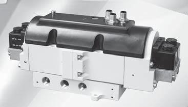
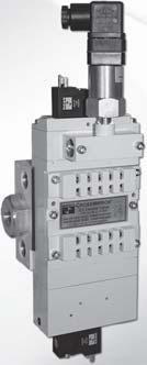
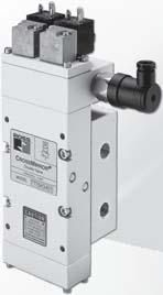
32 CONTROL RELIALE DOULE VALVES M5 SERIES KEY EATURES: Pressure sensors - allow for external monitoring of valve state Modular or threaded port connection - allows modular connection to Air Entry System (Lockout Valve, RLs) Integrated EEZ-ON (soft start) module option LED indicators - aid troubleshooting Includes high-flow, clog-resistant silencer CONTROL RELIALE DOULE VALVES RSe Series KEY EATURES Rapid response for minimum actuating time Status indicator provides valve condition (ready-to-run) feedback Position sensors for valve fault monitoring external monitoring device required Well-proven spool valve design for reliable, smooth function External pilot supply port is a standard feature ase-mounting design CONTROL RELIALE DOULE VALVES DM SERIES KEY EATURES Rapid response time to minimize stopping time Status Indicator switch for valve condition (ready-to-run) feedback Highly contaminant tolerant poppet construction Explosion proof solenoid pilot available, for more information consult ROSS These valves are not designed for controlling clutch/brake mechanisms on mechanical power presses, see DM series D valves for mechanical power press applications. Double Valves Designed for External Monitoring Double Valves Designed for External Monitoring Double Valves with Dynamic Monitoring and Memory Double Valves with Dynamic Monitoring and Memory Double Valves with Dynamic Monitoring and Automatic Reset Air Entry Packages Control Reliable Energy Isolation Lockout L-O-X Valves with Integrated ilter/regulator VALVE TYPE SERIES Category AVAILALE PORT SIZES MAX. LOW Cv MONITORING RESET /8 / /8 / / ½ Size /8 / /8 / / ½ Integrated Soft-Start External Internal Automatic Solenoid Page M RSe M DM DM C DM E DM C DM E Air Entry Packages DM Series C Preassembled Wiring Kits DM Series E Preassembled Wiring Kits DM Series C Preassembled Wiring Kits DM Series E Preassembled Wiring Kits. with M5 Series Safety Exhaust Double Valves. with DM Series C Safety Exhaust Double Valves. with DM & DM Series E Safety Exhaust Double Valves.5

33 Control Reliable Double Valves Designed for External Monitoring Safety Exhaust (Dump) M5 Series / Double Valve with or without EEZ-ON (Soft Start) Module HOW TO ORDER (Choose your options (in red) to configure your valve model number.) M5 S 0 G A E X D G A Series Soft Start unction With Soft Start S No Soft Start X Size Inlet Outlet / / 0 / / 50 Thread SPP G NPT N Voltage volts DC A Monitoring External E Communication None X * Solenoid D D A A A C AC C C CC D C DC A A AA *Pinouts details, see below. Pressure Gauge With Gauge G No Gauge X Size asic Size Revision Level Soft Start CV - - Weight lb (Kg) / 8 With (.9) / 8 Without (.9) / 8 With (.9) / 8 Without (.9) Model without EEZ-ON (Soft Start) up to Certification pending) Model with EEZ-ON (Soft Start) With optional EEZ-ON (soft start) module Solenoid Solenoid A Without EEZ-ON (soft start) module Solenoid Solenoid A Simplified Schematics With Soft Start module (Certification pending) (Certification pending) HSM xxxxxx Sicherheit geprüft tested safety (Certification pending) S + Pressure Sensors + - Output Output - SA S + Pressure Sensors + - Output Output - SA Without Soft Start module Solenoid D D A A A C AC C C CC D C DC A A AA Solenoids & Pressure Sensors Pinouts Solenoids Pressure Sensors SW A Sol A A Sol A SW SW A Sol Sol A + - C + SW SW A D Sol Sol A + C SW Design: Redundant, / Closed, Dual Poppet. Actuation: Solenoid pilot operated with air assisted spring return. One solenoid per valve element ( total) both to be operated synchronously. Mounting Type: Inline mounted - modular/threaded. Mounting Orientation: Any, preferably vertical. low Media: Compressed air according to ISO 857-:00 [7::]. Inlet Pressure: 0 to 50 psig ( to 0 bar). Ambient Temperature: 0 to 0 ( to 50 C). Media Temperature: 0 to 75 ( to 80 C). or temperatures below 0 ( C), the compressed air must be dried according to ISO 857-, class 7. Standard Voltages: volts DC. Pilot Solenoids: According to VDE Rated for continuous duty. STANDARD SPECIICATIONS (for valves on this page): Pilot Solenoids Power Consumption (each solenoid):. watts. Enclosure Rating: According to DIN IP 65. Electrical Connections: Two 5-pin M connectors. Enclosure rating according to DIN IP 65. Pressure Sensors ( per valve): Solid state. Pressure Sensors Current Consumption (each sensor): <ma (each without contacts). Monitoring: Dynamic, cyclical, external with customer supplied equipment. Monitoring should check state of both valve pressure sensors with any and all changes in state of valve control signals. Minimum Operation requency: Once per month, to ensure proper function. unctional Safety Data: Pending. This valve is not designed for controlling clutch/brake mechanisms on mechanical power presses, see DM Series D valves for mechanical power press applications. Rev. 0/0/7.
34 Control Reliable Double Valves Designed for External Monitoring M5 Series Valve Overview & Options With optional EEZ-ON (soft start) module.7 (9.7) 0.6 (6.) Exhaust Status Indicator ( LED'S) Without EEZ-ON (soft start) module 0.6 (6.) Valve Dimensions inches (mm) Status Indicator ( LED'S).0 (09.) Outlet Inlet 7.0 (78.7) Outlet 0. (6.9). (79.0). (79.0) 6.9 (6.) Inlet 6.9 (6.). (6.5). (0.) Exhaust.5 (80.0).7 (9.7).87 (7.0).0 (09.). (6.5). (0.).5 (80.0) Soft Start Adjustment.87 (7.0).0 (09.).0 (09.) VALVE OPERATION Conditions at Start: Inlet is closed to outlet by both valve elements A and. Outlet is open to exhaust. Pressure signals at both sensors SA and S are exhausted. Sensors outputs SA and S are on. + Pb - C D Output S A + SA Pa - Output Mounting rackets & Clamp for Module Connections Description racket and Screw Clamp racket, screw, and Clamp Normal Operation: Simultaneously energizing both solenoids actuates both pilots and causes valve elements A and to shift. Inlet is then connected to outlet via crossflow passages C and D. Exhaust is closed. Sensing pressure signals go to each pressure sensor and become equal to inlet pressure. Sensors outputs SA and S are off. Model Number R-A8-0 R-A8-05 R-A8-05M Pb A Pa Output Output S SA Size / / Completion of Normal Cycle: Simultaneously de-energizing both solenoids returns the valve to the Conditions at Start described at left. Detecting a Malfunction: A malfunction in the system or the valve itself could cause one valve element to be open and the other closed. Air then flows past the inlet poppet on valve element A, into crossflow passage D, but is substantially blocked by the spool portion of element. The large size of the open exhaust passage past element keeps the pressure at the outlet port below % of inlet pressure. ull sensing air pressure from side A goes to sensor SA, and a reduced pressure goes to sensor S. This full pressure signal causes sensor outputs SA to turn off. Sensor outputs S, with a reduced pressure signal, does not turn on. An external monitoring system can detect the malfunction by monitoring the condition of the sensors SA and S. The external monitoring system may then react accordingly by shutting down the power to the valve solenoids and any other components deemed necessary to stop the machine. Type End s NPT Threads Model Number SPP Threads emale R R-8-00-W Male R R-8-09-W emale R R W Male R R W + S Pb C D A + Pa - - ACCESSORIES & OPTIONS M5 Series valves have both modular receptacles for piping and female threaded ports inside receptacles, which allows either modular connection or direct piping. Mounting accessories listed below are used for modular connection to ROSS MD Series filter-regulator units. Pressure Gauge Size Model Number* Pressure Range psig (bar) Case Diameter inches (mm) /8 500A (0-).5 (8) * Center back mounting; male pipe threads. Size Output Extra locks NPT Threads Model Number SA Output SPP Threads / R R-8-06-W emale End Male End lock Wiring Kits Connector Type M System Cables Connector - one end Description Cords with female, 5-pin, straight, A-coded connector on one end and flying leads on the opposite end. Cords with female, 5-pin, straight, A-coded M System Cables connector on one end and male, 5-pin, straight, Connector - both ends A-coded connector on the opposite end. Kit Number Number of Cables Cord Length meters (feet) (6.) (6.) 5 Wire Colors rown White lue lack 5 Grey. 07, ROSS CONTROLS. All Rights Reserved. Rev. 0/0/7
35 Control Reliable Double Valves Designed for External Monitoring Safety Exhaust (Dump) RSe Series / Redundant Double Valve Sub-base Mounted HOW TO ORDER (Choose your options (in red) to configure your valve model number.) RSe E D A 0 A P Coming Series External Revision Automatic Sensor Monitoring Level Reset Type eedback Type/unction / Thread Voltage Sensor SPP D Soon! Inlet Outlet volts DC A Sensor Output PNP NPT N /8 /8 0 / / 0 / / 0 P Size C V - - Weight lb (Kg) / (.) / (.7) / (.99) (Certification pending) (Certification pending) HSM xxxxxx Sicherheit geprüft tested safety (Certification pending) The / RSe Series valve is designed to supply air to a zone or entire machine/system until signaled to shut off and exhaust residual downstream pneumatic energy from the machine. Thus, reducing the hazards associated with the presence of residual energy during employee access and/or minor servicing. The safety function of the / RSe Series valve is to shut off supply of pneumatic energy and to exhaust any pneumatic energy from downstream of the valve. Note: The / RSe Series valve cannot exhaust pneumatic energy from downstream of obstructions such as check valves and closed center function valves. The RSe Series valves are designed for external monitoring for safe, redundant operation of the valves. The RSe Series valves are constructed of redundant, / spool type valves, and have an overall function of a single solenoid pilot-operated, spring return valve. Each single valve in the RSe Series is equipped with a NPN or PNP proximity sensor. Monitoring both of these sensors on each actuation and de-actuation of the RSe Series valve provides a diagnostic coverage of 99%. Monitoring of these sensors is to be done by an external monitoring system. Simplified Schematics STANDARD SPECIICATIONS (for valves on this page): Construction: Spool and sleeve. Mounting Type: ase. Actuation: Solenoid pilot operated with spring return. One solenoid per valve element both to be operated synchronously. Solenoid: Version as per VDE Rated for continuous duty. Electrical connection according to EN orm C. Enclosure rating according to DIN IP 65. Standard Voltages: volts DC. Power Consumption (each solenoid):. watts on DC. Proximity Sensors ( per valve): PNP. Current Consumption (each sensor): <ma. Ambient/Media Temperature: 0 to 0 ( to 50 C). low Media: Compressed, filtered air according to ISO 857- Class 7::. Inlet Pressure: With internal pilot supply: to 5 psig ( to 0 bar). With external pilot supply: 0 to 5 psig (0 to 0 bar). Pilot Pressure: Must be equal to or greater than inlet pressure. Mounting Orientation: Any, preferably vertical. Monitoring: Dynamic, cyclical, external with customer supplied equipment. Monitoring should check state of both valve pressure sensors with any and all changes in state of valve control signals. unctional Safety Data: Pending. This valve is not designed for controlling clutch/brake mechanisms on mechanical power presses, see DM Series D valves for mechanical power press applications. Rev. 0/0/7.5
36 Control Reliable Double Valves Designed for External Monitoring M5 Series Valve Overview & Options Size /8.96 (75.0) 0. (6.00).97 (00.8). (9.0).67 (.5) Outlet.9 (7.8).67 (67.8).8 (0.0) 0.7 (9.5) Inlet (0.9) (7.9) Valve Dimensions inches (mm).67 (9.) 0,79 (0.) 0.77 (9.5) 0.5 (.5) External Pilot Exhaust Supply /8 NPT 0. (6.0).8 (7.5) Size /. (.0).8 (0.0). (8.0) 0. (5.5).97 (50.0).6 (.0) Outlet.79 (5.5).99 (76.0) 0. (.0) Inlet.8 (0.0).8 (0.0) 0.98 (5.0) Exhaust.99 (0.) 0.5 (.0) 0.6 (6.55) External Pilot Supply /8 NPT.89 (98.9) 0.8 (7.0) Ø0.6 (6.5) 0.0 (7.5).6 (.0) Size / 6.8 (7.0).8 (0.0) Inlet External Pilot Supply /8 NPT 0. (6.0).66 (9.0).56 (90.5) 0.8 (.0).56 (5.9) 0.8 (7.0).8 (6.5) 0. (0.).78 (96.0).65 (.0) Outlet.6 (66.5) 0.67 (7.0).9 (8.5).67 (.5) 0.66 (7.0) Exhaust 0. (.00) ACCESSORIES & OPTIONS Silencers Size Thread Type Model Number Avg. C V Dimensions inches (mm) NPT Threads SPT Threads A Weight lb (kg) /8 Male 5500A00 D5500A ().0 (5) 0. (0.) / Male 5500A00 D5500A (). (55) 0. (0.) / Male 5500A00 D5500A00.7. ().6 (9) 0. (0.) Pressure Range: 0 to 00 psig (0 to 0.7 bar) maximum. Electrical Connectors low Media: iltered air. A Connection Solenoid Electrical Connector orm DIN EN orm C Electrical Connector Type Cord Length meters (feet) Cord Diameter Without Light Model Number Lighted Connector Volts DC Prewired Connector (8 gauge) (0) 8-mm 9K77 50K77-W DIN 650 orm C Connector Only 5K77 5K77-W eedback Sensor M8 Connector (sensing) Prewired Connector (6.5) CAUTIONS: Do not use electrical connectors with surge suppressors, as this may increase valve response time when de-actuating the solenoids. Preassembled Wiring Kits Valve Size Lighted Connector / & 5/ Connector Type EN orm C (solenoids) M8 (sensors) Length meters (feet) (6.5) * Each cable has one connector. Kits include cables for the sensors (M8), and cables (EN orm C) with connector plus a cord grip for each. Solenoid Cables with EN connector RN PIN RN NOT USED LUE PIN GRN/YEL GROUND LUE GRN/YEL Sensor Wiring M8 Connector L+ L- Wire Colors rown lue lack.6 07, ROSS CONTROLS. All Rights Reserved. Rev. 0/0/7
37 Control Reliable Double Valves with Dynamic Monitoring and Memory Safety Exhaust (Dump) M DM Series C / Double Valves with Integrated EEZ-ON (Soft Start) Dynamic Monitoring With Memory: Memory, monitoring, and air flow control functions are integrated into two identical valve elements. Valves lock-out if asynchronous movement of valve elements occurs during actuation or de-actuation, resulting in a residual outlet pressure of less than % of supply. An Action is Required for Reset: Cannot be reset by removing and re-applying supply pressure. Reset can be accomplished by the integrated electrical (solenoid) reset or by the manual reset button. asic / Closed Valve unction: Dirt tolerant, wear compensating poppet design for quick response and high flow capacity. PTE back-up rings on pistons to enhance valve endurance operates with or without inline lubrication. LED Indication: Light-emitting diode (LED) indicators of main solenoid operation, reset solenoid operation, and status indicator condition. Status Indicator: Includes a pressure switch with both normally open (NO) and normally closed (NC) contacts to provide status feedback to the control system indicating whether the valve is in the lockout or ready-to-run condition. Transducer (optional): or monitoring of downstream pressure in the system. Silencers: All models include high flow, clog resistant silencers. HOW TO ORDER (Choose your options (in red) to configure your valve model number.) MDMC N A 5 5 A HSM 50 Sicherheit seprüft tested safety ISO 89-:006 Category PL e applications U.S. Patent No , (Worldwide Patents Pending) SPP D N Level Size Size Inlet Outlet 8 / / 5 Solenoid * A No Simplified Schematic Valve Dimensions inches (mm) Inlet Outlet asic Size 8 Size Transducer CV - - Weight lb (Kg) / WIth (7.) / Without (7.) 0.78 (7.8) 5.7 (5.5).6 (.) 5.5 (6.0) 5.8 (7.6) Adjustable low Control Valve Wiring ROWN (+ Volts DC) 5 Pin A Code emale Connector 5 Pin A Code Male Connector LACK (N.C. Status Contact) WHITE (Sol ) LUE (Common) 5 5 WHITE (N.O. Status Contact) GRAY (Equip. Ground) LUE (Common) ROWN (+ Volts DC) GRAY (Reset) LACK (Sol ) Mounting brackets are required to install valve in the system, see M DM Series C accessories for ordering information page.8. Construction: Dual Poppet. Mounting Type: ase mounted. Pilot Solenoids: According to VDE Enclosure rating according to DIN IP 65. Three solenoids, rated for continuous duty. Standard Voltages: volts DC. Pilot Solenoids Power Consumption (each solenoid): Primary and reset solenoids:. watts on DC. Enclosure Rating: IP65, IEC Solenoid & Status Indicator Connection: M, 5-pin Male Receptacle, A-Coded. Ambient Temperature: 5 to (-0 to 50 C). Media Temperature: 0 to 75 ( to 80 C). low Media: iltered, lubricated or unlubricated (mineral oils according to DIN 559, viscosity classes -6); 5-micron recommended. STANDARD SPECIICATIONS (for valves on this page): Inlet Pressure: 0 to 50 psig ( to 0 bar). Under certain circumstances, such as maximum restriction of the adjustable flow control or a very large downstream system volume, the minimum inlet pressure may need to be set up to 60 psig ( bar) to prevent nuisance valve faults. Pressure Switch (Status Indicator) Rating: 5 amps at 0 volts DC. Monitoring: Dynamically, cyclically, internally during each actuating and de-actuating movement. Monitoring function has memory and requires an overt act to reset unit after lockout. Mounting Orientation: Vertically with pilot solenoids on top. unctional Safety Data: Category PL e; 0D: 0,000,000; PHD: 7.7x0-9 ; MTTD: 0.9 (n op : 6600). Certifications: CE Marked for applicable directives, CSA/UL. Vibration/Impact Resistance: Tested to S EN This valve is not designed for controlling clutch/brake mechanisms on mechanical power presses, see DM series D for mechanical power press applications. Rev. 0/0/7.7
38 EXHAUST OUTLET INLET EXHAUST OUTLET INLET EXHAUST OUTLET INLET Control Reliable Double Valves with Dynamic Monitoring and Memory M DM Series C Valve Operation Valve de-actuated (ready-to-run): The flow of inlet air pressure to the inlet chamber of the main valve internals is restricted by a fixed orifice and an adjustable flow control as well as an air piloted -way normally closed poppet valve. The flow of inlet air pressure into the crossover passages is restricted by the size of the passage between the stem and the valve body opening. low is sufficient to quickly pressurize pilot supply/timing chambers A and. The inlet poppets prevent air flow from crossover passages into the outlet chamber. Air pressure acting on the inlet poppets and return pistons securely hold the valve elements in the closed position. (Reset adapter omitted for clarity.) ADJUSTING NEEDLE EXHAUST OUTLET A INLET ADJUSTING NEEDLE EXHAUST OUTLET INLET A Valve actuated: Energizing the pilot valves simultaneously applies pressure to both pistons, forcing the internal parts to move to their actuated (open) position, where inlet air flow to crossover passages is fully open, inlet poppets are fully open and exhaust poppets are fully closed. The outlet is then pressurized at a rate allowed by the fixed orifice and the adjusted flow control. Once the air pressure in the outlet chamber reaches approximately 60% of inlet pressure, the air piloted -way normally closed poppet valve opens fully and the pressure in the inlet, crossovers, outlet, and timing chambers are quickly equalized. The adjustable flow control will control the time it takes for the outlet air pressure to reach approximately 60% of inlet pressure. Green SOL. and SOL. LEDs will be displayed when the main solenoids are energized. De-energizing the pilots quickly causes the valve elements to return to the ready-to-run position. Valve locked-out: Whenever the valve elements operate in a sufficiently asynchronous manner, either on actuation or de-actuation, the valve will move to a locked-out position. In the locked-out position, one crossover and its related timing chamber will be exhausted, and the other crossover and its related timing chamber will be fully pressurized. The valve element (side ) that is partially actuated has pilot air available to fully actuate it, but no air pressure on the return piston to fully de-actuate the valve element. Air pressure in the crossover acts on the differential of side stem diameters creating a latching force. Side A is in a fully closed position, and has no pilot air available to actuate, but has full pressure on the inlet poppet and return piston to hold the element in the fully closed position. Inlet air flow on side A into its crossover is restricted, and flows through the open inlet poppet on side, through the outlet into the exhaust port, and from the exhaust port to atmosphere. Residual pressure in the outlet is less than % of inlet pressure. The return springs are limited in travel, and can only return the valve elements to the intermediate (locked-out) position. Sufficient air pressure acting on the return pistons is needed to return the valve elements to a fully closed position. ADJUSTING NEEDLE EXHAUST OUTLET INLET A Resetting the valve: The valve will remain in the locked-out position, even if the inlet air supply is removed and re-applied. A remote reset signal must be applied to reset the valve. A momentary, remote electrical signal must be applied to the reset solenoid to apply pressure to the reset pistons in the valve. Actuation of the reset piston physically pushes the main valve elements to their closed position. Inlet air fully pressurizes the crossovers and holds the inlet poppets on seat. Actuation of the reset piston opens the reset poppet, thereby, immediately exhausting pilot supply air, thus, preventing valve operation during reset (Reset adapter added to illustration.). De-actuation of reset pistons causes the reset poppets to close and pilot supply to fully pressurize. Reset air pressure is applied by a / normally closed solenoid, or a manual push button mounted on the reset adapter in the top valve cover. A green RESET SOL. LED will be displayed when the reset solenoid is energized. The reset procedure is as follows: Remove the electrical signals to the main coils Ensure there is air supplied to the valve Energize the reset solenoid for a minimum of 00 ms ADJUSTING NEEDLE EXHAUST Allow a 00 ms delay after de-energizing the reset solenoid and re-energizing the main solenoids OUTLET INLET A Exh. Pressure Switch Status Indicator: The status indicator pressure switch will actuate when the main valve is operating normally, and will de-actuate when the main valve is in the locked-out position or inlet pressure is removed. This device is not part of the valve lockout function, but, rather, only reports the status of the main valve. If the valve is in a ready-to-run condition, a green STATUS LED will be displayed. If the valve is faulted or there is no air pressure at the inlet, a red STATUS LED will be displayed. Status indicator in normal ready-to-run position Exh. Exh. Schematic - Valve de-actuated Reset port.8 Rev. 0/0/7
 M DM Series C Precision digital pressure transducer with 5 pin female connection Two PNP digital outputs which may be set individually, -0 ma analog output Three operation modes: Easy,")
. Includes two cords, and the cord grips. Wiring Kit with Transducer - 5 meters (6. feet). Includes three cords, and the cord grips.")

39 Accessories & Options Digital Pressure Transducer Model Number 7H77 ROWN Input Power + LACK Analog Output Signal 5 WHITE Digital Output Signal GREY Power Input LUE Digital Output Signal for Safety Exhaust (Dump) M DM Series C Precision digital pressure transducer with 5 pin female connection Two PNP digital outputs which may be set individually, -0 ma analog output Three operation modes: Easy, Window and Hysteresis Selectable response times to eliminate output chattering Powered by - vots DC 6 pressure unit conversions Lockable keypad ast zero reset Wiring Kits Kit Number H77 H77 Mounting Accessories Length Wiring Kit - 5 meters (6. feet). Includes two cords, and the cord grips. Wiring Kit with Transducer - 5 meters (6. feet). Includes three cords, and the cord grips. At least two mounting brackets should be used. This can consist of two clamp mounting brackets or one clamp mounting bracket and one mounting bracket Kit Number H77. Mounting rackets & Clamp for Module Connections Male and emale End s Two brackets are normally used to mount an RL to a vertical surface. The mounting bracket attaches to the module connecting clamp (see above) with a single screw. Each bracket then employs two bolts (/ or 6mm) to connect the assembly to the mounting surface. Specially designed clamps provide a quick and easy assembly or disassembly of MD TM modules. Two allen-head bolts quickly tighten or loosen the clamp using a 5/ or mm hex key. The clamp contains a plate carrying two O-rings to provide positive sealing between modules. Mounting rackets & Clamp for Module Connections Description racket and Screw Module Connecting Clamp racket, Screw, and Clamp Model Number R-A8-0 R-A8-05 R-A8-05M racket, Screw, and Clamp Module Connecting Clamp Mounting racket Either male or female end ports can be attached to threaded inlet and outlet lines. This allows all modules of an RL assembly to be removed easily and quickly without having to unthread the end modules. The end ports are attached to the modules with clamps (see at left). End ports can be included in an assembled RL or ordered separately by the following model numbers: Size / /8 / / Type End s NPT Threads Model Number SPP Threads emale R R-8-00-W Male R R-8-09-W emale R R-8-00-W Male R R-8-09-W emale R R-8-00-W Male R R-8-09-W emale R R W Male R R W emale End Male End Extra locks An extra port block can be placed between modules to provide two auxiliary / NPT ports. Its mounting position can be rotated to obtain the most convenient operating orientation. If only one auxiliary port is to be used, the unused port must be closed with a pipe plug. (The inlet and outlet are not threaded.) Size NPT Threads Model Number SPP Threads / R R-8-06-W /8 R R-8-06-W / R R-8-06-W Mounting racket Kit Mounting racket Kit includes bracket and bolts to mount to the valve end plate. Kit Number H (9.) 0.75 (9.5) 0. (8.). (8.) 0.5 (6.).8 (6.) 0. (.).0 (76.).875 (98.) 8X R 0..0 (76.) R (76.) Rev. 0/0/7.9
40 Control Reliable Double Valves with Dynamic Monitoring and Memory Safety Exhaust (Dump) DM Series C asic Size,, 8, and 0 Dynamic Monitoring With Complete Memory: Memory, monitoring, and air flow control functions are simply integrated into two identical valve elements. Valves lock-out due to asynchronous movement of valve elements during actuation or de-actuation, resulting in a residual outlet pressure of less than % of supply. An Action is Required for Reset cannot be reset by removing and re-applying supply pressure. Reset can only be accomplished by the integrated electrical (solenoid) reset. asic / Closed Valve unction: Dirt tolerant, wear compensating poppet design for quick response and high flow capacity. PTE back-up rings on pistons to enhance valve endurance operates with or without inline lubrication. Status Indicator: Includes a pressure switch with both normally open (NO) and normally closed (NC) contacts to provide status feedback to the control system indicating whether the valve is in the lockout or ready-to-run condition. Silencers: All models include high flow, clog resistant silencers. Mounting: ase mounted with SPP or NPT pipe threads. Inlet and outlet ports on both sides provide for flexible piping (plugs for unused ports included). Captive valve-to-base mounting screws. asic Size and 0 Intermediate Pilots: Increases pilot air flow for fast valve response, making it possible to use the same size solenoids as valve sizes, & 8, thereby reducing electrical power requirements for these larger valves. HSM Sicherheit seprüft tested safety ISO 89-:006 Category PL e applications HOW TO ORDER (Choose your options (in red) to configure your valve model number.) DMC N A A Thread SPP D NPT N Revision Level Size, 8,, 0 A Size asic Size Size Size Inlet Outlet / /8 / /8 0 / / 8 / / ½ 8 Solenoid Reset Type Status Indicator Yes No X Voltage* volts DC A 0 volts AC, 50 Hz 0 volts AC, 50/60 Hz * or other voltages consult ROSS. Explosion proof valves available, see explosion proof valves. * (connector not included) M (connector included) 005 Silicone ree with EN orm A 00 (connector not included) Silicone ree with M 05 (connector included) *See options for connectors or wiring kits. Simplified Schematic asic Size Inlet Size CV - - Weight lb (Kg) / (.) / (.) / (.6) 8 /. 8. (.7). 8. (.7) (.7) 0 ½ 6.7 (5.) # Valve and base assembly with status indicator. Construction: Dual poppet. Mounting Type: ase mounted. Pilot Solenoids: According to VDE Enclosure rating according to DIN IP 65. Three solenoids, rated for continuous duty. Standard Voltages/Pilot Solenoids Power Consumption (each solenoid): asic Size,, & 0: Primary and reset solenoids: volts DC; 0 volts AC, 50 Hz; 0 volts AC, 50/60 Hz. 5.8 watts nominal on AC and DC; 6.5 watts maximum on AC and DC. asic Size 8: Primary solenoids: 5 watts on DC; 6 VA inrush and.6 VA holding on AC. Reset solenoid: 6.0 watts on DC; 5.8 VA inrush and 0. VA holding on AC. Enclosure Rating: IP65, IEC Electrical Connection: EN orm A, or M. Ambient Temperature: 5 to (-0 to 50 C). Media Temperature: 0 to 75 ( to 80 C). STANDARD SPECIICATIONS (for valves on this page): low Media: iltered, lubricated or unlubricated (mineral oils according to DIN 559, viscosity classes -6). Inlet Pressure: asic Size : 5 to 50 psig (. to 0. bar). asic Size, 8,, 0: 0 to 0 psig (. to 8. bar). Pressure Switch (Status Indicator) Rating: Contacts - 5 amps at 50 volts AC, or 5 amps at 0 volts DC. Monitoring: Dynamically, cyclically, internally during each actuating and de-actuating movement. Monitoring function has memory and requires an overt act to reset unit after lockout. Mounting Orientation: Preferably horizontally (valve on top of base) or vertically with pilot solenoids on top. unctional Safety Data: Category PL e; 0D: 0,000,000; PHD: 7.7x0-9 ; MTTD: 0.9 (n op : 6600). Certifications: CE Marked for applicable directives, DGUV Test, CSA/UL, TSSA for appropriately tested valves. Vibration/Impact Resistance: Tested to S EN This valve is not designed for controlling clutch/brake mechanisms on mechanical power presses, see DM series D for mechanical power press applications..0 07, ROSS CONTROLS. All Rights Reserved. Rev. 0/0/7
41 Control Reliable Double Valves with Dynamic Monitoring and Memory DM Series C Valve Technical Data Valve Dimensions inches (mm) asic Size asic Size 0.89 (76.7).50 (.). (0.) Main Solenoids Status Indicator / NPT View X Outlet (Each Side) 9.97 (5.).00 (0.8) Main Solenoids 7.90 (00.8).99 (75.9) 0. (6.) / NPT Inlet (Each Side) Status Indicator.7 (0.) 0.57 (.5) 6. (60.8) Outlet (Each Side) Inlet (Each Side).9 (0.) 0.8 (0.9) Solenoid Reset 0.97 (.6). (.5) Solenoid Reset View X (ase mounting hole pattern) Valve envelope (ased in overall hole dimnsions at left.) 0. (5.6) ( places).00 (0.6).99 (75.9).00 (0.6) (ase mounting hole pattern) Valve envelope (ased in overall hole dimensions at left.) 0.7 (6.9) ( places).68 (9.5). (.5). (0.) 0.6 (.06).00 (0.6).0 (5.9).7 (69.6) 0.5 (6.) 0.65 (6.6) Status Indicator Pressure Switch Pilot booster on Size & 0 only Solenoid Reset Reset asic Size 8.7 (.) 5. (7.) Main Solenoids / or NPT Inlet (Each Side) / or NPT Outlet (Each Side) Status Indicator. (6.).9 (8.8) View X (ase mounting hole pattern) Valve envelope (ased in overall hole dimensions at left.).60(6.8) 6. (58.) 0.6 (.) Schematic - Valve de-actuated.90 (8.).8 (08.7) 0.86 (.9) asic Size.7 (8.) 6.7 (7.). (6.) Main Solenoids 7.8 (90) 9. (9.) Solenoid Reset.67 (.) 0. (8.6) ( places) Status Indicator NPT Outlet (Each Side).6 (59.9).07 (5.6) NPT Inlet (Each Side) Solenoid Reset.68 (68.) View X (ase mounting hole pattern) Valve envelope (ased in overall hole dimensions at left.) 5.86 (8.8) 7.7 (89.7) 0. (0.7) ( places) 0.57 (.5).7 (9.9).6 (0.9).59 (0.) asic Size (50.) Main Solenoids.8 (00.) Status Indicator NPT Outlet (Each Side).95 (9.5) View X (ase mounting hole pattern) Valve envelope (ased in overall hole dimensions at left.) 8.6 (.9) 0.50 (.7) ( places) 6.87 (8.5). (8.8).6 (9.5) 9.7 (7.).5 (6.5) -/ NPT Inlet (Each Side) Solenoid Reset 6. (56). (6.5).7 () Rev. 0/0/7.
42 EXHAUST OUTLET INLET EXHAUST OUTLET INLET EXHAUST OUTLET INLET Control Reliable Double Valves with Dynamic Monitoring and Memory DM Series C Valve Operation & Options Valve de-actuated (ready-to-run): The flow of inlet air pressure into the crossover passages is restricted by the size of the passage between the stem and the valve body opening. low is sufficient to quickly pressurize pilot supply/timing chambers A and. The inlet poppets prevent air flow from crossover passages into the outlet chamber. Air pressure acting on the inlet poppets and return pistons securely hold the valve elements in the closed position.(air passages shown out of position and reset adapter omitted for clarity.) EXHAUST OUTLET INLET A Valve actuated: Energizing the pilot valves simultaneously applies pressure to both pistons, forcing the internal parts to move to their actuated (open) position, where inlet air flow to crossover passages is fully open, inlet poppets are fully open and exhaust poppets are fully closed. The outlet is then quickly pressurized, and pressure in the inlet, crossovers, outlet, and timing chambers are quickly equalized. De-energizing the pilots quickly causes the valve elements to return to the ready-to-run position. EXHAUST OUTLET INLET A Valve locked-out: Whenever the valve elements operate in a sufficiently asynchronous manner, either on actuation or de-actuation, the valve will move to a locked-out position. In the locked-out position, one crossover and its related timing chamber will be exhausted, and the other crossover and its related timing chamber will be fully pressurized. The valve element (side ) that is partially actuated has pilot air available to fully actuate it, but no air pressure on the return piston to fully de-actuate the valve element. Air pressure in the crossover acts on the differential of side stem diameters creating a latching force. Side A is in a fully closed position, and has no pilot air available to actuate, but has full pressure on the inlet poppet and return piston to hold the element in the fully closed position. Inlet air flow on side A into its crossover is restricted, and flows through the open inlet poppet on side, through the outlet into the exhaust port, and from the exhaust port to atmosphere. Residual pressure in the outlet is less than % of inlet pressure. The return springs are limited in travel, and can only return the valve elements to the intermediate (locked-out) position. Sufficient air pressure acting on the return pistons is needed to return the valve elements to a fully closed position. EXHAUST OUTLET INLET A Resetting the valve: The valve will remain in the locked-out position, even if the inlet air supply is removed and re-applied. A A remote reset signal must be applied to reset the valve. Reset is accomplished by momentarily pressurizing the reset port. EXHAUST Actuation of the reset piston physically pushes the main valve OUTLET elements to their closed position. Inlet air fully pressurizes the crossovers and holds the inlet poppets on seat. Actuation of INLET the reset piston opens the reset poppet, thereby, immediately exhausting pilot supply air, thus, preventing valve operation during reset (Reset adapter added to illustration.). De-actuation of reset pistons causes the reset poppets to close and pilot supply to fully pressurize. Reset pressure can be applied by a remote / normally closed valve, or from an optional / normally closed solenoid mounted on the reset adapter. De-actuation of reset pistons causes the reset poppets to close and pilot supply to fully pressurize. Reset air pressure can be applied by a remote / normally closed valve, or from an optional / normally closed solenoid, or a manual push button mounted on the reset adapter. ACCESSORIES & OPTIONS Electrical Connectors Electrical Connector orm Downstream Pressure Monitoring Pressure Switches Connection Type Model Number Threads EN orm A 586A86 /8 NPT M 5A0 /8 NPT *Pressure switch closes on falling pressure of 5 psig (0. bar). Electrical Connector Type High-low, High Reduction Silencer Kits Status Indicator:The status indicator pressure switch will actuate when the main valve is operating normally, and will de-actuate when the main valve is in the locked-out position or inlet pressure is removed. This device is not part of the valve lockout function, but, rather, only reports the status of the main valve. A Cord Length meters (feet) Redundant Downstream eedback Switch asic Size and 0 valves require relatively large pilots to actuate and de-actuate the main valve elements. In order to achieve extremely quick valve response for such large pilots, a -stage solenoid pilot system is incorporated into the design. This keeps the required electrical current to operate the pilots to a minimum. asic Size & 0 pilots Cord Diameter Model Number RC06- May be installed downstream on all double valves Provides a redundant means to verify the release of downstream pressure to next obstruction actory preset, 5 psi (0. bar) - falling A Status indicator in normal ready-to-run position. Electrical Connector Model Number Without Lighted Connector Light Volts DC 0 Volts AC Prewired Connector (8 gauge) (6½) 6-mm 7K77 70K77-W 70K77-Z Prewired Connector (8 gauge) (6½) 0-mm 7K77 8K77-W 8K77-Z EN orm A Connector for threaded conduit 7K77 7K77-W 7K77-Z (/ inch electrical conduit fittings) Connector Only 97K87 96K87-W 96K87-Z CAUTIONS: Do not use electrical connectors with surge suppressors, as this may increase valve response time when de-actuating the solenoids. EN Connector Pinout Open Common Closed Ground M Connector Pinout Pin Open Pin Common Pin Not Used Pin Closed Threads /8 NPT Kit Number* low Dimensions inches (mm) Size NPT threads SPT threads scfm A (NPT) (SPT) C H77 9H (78). (0.) 9.06 (8.).0 (5.6) 7.7 (8.7) 8 5H77 9H (78) 5. (7.).8 (58.0).5 (597.) 8. (.6) 6H77 0H (98) 6.7 (7.) 5.85 (656.6) 8.0 (76.) 0.66 (70.8) 0 7H77 H (98) 9.85 (50.).55 (055.).55 (055.).7 (.) * Kits include all plumbing required for installation. Pressure Range: 5 psig (8.6 bar) maximum. Designed to improve equipment performance and reduce the Exponentially Perceived Noise (EPNd) in the 5 0 d range.. C Rev. 0/0/7
 Volts DC 0 Volts AC 8H77 5H77-W 5H77-Z EN 750-80 orm A 5 (6.) 8H77 5H77-W 5H77-Z EN 750-80 orm A 0 (.")
43 Preassembled Wiring Kits for Safety Exhaust (Dump) DM Series C Preassembled Wiring Kits These kits include cable for the status indicator, and cables with connector plus a cord grip for each. Kit Number* Length Solenoid Connector Connector Lighted Connector meters Type without Light (feet) Volts DC 0 Volts AC 8H77 5H77-W 5H77-Z EN orm A 5 (6.) 8H77 5H77-W 5H77-Z EN orm A 0 (.8) 88H77 M 5 (6.) 89H77 M 0 (.8) * Each cable has one connector. Solenoid Cables with EN connector NOT USED RN PIN RN LUE GRN/YEL LUE PIN GRN/YEL GROUND Solenoid Cables with M Connector LUE LACK LACK LUE Status Indicator Cable with EN connector GRY RN LK GRY LK RN GRN/YEL GROUND Wiring Kits with J-ox Kit Number* A J-ox is a junction box with a 0-pin MINI connector for connecting to the user s control system and () 5-pin M ports for connecting to the solenoids and the status indicator on the DM Series valve. The J-ox kits include the J-ox as described above and () -meter cables for connecting to the valve. These cables have a connector on each end. The status indicator cable and the () solenoid cables have an M connector on one end and a EN connector on the other end (M-DIN). Standard valves come with DIN type solenoid connections, but could be bought with M type connections as well. Therefore we also offer a kit that provides solenoid cables with an M connector on each end (M-M). Connector Types Length meters (feet) 9H77 M - DIN (.) 50H77 M - M (.) * volts DC only..85 (6.9) (5.9).5-6UNA.90 (7.6).9 (00).0 (5) dia. 0.8 [.5] 0 Pin Pin # (V+) (V-) Pin # Pin # Pin # Pin # J-ox Wiring 0 PIN MINI Cable These cables have a 0-pin MINI connector for connecting the J-ox kits above to the user s control system. Kits include one cable with connector and cord grip. Cable conductors are 8-gauge wire. Kit Number Length meters (feet) 5H77.66 () 5H77 6. (0) 55H77 9. (0) 56H77 5. (50) PIN # + volts DC Common volts DC - Solenoid A 5 Solenoid PIN # 6-7 Remote Reset 8-9 Remote Valve ault Light 0 Remote System OK Light Wire Colors: Orange lue White w/lack Red w/lack Green w/lack Wire Colors: Orange w/lack Red Green/Yellow lack White Outlet Pressure Monitoring Wiring Kit Kit Number Length meters (feet) 5H77 (.) Some customers prefer to monitor downstream pressure in addition to using the DM or DM Series valve. A convenient way to do this is to install a pressure switch in the extra outlet port that is provided on the valve. The Outlet Pressure Monitoring kit can be Mx emale used with one of the J-ox kits above to split one of the M ports on the J-ox so that a pressure switch can be wired in as well. These kits consist of one port splitter (a Tee with three M connectors) and one M-DIN cable ( meter). Pressure switch available separately, see valve options. Ø0.6 (0) 0. (7) 0.7 (0).6 Mx Male (0).6 EMALE A 5 5 MALE PORT SPLITTER 5 EMALE 5 Rev. 0/0/7.

44 Control Reliable Double Valves with Dynamic Monitoring and Memory Safety Exhaust (Dump) DM Series E Dynamic Monitoring with Memory: Memory, monitoring, and air flow control functions are integrated into two identical valve elements for CAT applications, except control of the clutch/brake mechanism on mechanical power press. Valves lock-out if asynchronous movement of valve elements occurs during actuation or de-actuation, resulting in a residual outlet pressure of less than % of supply. An Action is Required for Reset cannot be reset by removing and re-applying supply pressure or electrical power. Reset can only be accomplished by the integrated electrical (solenoid) reset. asic / Closed Valve unction: Dirt tolerant, wear compensating poppet design for quick response and high flow capacity. PTE back-up rings on pistons to enhance valve endurance operates with or without inline lubrication. Status Indicator: Includes a pressure switch with both normally open (NO) and normally closed (NC) contacts to provide status feedback to the control system indicating whether the valve is in the lockout or ready-to-run condition. Silencers: All models include high flow, clog resistant silencers. Mounting: Inline mounted with SPP or NPT pipe threads. Inlet and outlet ports on both sides provide for flexible piping (plugs for unused ports included). HOW TO ORDER (Choose your options (in red) to configure your valve model number.) DME N A 0 A HSM 0 Sicherheit seprüft tested safety ISO 89-:006 Category PL e applications Thread SPP D NPT N Revision Level asic Size Size Size Inlet Outlet / / 0 /8 /8 Exhaust port size /" Solenoid Reset Type Status Indicator Yes No X Voltage* volts DC A 0 volts AC, 50 Hz 0 volts AC, 50/60 Hz * or other voltages consult ROSS. Connection Type EN orm A* (connector not included) Leave lank M (connector included) 005 *See options for connectors or wiring kits. Status Indicator Pressure Switch Pilot booster on Size & 0 only Valve Dimensions inches (mm) 0.57 (.5).56 (0.0).87 (.6).66 (67.6).96 (6.) Valve Mounting.86 Pattern (7.6).0 (06.6) Valve Mounting Pattern 9.8 (0.7). (8) with Status Indicator Inlet Size Simplified Schematic CV - - Weight lb (Kg) / (.) / (.) Solenoid Reset Schematic - Valve de-actuated Reset Construction: Dual poppet. Mounting Type: Line mounted. Pilot Solenoid: According to VDE Enclosure rating according to DIN IP 65. Three solenoids, rated for continuous duty. Standard Voltages/Pilot Solenoids Power Consumption (each solenoid): volts DC; 0 volts AC, 50 Hz; 0 volts AC, 50/60 Hz. 5.8 watts nominal on AC and DC; 6.5 watts maximum on AC and DC. Enclosure Rating: IP65, IEC Electrical Connection: EN orm A, or M. Ambient Temperature: 5 to (-0 to 50 C). Media Temperature: 0 to 75 ( to 80 C). low Media: iltered, lubricated or unlubricated air (mineral oils according to DIN 559, viscosity classes -6). Inlet Pressure: 0 to 0 psig ( to 8. bar). STANDARD SPECIICATIONS (for valves on this page): Pressure Switch (Status Indicator) Rating: Contacts - 5 amps at 50 volts AC, or 5 amps at 0 volts DC. Monitoring: Dynamically, cyclically, internally during each actuating and de-actuating movement. Monitoring function has memory and requires an overt act to reset unit after lockout. Mounting Orientation: Preferably horizontally (valve on top of base) or vertically with pilot solenoids on top. unctional Safety Data: Category PL e; 0D: 0,000,000; PHD: 7.7x0-9 ; MTTD: 0.9 (n op : 6600). Certifications: CE Marked for applicable directives, DGUV Test, CSA/ UL, TSSA for appropriately tested valves. Vibration/Impact Resistance: Tested to S EN This valve is not designed for controlling clutch/brake mechanisms on mechanical power presses, see DM series D for mechanical power press applications.. 07, ROSS CONTROLS. All Rights Reserved. Rev. 0/0/7
45 Control Reliable Double Valves with Dynamic Monitoring and Memory DM Series E Valve Operation & Options Valve de-actuated (ready-to-run): The flow of inlet air pressure into the crossover passages from the inlet chamber is restricted by orifices that allow air pressure to bypass the lower inlet poppets. low is sufficient to quickly pressurize the pilot supply/timing chambers on both sides A and. The upper inlet poppets prevent air flow from the crossover passages into the outlet chamber. Air pressure acting on the inlet poppets and return pistons securely hold the valve elements in the de-actuated position. (Air passages shown out of position for clarity.) A Valve actuated: Energizing the pilot solenoids simultaneously applies pressure to both pistons, forcing the internal parts to move to their actuated position, where inlet air flow to outlet is open and both exhaust poppets are closed. The outlet is then quickly pressurized, and pressure in the inlet, crossovers, outlet, and timing chambers are quickly equalized. De-energizing the main solenoids causes the valve elements to return to the ready-to-run (de-actuated) position. A A Asynchronous Operation: Whenever the valve elements operate in a sufficiently asynchronous manner, either on actuation or de-actuation, the valve will shift into a locked-out position. In the locked-out position, one crossover and its related timing chambers will be exhausted, and the other crossover and its related timing chambers will be pressurized. The valve element (side A) that is partially actuated has pilot air available to actuate it, but there is no air pressure on the return piston to de-actuate that valve element. Air pressure in the crossover acts on the differential of side A stem diameters creating a latching force. Side is in the de-actuated position, but has no pilot air available to actuate with and has full pressure on its upper and lower inlet poppets and return piston to hold it in place. Inlet air flow on side into its crossover is restricted and flows through the open upper inlet poppet on side A, through the outlet into the exhaust port, and from the exhaust port to atmosphere. Residual pressure in the outlet is less than % of inlet pressure. Also, the return springs can only return the valve elements to the intermediate (locked-out) position. Therefore, the valve will remain in the locked-out position even if the inlet air supply is removed and re-applied. A reset signal must be applied intentionally in order to reset the valve. Resetting the valve: Reset is accomplished by momentarily energizing the reset solenoid. Actuation of the reset solenoid provides inlet air pressure to the reset pistons which physically push the main valve elements to their de-actuated position. Inlet air pressurizes the crossovers and volume chambers, thereby applying air to the return pistons which then hold the upper inlet poppets on seat. De-actuation of the reset solenoid removes pressure from the lower side of the reset pistons, thus allowing them to return to their de-actuated position. Reset anti-tie-down feature: Attempting to energize the valve s main solenoids while the reset solenoid is energized will cause side to shift (overcoming the pressure on the small reset piston), but side A will not move due to the pressure on the larger reset piston on that side. This will cause the valve to go into and remain in the lockedout position until a reset signal is applied while the main solenoids are de-energized. OPTIONS A Status Indicator: The status indicator pressure switch will actuate when the main valve is operating normally, and will deactuate when the main valve is in the lockedout position or when inlet pressure is removed. This device is not part of the valve lockout function, but, rather, only reports the status of the main valve. Electrical Connectors Electrical Connector orm Downstream Pressure Monitoring Electrical Connector Type Cord Length meters (feet) Redundant Downstream eedback Switch Cord Diameter Model Number RC06- Electrical Connector Model Number Without Lighted Connector Light Volts DC 0 Volts AC Prewired Connector (8 gauge) (6½) 6-mm 7K77 70K77-W 70K77-Z Prewired Connector (8 gauge) (6½) 0-mm 7K77 8K77-W 8K77-Z EN orm A Connector for threaded conduit 7K77 7K77-W 7K77-Z (/ inch electrical conduit fittings) Connector Only 97K87 96K87-W 96K87-Z CAUTIONS: Do not use electrical connectors with surge suppressors, as this may increase valve response time when de-actuating the solenoids. Pressure Switches Connection Type Model Number Threads EN orm A 586A86 /8 NPT M 5A0 /8 NPT *Pressure switch closes on falling pressure of 5 psig (0. bar). EN Connector Pinout Open Common Closed Ground M Connector Pinout Pin Open Pin Common Pin Not Used Pin Closed Threads /8 NPT May be installed downstream on all double valves Provides a redundant means to verify the release of downstream pressure to next obstruction actory preset, 5 psi (0. bar) - falling A asic Size High-low, High Reduction Silencer Kits Kit Number* Dimensions inches (mm) Avg. C V NPT threads SPT threads A (NPT) (SPT) C H77 8H77 56 ().96 (6.). (6.7) 6.05 (07.7) 5.68 (.) * Kits include all plumbing required for installation. Pressure Range: 5 psig (8.6 bar) maximum. Designed to improve equipment performance and reduce the Exponentially Perceived Noise (EPNd) in the 5 0 d range. C Rev. 0/0/7.5
 Connector Lighted Connector without Light Volts DC 0 Volts AC 8H77 5H77-W 5H77-Z EN 750-80 orm A 5 (6.) 8H77 5H77-W 5H77-Z EN 750-80 orm A 0 (.")
46 Preassembled Wiring Kits for Safety Exhaust (Dump) DM Series E Preassembled Wiring Kits These kits include cable for the status indicator, and cables with connector plus a cord grip for each. Kit Number* Solenoid Connector Type Length meters (feet) Connector Lighted Connector without Light Volts DC 0 Volts AC 8H77 5H77-W 5H77-Z EN orm A 5 (6.) 8H77 5H77-W 5H77-Z EN orm A 0 (.8) 88H77 M 5 (6.) 89H77 M 0 (.8) * Each cable has one connector.. RN PIN Solenoid Cables with EN connector RN NOT USED LUE PIN GRN/YEL GROUND LUE GRN/YEL Solenoid Cables with M Connector LUE LACK LACK LUE Status Indicator Cable with EN connector GRY RN LK RN GRN/YEL GROUND LK GRY Wiring Kits with J-ox Kit Number* A J-ox is a junction box with a 0-pin MINI connector for connecting to the user s control system and () 5-pin M ports for connecting to the solenoids and the status indicator on the DM Series valve. The J-ox kits include the J-ox as described above and () -meter cables for connecting to the valve. These cables have a connector on each end. The status indicator cable and the () solenoid cables have an M connector on one end and a EN connector on the other end (M-DIN). Standard valves come with DIN type solenoid connections, but could be bought with M type connections as well. Therefore we also offer a kit that provides solenoid cables with an M connector on each end (M-M). Connector Types Length meters (feet) 9H77 M - DIN (.) 50H77 M - M (.) * volts DC only..85 (6.9) (5.9).5-6UNA PIN # + volts DC Common volts DC - Solenoid A 5 Solenoid.90 (7.6).9 (00).0 (5) dia. 0.8 [.5] PIN # 6-7 Remote Reset 8-9 Remote Valve ault Light 0 Remote System OK Light 0 Pin Pin # (V+) (V-) Wire Colors: Orange lue White w/lack Red w/lack Green w/lack Pin # Pin # Pin # Pin # J-ox Wiring 0 PIN MINI Cable These cables have a 0-pin MINI connector for connecting the J-ox kits above to the user s control system. Kits include one cable with connector and cord grip. Cable conductors are 8-gauge wire. Kit Number Length meters (feet) 5H77.66 () 5H77 6. (0) 55H77 9. (0) 56H77 5. (50) Wire Colors: Orange w/lack Red Green/Yellow lack White Outlet Pressure Monitoring Wiring Kit Kit Number Length meters (feet) 5H77 (.) Some customers prefer to monitor downstream pressure in addition to using the DM or DM Series valve. A convenient way to do this is to install a pressure switch in the extra outlet port that is provided on the valve. The Outlet Pressure Monitoring kit can be used with one of the J-ox kits above to split one of the M ports on the J-ox so that a pressure switch can be wired in as well. These kits consist of one port splitter (a Tee with three M connectors) and one M-DIN cable ( meter). Pressure switch available separately, see valve options. Ø0.6 Mx emale (0) 0. (7) 0.7 (0).6 Mx Male (0).6 EMALE A 5 5 MALE PORT SPLITTER 5 EMALE , ROSS CONTROLS. All Rights Reserved. Rev. 0/0/7

47 Control Reliable Double Valves with Dynamic Monitoring and Automatic Reset Dynamic Monitoring: Monitoring and air flow control functions are integrated into two identical valve elements for CAT applications. The valve exhausts downstream air if asynchronous movement of valve elements occurs during actuation or de-actuation, resulting in a residual outlet pressure of less than % of supply. If the abnormality clears itself, the valve will return to the ready-to-run state; there is no memory of the abnormal behavior, as in the ROSS DM Series E and DM Series C products that require an intentional reset following lockout. asic / Closed Valve unction: Dirt tolerant, wear compensating poppet design for quick response and high flow capacity. PTE back-up rings on pistons to enhance valve endurance operates with or without inline lubrication. Ready-to-run: If an abnormality clears itself upon the removal of electricity to both solenoids, it will be ready-to-run again. It does not remember the abnormality and stay in a locked-out state until intentionally reset. Therefore, cumulative abnormalities may go undetected. Status Indicator: Includes a pressure switch with both normally open (NO) and normally closed (NC) contacts to provide status feedback to the control system indicating whether the valve is in the readyto-run condition or has experienced abnormal function. MUST be integrated into machine controls in order to prevent run signal until fault is cleared in valve. This indicator only reports status, it is not part of a lockout function. Silencers: All models include high flow, clog resistant silencers. Mounting: ase mounted with SPP or NPT pipe threads. Inlet and outlet ports on both sides provide for flexible piping (plugs for unused ports included). Captive valve-to-base mounting screws. Safety Exhaust (Dump) DM Series C HSM 6008 Sicherheit seprüft tested safety ISO 89-:006 Category PL e applications HOW TO ORDER (Choose your options (in red) to configure your valve model number.) DMC N A A Thread SPP NPT D N Revision Level Size, 8,, 0 Size A asic Size 8 5 Size Size Inlet Outlet / / 0 /8 /8 / / 8 / / 5 Automatic Reset Type Status Indicator Yes No X Voltage* volts DC A 0 volts AC, 50 Hz 0 volts AC, 50/60 Hz * or other voltages consult ROSS. Explosion proof solenoid pilot available for basic size & valves, for more information consult ROSS. * (connector not included) M (connector included) 005 Silicone ree with EN orm A 00 (connector not included) Silicone ree with M 05 (connector included) *See options for connectors or wiring kits. STANDARD SPECIICATIONS (for valves on this page): Simplified Schematic asic Size Inlet Size CV - - Weight lb (Kg) / (.) / (.) / (.6) /. 8. (.7) (.7) # Valve and base assembly with status indicator. Construction: Dual poppet. Mounting Type: ase mounted. Pilot Solenoids: According to VDE Enclosure rating according to DIN IP 65. Three solenoids, rated for continuous duty. Standard Voltages/Pilot Solenoids Power Consumption (each solenoid): asic Size & : volts DC; 0 volts AC, 50 Hz; 0 volts AC, 50/60 Hz. 5.8 watts nominal on AC and DC; 6.5 watts maximum on AC and DC. asic Size 8: 5 watts on DC; 6 VA inrush and.6 VA holding on AC. Enclosure Rating: IP65, IEC Electrical Connection: EN orm A, or M. Ambient Temperature: 5 to (-0 to 50 C). Media Temperature: 0 to 75 ( to 80 C). low Media: iltered, lubricated or unlubricated (mineral oils according to DIN 559, viscosity classes -6). Inlet Pressure: asic Size : 5 to 50 psig (. to 0. bar). asic Size, 8,, 0: 0 to 0 psig (. to 8. bar). Pressure Switch (Status Indicator) Rating: Contacts - 5 amps at 50 volts AC, or 5 amps at 0 volts DC. Monitoring: Dynamically, cyclically, internally during each actuating and de-actuating movement. Mounting Orientation: Preferably horizontally (valve on top of base) or vertically with pilot solenoids on top. unctional Safety Data: Category PL e; 0D: 0,000,000; PHD:.9x0-8 ; MTTD: 00 (n op: 6600). Certifications: CE Marked for applicable directives, DGUV Test, CSA/ UL, TSSA for appropriately tested valves. Vibration/Impact Resistance: Tested to S EN This valve is not designed for controlling clutch/brake mechanisms on mechanical power presses, see DM series D for mechanical power press applications. Rev. 0/0/7.7
48 Control Reliable Double Valves with Dynamic Monitoring and Automatic Reset DM Series C Valve Technical Data Status Indicator Exh. Pressure Switch Schematic - Valve de-actuated Valve Dimensions inches (mm) asic Size 9.7 (7.5).50 (.) Main Solenoids 7.5 (8.0) Status Indicator Inlet asic Size (Each Side).79 (.6) Outlet (Each Side).9 (0.) 0.8 (0.9) View X (ase mounting hole pattern) Valve envelope (ased in overall hole dimensions at left.) 0. (5.6) ( places).99 (75.9).00 (0.6).9 (7.9) 0.5 (6.) asic Size. (0.) Status Indicator View X Main / NPT Solenoids Outlet (Each Side).00 (0.8) / NPT Inlet (Each Side) 6. (60.8) 0.97 (.6). (.5). (.5) (ase mounting hole pattern) Valve envelope (ased in overall hole dimensions at left.) 0.7 (6.9) ( places).68 (9.5). (0.) 0.6 (.06).00 (0.6).7 (69.6) 0.65 (6.6) asic Size 8 5. (7.).50 (7.5) Main Solenoids / or NPT Inlet (Each Side) / or NPT Outlet (Each Side) Status Indicator. (6.).9 (8.8) View X (ase mounting hole pattern) Valve envelope (ased in overall hole dimensions at left.).60(6.8) 6. (58.) 0.6 (.).90 (8.).8 (08.7) 0.86 (.9) 7.8 (90) 0. (8.6) ( places).68 (68.).8 Rev. 0/0/7
: The flow of inlet air pressure into the crossover passages from the inlet chamber is restricted by orifices that allow air pressure to bypass the lower inlet poppets.")
49 EXHAUST OUTLET INLET EXHAUST OUTLET INLET EXHAUST OUTLET INLET Control Reliable Double Valves with Dynamic Monitoring and Automatic Reset DM Series C Valve Operation & Options Valve de-actuated (ready-to-run): The flow of inlet air pressure into the crossover passages from the inlet chamber is restricted by orifices that allow air pressure to bypass the lower inlet poppets. low is sufficient to quickly pressurize the pilot supply/timing chambers on both sides A and. The upper inlet poppets prevent air flow from the crossover passages into the outlet chamber. Air pressure acting on the inlet poppets and return pistons securely hold the valve elements in the de-actuated position. (Internal air passages shown out of the valve body for clarity.) EXHAUST OUTLET INLET A Valve actuated: Energizing the pilot solenoids simultaneously applies pressure to both pistons, forcing the internal parts to move to their actuated position, where inlet air flow to outlet is open and both exhaust poppets are closed. The outlet is then quickly pressurized, and pressure in the inlet, crossovers, outlet, and timing chambers are quickly equalized. De-energizing the main solenoids causes the valve elements to return to the ready-to-run (de-actuated) position. EXHAUST OUTLET INLET A Asynchronous Operation: If the valve elements operate in a sufficiently asynchronous manner on ACTUATION, the valve will shift into a position where one crossover and its related timing chambers will be exhausted, and the other crossover and its related timing chambers will be pressurized. In the illustration, side is in the de-actuated position, but has no pilot air available to actuate with and has full pressure on its upper and lower inlet poppets and return piston to hold it in place. Inlet air flow on side into its crossover is restricted and flows through the open upper inlet poppet on side A, through the outlet into the exhaust port, and from the exhaust port to atmosphere. Residual pressure in the outlet is less than % of inlet pressure. Once the main solenoids are de-energized, actuating pressure is removed from the top of the main pistons and then the lower inlet poppet return spring along with inlet air pressure acting on the side A return piston will push side A back into the de-actuated position. Inlet air pressurizes the crossovers and volume chambers. Pressure in the crossovers helps hold the upper inlet poppets on seat. The valve will then be in the ready-to-run position. On the next attempt to actuate normally, if side is still unable to actuate synchronously with side A, the same sequence of events described above will occur again. EXHAUST OUTLET INLET A WARNING: If asynchronous operation occurs while DE-ACTUATING, the pilot supply/timing chambers on one side will still be exhausted as described above. However, this could be a temporary situation because the cause of the asynchronous operation may be able to correct itself allowing the stuck or slow acting side of the valve to eventually move back into the de-actuated position. Once the slow or stuck side has de-actuated, the pilot supply/timing chambers that were exhausted will then repressurize. If an external monitoring system is only checking the status indicator periodically this fault signal could be missed. The machine s safety system must be designed to ensure that this does not cause a hazardous situation. EXHAUST OUTLET INLET A Status Indicator: The status indicator pressure switch will actuate when the main valve is operating normally, and will de-actuate when the main valve operation is sufficiently asynchronous or inlet pressure is removed. This device is not part of the valve lockout function, but, rather, only reports the status of the main valve. Status indicator in normal ready-to-run position OPTIONS Electrical Connectors Electrical Connector orm Downstream Pressure Monitoring Electrical Connector Type Cord Length meters (feet) Cord Diameter Electrical Connector Model Number Without Lighted Connector Light Volts DC 0 Volts AC Prewired Connector (8 gauge) (6½) 6-mm 7K77 70K77-W 70K77-Z Prewired Connector (8 gauge) (6½) 0-mm 7K77 8K77-W 8K77-Z EN orm A Connector for threaded conduit 7K77 7K77-W 7K77-Z (/ inch electrical conduit fittings) Connector Only 97K87 96K87-W 96K87-Z CAUTIONS: Do not use electrical connectors with surge suppressors, as this may increase valve response time when de-actuating the solenoids. Pressure Switches Connection Type Model Number Threads EN orm A 586A86 /8 NPT M 5A0 /8 NPT *Pressure switch closes on falling pressure of 5 psig (0. bar). EN Connector Pinout Open Common Closed Ground M Connector Pinout Pin Open Pin Common Pin Not Used Pin Closed Redundant Downstream eedback Switch Model Number RC06- Threads /8 NPT May be installed downstream on all double valves Provides a redundant means to verify the release of downstream pressure to next obstruction actory preset, 5 psi (0. bar) - falling A High-low, High Reduction Silencer Kits asic Kit Number* low Dimensions inches (mm) Size NPT threads SPP threads scfm A (NPT) (SPP) C, H77 9H (78). (0.) 9.06 (8.).0 (5.6) 7.7 (8.7) 8 5H77 9H (78) 5. (7.).8 (58.0).5 (597.) 8. (.6) * Kits include all plumbing required for installation. Pressure Range: 5 psig (8.6 bar) maximum. Designed to improve equipment performance and reduce the Exponentially Perceived Noise (EPNd) in the 5 0 d range. C Rev. 0/0/7.9
50 Control Reliable Double Valves with Dynamic Monitoring and Automatic Reset Safety Exhaust (Dump) DM Series E Dynamic Monitoring: Monitoring and air flow control functions are integrated into two identical valve elements for CAT applications. The valve exhausts downstream air if asynchronous movement of valve elements occurs during actuation or de-actuation, resulting in a residual outlet pressure of less than % of supply. If the abnormality clears itself, the valve will return to the ready-to-run state; there is no memory of the abnormal behavior, as in the ROSS DM Series E and DM Series C products that require an intentional reset following lockout. asic / Closed Valve unction: Dirt tolerant, wear compensating poppet design for quick response and high flow capacity. PTE back-up rings on pistons to enhance valve endurance operates with or without inline lubrication. Ready-to-run: If an abnormality clears itself upon the removal of electricity to both solenoids, it will be ready-torun again. It does not remember the abnormality and stay in a locked-out state until intentionally reset. Therefore, cumulative abnormalities may go undetected. Status Indicator: Includes a pressure switch with both normally open (NO) and normally closed (NC) contacts to provide status feedback to the control system indicating whether the valve is in the ready-to-run condition or has experienced abnormal function. This indicator only reports status, it is not part of a lockout function. Silencers: All models include high flow, clog resistant silencers. Mounting: Inline mounted with SPP or NPT pipe threads. Inlet and outlet ports on both sides provide for flexible piping (plugs for unused ports included). HOW TO ORDER (Choose your options (in red) to configure your valve model number.) DME N A 0 A Thread SPP D NPT N Revision Level asic Size Size Size Inlet Outlet / / 0 /8 /8 Exhaust port size /" Automatic Reset Type Voltage* volts DC A 0 volts AC, 50 Hz 0 volts AC, 50/60 Hz * or other voltages consult ROSS. Status Indicator Yes No X Connection Type EN orm A* (connector not included) Leave lank M (connector included) 005 *See options for connectors or wiring kits. Status Indicator HSM 0 Sicherheit seprüft tested safety ISO 89-:006 Category PL e applications Pressure Switch Valve Dimensions inches (mm).57 (.5).87 (.6).66 (67.6).96 (6.) Valve.87 Mounting Pattern (7.6).0 (06.6) Valve Mounting Pattern.56 (0.0) 6.77 (7.0). (8) with Status Indicator Simplified Schematic Inlet CV Weight Size - - lb (Kg) / (.7) / (.7) Schematic - Valve de-actuated Construction: Dual poppet. Mounting Type: Line mounted. Pilot Solenoid: According to VDE Enclosure rating according to DIN IP 65. Three solenoids, rated for continuous duty. Standard Voltages/Pilot Solenoids Power Consumption (each solenoid): volts DC; 0 volts AC, 50 Hz; 0 volts AC, 50/60 Hz. 5.8 watts nominal on AC and DC; 6.5 watts maximum on AC and DC. Enclosure Rating: IP65, IEC Electrical Connection: EN orm A, or M. Ambient Temperature: 5 to (-0 to 50 C). Media Temperature: 0 to 75 ( to 80 C). low Media: iltered, lubricated or unlubricated air (mineral oils according to DIN 559, viscosity classes -6). STANDARD SPECIICATIONS (for valves on this page): Inlet Pressure: 0 to 0 psig ( to 8. bar). Pressure Switch (Status Indicator) Rating: Contacts - 5 amps at 50 volts AC, or 5 amps at 0 volts DC. Monitoring: Dynamically, cyclically, internally during each actuating and de-actuating movement. Mounting Orientation: Preferably horizontally (valve on top of base) or vertically with pilot solenoids on top. unctional Safety Data: Category PL e; 0D: 0,000,000; PHD:.9x0-8 ; MTTD: 00 (n op: 6600). Certifications: CE Marked for applicable directives, DGUV Test, CSA/ UL, TSSA for appropriately tested valves. Vibration/Impact Resistance: Tested to S EN This valve is not designed for controlling clutch/brake mechanisms on mechanical power presses, see DM series D for mechanical power press applications..0 07, ROSS CONTROLS. All Rights Reserved. Rev. 0/0/7

51 Control Reliable Double Valves with Dynamic Monitoring and Automatic Reset DM Series E Valve Operation & Options Valve de-actuated (ready-to-run): The flow of inlet air pressure into the crossover passages from the inlet chamber is restricted by orifices that allow air pressure to bypass the lower inlet poppets. low is sufficient to quickly pressurize the pilot supply/timing chambers on both sides A and. The upper inlet poppets prevent air flow from the crossover passages into the outlet chamber. Air pressure acting on the inlet poppets and return pistons securely hold the valve elements in the de-actuated position. (Internal air passages shown out of the valve body for clarity.) A Valve actuated: Energizing the pilot solenoids simultaneously applies pressure to both pistons, forcing the internal parts to move to their actuated position, where inlet air flow to outlet is open and both exhaust poppets are closed. The outlet is then quickly pressurized, and pressure in the inlet, crossovers, outlet, and timing chambers are quickly equalized. De-energizing the main solenoids causes the valve elements to return to the ready-to-run (de-actuated) position. A Asynchronous Operation: If the valve elements operate in a sufficiently asynchronous manner on ACTUATION, the valve will shift into a position where one crossover and its related timing chambers will be exhausted, and the other crossover and its related timing chambers will be pressurized. In the illustration, side is in the de-actuated position, but has no pilot air available to actuate with and has full pressure on its upper and lower inlet poppets and return piston to hold it in place. Inlet air flow on side into its crossover is restricted and flows through the open upper inlet poppet on side A, through the outlet into the exhaust port, and from the exhaust port to atmosphere. Residual pressure in the outlet is less than % of inlet pressure. Once the main solenoids are de-energized, actuating pressure is removed from the top of the main pistons and then the lower inlet poppet return spring along with inlet air pressure acting on the side A return piston will push side A back into the de-actuated position. Inlet air pressurizes the crossovers and volume chambers. Pressure in the crossovers helps hold the upper inlet poppets on seat. The valve will then be in the ready-to-run position. On the next attempt to actuate normally, if side is still unable to actuate synchronously with side A, the same sequence of events described above will occur again. WARNING: If asynchronous operation occurs while DE-ACTUATING, the pilot supply/timing chambers on one side will still be exhausted as described above. However, this could be a temporary situation because the cause of the asynchronous operation may be able to correct itself allowing the stuck or slow acting side of the valve to eventually move back into the de-actuated position. Once the slow or stuck side has de-actuated, the pilot supply/timing chambers that were exhausted will then repressurize. If an external monitoring system is only checking the status indicator periodically this fault signal could be missed. The machine s safety system must be designed to ensure that this does not cause a hazardous situation. Status Indicator: The status indicator pressure switch will actuate when the main valve is operating normally, and will de-actuate when the main valve operation is sufficiently asynchronous or inlet pressure is removed. This device is not part of the valve lockout function, but, rather, only reports the status of the main valve. A Valve in restricted outlet to exhaust state Status indicator in normal ready-to-run position OPTIONS Electrical Connectors Electrical Connector orm Electrical Connector Type Cord Length meters (feet) Cord Diameter Electrical Connector Model Number Without Lighted Connector Light Volts DC 0 Volts AC Prewired Connector (8 gauge) (6½) 6-mm 7K77 70K77-W 70K77-Z Prewired Connector (8 gauge) (6½) 0-mm 7K77 8K77-W 8K77-Z EN orm A Connector for threaded conduit 7K77 7K77-W 7K77-Z (/ inch electrical conduit fittings) Connector Only 97K87 96K87-W 96K87-Z CAUTIONS: Do not use electrical connectors with surge suppressors, as this may increase valve response time when de-actuating the solenoids. Downstream Pressure Monitoring Pressure Switches Connection Type Model Number Threads EN orm A 586A86 /8 NPT M 5A0 /8 NPT *Pressure switch closes on falling pressure of 5 psig (0. bar). EN Connector Pinout Open Common Closed Ground M Connector Pinout Pin Open Pin Common Pin Not Used Pin Closed High-low, High Reduction Silencer Kits Redundant Model Number Threads Downstream eedback Switch RC06- /8 NPT May be installed downstream on all double valves Provides a redundant means to verify the release of downstream pressure to next obstruction actory preset, 5 psi (0. bar) - falling A asic Size Kit Number* Avg. C V NPT Threads SPP Threads A Dimensions inches (mm) C (NPT) (SPP) H77 8H77 56 ().96 (6.). (6.7) 6.05 (07.7) 5.68 (.) * Kits include all plumbing required for installation. Pressure Range: 5 psig (8.6 bar) maximum. Designed to improve equipment performance and reduce the Exponentially Perceived Noise (EPNd) in the 5 0 d range. C Rev. 0/0/7.
 H77 EN 750-80 orm A 5 (6.) H77 EN 750-80 orm A 0 (.8) 5H77 M 5 (6.) 6H77 M 0 (.")
 7H77 5 (6.) 8H77 0 (.")
52 Preassembled Wiring Kits for Safety Exhaust (Dump) DM Series C & E These kits include cables with either EN or M connectors for the solenoids. All cables include cord grips. Kit Number Solenoid Connector Type Length meters (feet) H77 EN orm A 5 (6.) H77 EN orm A 0 (.8) 5H77 M 5 (6.) 6H77 M 0 (.8) Solenoid Cables with M Connector LUE LACK LACK LUE Solenoid Cables with EN connector NOT USED RN PIN RN LUE GRN/YEL LUE PIN GRN/YEL GROUND Status Indicator Cable with EN connector GRY RN LK GRY LK RN GRN/YEL GROUND Status Indicator kit ordered separately. Status Indicator Kits Kit Number Length meters (feet) 7H77 5 (6.) 8H77 0 (.8) Status Indicator kits include one cable with EN connector and a cord grip. Status Indicator Cable with EN connector LK GRY RN GRN/YEL GROUND LK RN GRY Solenoid Cables with EN connector NOT USED RN PIN RN LUE PIN GRN/YEL GROUND LUE GRN/YEL Wiring Kits with J-ox Kit Number* Connector Type Length meters (feet) 9H77 M - DIN (.) 50H77 M - M (.) * volts DC only. A J-ox is a junction box with a 0-pin MINI connector for connecting to the user s control system and () 5-pin M ports for connecting to the solenoids and the status indicator on the DM Series valve. The J-ox kits include the J-ox as described above and () -meter cables for connecting to the valve. These cables have a connector on each end. The status indicator cable and the () solenoid cables have an M connector on one end and a EN connector on the other end (M-DIN). Standard valves come with DIN type.85 (6.9).90 (7.6) solenoid connections, but could be bought with M type connections as well. Therefore we also offer a kit that (5.9) 5 provides solenoid cables with an M connector on each end (M-M)..5-6UNA.9 (00) PIN # + volts DC Common volts DC - Solenoid A 5 Solenoid.0 (5) dia. 0.8 [.5] PIN # 6-7 Remote Reset 8-9 Remote Valve ault Light 0 Remote System OK Light 0 Pin Pin # (V+) (V-) Wire Colors: Orange lue White w/lack Red w/lack Green w/lack Pin # Pin # Pin # Pin # J-ox Wiring 0 PIN MINI Cable These cables have a 0-pin MINI connector for connecting the J-ox kits above to the user s control system. Kits include one cable with connector and cord grip. Cable conductors are 8-gauge wire. Kit Number Length meters (feet) 5H77.66 () 5H77 6. (0) 55H77 9. (0) 56H77 5. (50) Wire Colors: Orange w/lack Red Green/Yellow lack White Outlet Pressure Monitoring Wiring Kit Kit Number Length meters (feet) 5H77 (.) Some customers prefer to monitor downstream pressure in addition to using the DM or DM Series valve. A convenient way to do this is to install a pressure switch in the extra outlet port that is provided on the valve. The Mx emale Outlet Pressure Monitoring kit can be used with one of the J-ox kits above to split one of the M ports on the J-ox so that a pressure switch can be wired in as well. These kits consist of one port splitter (a Tee with three M connectors) and one M-DIN cable ( meter). Pressure switch available separately, see valve options. Ø0.6 (0) 0. (7) 0.7 (0).6 Mx Male (0).6 EMALE A 5 5 MALE PORT SPLITTER 5 EMALE 5. 07, ROSS CONTROLS. All Rights Reserved. Rev. 0/0/7
53 Air Entry Packages Safety Exhaust/Energy Isolation with M5 Series Double Valves Designed for External Monitoring M5 Series Control Reliable Energy Isolation M5 Series Double Valves with or without Soft-Start, Manual Lockout L-O-X Valves with Integrated ilter, Regulator, & Lubricator Combinations Pre-engineered panel mountable design with air entry via a filter and regulator R, or filter, regulator and lubricator RL. Includes M5 Series Double Valve with optional Soft Start function. Applications include Pneumatic Control and Air Dump/Release. HOW TO ORDER (Choose your options (in red) to configure your valve model number.) 60 M5 S L R 0 G A E X D G A Series M5 Valve With Soft Start S No Soft Start X Lockout Valve Type L-O-X L Modular L-O-X M No L-O-X X ilter, Regulator, Lubricator Integrated ilter/regulator ilter and Regulator R ilter, Regulator,and Lubricator L No ilter, Regulator, or Lubricator X Size Inlet Outlet / / 0 / / 50 (in relation to M5 valve) Size Code / Upstream /8 Upstream / Downstream / A Downstream /8 Downstream / C None NA X Voltage volts DC A Thread SPP G NPT N Monitoring External E Communication None X Pressure Gauge (for M5 valve) With Gauge G No Gauge X * Solenoid D D A A A C AC C C CC D C DC A A AA *Pinouts details, see page. Revision Level These systems are not designed for controlling clutch/brake mechanisms on mechanical power presses. Mounting Accessories M5 Series valves have both modular receptacles for piping and female threaded ports inside receptacles, which allows either modular connection or direct piping. Mounting accessories listed below are used for modular connection to ROSS MD series filter-regulator units. Mounting rackets & Clamp for Module Connections Description racket and Screw Clamp racket, screw, and Clamp Model Number R-A8-0 R-A8-05 R-A8-05M Extra locks Model Number Size NPT Threads SPP Threads / R R-8-06-W Male End Module Connecting Clamp Combined Clamp & racket emale End s Model Number Size NPT Threads SPP Threads / R R-8-00-W / R R W emale End Male End s Model Number Size NPT Threads SPP Threads / R R-8-09-W / R R W Rev. 0/0/7.

 Electrical reset valve, b) Status indicator switch for valve condition (ready-to-run) feedback PIPE")
 M 5 X A LOCKOUT VALVE TYPE Modular L-O-X L-O-X No L-O-X X LURICATOR ILL TYPE ill No lubricator X DOWNSTREAM PRESSURE SWITCH (includes / Extra ) 586A86 None X CALE OPTIONS Yes No X ILTER-REGULATOR")
54 Air Entry Packages with DM Series C Safety Exhaust/Energy Isolation Double Valves with Dynamic Monitoring and Memory M & RC Series M DM Series C Double Valves with Integrated Soft-Start, Manual Lockout L-O-X Valves with Integrated ilter/regulators Pre-engineered panel mountable design with air entry via a filter and regulator R, or filter, regulator and lubricator RL Includes M DM Series C Double Valve with Monitoring & Memory: a) Self-contained dynamic monitoring system requires no further valve monitoring controls, b) Dynamic memory of abnormal function prevents unintentional reset with removal of air or electricity All necessary features for safety applications are included: a) Electrical reset valve, b) Status indicator switch for valve condition (ready-to-run) feedback PIPE SIZE / NPT / NPT 5 / SPP D / SPP E HOW TO ORDER (Choose your options (in red) to configure your valve assembly model number.) M 5 X A LOCKOUT VALVE TYPE Modular L-O-X L-O-X No L-O-X X LURICATOR ILL TYPE ill No lubricator X DOWNSTREAM PRESSURE SWITCH (includes / Extra ) 586A86 None X CALE OPTIONS Yes No X ILTER-REGULATOR (0-5 psi with 0-00 gauge) 5 Micron, Manual Drain, Metal owl 5 Micron, Auto Drain, Metal ow None X EXTRA PORTS (Prior to M DM Exhaust Valve) / /8 / None X M DM VALVE Without Transducer With Transducer EXTRA PORTS (Downstream of M DM ) / /8 / None X Custom designs available, consult ROSS. DM Series C Double Valves, Manual Lockout L-O-X Valves with ilter and Regulator Pre-engineered panel-mounted design with air entry via a filter and regulator R, or filter, regulator and lubricator RL Includes DM Series C Double Valve with Monitoring & Memory: a) Self-contained dynamic monitoring system requires no further valve monitoring controls, b) Dynamic memory of abnormal function prevents unintentional reset with removal of air or electricity All necessary features for safety applications are included: a) Electrical reset valve, b) Status indicator switch for valve condition (ready-to-run) feedback Air Entry Size Model Air Entry C V Dimensions inches (mm) Combination, Number* Type - - Length Width Depth Cat- with DM Series C / / RC08-06** R 0.0 (60).5 (69) 7. (87) Cat- with DM Series C / / RC08L-06** RL..0 (60) 5.7 (99) 8. () Cat- with DM Series C / / RC-06** R. 7.0 (686) 9.0 (8) 9.0 (9) Cat- with DM Series C / / RCL-06** R 0.0 (60).5 (69) 7. (87) Cat- with DM Series C RC6-06** RL..0 (60) 5.7 (99) 8. () Cat- with DM Series C RC6L-06** RL..0 (788) 9.0 (8) 9.0 (9) * NPT pressure port threads. ** Specify voltage when ordering. Insert voltage code: W = volts DC; Z = 0-0 volts AC, 50/60 Hz; e.g., RC08-06W. M connectors available, consult ROSS. Standard Air Entry Packages supplied with metal bowl and manual drain. or automatic drain insert an A before the dash (-) in the model number, e.g., RC08A-06. Custom designs available, consult ROSS. Explosion proof solenoid pilot available, for more information consult ROSS.. 07, ROSS CONTROLS. All Rights Reserved. Rev. 0/0/7


55 Air Entry Packages with DM & DM Series E Safety Exhaust/Energy Isolation Double Valves with Dynamic Monitoring, with or without Memory RC Series DM Series E Double Valves, Manual Lockout L-O-X Valves with Integrated ilter/regulator Pre-engineered panel-mounted design with air entry via a filter and regulator R, or filter, regulator and lubricator RL. Includes DM Series E Double Valve with Monitoring & Memory: a) Self-contained dynamic monitoring system requires no further valve monitoring controls, b) Dynamic memory of abnormal function prevents unintentional reset with removal of air or electricity. All necessary features for safety applications are included: a) Electrical reset valve, b) Status indicator switch for valve condition (ready-to-run) feedback. Mounting plate included. Air Entry Size Model Air Entry C V Dimensions inches (mm) Combination, Number* Type - - Length Width Depth Cat- with DM Series E / / RC0-09** R...00 (0.0).00 (79.0) 5.0 (.7) Cat- with DM Series E /8 / RC06-09** R...00 (0.0).00 (79.0) 5.0 (.7) Cat- with DM Series E / / RC0L-09** RL...00 (0.0).00 (79.0) 5.0 (.7) Cat- with DM Series E /8 / RC06L-09** RL...00 (0.0).00 (79.0) 5.0 (.7) * NPT pressure port threads. ** Specify voltage when ordering. Insert voltage code: W = volts DC; Z = 0-0 volts AC, 50/60 Hz; e.g., RC0-09W. M connectors available, consult ROSS. Standard Air Entry Packages supplied with metal bowl and manual drain. or automatic drain insert an A before the dash (-) in the model number, e.g., RC0A-09. Custom designs available, consult ROSS. DM Series E Double Valves, Manual Lockout L-O-X Valves with Integrated ilter/regulator Pre-engineered panel-mounted design with air entry via a filter and regulator R, or filter, regulator and lubricator RL. Includes DM Series E Double Valve with Monitoring: a) Self-contained dynamic monitoring system requires no further valve monitoring controls, b) Ready-to-run: If an abnormality clears itself upon the removal of electricity to both solenoids, it will be ready-to-run again. It does not remember the abnormality & stay in a locked-out state until intentionally reset. Therefore, cumulative abnormalities may go undetected, c) Status indicator switch for valve condition (ready-to-run) feedback. Mounting plate included. Pressure Switch not shown Air Entry Combination Size Air Entry C V Dimensions inches (mm) Model Number* Type, - - Length Width Depth Cat- with DM Series E / / RC0-09** R...00 (0.0).00 (79.0) 5.0 (.7) Cat- with DM Series E /8 / RC06-09** R...00 (0.0).00 (79.0) 5.0 (.7) Cat- with DM Series E / / RC0L-09** RL...00 (0.0).00 (79.0) 5.0 (.7) Cat- with DM Series E /8 / RC06L-09** RL...00 (0.0).00 (79.0) 5.0 (.7) * NPT pressure port threads. ** Specify voltage when ordering. Insert voltage code: W = volts DC; Z = 0-0 volts AC, 50/60 Hz; e.g., RC0-09W. M connectors available, consult ROSS. Standard Air Entry Packages supplied with metal bowl and manual drain. or automatic drain insert an A before the dash (-) in the model number, e.g., RC0A-09. Custom designs available, consult ROSS. Rev. 0/0/7.5
56

")


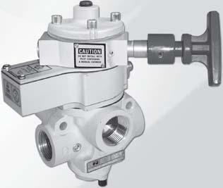
57 CONTROLS SAETY EXHAUST (DUMP) SAETY EXHAUST/ENERGY ISOLATION SENSING VALVES SV7 SERIES
58 SENSING VALVES KEY EATURES Senses internal position & state Electrical feedback via DPST switch ( Double-Pole Single-Throw) Directly operated safety-rated force-guided positive-break status switch (DPST) Poppet construction for near zero leakage & dirt tolerance A diagnostic coverage (DC) of 90% can be obtained by monitoring the safety switch status Explosion proof solenoid pilot available, for more information consult ROSS DESCRIPTION AVAILALE INLET PORT SIZES UNCTIONS VALVE TYPE/SERIES Spool & Sleeve Poppet /8 / /8 / / ¼ ½ ½ / / / / 5/ Single 5/ Double 5/ Closed Center 5/ Open Center 5/ Pressure Center Max low (Cv) Solenoid Control Pressure Controlled Page / SV7 Series / SV7 Series SV7 Series with Lockout Valve Air Entry Packages.0
59 Sensing Valves Safety Exhaust (Dump) Designed for External Monitoring Solenoid Pilot Controlled SV7 Series -Way -Position Valves Size, ody Size Valve Model Number* C V - Weight lb (kg) / / SV7NC0507PSAA** (.) / / SV7NC05507PSAA** 9.6 (.) / SV7NC05607PSAA** 9.6 (.) ¼ SV7NC07607PSAA** 8. (.7) ¼ ¼ SV7NC07707PSAA** 9 8. (.7) ½ ¼ SV7NC07807PSAA** 9 8. (.7) PV * NPT port threads. or SPP threads, replace N in the model number with a D, e.g., SV7DC0507PSAAA. ** Insert voltage code: A =0-0 volts, 50/60 Hz; D = volts DC;.e.g., SV7NC0507PSAAA. or other voltages, consult ROSS. Valve Dimensions inches (mm) ody Size / PV (pressure verification) 9. (5) Y- (pilot exhaust) -pin Mini connector X- (/8 external pilot supply) X Ø 0. (8.0) 5-pin M connector ody Size ¼.0 (0) /8 Pilot exhaust port Y- X Ø 0. (8.0).6 () / Electrical conduit port /8 External pilot supply port X 5-pin M connector (inlet) { (outlet) on opposite side} 0.60 (5).5 (8).5 () 5.7 (5).7 (69).80 (6) (inlet) [ (outlet on opposite site].5 (8).5 (9).8 ().0 (8).66 (8) 6.9 (65) PV (pressure verification).09 (78).09 (0).78 (5) ACCESSORIES & OPTIONS Pressure Switches Kit Number* Length meters (feet) 9H77 (.) 0H77 0 (.8) * Cable has one connector. Connection Type Model Number* Threads EN orm A 586A86 Preassembled Wiring Kits /8 NPT M 5A0 /8 NPT *Pressure switch closes on falling pressure of 5 psig (0. bar). EN Connector Pinout Open Common Closed Ground M Connector Pinout Pin Open Pin Common Pin Not Used Pin Closed Indicator Light Kits Kit Number volts DC 0-0 volts AC Hz 86K87-W 86K87-Z These kits include two cables with a cord grip on each cable. One cable has a -pin MINI connector for the solenoid, and one has a 5-pin M (Micro) connector for the sensing switch. Pop-Up Indicator RN PIN Solenoid Cable with -pin MINI Connector Manual Override Kits UTTON Type Locking Type Model Number* LUSH Non-Locking 790K87 Locking 79K87 EXTENDED Non-Locking 79K87 EXTENDED with PALM Non-Locking 98H87 RN LUE GRN/YEL Model Number** 988A0 ** /8 NPT port threads. LUE PIN GRN/YEL (GROUND) PIN LUE LK PIN PIN Sensing Switch Cable with 5-pin M Connector LUE RN LK WHT GRN/YEL Current/Voltage Max..5 A /0 VAC WHT PIN RN PIN GRY PIN 5 Integrated Double-Pole Single-Throw Switch (DPST) Switch States Contact conditions during switch travel (0 to 6 mm). or valves basic size / & -/, the DPST switch is actuated whenever the valve is not in the normal home position. Construction: Poppet. Mounting Type: In-Line. Solenoid Pilot: AC or DC power. Rated for continuous duty. Standard Voltages: volts DC; 0-0 volts AC, 50/60 Hz. Power Consumption: 87 VA inrush, 0 VA holding on 50 or 60 Hz; watts on DC. Ambient Temperature: 0 to 0 ( to 50 C). Media Temperature: 0 to 75 ( to 80 C). low Media: iltered air. Inlet Pressure: 0 to 50 psig (.8 to 0. bar). Pilot Pressure: Must be equal to or greater than inlet pressure. STANDARD SPECIICATIONS (for valves on this page): Switch Current/Voltage Max.:.5 A/0 volts AC. Switch Current/Voltage Min.: 50 ma/ volts DC. NOTE: Electrical life of switch varies with conditions and voltage; rated in excess of 5 million cycles. unctional Safety Data: Category PL d; 0D: Valve - 0,000,000, Switch,000,000; PHD:.5x0-7 ; MTTD: 98.5 (n op: 760); DC (obtained by monitoring safety switch status): 90%; ROSS recommends testing the switch function and sealing for load holding valves every 8 hours. Vibration/Impact Resistance: Calculated to S EN Rev. 0/0/7.
 / / SV7NC05507PSAA** 7.7.5 (.0) / SV7NC05607PSAA** 8.5 (.0) ½ ¼ SV7NC07607PSAA** 7.8 (.5) ¼ ½ ¼ SV7NC07707PSAA** 0 7.8 (.5) ½ ½ ¼ SV7NC07807PSAA** 0 7.8 (.5) ½ ½ SV7NC09807PSAA** 68 70 8.")
 ody Size / ody Size ¼ PV (pressure verification) 9.")
60 Sensing Valves Safety Exhaust (Dump) Designed for External Monitoring Solenoid Pilot Controlled SV7 Series -Way -Position Valves Size ody Valve Model C V, Size Number* - - Weight lb (kg) / / SV7NC0507PSAA** (.0) / / SV7NC05507PSAA** (.0) / SV7NC05607PSAA** 8.5 (.0) ½ ¼ SV7NC07607PSAA** 7.8 (.5) ¼ ½ ¼ SV7NC07707PSAA** (.5) ½ ½ ¼ SV7NC07807PSAA** (.5) ½ ½ SV7NC09807PSAA** (8.) ½ SV7NC09907PSAA** (8.) ½ ½ SV7NC09957PSAA** (8.) PV * NPT port threads. or SPP threads, replace N in the model number with a D, e.g., SV7DC0507PSAAA. ** Insert voltage code: A =0-0 volts, 50/60 Hz; D = volts DC;.e.g., SV7NC0507PSAAA. or other voltages, consult ROSS. Valve Dimensions inches (mm) ody Size / ody Size ¼ PV (pressure verification) 9.6 () 5.7 (5) Y- (pilot exhaust) (exhaust) -pin Mini connector 5-pin M connector X O 0. (8.0) (inlet) [ (outlet on opposite site].59 (9) X- (/8 external pilot supply) PV (pressure verification).0 (0) 6.8 (7) Y- (pilot exhaust) (exhaust) -pin Mini connector 5-pin M connector X O 0. (8.0) (inlet) [ (outlet on opposite site].89 () X- (/8 external pilot supply) ody Size.8 (00) (exhaust) X Ø 0.5 (.5) X- (/8 external pilot supply) -pin Mini connector 5-pin M connector 8.6 (9) PV (pressure verification) 6. (6) (inlet) [ (outlet on opposite site] STANDARD SPECIICATIONS (for valves on this page): Construction: Poppet. Mounting Type: In-Line. Solenoid Pilot: AC or DC power. Rated for continuous duty. Standard Voltages: volts DC; 0-0 volts AC, 50/60 Hz. Power Consumption: 87 VA inrush, 0 VA holding on 50 or 60 Hz; watts on DC. Ambient Temperature: 0 to 0 ( to 50 C). Media Temperature: 0 to 75 ( to 80 C). low Media: iltered air. Inlet Pressure: 0 to 50 psig (.8 to 0. bar). Pilot Pressure: Must be equal to or greater than inlet pressure. Switch Current/Voltage Max.:.5 A/0 volts AC. Switch Current/Voltage Min.: 50 ma/ volts DC. NOTE: Electrical life of switch varies with conditions and voltage; rated in excess of 5 million cycles. unctional Safety Data: Category PL d; 0D: Valve - 0,000,000, Switch,000,000; PHD:.5x0-7 ; MTTD: 98.5 (n op: 760); DC (obtained by monitoring safety switch status): 99%, ; ROSS recommends testing the switch function and sealing for load holding valves every 8 hours. Vibration/Impact Resistance: Calculated to S EN , ROSS CONTROLS. All Rights Reserved. Rev. 0/0/7
61 Accessories & Options Safety Exhaust (Dump) SV7 Series Silencers Thread Model Number* Avg. Size Type NPT Threads SPT Threads C V Male 5500A600 D5500A600.6 ½ emale 5500A800 D5500A ½ emale 5500A900 D5500A Pressure Range: 0 to 00 psig (0 to 0.7 bar) maximum. low Media: iltered air. size thru ½ size ½ Pressure Switches Connection Type Model Number* Threads EN orm A 586A86 /8 NPT M 5A0 /8 NPT *Pressure switch closes on falling pressure of 5 psig (0. bar). EN Connector Pinout Open Common Closed Ground M Connector Pinout Pin Open Pin Common Pin Not Used Pin Closed Pop-Up Indicator Model Number** 988A0 ** /8 NPT port threads. Indicator Light Kits Manual Overrides volts DC 86K87-W Kit Number 0-0 volts AC Hz 86K87-Z Indicator Light lush utton Locking Type Kit Number Non-Locking 790K87 Locking 79K87 Extended utton Locking Type Kit Number Non-Locking 79K87 Extended utton with Palm Locking Type Kit Number Non-Locking 98H87 Preassembled Wiring Kits These kits include two cables with a cord grip on each cable. One cable has a -pin MINI connector for the solenoid, and one has a 5-pin M (Micro) connector for the sensing switch. Kit Number* Length meters (feet) 9H77 (.) 0H77 0 (.8) * Cable has one connector. RN PIN Solenoid Cable with -pin MINI Connector RN LUE GRN/YEL LUE PIN GRN/YEL (GROUND) PIN LUE LK PIN PIN Sensing Switch Cable with 5-pin M Connector for valves basic size / &¼ LUE RN LK WHT GRN/YEL Current/Voltage Max..5 A /0 VAC WHT PIN RN PIN GRY PIN 5 LUE LK PIN PIN Sensing Switch Cable with 5-pin M Connector for valves basic size GRN/YEL Current/Voltage Max..5 A /0 VAC WHT PIN RN PIN GRY PIN 5 Integrated Double-Pole Single-Throw Switch (DPST) Switch States Contact conditions during switch travel (0 to 6 mm). or basic size / & -/ or basic size or valves basic size / & -/, the DPST switch is actuated whenever the valve is not in the normal home position. or valves basic size, the DPST switch is only actuated whenever the valve is in the normal home position. Rev. 0/0/7.5
62 Sensing Valves Designed for External Monitoring Pressure Controlled Safety Exhaust (Dump) SV7 Series -Way -Position Valves Size ody C Valve Model Number* V Weight, Size - lb (kg) / / SV7NC0505ASAA 7.7. (.6) / / SV7NC05505ASAA 9. (.6) / SV7NC05605ASAA 9. (.6) ¼ SV7NC07605ASAA 6.7 (.0) ¼ ¼ SV7NC07705ASAA (.0) ½ ¼ SV7NC07805ASAA (.0) PV * NPT port threads. or SPP threads, replace N in the model number with a D, e.g., SV7ND0505ASAA. Valve Dimensions inches (mm) PV (pressure / Signal / Signal verification) 5-pin M connector 6. (55) 5.7 (5) ody Size / X O 0. (8.0) (inlet) [ (outlet) on opposite site]. (79) PV (pressure / Signal / Signal verification) 5-pin M connector 8.7 (0) 6.8 (7) ody Size ¼ X Ø 0. (8.0) (inlet) [ (outlet) on opposite site]. (05) Not intended as a pressure trapping device; Please see Pilot Operated Check Sensing Valves, pages.-.6. ACCESSORIES & OPTIONS Pressure Switches Preassembled Wiring Kits Kit Number* Connection Type EN orm A Length meters (feet) H77 (.) H77 0 (.8) * Cable has one connector. Model Number* 586A86 Threads /8 NPT M 5A0 /8 NPT *Pressure switch closes on falling pressure of 5 psig (0. bar). EN Connector Pinout Open Common Closed Ground M Connector Pinout Pin Open Pin Common Pin Not Used Pin Closed Pop-Up Indicator These kits include one cable with a cord grip. Cable has a 5-pin M (Micro) connector for the sensing switch. Model Number** 988A0 ** /8 NPT port threads. LUE LK PIN PIN Sensing Switch Cable with 5-pin M Connector LUE RN LK WHT GRN/YEL Current/Voltage Max..5 A /0 VAC WHT PIN RN PIN GRY PIN 5 Integrated Double-Pole Single-Throw Switch (DPST) Switch States Contact conditions during switch travel (0 to 6 mm). or valves basic size / & -/, the DPST switch is actuated whenever the valve is not in the normal home position. STANDARD SPECIICATIONS (for valves on this page): Construction: Poppet. Mounting Type: In-Line. Ambient Temperature: 0 to 0 ( to 50 C). Media Temperature: 0 to 75 ( to 80 C). low Media: iltered air. Inlet Pressure: 0 to 50 psig (.8 to 0. bar). Pilot Pressure: Must be equal to or greater than inlet pressure. Switch Current/Voltage Max.:.5 A/0 volts AC. Switch Current/Voltage Min.: 50 ma/ volts DC. NOTE: Electrical life of switch varies with conditions and voltage; rated in excess of 5 million cycles. unctional Safety Data: Category PL d; 0D: Valve - 0,000,000, Switch,000,000; PHD:.5x0-7 ; MTTD: 98.5 (n op: 760); DC (obtained by monitoring safety switch status): 90%; ROSS recommends testing the switch function and sealing for load holding valves every 8 hours. Vibration/Impact Resistance: Calculated to S EN , ROSS CONTROLS. All Rights Reserved. Rev. 0/0/7
63 Sensing Valves Designed for External Monitoring Pressure Controlled Safety Exhaust (Dump) SV7 Series -Way -Position Valves Size ody C Valve Model Number* V, Size - - Weight lb (kg) / / SV7NC0505ASAA (.5) / / SV7NC05505ASAA 7.7. (.5) / SV7NC05605ASAA 8. (.5) ½ ¼ SV7NC07605ASAA 6. (.9) ¼ ½ ¼ SV7NC07705ASAA 0 6. (.9) ½ ½ ¼ SV7NC07805ASAA 0 6. (.9) ½ ½ SV7NC09805ASAA (7.8) ½ SV7NC09905ASAA (7.8) ½ ½ SV7NC09955ASAA (7.8) PV * NPT port threads. or SPP threads, replace N in the model number with a D, e.g., SV7DC0505ASAA. Valve Dimensions inches (mm) ody Size / PV (pressure / Signal verification) 6. (6) 5.7 (5) X O 0. (8.0) (exhaust) 5-pin M connector (inlet) [ (outlet) on opposite site)] / Signal.6 (9) PV (pressure / Signal verification) 8.8 () ody Size ¼ ody Size XØ 0. (8.0) / Signal 5-pin M connector (exhaust) (inlet) [ (outlet) 6.8 (7) on opposite site)].9 () (exhaust).8 (00) 8.6 (9) (inlet) [ (outlet on opposite site] X Ø 0.5 (.5) PV (pressure verification) / Signal 6. (6) 5-pin M connector ACCESSORIES & OPTIONS Silencers Thread Model Number* Avg. Size Type NPT Threads SPT Threads C V Male 5500A600 D5500A600.6 ½ emale 5500A800 D5500A ½ emale 5500A900 D5500A Pressure Range: 0 to 00 psig (0 to 0.7 bar) maximum. low Media: iltered air. size & ½ Preassembled Wiring Kits Kit Number* Length meters (feet) H77 (.) H77 0 (.8) * Cable has one connector. size ½ These kits include one cable with a cord grip. Cable has a 5-pin M (Micro) connector for the sensing switch. Pressure Switches Connection Type EN orm A LUE LK PIN PIN Sensing Switch Cable with 5-pin M Connector for valves basic size / &¼ Model Number* 586A86 LUE RN LK WHT GRN/YEL Current/Voltage Max..5 A /0 VAC Threads /8 NPT M 5A0 /8 NPT *Pressure switch closes on falling pressure of 5 psig (0. bar). Pop-Up Indicator Model Number** 988A0 ** /8 NPT port threads. WHT PIN RN PIN GRY PIN 5 LUE LK PIN PIN Sensing Switch Cable with 5-pin M Connector for valves basic size EN Connector Pinout Open Common Closed Ground M Connector Pinout Pin Open Pin Common GRN/YEL Current/Voltage Max..5 A /0 VAC Pin Not Used Pin Closed WHT PIN RN PIN GRY PIN 5 Integrated Double-Pole Single-Throw Switch (DPST) Switch States Contact conditions during switch travel (0 to 6 mm). or basic size / & -/ or basic size or valves basic size / & -/, the DPST switch is actuated whenever the valve is not in the normal home position. or valves basic size, the DPST switch is only actuated whenever the valve is in the normal home position. Construction: Poppet. Mounting Type: In-Line. Ambient Temperature: 0 to 0 ( to 50 C). Media Temperature: 0 to 75 ( to 80 C). low Media: iltered air. Inlet Pressure: 0 to 50 psig (.8 to 0. bar). Pilot Pressure: Must be equal to or greater than inlet pressure. Switch Current/Voltage Max.:.5 A/0 volts AC. Switch Current/Voltage Min.: 50 ma/ volts DC. STANDARD SPECIICATIONS (for valves on this page): NOTE: Electrical life of switch varies with conditions and voltage; rated in excess of 5 million cycles. unctional Safety Data: Category PL d; 0D: Valve - 0,000,000, Switch,000,000; PHD:.5x0-7 ; MTTD: 98.5 (n op: 760); DC (obtained by monitoring safety switch status): 99% ; ROSS recommends testing the switch function and sealing for load holding valves every 8 hours. Vibration/Impact Resistance: Calculated to S EN Rev. 0/0/7.7
 / / SV7NCL507PSAA** 6. 9. 5.5 (.5) / / SV7NCL5507PSAA** 7.7 5.5 (.5) / SV7NCL5607PSAA** 8 5.5 (.5) ½ ¼ SV7NCL7607PSAA** 9.0 (.0) ¼ ½ ¼ SV7NCL7707PSAA** 0 9.0 (.0) ½ ½ ¼ SV7NCL7807PSAA** 0 9.")
64 Sensing Valves with Lockout L-O-X Control Designed for External Monitoring Solenoid Pilot Controlled Safety Exhaust/Energy Isolation SV7 Series -Way -Position Valves Size ody C Valve Model Number* V Weight, Size - - lb (kg) / / SV7NCL507PSAA** (.5) / / SV7NCL5507PSAA** (.5) / SV7NCL5607PSAA** (.5) ½ ¼ SV7NCL7607PSAA** 9.0 (.0) ¼ ½ ¼ SV7NCL7707PSAA** (.0) ½ ½ ¼ SV7NCL7807PSAA** (.0) X PV Y Y * NPT port threads. or SPP threads, replace N in the model number with a D, e.g., SV7DCL507PSAAA. **Insert voltage code: A =0-0 volts AC, 50/60 Hz; D for volts DC; e.g., SV7NCL507PSAAA. or other voltages, consult ROSS. Valve Dimensions inches (mm) PV (pressure verification) 0. (6).0 (77) 0.6 (5).5 (8) 8.06 (05) ody Size / /8 Pilot exhaust port Y- exhaust Ø 0. (9) /8 External pilot supply port X- (inlet) { (outlet) on opposite side} 6.70 (70).0 (5) Ø 0.5 ().5 (9) /8 Pilot exhaust port Y- PV (pressure verification).50 ().65 (8) 8.06 (05) ody Size ¼ (exhaust) (inlet) { (outlet) on opposite side} /8 External pilot supply port X (7) ACCESSORIES & OPTIONS Silencers size & ½ size ½ Size Thread Type Multiple Lockout Device Model Number 56A0 Preassembled Wiring Kits These kits include two cables with a cord grip on each cable. One cable has a -pin MINI connector for the solenoid, and one has a 5-pin M (Micro) connector for the sensing switch. Model Number* NPT Threads SPT Threads Kit Number* Avg. C V Male 5500A600 D5500A600.6 ½ emale 5500A800 D5500A ½ emale 5500A900 D5500A Pressure Range: 0 to 00 psig (0 to 0.7 bar) maximum. low Media: iltered air. Indicator Light Kits Kit Number volts DC 0-0 volts AC Hz 86K87-W 86K87-Z Length meters (feet) 9H77 (.) 0H77 0 (.8) * Cable has one connector. Pressure Switches Pop-Up Indicator Connection Type EN orm A Model Number** 988A0 ** /8 NPT port threads. RN PIN Solenoid Cable with -pin MINI Connector RN Model Number* 586A86 LUE GRN/YEL LUE PIN GRN/YEL (GROUND) PIN Threads /8 NPT M 5A0 /8 NPT *Pressure switch closes on falling pressure of 5 psig (0. bar). EN Connector Pinout Open Common Closed Ground LUE LK PIN PIN Sensing Switch Cable with 5-pin M Connector M Connector Pinout Pin Open Pin Common LUE RN LK WHT GRN/YEL Current/Voltage Max..5 A /0 VAC Pin Not Used Pin Closed WHT PIN RN PIN GRY PIN 5 Integrated Double-Pole Single-Throw Switch (DPST) Switch States Contact conditions during switch travel (0 to 6 mm). or valves basic size / & -/, the DPST switch is actuated whenever the valve is not in the normal home position. Construction: Poppet. Mounting Type: In-Line. Solenoid Pilot: AC or DC power. Rated for continuous duty. Standard Voltages: volts DC; 0-0 volts AC, 50/60 Hz. Power Consumption: 87 VA inrush, 0 VA holding on 50 or 60 Hz; watts on DC. Ambient Temperature: 0 to 0 ( to 50 C). Media Temperature: 0 to 75 ( to 80 C). low Media: iltered air. Inlet Pressure: 0 to 50 psig (.8 to 0. bar). Pilot Pressure: Must be equal to or greater than inlet pressure. STANDARD SPECIICATIONS (for valves on this page): Switch Current/Voltage Max.:.5 A/0 volts AC. Switch Current/Voltage Min.: 50 ma/ volts DC. Manual Override: lush; rubber, non-locking. NOTE: Electrical life of switch varies with conditions and voltage; rated in excess of 5 million cycles. unctional Safety Data: Category PL d; 0D: Valve - 0,000,000, Switch,000,000; PHD:.5x0-7 ; MTTD: 98.5 (n op: 760); DC (obtained by monitoring safety switch status): 99% ; ROSS recommends testing the switch function and sealing for load holding valves every 8 hours. Vibration/Impact Resistance: Calculated to S EN , ROSS CONTROLS. All Rights Reserved. Rev. 0/0/7
 / / SV7NCL505ASAA 6. 9.. (.0) / / SV7NCL5505ASAA 7.7. (.0) / SV7NCL5605ASAA 8. (.0) ½ ¼ SV7NCL7605ASAA 7. (.) ¼ ½ ¼ SV7NCL7705ASAA 0 7. (.) ½ ½ ¼ SV7NCL7805ASAA 0 7. (.) * NPT port threads.")
65 Sensing Valves with Lockout L-O-X Control Safety Exhaust/Energy Isolation Designed for External Monitoring Pressure Controlled SV7 Series -Way -Position Valves Size ody C Valve Model Number* V, Size - - Weight lb (kg) / / SV7NCL505ASAA (.0) / / SV7NCL5505ASAA 7.7. (.0) / SV7NCL5605ASAA 8. (.0) ½ ¼ SV7NCL7605ASAA 7. (.) ¼ ½ ¼ SV7NCL7705ASAA 0 7. (.) ½ ½ ¼ SV7NCL7805ASAA 0 7. (.) * NPT port threads. or SPP threads, replace N in the model number with a D, e.g., SV7DCL505ASAA. Y X PV Valve Dimensions inches (mm) ody Size / (exhaust) ody Size ¼ PV (pressure verification) PV (pressure verification) Ø 0.5 () 7. (8).0 (77) 0.6 (5) Ø 0. (9).5 exhaust (8) 8.06 (05) (inlet) { (outlet) on opposite side} 6.70 (70) 0.09 (56).50 ().5 (9).65 (8) 8.06 (05) (inlet) { (outlet) on opposite side} 6.80 (7) ACCESSORIES & OPTIONS Silencers Preassembled Wiring Kits Kit Number* Length meters (feet) H77 (.) H77 0 (.8) * Cable has one connector. Thread Model Number* Avg. Size Type NPT Threads SPP Threads C V Male 5500A600 D5500A600.6 ½ emale 5500A800 D5500A Pressure Range: 0 to 00 psig (0 to 0.7 bar) maximum. low Media: iltered air. Multiple Lockout Device Model Number 56A0 These kits include one cable with a cord grip. Cable has a 5-pin M (Micro) connector for the sensing switch. Pressure Switches LUE LK PIN PIN Sensing Switch Cable with 5-pin M Connector LUE RN Connection Type LK WHT GRN/YEL Current/Voltage Max..5 A /0 VAC EN orm A WHT PIN RN PIN GRY PIN 5 Model Number* 586A86 Threads /8 NPT M 5A0 /8 NPT *Pressure switch closes on falling pressure of 5 psig (0. bar). EN Connector Pinout Open Common Closed Ground Pin Open Pop-Up Indicator Pin Common Model Number** 988A0 ** /8 NPT port threads. M Connector Pinout Pin Not Used Pin Closed Integrated Double-Pole Single-Throw Switch (DPST) Switch States Contact conditions during switch travel (0 to 6 mm). or valves basic size / & -/, the DPST switch is actuated whenever the valve is not in the normal home position. Construction: Poppet. Mounting Type: In-Line. Ambient Temperature: 0 to 0 ( to 50 C). Media Temperature: 0 to 75 ( to 80 C). low Media: iltered air. Inlet Pressure: 0 to 50 psig (.8 to 0. bar). Pilot Pressure: Must be equal to or greater than inlet pressure. Switch Current/Voltage Max.:.5 A/0 volts AC. Switch Current/Voltage Min.: 50 ma/ volts DC. STANDARD SPECIICATIONS (for valves on this page): NOTE: Electrical life of switch varies with conditions and voltage; rated in excess of 5 million cycles. unctional Safety Data: Category PL d; 0D: Valve - 0,000,000, Switch,000,000; PHD:.5x0-7 ; MTTD: 98.5 (n op: 760); DC (obtained by monitoring safety switch status): 99% ; ROSS recommends testing the switch function and sealing for load holding valves every 8 hours. Vibration/Impact Resistance: Calculated to S EN Rev. 0/0/7.9

, Number* Type - - Length Width Depth / RC08-09** R 6. 9..80 (7.9).00 (79.0) 6.60 (67.7) Cat- with SV7 / RC08L-09** RL 6. 9..80 (7.9).00 (79.0) 6.60 (67.7) * NPT pressure port threads.")
66 Air Entry Packages with SV7 Series Sensing Valves Safety Exhuast/Energy Isolation RC Series SV7 Sensing Valves, Manual Lockout L-O-X Valves with Integrated ilter/regulator Pre-engineered panel-mounted design with air entry via filter and regulator R, or filter, regulator, and lubricator RL. Includes / Closed Sensing Valve which senses poppet position and state. Electrical feedback via DPST switch (Double-Pole Single-Throw). Applications include Air Dump and Trapped-Pressure Release. Mounting plate included. Air Entry Combination Size Model Air Entry C V Dimensions inches (mm), Number* Type - - Length Width Depth / RC08-09** R (7.9).00 (79.0) 6.60 (67.7) Cat- with SV7 / RC08L-09** RL (7.9).00 (79.0) 6.60 (67.7) * NPT pressure port threads. ** Specify voltage when ordering. Insert voltage code: W = volts DC; Z = 0-0 volts AC, 50/60 Hz; e.g., RC08-09W. M connectors available, consult ROSS. Standard Air Entry Packages supplied with metal bowl and manual drain. or automatic drain insert an A before the dash (-) in the model number, e.g., RC08A-09. Custom designs available, consult ROSS. Explosion proof solenoid pilot available, for more information consult ROSS. SV7 Sensing Valves, Manual Lockout L-O-X Valves with ilter and Regulator Pre-engineered panel-mounted design with air entry via filter and regulator R, or filter, regulator, and lubricator RL Includes / Closed Sensing Valve. Applications include Air Dump and Trapped-Pressure Release. Mounting plate included. Air Entry Combination Size Model Air Entry C V Dimensions inches (mm), Number* Type - - Length Width Depth / / RC08-06** R (585).8 (6) 6.7 (7) / / RC08L-06** RL (585).8 (6) 6.7 (7) Cat- with SV7 / / RC-06** R (7) 7.0 () 9.5 () / / RCL-06** R (585).8 (6) 6.7 (7) RC6-06** RL (585).8 (6) 6.7 (7) RC6L-06** RL (808) 7.0 () 9.5 () * NPT pressure port threads. ** Specify voltage when ordering. Insert voltage code: W = volts DC; Z = 0-0 volts AC, 50/60 Hz; e.g., RC08-06W. M connectors available, consult ROSS. Standard Air Entry Packages supplied with metal bowl and manual drain. or automatic drain insert an A before the dash (-) in the model number, e.g., RC08A-06. Custom designs available, consult ROSS. Explosion proof solenoid pilot available, for more information consult ROSS..0 07, ROSS CONTROLS. All Rights Reserved. Rev. 0/0/7


67
68


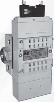
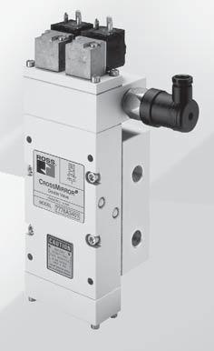
69 CONTROLS SAE CYLINDER RETURN CONTROL RELIALE DOULE VALVES RSE, CROSSMIRROR CM & 77 SERIES


70 5/ RSe Series KEY EATURES Rapid response for minimum actuating time Status indicator provides valve condition (ready-to-run) feedback Position sensors for valve fault monitoring external monitoring device required Well-proven spool valve design for reliable, smooth function External pilot supply port is a standard feature ase-mounting design 5/ CROSSMIRROR Series KEY EATURES Can be used as / Closed or / Open valve function by plugging the unused outlet port Self-contained dynamic monitoring system; no additional monitoring required Valve fault results in a lockout condition and prevents unintentional reset with removal of air or electricity Reset can be electrical solenoid or remote pneumatic signal Status indication switch (ready-to-run) to inform machine controller of valve condition ase mounted, stainless steel spool valve construction Manifoldable for multi valve applications Includes non-clogging safety mufflers; for applications requiring ported exhaust, consult ROSS These valves are not designed for controlling clutch/brake mechanisms on mechanical power presses. 5 Double Valves Designed for External Monitoring CROSSMIRROR Double Valves with Dedicated Reset CROSSMIRROR Double Valves with Automatic Reset OPERATION AVAILALE PORT SIZES MAX. LOW Cv RESET VALVE TYPE VALVE Size SERIES Page /8 / /8 / / /8 / /8 / / DOULE VALVES Designed for External Monitoring with Proximity Sensors RSe DOULE VALVES with Dedicated Reset with Pressure Switch CM...9 without Pressure Switch CM Components for MANIOLD ASSEMLIES - Solenoid Pilot Controlled AIR PILOT SOLENOID Valves, Manifold ases and End Stations for Manifold Assemblies.8 with Pressure Switch CM...9 without Pressure Switch CM Components for MANIOLD ASSEMLIES - Pressure Controlled Valves, Manifold ases and End Stations for Manifold Assemblies. DOULE VALVES with Automatic Reset with Pressure Switch without Pressure Switch PRESSURE CONTROLLED with Pressure Switch without Pressure Switch REMOTE SOLENOID
 RSe 6 E D A 0 A P Series Type/unction 5/ 6 External Revision Monitoring Comingeedback Automatic Sensor Level Reset Thread Voltage Soon!")
71 Control Reliable Double Valves Designed for External Monitoring RSe Series Safe Cylinder Return 5/ Redundant Double Valve Sub-base Mounted HOW TO ORDER (Choose your options (in red) to configure your valve model number.) RSe 6 E D A 0 A P Series Type/unction 5/ 6 External Revision Monitoring Comingeedback Automatic Sensor Level Reset Thread Voltage Soon! SPP D Inlet Outlet volts DC A NPT N /8 /8 0 / / 0 / / 0 Sensor Sensor Output PNP P Size 5/ Valves C V Weight lb (Kg) / (.) / (.7) / (.99) (Certification pending) (Certification pending) (Certification pending) HSM xxxxxx Sicherheit geprüft tested safety The 5/ RSe Series valve is designed to control the direction of air flow into and out of a double-acting cylinder or other pneumatic actuator in order to drive the cylinder forward or backward to suit the requirements of the machine operation. However, the RSe Series does this with the same level of control expected of the machine s/system s safety circuit. The safety function of the RSe Series valve is to return the cylinder/actuator to its home safe position whenever a fault occurs within the valve. Such a monitoring system must be capable of inhibiting the operation of the valve. The RSe Series valves are designed for external monitoring for safe, redundant operation of the valves. The RSe Series valves are constructed of redundant, spool type valves, and have an overall function of a single solenoid pilot-operated, spring return valve. Each single valve in the RSe Series is equipped with a PNP proximity sensor. Monitoring both of these sensors on each actuation and de-actuation of the RSe Series valve provides a diagnostic coverage of 99%. Monitoring of these sensors is to be done by an external monitoring system. Simplified Schematics STANDARD SPECIICATIONS (for valves on this page): Construction: Spool and sleeve. Mounting Type: ase. Actuation: Solenoid pilot operated with spring return. One solenoid per valve element both to be operated synchronously. Solenoid: Version as per VDE Rated for continuous duty. Electrical connection according to EN orm C. Enclosure rating according to DIN IP 65. Standard Voltages: volts DC. Power Consumption (each solenoid):. watts on DC. Proximity Sensors ( per valve): PNP. Current Consumption (each sensor): <ma. Ambient/Media Temperature: 0 to 0 ( to 50 C). low Media: Compressed, filtered air according to ISO 857- Class 7::. Inlet Pressure: With internal pilot supply: to 5 psig ( to 0 bar). With external pilot supply: 0 to 5 psig (0 to 0 bar). Pilot Pressure: Must be equal to or greater than inlet pressure. Mounting Orientation: Any, preferably vertical. Monitoring: Dynamic, cyclical, external with customer supplied equipment. Monitoring should check state of both valve pressure sensors with any and all changes in state of valve control signals. unctional Safety Data: Pending. This valve is not designed for controlling clutch/brake mechanisms on mechanical power presses. Rev. 0/0/7.
 0.59 (5.0) 0.5 (.5) 0. (6.0).8 (7.5) 0. (6.00). (9.0).67 (.5) 0.5 (9.0).87 0.97 (7.5) (.5) 0.5 0.87 0.78 0.9 (9.0) (.)(9.9)(.75) External Pilot Supply /8 NPT Size /. (8.0) 0. (5.5). (.0).97 (50.0).6 (.")
72 Control Reliable Double Valves Designed for External Monitoring Safe Cylinder Return RSe Series Size /8.96 (75.0).97 (00.8).67 (67.8).8 (0.0) Inlet Exhaust Exhaust Valve Dimensions inches (mm).67 (9.) 0.59 (5.0) 0.5 (.5) 0. (6.0).8 (7.5) 0. (6.00). (9.0).67 (.5) 0.5 (9.0) (7.5) (.5) (9.0) (.)(9.9)(.75) External Pilot Supply /8 NPT Size /. (8.0) 0. (5.5). (.0).97 (50.0).6 (.0) 0. (.0).7 (.5).06 (7.0).8 Inlet (0.0) Exhaust.99 (76.0) 0. (.0).8 (0.0) Exhaust (.5)(6.5).99 (0.) 0.55 (.0) 0.8 (.0) 0.6 (6.55) External Pilot Supply /8 NPT.89 (98.9) 0.8 (7.0) Ø0.6 (6.5) 0.0 (7.5).6 (.0) Size /.66 (9.0) 6.8 (7.0) Inlet Exhaust.56 (5.9) Exhaust External Pilot Supply /8 NPT.56 (5.9) 0.8 (7.0) 0. (6.0).8 (6.5) 0. (0.).78 (96.0).65 (.0).7 (69.5).6 (.5) 0.67 (7.0) 0.67 (7.0).89 (8.). (.8).5 (8.).08 (7.5) 0. (.0) ACCESSORIES & OPTIONS Silencers Size Thread Type Model Number Avg. C V Dimensions inches (mm) NPT Threads SPT Threads A Weight lb (kg) /8 Male 5500A00 D5500A ().0 (5) 0. (0.) / Male 5500A00 D5500A (). (55) 0. (0.) / Male 5500A00 D5500A00.7. ().6 (9) 0. (0.) A Pressure Range: 0 to 00 psig (0 to 0.7 bar) maximum. low Media: iltered air. Electrical Connectors Connection Solenoid Electrical Connector orm DIN EN orm C Electrical Connector Type Cord Length meters (feet) Cord Diameter Without Light Model Number Lighted Connector Volts DC Prewired Connector (8 gauge) (0) 8-mm 9K77 50K77-W DIN 650 orm C Connector Only 5K77 5K77-W eedback Sensor M8 Connector (sensing) Prewired Connector (6.5) CAUTIONS: Do not use electrical connectors with surge suppressors, as this may increase valve response time when de-actuating the solenoids. Preassembled Wiring Kits Valve Size Lighted Connector / & 5/ Connector Type EN orm C (solenoids) M8 (sensors) Length meters (feet) (6.5) * Each cable has one connector. Kits include cables for the sensors (M8), and cables (EN orm C) with connector plus a cord grip for each. Solenoid Cables with EN connector RN PIN RN NOT USED LUE PIN GRN/YEL GROUND LUE GRN/YEL Sensor Wiring M8 Connector L+ L- Wire Colors rown lue lack. 07, ROSS CONTROLS. All Rights Reserved. Rev. 0/0/7
 / / 0 /8 /8 0 Valve and ase Assembly With# CM6PNA00** CM6PNA00** 0.8 0.6 0.5. 5.85 (.7) Without CM6PNA00**X CM6PNA00**X 0.")
 * Includes base supplied with NPT port threads. or SPP threads, replace N with a D in the model number, e.g., CM6PDA00AX.** Insert voltage code: A = volts DC; = 0 volts AC, 0 volts AC; e.g., CM6PNA00AX.")
73 CROSSMIRROR Control Reliable Double Valves with Dedicated Reset Solenoid Pilot Controlled Safe Cylinder Return CM Series 5 s, -Way -Position Valve, Pressure Return Sizes asic Pressure Model Number* C V Weight, Size Switch With Remote Reset With Solenoid Reset lb (kg) / / 0 /8 /8 0 Valve and ase Assembly With# CM6PNA00** CM6PNA00** (.7) Without CM6PNA00**X CM6PNA00**X (.) With# CM6PNA0** CM6PNA0** (.6) Without CM6PNA0**X CM6PNA0**X (.) With# CM6PNA** CM6PNA** (6.56) / / Without CM6PNA**X CM6PNA**X (6.6) * Includes base supplied with NPT port threads. or SPP threads, replace N with a D in the model number, e.g., CM6PDA00AX.** Insert voltage code: A = volts DC; = 0 volts AC, 0 volts AC; e.g., CM6PNA00AX. # Valve include pressure switches with DIN type connection, for pressure switches with M type connection consult ROSS. HSM 506 Sicherheit seprüft tested safety ISO 89-:006 Category PL e Valves, Manifold ases, and End Stations for Manifold Assemblies In addition to the manifold, an end station kit with a check valve must be ordered for each assembly. The number of manifolds with a single supply inlet will be limited to the pressure and flow rate of the system. Too many manifolds may result in too large of an internal pressure drop resulting in valve faults. The manifold end station kit with dual inlet check will allow the manifold to be supplied with air from both ends of the assembly. Size, asic Size / / 0 /8 /8 0 / / Pressure Switch or other voltages consult ROSS. Valve without Sub-ase Model Number Manifold ase Model Number# Manifold End Station w/ Check Valve Kit Number## Dual Supply Manifold End Station w/ Check Valves Kit Number## With Remote Reset With Solenoid Reset With* CM6PXA0X** CM6PXA0X** Y95D9 699K86 70K86 Without CM6PXA0X**X CM6PXA0X**X Y95D9 699K86 70K86 With* CM6PXA0X** CM6PXA0X** Y99D9 698K86 700K86 Without CM6PXA0X**X CM6PXA0X**X Y99D9 698K86 700K86 With* CM6PXAX** CM6PXAX** Y955D9 70K86 70K86 Without CM6PXAX**X CM6PXAX**X Y955D9 70K86 70K86 * Valve include pressure switches with DIN type connection, for pressure switches with M type connection consult ROSS. ** Insert voltage code: A = volts DC; = 0 volts AC, 0 volts AC; e.g., CM6PXA0XAX. #NPT port threads. or SPP threads, insert a D after Y in the model number, e.g., YD95D9. ##NPT port threads. or SPP threads, add a D prefix to the model number, e.g., D699K86, D70K86. End Station End Station with Check Valve Manifold ase Explosion proof solenoid pilot available, for more information consult ROSS. 5 STANDARD SPECIICATIONS (for valves on this page): Construction: Double spool and sleeve. Mounting Type: ase mounted. Pilot Solenoid: According to VDE Two solenoids, rated for continuous duty. Standard Voltages/Pilot Solenoids Power Consumption (each solenoid): Size 0: volts DC:. watts on DC. 0 volts AC, 50 Hz: 5. VA; 0 volts AC, 60 Hz: 5.0 VA. Size : volts DC; 0 volts AC, 50 Hz; 0 volts AC, 50/60 Hz. 5.8 watts nominal on AC and DC, 6.5 watts maximum on AC and DC. Enclosure Rating: DIN IP 65. Electrical Connection: Size 0: Connector socket according to EN orm C. Size : Connector socket according to EN orm A. Ambient Temperature: 5 to (-0 to 50 C). Media Temperature: 0 to 75 ( to 80 C). low Media: iltered air. Inlet Pressure: 0 to 50 psig ( to 0 bar). Pressure Switch (Status Indicator) Rating: 5 amps at 50 volts AC, or 5 amps at 0 volts DC. Monitoring: Dynamically, cyclically, internally during each actuating and de-actuating movement. Monitoring function has memory and requires an overt act to reset unit after lockout. Solenoid Reset: Units with solenoid reset include a / solenoid valve. Energize this solenoid momentarily to reset valve after lock-out condition occurs. Remote Reset: Remote signal to be supplied by customer s / valve (connect remote signal line to remote RESET port in valve). Apply signal momentarily to reset valve after fault condition occurs. NOTE: Main solenoids must be off when performing reset procedure. unctional Safety Data: Category PL e; 0D: 0,000,000; PHD: 7.7x0-9 ; MTTD: 0.9 (n op : 6600). Certifications: CE Marked for applicable directives, DGUV Test. Vibration/Impact Resistance: Tested to S EN Meets Standards EN76 and ANSI., Safety requirements for Pneumatic Cylinder Presses and other hazardous pneumatic cylinder applications. This valve is not designed for controlling clutch/brake mechanisms on mechanical power presses. Rev. 0/0/7.5
74 CROSSMIRROR Control Reliable Double Valves with Dedicated Reset Solenoid Pilot Controlled asic Size 0 - Valve and base assembly, with remote reset and with pressure switch. Valve Technical Data CM Series Valve Dimensions inches (mm).7 (0.) VALVE ASSEMLY 5/ CM SERIES.7 (0.9) REMOTE RESET 0.89 (76.6) 0.80(0.) ASE ASSEMLY.00 (76.) asic Size 0 - Valve and base assembly, with solenoid reset and with pressure switch..7 (0.) VALVE ASSEMLY.7 (0.9) REMOTE RESET.9 (.) 0.80 (0.) ASE ASSEMLY.00 (76.) asic Size 0 - Valve and base assembly, with remote reset and without pressure switch. VALVE ASSEMLY.7 (0.) 5/ CM SERIES.5 (85.) REMOTE RESET 8.7 (.0) 0.80 (0.) ASE ASSEMLY.00 (76.) 5 asic Size 0 - Valve and base assembly, with solenoid reset and without pressure switch..7 (0.).5 (85.) VALVE ASSEMLY REMOTE RESET 0. (57.6) 0.80 (0.) ASE ASSEMLY.00 (76.) Dimensions inches (mm) Manifold ase for asic Size 0.66 (9.0).70 (.) (9.) (76.).05 (6.7).60 (9.).00 (76.) 0.70 (7.8).66 (9.0) 0.80 (0.).8 (6.5).05 (6.7) 0.70 (7.8).00 (76.) End Station for asic Size 0 End Station with Check Valve for asic Size 0.66 (9.0).66 (9.0) 0.57(.5).90 (8.).90 (8.).90 (8.).70 (.).7 (6.7).70 (.).6 Rev. 0/0/7
75 CROSSMIRROR Control Reliable Double Valves with Dedicated Reset Solenoid Pilot Controlled asic Size - Valve and base assembly, with remote reset and with pressure switch. Valve Technical Data CM Series Valve Dimensions inches (mm) 5.8 (7.8) VALVE ASSEMLY 5.7 (5.9).79 (.8).7 (9.6) ASE ASSEMLY.6 (0.7) asic Size - Valve and base assembly, with solenoid reset and with pressure switch. 5.8 (7.8) VALVE ASSEMLY 5.7 (5.9).7 (7.).7 (9.6) ASE ASSEMLY.6 (0.7) asic Size - Valve and base assembly, with remote reset and without pressure switch. VALVE ASSEMLY 5.8 (7.8).67 (8.5).9 (9.9).7 (9.6) ASE ASSEMLY.6 (0.7) asic Size - Valve and base assembly, with solenoid reset and without pressure switch. 5 VALVE ASSEMLY 5.8 (7.8).67 (8.5). (.5).7 (9.6) ASE ASSEMLY.6 (0.7) Dimensions inches (mm) Manifold ase for asic Size.6 (0.7) 5.0 (7.5).6 (59.7).8 (.). (6.).8 (.).0 (8.).6 (0.7).58 (0.0) 0.98 (.8).8 (.).58 (0.0).0 (8.).6 (0.7). (8.) End Station for asic Size End Station with Check Valve for asic Size.0 (.0).5 (59.7).8 (.).88 (7.0). (8.) 0.50 (.7).8 (60.).5 (59.7).8 (.) Rev. 0/0/7.7
76 CROSSMIRROR Control Reliable Double Valves with Dedicated Reset Solenoid Pilot Controlled Valve Operation & Options CM Series Normal Operation: The valve is operated by energizing both pilot solenoids simultaneously. This causes both main valve elements to be actuated so that air from inlet port flows to outlet port, but not to port. Air downstream of port is exhausted through port. When the solenoids are de-energized, both valve elements are de-actuated, and air then flows from inlet port to outlet port, but no longer to outlet port. Air downstream of port is exhausted through port 5. On first operation, or after repair, the pilot valve supply circuit and inherent monitoring elements may need to be reset. Valve Locked-out: Whenever the valve elements operate in a sufficiently asynchronous manner, either on actuation or de-actuation, the valve will move to a locked-out position. In the locked-out position, one crossover and its related timing chamber will be exhausted, and the other crossover and its related timing chamber will be fully pressurized. The valve element (side ) that is partially actuated has pilot air available to fully actuate it, but no air pressure on the return piston to fully de-actuate the valve element. The return springs are limited in travel, and can only return the valve elements to the intermediate (locked-out) position. Sufficient air pressure acting on the return pistons is needed to return the valve elements to a fully home position. 5 VALVE Optional Status Indicator Pilot Valve Exh. Pilot Valve Pressure Switch Optional Reset Valve Detecting a Malfunction: If the main valve elements are not both actuated or deactuated synchronously, the valve defaults to the locked-out position so that outlet port receives full inlet pressure, and outlet port is exhausted through port 5. The valve must now be reset to resume normal operation. Resetting the Valve: The valve will remain in the locked-out position, even if the inlet air supply is removed and re-applied. A remote reset signal must be applied to reset the valve. Reset is accomplished by momentarily pressurizing the reset port. Actuation of the reset piston physically pushes the main valve elements to their home position. Actuation of the reset piston also opens the reset poppet, thereby, immediately exhausting pilot supply air, thus, preventing valve operation during reset. De-actuation of reset pistons causes the reset poppets to close and pilot supply timing chambers to fully pressurize. Reset pressure can be applied by a remote / normally closed valve, or from an optional / normally closed solenoid (which includes an integral manual reset button) mounted on the reset adapter. Valve Schematic Reset Status Indicator: The optional status indicator pressure switch will actuate when the main valve is operating normally, and will de-actuate when the main valve is in the locked-out position or inlet pressure is removed. This device is not part of the valve lockout function, but, rather, only reports the status of the main valve. ASE 5 Electrical Connectors asic Valve Size 0 Electrical Connector orm EN orm C Electrical Connector Type Cord Length meters (feet) Cord Diameter Electrical Connector Model Number Without Lighted Connector Light Volts DC 0 Volts AC Prewired Connector (0) 8-mm 9K77 50K77-W 50K77-Z Connector Only 5K77 5K77-W 5K77-Z Prewired Connector (8 gauge) (6½) 6-mm 7K77 70K77-W 70K77-Z Prewired Connector (8 gauge) (6½) 0-mm 7K77 8K77-W 8K77-Z EN orm A Connector for threaded conduit 7K77 7K77-W 7K77-Z (/ inch electrical conduit fittings) Connector Only 97K87 96K87-W 96K87-Z CAUTIONS: Do not use electrical connectors with surge suppressors, as this may increase valve response time when de-actuating the solenoids. Preassembled Wiring Kits asic Valve Size 0* # Kit Number Length Solenoid Connector Connector Lighted Connector meters Type without Light (feet) Volts DC 0 Volts AC 56H77 59H77-W 59H77-Z EN (6.) 57H77 50H77-W 50H77-Z orm A and orm C 0 (.8) 8H77 5H77-W 5H77-Z EN orm A 5 (6.) 8H77 5H77-W 5H77-Z EN orm A 0 (.8) 88H77 M 5 (6.) 89H77 M 0 (.8) * Each cable has one connector. Kits include cable for the status indicator (EN orm A), and cables (EN orm C) with connector plus a cord grip for each. # Each cable has one connector. Kits include cable for the status indicator, and cables with connector plus a cord grip for each. Solenoid Cables with EN connector RN PIN RN NOT USED LUE PIN GRN/YEL GROUND LUE GRN/YEL Solenoid Cables with M Connector LUE LACK LACK LUE Status Indicator Cable with EN connector GRY RN LK RN GRN/YEL GROUND LK GRY.8 07, ROSS CONTROLS. All Rights Reserved. Rev. 0/0/7
 With# CM6PNA00P 0.8 0.6 0.5. 6.5 (.79) Without CM6PNA00PX 0.8 0.6 0.5. 5.60 (.5) With# CM6PNA0P 0.8 0.6 0.5. 6.05 (.")

77 CROSSMIRROR Control Reliable Double Valves with Dedicated Reset Pressure Controlled Safe Cylinder Return CM Series 5 s, -Way -Position Valve, Pressure Return Sizes asic Pressure Valve C V, Size Switch Model Number* / / 0 /8 /8 0 Valve and ase Assembly Weight lb (kg) With# CM6PNA00P (.79) Without CM6PNA00PX (.5) With# CM6PNA0P (.7) Without CM6PNA0PX (.9) With# CM6PNAPX (6.56) / / Without CM6PNAP (6.6) * Model number includes base supplied with NPT port threads. or SPP threads, replace N with a D in the model number, e.g., CM6PDA00P. * Valve include pressure switches with DIN type connection, for pressure switches with M type connection consult ROSS. HSM 506 Sicherheit seprüft tested safety ISO 89-:006 Category PL e Valves, Manifold ases, and End Stations for Manifold Assemblies In addition to the manifold, an end station kit with a check valve must be ordered for each assembly. The number of manifolds with a single supply inlet will be limited to the pressure and flow rate of the system. Too many manifolds may result in too large of an internal pressure drop resulting in valve faults. The manifold end station kit with dual inlet check will allow the manifold to be supplied with air from both ends of the assembly. Size, asic Size / / 0 /8 /8 0 / / Valve without Sub-ase Pressure Switch Valve Model Number Manifold ase Model Number# Manifold End Station w/ Check Valve Kit Number## Dual Supply Manifold End Station w/ Check Valves Kit Number## With* CM6PNA0XP Y95D9 699K86 70K86 Without CM6PNA0XPX Y95D9 699K86 70K86 With* CM6PNA0XP Y99D9 698K86 700K86 Without CM6PNA0XPX Y99D9 698K86 700K86 With* CM6PNAP Y955D9 70K86 70K86 Without CM6PNAPX Y955D9 70K86 70K86 * Valve include pressure switches with DIN type connection, for pressure switches with M type connection consult ROSS. #NPT port threads. or SPP threads, insert a D after Y in the model number, e.g., YD95D9. ##NPT port threads. or SPP threads, add a D prefix to the model number, e.g., D699K86, D70K86. End Station End Station with Check Valve Manifold ase 5 STANDARD SPECIICATIONS (for valves on this page): Construction: Double spool and sleeve. Mounting Type: ase mounted. Ambient Temperature: 5 to (-0 to 50 C). Media Temperature: 0 to 75 ( to 80 C). low Media: iltered air. Inlet Pressure: 0 to 50 psig ( to 0 bar). Pilot Pressure: Must be equal or greater than inlet pressure, but should not exceed maximum inlet pressure. Pressure Switch Rating: Max Current A, Max 50 volts AC. Max Current 50 ma, Max volts DC. Pressure Switch: Pressure Switch signal indicates when the input signals or parts movement is asynchronous. Monitoring: Dynamically, cyclically, internally during each actuating and de-actuating movement. Monitoring function has memory and requires an overt act to reset unit after lockout. unctional Safety Data: Category PL e; 0D: 0,000,000; PHD: 7.7x0-9 ; MTTD: 0.9 (n op : 6600). Certifications: CE Marked for applicable directives, DGUV Test. Vibration/Impact Resistance: Tested to S EN Meets Standards EN76 and ANSI., Safety requirements for Pneumatic Cylinder Presses and other hazardous pneumatic cylinder applications. This valve is not designed for controlling clutch/brake mechanisms on mechanical power presses. Rev. 0/0/7.9
78 CROSSMIRROR Control Reliable Double Valves with Dedicated Reset Pressure Controlled Size 0 Valve and base assembly, with remote reset and pressure switch Signal s (/8-7 NPT or G/8) Valve Technical Data CM Series Valve Dimensions inches (mm) VALVE ASSEMLY.7 (0.) 5/ CM SERIES.7 (0.9).0 (86.) 0.89 (76.6) 0.80 (0.) ASE ASSEMLY.00 (76.) Size 0 Valve and base assembly, with remote reset and without pressure switch Signal s (/8-7 NPT or G/8) VALVE ASSEMLY.7 (0.) 5/ 5/ CM CM SERIES SERIES.5 (85.).0 (86.) 9.0 (9.) 0.80 (0.) ASE ASSEMLY.00 (76.) Size Valve and base assembly, with remote reset and pressure switch Signal s (/8-7 NPT or G/8) VALVE ASSEMLY 5.8 (7.8) 5.7 (5.9).90 (.5).79 (.7).7 (9.6) ASE ASSEMLY.6 (0.7) Size Valve and base assembly, with remote reset and without pressure switch Signal s (/8-7 NPT, G/8) VALVE ASSEMLY 5.8 (7.8) 5 Dimensions inches (mm).66 (9.0).70 (.) (9.) (76.).05 (6.7).6.6 (59.7) (0.7) 5.0 (7.5).90 (.5).60 (9.).00 (76.).8 (.) 0.70 (7.8).66 (9.0) 0.9 (77.0) Manifold ase for asic Size (0.).8 (6.5) Manifold ase for asic Size. (6.).05 (6.7) 0.70 (7.8).00 (76.).67 (8.5).58 (0.0).7 (9.6).66 (9.0).90 (8.) End Station for asic Size 0.90 (8.).70 (.) End Station with Check Valve for asicsize 0.66 (9.0) ASE ASSEMLY 0.57(.5).90 (8.).6 (0.7).8 (.).0 (8.).6 (0.7).58 (0.0) 0.98 (.8).8 (.).0 (8.).6 (0.7).7 (6.7).70 (.) End Station for asic Size.88 End Station with Check Valve for asic Size (7.0). (8.).0 (.0).5 (59.7).8 (.). (8.) 0.50 (.7).8 (60.).5 (59.7).8 (.).0 Rev. 0/0/7
79 CROSSMIRROR Control Reliable Double Valves with Dedicated Reset Pressure Controlled Valve Operation & Options CM Series Normal Operation: The valve is operated by pressurizing both pilot supply ports simultaneously. This causes both main valve elements to be actuated so that air from inlet port flows to outlet port, but not to port. Air downstream of port is exhausted through port. When the pilot supply ports are de-pressurized, both valve elements are de-actuated, and air then flows from inlet port to outlet port, but no longer to outlet port. Air downstream of port is exhausted through port 5. On first operation, or after repair, the pilot valve supply circuit and inherent monitoring elements may need to be reset. Optional Status Indicator Air Pilot Valve Exh. Pressure Switch Air Pilot Valve Valve Locked-out: Whenever the valve elements operate in a sufficiently asynchronous manner, either on actuation or de-actuation, the valve will move to a locked-out position. In the locked-out position, one crossover and its related timing chamber will be exhausted, and the other crossover and its related timing chamber will be fully pressurized. The valve element (side ) that is partially actuated has pilot air available to fully actuate it, but no air pressure on the return piston to fully de-actuate the valve element. The return springs are limited in travel, and can only return the valve elements to the intermediate (locked-out) position. Sufficient air pressure acting on the return pistons is needed to return the valve elements to a fully home position. Detecting a Malfunction: If the main valve elements are not both actuated or de-actuated synchronously, the valve defaults to the locked-out position so that outlet port receives full inlet pressure, and outlet port is exhausted through port 5. The valve must now be reset to resume normal operation. 5 ASE VALVE Reset Resetting the Valve: The valve will remain in the locked-out position, even if the inlet air supply is removed and re-applied. A remote reset signal must be applied to reset the valve. Reset is accomplished by momentarily pressurizing the reset port. Actuation of the reset piston physically pushes the main valve elements to their home position. Actuation of the reset piston also opens the reset poppet, thereby, immediately exhausting pilot supply air, thus, preventing valve operation during reset. De-actuation of reset pistons causes the reset poppets to close and pilot supply timing chambers to fully pressurize. Reset pressure can be applied by a remote / normally closed valve. OPTIONS Valve Schematic Status Indicator: The optional status indicator pressure switch will actuate when the main valve is operating normally, and will de-actuate when the main valve is in the locked-out position or inlet pressure is removed. This device is not part of the valve lockout function, but, rather, only reports the status of the main valve. 5 PRESSURE SWITCHES or Verification Of Downstream Pressure Release Pressure Switches Connection Type Model Number Threads EN orm A 586A86 /8 NPT M 5A0 /8 NPT EN Connector Pinout Open Common Closed Ground M Connector Pinout Pin Open Pin Common Pin Not Used Pin Closed May be installed downstream on all double valves Provides means to verify the release of downstream pressure to next obstruction actory preset, 5 psi (0. bar) - falling Redundant Pressure Switch Connection Types Model Number Threads EN orm A RC06- /8 NPT EN Connector Pinout Open Common Closed Ground May be installed downstream on all double valves Provides a redundant means to verify the release of downstream pressure to next obstruction actory preset, 5 psi (0. bar) - falling Rev. 0/0/7.
 - - - -5 / /8 * / / * / / * SAE Weight lb (kg) Model Number (valve only) Model Number (base only) With Y7776A**.6.6.8 8. (.8) Y7776A00** 996C9 Without Y7776A0**.6.6.8 7.6 (.")
80 CROSSMIRROR Control Reliable Double Valves with Automatic Reset Solenoid Pilot Controlled Safe Cylinder Return 77 Series 5 s, -Way -Position Valve Sizes asic Pressure Model Number C V, Size Switch# (valve and base) / /8 * / / * / / * SAE Weight lb (kg) Model Number (valve only) Model Number (base only) With Y7776A** (.8) Y7776A00** 996C9 Without Y7776A0** (.) Y7776A0** 996C9 With Y7776A** (5.) Y7776A00** 09C9 Without Y7776A0** (.6) Y7776A0** 09C9 With Y7776A5** (5.) Y7776A00** 5C9 Without Y7776A50** (.6) Y7776A0** 5C9 With SY7776AH0** (5.) Y7776A00** 59G9 Without SY7776AH** (.6) Y7776A0** 59G9 * NPT port threads. or SPP threads, add a D prefix to the model number, e.g., YD7776AW. ** Insert voltage code: W = volts DC; Z = 0 volts AC, 0 volts AC ; e.g., Y7776AW. or other voltages consult ROSS. #Pressure switches with DIN type connection, for pressure switches with M type connection consult ROSS. HSM 006 Sicherheit seprüft tested safety ISO 89-:006 Category PL e applications 5/ CROSSMIRROR double valve with pressure switch Pressure Switch This valve is constructed with precision, stainless steel spools as the main valve elements, and is designed to offer added safety to the operation of many pneumatically controlled machines. The Pressure switch provides a signal when valve is in a faulted position. Pilot Valve Chambers Pilot Valve ACCESSORIES & OPTIONS Pressure Switches & Pressure Switch Connectors Electrical Connectors Pressure Switch Pressure Switch Model Number Connector Volts DC 0 Volts AC Model Number 798E0 58E0 5E0 ase ase 5 Air Supply 5 Electrical Connector orm EN orm A Electrical Connector Type Cord Length meters (feet) Cord Diameter Electrical Connector Model Number Without Lighted Connector Light Volts DC 0 Volts AC Prewired Connector (8 gauge) (6½) 6-mm 7K77 70K77-W 70K77-Z Prewired Connector (8 gauge) (6½) 0-mm 7K77 8K77-W 8K77-Z Connector for threaded conduit (/ inch electrical conduit fittings) 7K77 7K77-W 7K77-Z Connector Only 97K87 96K87-W 96K87-Z CAUTIONS: Do not use electrical connectors with surge suppressors, as this may increase valve response time when de-actuating the solenoids. Explosion proof solenoid pilot available, for more information consult ROSS. STANDARD SPECIICATIONS (for valves on this page): Construction: Double spool and sleeve. Mounting Type: ase mounted. Pilot Solenoid: According to VDE Enclosure rating according to DIN IP 65. Three (with pressure switch) or two solenoids (without pressure switch), rated for continuous duty. Standard Voltages: volts DC; 0-0 volts AC, 50/60 Hz. Power Consumption (each solenoid): 6 watts on DC; 8 VA inrush, VA holding on 50 or 60 Hz. Enclosure Rating: IP65, IEC Electrical Connection: EN orm A. Uses cord-grip connectors at solenoids. Ambient Temperature: 0 to 0 ( to 50 C). Media Temperature: 0 to 75 ( to 80 C). low Media: iltered air. Inlet Pressure: 0 to 50 psig (.5 to 0. bar). unctional Safety Data: Category PL e; 0D: 0,000,000; PHD: 7.7x0-9 ; MTTD: 0.9 (n op : 6600). Certifications: CE Marked for applicable directives, DGUV Test. Vibration/Impact Resistance: Tested to S EN Meets Standards EN76 and ANSI., Safety requirements for Pneumatic Cylinder Presses and other hazardous pneumatic cylinder applications. This valve is not designed for controlling clutch/brake mechanisms on mechanical power presses.. 07, ROSS CONTROLS. All Rights Reserved. Rev. 0/0/7
81 CROSSMIRROR Control Reliable Double Valves with Automatic Reset Solenoid Pilot Controlled asic Size Valve and base assembly, with remote reset and pressure switch (69.7).50 (88.9).09 (8.8).6 (80.) Valve Technical Data 77 Series Valve Dimensions inches (mm) 6.68 (69.7) 6.68 (69.7).07 (0.).09 (5.).55 (5.6) 0.97 (.6).09 (8.8) 0.85 (.5).95 (7.9) asic Size Valve and base assembly, with remote reset and without pressure switch..50 (88.9).09 (8.8).07 (0.).6 (80.).07 (0.).95 (7.9).09 (5.).55 (5.6) 0.97 (.6).09 (8.8) 0.85 (.5).95 (7.9) asic Size Valve and base assembly, with remote reset and pressure switch..88 (.0) 7.8 (87.).7 (09.0) 6.6 (6.5) 5.5 (5.9).75 (95.).0 (8.) 0.78 (9.7).59 (65.8) 5.5 (5.9).00 (5.5).59 (65.8) 5.5 (5.9) 0.78 (9.7).0 (8.) asic Size Valve and base assembly, with remote reset and without pressure switch..88 (.0).75 (95.).7 (09.0) 5.5 (5.9).5 (08.0).5 (08.0) 5.0 (8.) 0.78 (9.7).59 (65.8) 5.5 (5.9).00 (5.5).59 (65.8) 7.8 (87.) 0.78 (9.7).0 (8.) Valve Operation Normal Operation: After installation the valve is operated by energizing both solenoid pilots (S and S) simultaneously. This causes both main valve elements to be actuated so that air from inlet port flows to outlet port. Air downstream of port is exhausted through port. When the solenoid pilots are de-energizing, both valve elements are de-actuated, and air then flows from inlet port to outlet port. Air downstream of port is exhausted through port 5. Pressure Switch: Valves with model numbers ending in the number have a pressure switch to provide user feedback when movement of the main valve elements was asynchronous. Safety unction: If the two main valve elements are not actuated or de-actuated synchronously, within 500 ms, the valve defaults so that outlet port receives full inlet pressure, and outlet port is exhausted through port 5. If this abnormal operation is the result of a temporary circumstance, the valve will be ready to resume normal operation as soon as both pilot signal ports have been de-energized and both main valve elements have returned to their normal ready-to-run position. Applying the electrical signal to both solenoids simultaneously will resume normal operation. If the cause of the abnormal operation is still present, the valve will either remain in the default position (pressure on port and not port ) or will again go into this position on the next actuation attempt. The source of the abnormality must be investigated and corrected before further operation. Rev. 0/0/7.
 - - - -5 / /8 * / / * / / * SAE Weight lb (kg) Model Number (valve only) Model Number (base only) With Y7786A**.6.6.8 8. (.8) Y7786A00 996C9 Without Y7786A0.6.6.8 7.6 (.")
82 CROSSMIRROR Control Reliable Double Valves with Automatic Reset Pressure Controlled Safe Cylinder Return 77 Series 5 s, -Way -Position Valve Sizes asic Pressure Model Number C V, Size Switch# (valve and base) / /8 * / / * / / * SAE Weight lb (kg) Model Number (valve only) Model Number (base only) With Y7786A** (.8) Y7786A00 996C9 Without Y7786A (.) Y7786A0** 996C9 With Y7786A** (5.) Y7786A00 09C9 Without Y7786A (.8) Y7786A0** 09C9 With Y7786A5** (5.) Y7786A00 5C9 Without Y7786A (.8) Y7786A0** 5C9 With SY7786AH** (5.) Y7786A00 59G9 Without SY7786AH (.8) Y7786A0** 59G9 * NPT port threads. or SPP threads, add a D prefix to the model number, e.g., YD7786AW. ** Insert voltage code: W = volts DC; Z = 0-0 volts AC, 50/60 Hz; e.g., Y7786AW. or other voltages consult ROSS. #Pressure switches with DIN type connection, for pressure switches with M type connection consult ROSS. HSM 0 Sicherheit seprüft tested safety ISO 89-:006 Category PL e applications This 77 Series 5/ CROSSMIRROR valve is a control reliable, two hand pressure controlled -way double valve that is controlled by two separate pneumatic signals essentially providing AND gate control for the output ports. oth pilot signals must be provided within approximately 500 milliseconds of each other to actuate the valve. Proper actuation shifts output pressure to port. If the valve is not actuated, not provided appropriate pneumatic signals within the discordance window or if the valve actuates abnormally, inlet pressure will only be passed to port - cylinder retracted. This valve is constructed with precision, stainless steel spools as the main valve elements, and is designed to offer added safety to the operation of many pneumatically controlled machines. Typical -Hand-Anti-Tie-Down Application Customer Supplied / Valve CROSSMIRROR Control Reliable Pneumatic 5/ AND Gate 5 S S Customer Supplied / Valve Customer Supplied Cylinder 5 ACCESSORIES & OPTIONS Pressure Switches & Pressure Switch Connectors Pressure Switch Pressure Switch Model Number Connector Volts DC 0 Volts AC Model Number 798E0 58E0 5E0 Status Indicator (pressure switch) Terminals and are connected when air pressure is present and the valve is Ready-to-Run. If an abnormal operation has occured or pressure is removed from the valve inlet, terminals and are connected. Note: DC voltage pressure switches do not have a ground terminal. Pin : Common Pin : Closed Pin G: Not used Pin : Open STANDARD SPECIICATIONS (for valves on this page): Construction: Double spool and sleeve. Mounting Type: ase mounted. Ambient Temperature: 0 to 0 ( to 50 C). Media Temperature: 0 to 75 ( to 80 C). low Media: iltered air. Inlet Pressure: 0 to 00 psig (.7 to 7 bar). Pilot Pressure: Must be equal or greater than inlet pressure, but should not exceed maximum inlet pressure. Pressure Switch Rating: Max Current A, Max 50 volts AC. Max Current 50 ma, Max volts DC. Pressure Switch: Pressure Switch signal indicates when the input signals or parts movement is asynchronous. unctional Safety Data: Category PL e; 0D: 0,000,000; PHD: 7.7x0-9 ; MTTD: 0.9 (n op : 6600). Certifications: CE Marked for applicable directives, DGUV Test. Vibration/Impact Resistance: Tested to S EN Meets Standards EN76 and ANSI., Safety requirements for Pneumatic Cylinder Presses and other hazardous pneumatic cylinder applications. This valve is not designed for controlling clutch/brake mechanisms on mechanical power presses.. 07, ROSS CONTROLS. All Rights Reserved. Rev. 0/0/7
83 CROSSMIRROR Control Reliable Double Valves with Automatic Reset Pressure Controlled asic Size Valve and base assembly, with remote reset and pressure switch. Valve Technical Data 77 Series Valve Dimensions inches (mm) 6.68 (69.7).07 (0.) Signal s (/8-7 NPT) 6.68 (69.7).6 (80.) 0.85 (75.7).50 (88.9).95 (7.9).0 (5.) (.6) 6.00 (5.) (5.6) 0.85 (.5).95 (7.9) asic Size Valve and base assembly, with remote reset and without pressure switch..07 (0.) Signal s (/8-7 NPT) 0.85 (75.7) 6.58 (67.).6 (80.).50 (88.9).07 (0.).95 (7.9).0 (5.).55 (5.6) 0.85 (.5).95 (7.9) asic Size Valve and base assembly, with remote reset and pressure switch (7.) Signal s (/8-7 NPT). (0.) 6.6 (6.5).75 (95.).9 (0.9) 5.5 (5.9) 6.86 (7.).0 (8.) 0.78 (9.7).59 (65.8) 5.5 (5.9) (65.8) (5.5) 7. (8.).0 (8.) asic Size Valve and base assembly, with remote reset and without pressure switch. Signal s (/8-7 NPT).9 (0.9) 5.5 (5.9).5 (08.0) 5. (0.).75 (95.).0 (8.) 0.78 (9.7).59 (65.8) 5.5 (5.9) (65.8).0 (5.5) (8.) (8.) (9.7) Valve Operation Normal Operation: After installation the valve is operated by pressurizing both pilot supply ports (S and S) simultaneously. This causes both main valve elements to be actuated so that air from inlet port flows to outlet port. Air downstream of port is exhausted through port. When the pilot supply ports are de-pressurized, both valve elements are de-actuated, and air then flows from inlet port to outlet port. Air downstream of port is exhausted through port 5. Pressure Switch: Valves with model numbers ending in the number have a pressure switch to provide user feedback when movement of the main valve elements was asynchronous. Safety unction: If the two main valve elements are not actuated or de-actuated synchronously, within 500 ms, the valve defaults so that outlet port receives full inlet pressure, and outlet port is exhausted through port 5. If this abnormal operation is the result of a temporary circumstance, the valve will be ready to resume normal operation as soon as both pilot signal ports have been de-pressurized and both main valve elements have returned to their normal ready-torun position. Applying pressure to both signal ports simultaneously will resume normal operation. If the cause of the abnormal operation is still present, the valve will either remain in the default position (pressure on port and not port ) or will again go into this position on the next actuation attempt. The source of the abnormality must be investigated and corrected before further operation. Rev. 0/0/7.5
84


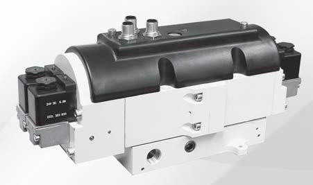
85 CONTROLS SAE CYLINDER STOP & LOAD HOLDING DOULE VALVES CROSSCHECK TM CC SERIES PILOT OPERATED CHECK VALVES SV7, 9, 7 SERIES
86 CROSSCHECK TM CONTROL RELIALE DOULE VALVES, CC SERIES KEY EATURES Closed Center valve function Redundant control with position feedback - can achieve Category, PL e, when used with proper safety controls Designed for external monitoring Mid-position sensing - for detection of safe, closed center position ROSS poppet technology - fast, reliable, dirt-tolerant, face-sealing, low friction LED indicators on solenoids - aids troubleshooting PILOT OPERATED CHECK SENSING VALVES, SV7 SERIES KEY EATURES Poppet construction for near zero leakage & dirt tolerance Direct-operated safety-rated status switch (DPST) Sistema library data available PILOT OPERATED CHECK VALVES, RIGHT-ANGLE, 9 SERIES KEY EATURES Right-angle design for easy positioning of pipe or tubing Inlet ports available with NPT threaded or push-to-connect fittings Galvanized zinc plated brass body construction Lube or non-lube operation PILOT OPERATED CHECK VALVES, 7 SERIES KEY EATURES Available with automatic or manual trapped pressure release when pressure is removed from the lowdown Signal (P) Poppet construction for near zero leakage Applications include Air Holding and Cylinder Load Holding VALVE SERIES Category Air Pilot OPERATION AVAILALE PORT SIZES MAX. LOW (Cv) Solenoid Single Dual Size Integrated Trapped Pressure Relief /8 / /8 / / ¼ ½ /8 / /8 / / ¼ ½ CC Manual SV SV SV SV Optional Remote Remote Manual Remote Manual Solenoid 5.9 Page
 to configure your valve model number.")
87 CROSSCHECK TM Control Reliable Safe Cylinder Stop/Load Holding Double Valves Designed for External Monitoring CC Series / Safety Directional Valve Closed Center HOW TO ORDER (Choose your options (in red) to configure your valve model number.) CC M Coming G A E X S A Series Voltage Revision Level 0 Pressure Release volts DC A Communication None X Pin Configuration Manual M Thread Valve Only X Soon! Standard S Monitoring SPP G Size Inlet Outlet External E NPT N / / 0 Valve Only X /8 /8 / / / / 5 Valve Only (No ase) X CAT, PL e (certification pending) Pilot Valve A Pilot Valve A A Valve Schematic Ext Pi PORT Trapped Pressure Release Valve PORT PORT Trapped Pressure Release Valve PORT Simplified Schematic Size asic C V Inlet Outlet Exhaust Size Weight lb (Kg) / / / (5.) /8 /8 / (5.) / / / (8.) Pilot Valve A Pilot Valve / / / (8.) APPLICATIONS: Category applications - e.g., cylinder stop & load holding applications. The CROSSCHECK TM CC Series valve is designed to be controlled by a safety controller or safety relay with dual channel outputs and the capability of monitoring the mid-position feedback sensors. The valve is a redundant valve and is driven by solenoid pilot valves - two for extending and two for retracting. STANDARD SPECIICATIONS (for valves on this page): Construction: Mounting Type: Sub-base mounted. Pilot Solenoid: Version as per VDE Rated for continuous duty. Enclosure rating according to DIN IP 65. Standard Voltages: volts DC. Pilot Solenoids Power Consumption (each solenoid):.5 watts. Electrical Connections: Three Ambient Temperature: 0 to 0 (+ C to 60 C). Medium Temperature: 0 to 76 (+ C to 80 C). low Media: Compressed, filtered air according to ISO 857-:00 [7::]. Inlet Pressure: With Internal Pilot Supply: 60 to 0 psig ( to 8 bar). With External Pilot Supply: 0 to 0 psig (0 to 8 bar). Pilot Supply Pressure: 60 to 0 psig ( to 8 bar). Must be equal to or greater than inlet pressure. Static Pressure: 0 to 50 psig (0 to 0 bar). Mounting Orientation: preferred. Monitoring: equipment. Monitoring should check state of both valve mid-position sensors with any and all changes in state of valve control signals. unctional Safety Data: Pending. This valve is not designed for controlling clutch/brake mechanisms on mechanical power presses, see DM Series D valves for mechanical power press applications. Rev. 0/0/7 5.
88 CROSSCHECK TM Control Reliable Double Valves Designed for External Monitoring Valve Technical Data CC Series Size / & /8 Valve Dimensions inches (mm) ) Trapped Pressure Release.5 (05.).9 (.) Trapped Pressure Release.0 (0.) 5. (9.7).7 (.). (85.6) ).5 (.5) 6.8 (57.0) External Pilot Supply /. (.).60 (6.7) 0.60 (5.).8 (7.5) 6.0 (57.6).5 (.) Size / & / Trapped Pressure Release 5.60 (.) Trapped Pressure Release.87 (.7).0 (0.5).55 (90.) 6.8 (7.).9 (5.) 5. (.) 0.9 (.0). (0.0) 9.6 (7.7).80 (5.7) 5.80 (7.).0 (5.9) 0.60 (5.) 5.96 (5.) 7.7 (96.) 9. (.8) External Pilot Supply / 5 A 5 5 C Valve Receptacle Pinouts - M Valve Wiring Diagram A & - Solenoids C - Sensor SOL A SOL A - + SOL SOL POWER COMMON SENSOR A SENSOR GROUND A 5 5 C ACCESSORIES & OPTIONS Wiring Kit Description Kit Number M System Cables Cords with female, 5-pin, straight, A-coded connector on one end, flying leads on the opposite end. Number of Cords Cord Length meters (feet) 6K77 5 (6.) 5 Wire Colors rown White lue lack 5 Grey Silencers Dimensions inches (mm) Weight Thread Model Number Avg. Size Type NPT Threads SPT Threads C V A lb (kg) / Male 5500A00 D5500A (). (55) 0. (0.) /8 Male 5500A0 D5500A (). (55) 0. (0.) / Male 5500A00 D5500A00.7. ().6 (9) 0. (0.) / Male 5500A50 D5500A ().6 (9) 0. (0.) Pressure Range: 0 to 00 psig (0 to 0.7 bar) maximum. low Media: iltered air. A 5. 07, ROSS CONTROLS. All Rights Reserved. Rev. 0/0/7
89 CROSSCHECK TM Control Reliable Double Valves Designed for External Monitoring Operation Overview CC Series Conditions at Start: Pressure applied to port, but all solenoids off. All ports (,,, & ) are blocked. A Sensing Midpoint INLET Valve De-energized EXHAUST Normal Operation: Energizing both solenoids A & causes the valve to shift and supply pressure to port while exhausting pressure from port, thus, extending the cylinder. Conversely, energizing solenoids A & causes the valve to shift and supply pressure to port while exhausting pressure from port, thus, causing the cylinder to retract. Turning all the solenoids off allows the strong return springs to shift the redundant valves back to the center position, which blocks all ports. This traps any downstream pressure in the cylinder and holds it in its current position (see below on the right, image of valve de-energized trapping pressure). Each of the mid-position feedback sensors provide a voltage output when the valve is in the center, safe position, but no voltage output when the valve internals are shifted out of the center position. This provides a detectable center position for both sets of valve internals. A Sensor A + VDC Power + VDC 5 Common - 0 VDC Sensor + VDC Ground Abnormal Operation: When energizing, if both sets of valve internals do not shift synchronously (either on or off), the CROSSCHECK TM valve will block all ports. While in this fault condition, the valve cannot further pressurize or exhaust the cylinder lines. Also, as long as the fault condition exists, there will be a voltage output from the valve internals that did not shift from center, but there will not be an output from the other valve internals that did shift off center. This provides a detectable fault condition as both sensors need to agree in order to not indicate a fault. A A Sensing Midpoint Sensing Midpoint INLET INLET Valve aulted Side A, RIght Valve aulted Side A, Left EXHAUST EXHAUST A A Sensor A + VDC Power + VDC 5 Common - 0 VDC Sensor + VDC Ground Sensing Midpoint A A Sensing Midpoint Sensing Midpoint INLET Solenoids A & Energized Presurized INLET Solenoids A & Energized Presurized EXHAUST EXHAUST Monitoring: External monitoring of the CROSSCHECK TM mid-position sensors must be performed by an external monitoring system. Such a monitoring system must be capable of inhibiting the operation of the valve. The safety control system must de-energize the valve s solenoids in the event of a fault within the valve and/or within the safety control system, and check for achievement of the valve center position before allowing an attempt to re-energize the valve. Valve reset is accomplished by de-energizing all of the valve s solenoids. Reset of the safety control system should not occur unless the valve has fully returned to its center position (both sets of internals). The output voltage of the sensors, when switched on (center position), equals approximately the voltage supplied to the sensors by the safety controller. or example, volts DC In = volts DC Out, etc. A A Sensor A 0 VDC Sensor A 0 VDC Power VDC 5 Sensor 0 VDC Ground Common 0 VDC Power VDC 5 Common 0 VDC Sensor 0 VDC Ground A A Sensing Midpoint INLET INLET EXHAUST EXHAUST Trapped Pressure Release: In order to perform machine maintenance, after stopping the machine and performing lockout/tagout, pressure trapped in the cylinder by the CROSSCHECK TM valve can be released (exhausted) by the two manuallyoperated -way valves that are provided in the CROSSCHECK TM valve sub-base - one each per valve outlet port. This provides a way to slowly lower the cylinder to its lowest position. NOTE: Operating the manual trapped pressure release valves will cause movement of the cylinder. Use caution to avoid any hazards associated with this movement. A Sensing Midpoint Valve aulted Side, RIght Valve aulted Side, Left INLET Valve De-energized Trapping Pressure EXHAUST A A A Sensor A + VDC Sensor A + VDC Power + VDC 5 Common - 0 VDC Power + VDC 5 Common - 0 VDC Sensor + VDC Ground Sensor + VDC Ground Rev. 0/0/7 5.5
 / / SV7NC5508CSAA** 8. 5.0 (.) / SV7NC5608CSAA** 0. 5.0 (.) ¼ SV7NC7608CSAA** 0.5 (5.6) ¼ ¼ SV7NC7708CSAA** 9.5 (5.6) ½ ¼ SV7NC7808CSAA**.5 (5.6) /8 EPS /8 PV * NPT port threads.")
90 Single Pilot Operated Check Sensing Valves Designed for External Monitoring Solenoid Pilot Controlled -Way -Position Valves, Closed Size C V ody Size Valve Model Number*, - Weight lb (kg) / / SV7NC508CSAA** (.) / / SV7NC5508CSAA** (.) / SV7NC5608CSAA** (.) ¼ SV7NC7608CSAA** 0.5 (5.6) ¼ ¼ SV7NC7708CSAA** 9.5 (5.6) ½ ¼ SV7NC7808CSAA**.5 (5.6) /8 EPS /8 PV * NPT port threads. or SPP threads, replace N in the model number with a D, e.g., SV7DC508CSAAA. ** Insert voltage code: A =0-0 volts AC, 50/60 Hz; D = volts DC;.e.g., SV7NC508CSAAA. or other voltages, consult ROSS. C V Load Holding SV7 Series ody Size ¼ shown Valve Dimensions inches (mm) ody Size / (CNOMO Style Pilot) ody Size ¼ (Pacer Style Pilot) 8.5 (5) -pin Mini connector (outlet) X O 0.6 (6.7) X- (/8 external pilot supply) 5-pin M connector.8 (99) Y- (pilot exhaust) X O 0.5 (.5) (outlet) -pin Mini connector X- (/8 external pilot supply) 5-pin M connector PV (pressure verification) ACCESSORIES & OPTIONS (inlet) 5.0 (7). (8).8 (99) PV (pressure verification) 5.7 (5) (inlet) Pressure Switches Connection Type EN orm A Preassembled Wiring Kits Model Number* 586A86 Kit Number* Length meters (feet) Number of Cables 9H77 (.) 0H77 0 (.8) * Each cable has one connector. Threads /8 NPT M 5A0 /8 NPT *Pressure switch closes on falling pressure of 5 psig (0. bar). Contact conditions during switch travel (0 to 6 mm). Integrated Double-Pole Single-Throw Switch (DPST) Switch States EN Connector Pinout Open Common Closed Ground Construction: Poppet. Mounting Type: In-Line. Solenoid: AC or DC power. Rated for continuous duty. Standard Voltages: volts DC; 0-0 volts AC, 50/60 Hz. Power Consumption: CNOMO Style: VA inrush, 8.5 VA holding on 50 or 60 Hz; 6 watts on DC. Pacer Style: 87 VA inrush, 0 VA holding on 50 or 60 Hz; watts on DC. Ambient Temperature: 0 to 0 ( to 50 C). Media Temperature: 0 to 75 ( to 80 C). low Media: iltered air. Inlet Pressure: 0 to 50 psig (.8 to 0. bar). Pilot Pressure: Must be equal to or greater than inlet pressure. M Connector Pinout Pin Open Pin Common The wiring kits come with a cord grip on each cable. One cable has a -pin MINI connector for the solenoid and one has a 5-pin M (Micro) connector for the sensing switch. Pin Not Used Pin Closed RN PIN STANDARD SPECIICATIONS (for valves on this page): RN LUE GRN/YEL LUE PIN GRN/YEL (GROUND) PIN Solenoid Cable with -pin MINI Connector Indicator Light Kits for Pacer Style Pilot volts DC 86K87-W LUE LK PIN PIN Kit Number 0-0 volts AC Hz 86K87-Z LUE RN WHT PIN RN PIN GRY PIN 5 Switch Current/Voltage Max.:.5 A/0 volts AC. Switch Current/Voltage Min.: 50 ma/ volts DC. NOTE: Electrical life of switch varies with conditions and voltage; rated in excess of 5 million cycles. unctional Safety Data: Category PL d; 0D: Valve - 0,000,000, Switch,000,000; PHD:.5x0-7 ; MTTD: 98.5 (n op: 760); DC (obtained by monitoring safety switch status): 90%; ROSS recommends testing the switch function and sealing for load holding valves every 8 hours. Vibration/Impact Resistance: Calculated to S EN LK WHT GRN/YEL Current/Voltage Max..5 A /0 VAC Sensing Switch Cable with 5-pin M Connector , ROSS CONTROLS. All Rights Reserved. Rev. 0/0/7
91 Dual Pilot Operated Check Sensing Valves Designed for External Monitoring Solenoid Pilot Controlled Load Holding SV7 Series -Way -Position Redundant Closed Size ody C Valve Model Number* V, Size - Weight lb (kg) / / SV7NC55508CSAA** (.5) / / SV7NC555508CSAA** (.5) / SV7NC555608CSAA** (.5) ¼ SV7NC557608CSAA** 5.0 (.) ¼ ¼ SV7NC557708CSAA** (.) ½ ¼ SV7NC557808CSAA** 5.0 (.) /8 EPS /8 PV C /8 EPS /8 PV V * NPT port threads. or SPP threads, replace N in the model number with a D, e.g., SV7DC55508CSAAA. ** Insert voltage code: A =0-0 volts AC, 50/60 Hz; D = volts DC;.e.g., SV7NC55508CSAAA. or other voltages, consult ROSS. Valve Dimensions inches (mm). (5) ody Size / (CNOMO Style Pilot) -pin Mini connector X Ø 0.6 (6.7) X- (/8 external pilot supply) 5-pin M connector 8. (59) ody Size ¼ (Pacer Style Pilot) Y- (pilot exhaust) (outlet) X Ø 0.5 (.5) -pin Mini connector X- (/8 external pilot supply) 5-pin M connector (inlet) (outlet) -pin Mini connector PV (pressure verification) ACCESSORIES & OPTIONS Pressure Switches Connection Type EN orm A 8. () Preassembled Wiring Kits Model Number* 586A86 (inlet) Kit Number* Length meters (feet) Number of Cables 9H77 (.) 0H77 0 (.8) * Each cable has one connector. Threads /8 NPT M 5A0 /8 NPT *Pressure switch closes on falling pressure of 5 psig (0. bar). Contact conditions during switch travel (0 to 6 mm). Integrated Double-Pole Single-Throw Switch (DPST) Switch States. (8) EN Connector Pinout Open Common Closed Ground.9 (99) M Connector Pinout Pin Open Pin Common The wiring kits come with a cord grip on each cable. One cable has a -pin MINI connector for the solenoid and one has a 5-pin M (Micro) connector for the sensing switch. Pin Not Used Pin Closed RN PIN RN PV (pressure verification) 0.5 (67) LUE GRN/YEL LUE PIN GRN/YEL (GROUND) PIN Solenoid Cable with -pin MINI Connector X- (/8 external pilot supply) -pin Mini connector Indicator Light Kits for Pacer Style Pilot volts DC 86K87-W LUE LK PIN PIN Kit Number 0-0 volts AC Hz 86K87-Z LUE RN LK WHT GRN/YEL Current/Voltage Max..5 A /0 VAC WHT PIN RN PIN GRY PIN 5 Sensing Switch Cable with 5-pin M Connector Construction: Poppet. Mounting Type: In-Line. Solenoid: AC or DC power. Rated for continuous duty. Standard Voltages: volts DC; 0-0 volts AC, 50/60 Hz. Power Consumption: CNOMO Style: VA inrush, 8.5 VA holding on 50 or 60 Hz; 6 watts on DC. Pacer Style: 87 VA inrush, 0 VA holding on 50 or 60 Hz; watts on DC. Ambient Temperature: 0 to 0 ( to 50 C). Media Temperature: 0 to 75 ( to 80 C). low Media: iltered air. Inlet Pressure: 0 to 50 psig (.8 to 0. bar). Pilot Pressure: Must be equal to or greater than inlet pressure. STANDARD SPECIICATIONS (for valves on this page): Switch Current/Voltage Max.:.5 A/0 volts AC. Switch Current/Voltage Min.: 50 ma/ volts DC. NOTE: Electrical life of switch varies with conditions and voltage; rated in excess of 5 million cycles. unctional Safety Data: Category PL e; 0D: Valve - 0,000,000, Switch,000,000; PHD:.7x0-8 ; MTTD: 00 (n op: 760); DC (obtained by monitoring safety switch status): 90%; ROSS recommends testing the switch function and sealing for load holding valves every 8 hours. Vibration/Impact Resistance: Calculated to S EN Rev. 0/0/7 5.7
 / / SV7NC5505ASAA 8..0 (.8) / SV7NC5605ASAA 0..0 (.8) ¼ SV7NC7605ASAA 0.0 (5.0) ¼ ¼ SV7NC7705ASAA 9.0 (5.0) ½ ¼ SV7NC7805ASAA.0 (5.0) / Signal port /8 PV C V * NPT port threads.")
92 Single Pilot Operated Check Sensing Valves Designed for External Monitoring Pressure Controlled Load Holding SV7 Series -Way -Position Valves Size ody Valve Model C V, Size Number* - Weight lb (kg) / / SV7NC505ASAA.5.0 (.8) / / SV7NC5505ASAA 8..0 (.8) / SV7NC5605ASAA 0..0 (.8) ¼ SV7NC7605ASAA 0.0 (5.0) ¼ ¼ SV7NC7705ASAA 9.0 (5.0) ½ ¼ SV7NC7805ASAA.0 (5.0) / Signal port /8 PV C V * NPT port threads. or SPP threads, replace N in the model number with a D, e.g., SV7DC505ASAA. Valve Dimensions inches (mm) 6. (5) / Signal port PV (pressure X Ø / Signal port verification) 0.6 (6.7) (outlet) ody Size / 5.0 (7) ACCESSORIES & OPTIONS 5-pin M connector (inlet). (8) 8.6 (8) / Signal port PV / Signal port (pressure verification) X Ø 0.5 (.5).8 (99) (outlet) ody Size ¼ 5.7 (5) 5-pin M connector (inlet) Pressure Switches Connection Type Model Number* Threads EN orm A 586A86 /8 NPT M 5A0 /8 NPT *Pressure switch closes on falling pressure of 5 psig (0. bar). Preassembled Wiring Kits Kit Number* Length meters (feet) Number of Cables H77 (.) H77 0 (.8) * Each cable has one connector. Integrated Double-Pole Single-Throw Switch (DPST) Switch States Contact conditions during switch travel (0 to 6 mm). EN Connector Pinout Open Common Closed Ground M Connector Pinout Pin Open Pin Common Pin Not Used Pin Closed The wiring kits include one cable with a 5-pin M connector for the sensing switch, and a cord grip. Sensing Switch Cable with 5-pin M Connector LUE LK PIN PIN LUE RN LK WHT GRN/YEL Current/Voltage Max..5 A /0 VAC WHT PIN RN PIN GRY PIN 5 STANDARD SPECIICATIONS (for valves on this page): Construction: Poppet. Mounting Type: In-Line. Ambient Temperature: 0 to 0 ( to 50 C). Media Temperature: 0 to 75 ( to 80 C). low Media: iltered air. Inlet Pressure: 0 to 50 psig (.8 to 0. bar). Pilot Pressure: Must be equal to or greater than inlet pressure. Switch Current/Voltage Max.:.5 A/0 volts AC. Switch Current/Voltage Min.: 50 ma/ volts DC. NOTE: Electrical life of switch varies with conditions and voltage; rated in excess of 5 million cycles. unctional Safety Data: Category PL d; 0D: Valve - 0,000,000, Switch,000,000; PHD:.5x0-7 ; MTTD: 98.5 (n op: 760); DC (obtained by monitoring safety switch status): 90%; ROSS recommends testing the switch function and sealing for load holding valves every 8 hours. Vibration/Impact Resistance: Calculated to S EN , ROSS CONTROLS. All Rights Reserved. Rev. 0/0/7
 / / SV7NC555505ASAA 5.6 9.0 (.) / SV7NC555605ASAA 8 9.0 (.) ¼ SV7NC557605ASAA.0 (0.0) ¼ ¼ SV7NC557705ASAA 9.0 (0.0) ½ ¼ SV7NC557805ASAA.0 (0.0) / Signal port / Signal port /8 PV /8 PV C V * NPT port threads.")
93 Dual Pilot Operated Check Sensing Valves Designed for External Monitoring Pressure Controlled Load Holding SV7 Series -Way -Position Valves Size ody Valve Model C V, Size Number* - Weight lb (kg) / / SV7NC55505ASAA (.) / / SV7NC555505ASAA (.) / SV7NC555605ASAA (.) ¼ SV7NC557605ASAA.0 (0.0) ¼ ¼ SV7NC557705ASAA 9.0 (0.0) ½ ¼ SV7NC557805ASAA.0 (0.0) / Signal port / Signal port /8 PV /8 PV C V * NPT port threads. or SPP threads, replace N in the model number with a D, e.g., SV7DC55505ASAA. Valve Dimensions inches (mm) ody Size / / Signal port / Signal port X Ø 0.6 (6.7) 5-pin M connector / Signal port (outlet) X Ø 0.5 (.5) ody Size ¼ 5-pin M connector / Signal port 8.5 ().7 (96) (inlet) (outlet) PV (pressure verification) 8. () ACCESSORIES & OPTIONS (inlet). (8).5 (88) 0.5 (67) PV (pressure verification) Pressure Switches Connection Type Model Number* Threads EN orm A 586A86 /8 NPT M 5A0 /8 NPT *Pressure switch closes on falling pressure of 5 psig (0. bar). EN Connector Pinout Open Common Closed Ground M Connector Pinout Pin Open Pin Common Pin Not Used Pin Closed Preassembled Wiring Kits SV7 Redundant PO Check valves (CAT ), requires kits. Kit Number* Length meters (feet) Number of Cables H77 (.) H77 0 (.8) * Each cable has one connector. Contact conditions during switch travel (0 to 6 mm). Integrated Double-Pole Single-Throw Switch (DPST) Switch States The wiring kits include one cable with a 5-pin M connector for the sensing switch, and with a cord grip. Sensing Switch Cable with 5-pin M Connector LUE LK PIN PIN LUE RN LK WHT GRN/YEL Current/Voltage Max..5 A /0 VAC WHT PIN RN PIN GRY PIN 5 STANDARD SPECIICATIONS (for valves on this page): Construction: Poppet. Mounting Type: In-Line. Ambient Temperature: 0 to 0 ( to 50 C). Media Temperature: 0 to 75 ( to 80 C). low Media: iltered air. Inlet Pressure: 0 to 50 psig (.8 to 0. bar). Pilot Pressure: Must be equal to or greater than inlet pressure. Switch Current/Voltage Max.:.5 A/0 volts AC. Switch Current/Voltage Min.: 50 ma/ volts DC. NOTE: Electrical life of switch varies with conditions and voltage; rated in excess of 5 million cycles. unctional Safety Data: Category PL e; 0D: Valve - 0,000,000, Switch,000,000; PHD:.7x0-8 ; MTTD: 00 (n op: 760); DC (obtained by monitoring safety switch status): 90%; ROSS recommends testing the switch function and sealing for load holding valves every 8 hours. Vibration/Impact Resistance: Calculated to S EN Rev. 0/0/7 5.9
 /8 /8 958A00 0- UN 0. 0.. (0) / / 958A00 0- UN 0.8 0.7.75 (0) /8 /8 958A00 0- UN... (0) / / 958A00 0- UN.. 9.50 (0) G/8 G/ D958A00* M5 0. 0. 7.8 (0) G/ G/ D958A00* M5 0.8 0.7 8.")
 Pilot Signal Size /.")
94 Pilot Operated Check Valves Right-Angle with Threaded anjo Cylinder Position Holding 9 Series Size (female threads) (male threads) Models with Threaded anjo Valve Model Number C V - - Tightening Torque Max. t-lb (Nm) /8 /8 958A00 0- UN (0) / / 958A00 0- UN (0) /8 /8 958A00 0- UN... (0) / / 958A00 0- UN (0) G/8 G/ D958A00* M (0) G/ G/ D958A00* M () G/8 G/8 D958A00* M (0) G/ G/ D958A00* M5... (0) * SPP port threads. Valve Dimensions inches (mm).7 ().9 (8) Size /8 0.5 () Size / 0.7 (7) Pilot Signal Pilot Signal. (55).6 (66) Size /8 0.9 () Pilot Signal Size /. (7) Pilot Signal Signal Pressure: The charts below show the minimum signal pilot port pressure to open the valve versus port pressure (P ) when there is no pressure at port (P = 0 bar). (bar) (bar) (bar) (bar) P (bar) G/8 - /8 NPT P (bar) G/ - / NPT P (bar) G/8 - /8 NPT P (bar) G/ - / NPT ACCESSORIES & OPTIONS Manual Override Manual Trapped Pressure Relief Adapter Threads Model Number* 5/ 0- Manual Operated Check NPT 998A05 M5 M5 Manual Operated Check SPP D998A00 * Adapter threads into the signal port. Construction: Poppet. Mounting Type: In-Line. Ambient/Media Temperature: 5 to 60 (-0 to 70 C). STANDARD SPECIICATIONS (for valves on this page): Valve Illustrated with Optional Manual Trapped Pressure Relief Adapter low Media: iltered air. Operating Pressure: 5 to 50 psig ( to 0 bar) , ROSS CONTROLS. All Rights Reserved. Rev. 0/0/7
 5/ /8 958A5 0- UN 0. 0..06 (5) / /8 958A0 0- UN 0. 0..06 (5) / / 958A0 0- UN 0.8 0.7.75 (0) /8 / 958A0 0- UN 0.8 0.7.75 (0) /8 /8 958A0 0- UN.")
95 Pilot Operated Check Valve Right-Angle with Push-to-Connect itting Cylinder Position Holding 9 Series # (tube fittings) Size (male threads) Models with Push-to-Connect itting Valve Model Number C V - - Tightening Torque Max. t-lb (Nm) 5/ /8 958A5 0- UN (5) / /8 958A0 0- UN (5) / / 958A0 0- UN (0) /8 / 958A0 0- UN (0) /8 /8 958A0 0- UN... (0) mm G/8 D958A0* M (0) 6 mm G/8 D958A60* M (0) 8 mm G/8 D958A80* M (0) 6 mm G/ D958A60* M ( 8 mm G/ D958A80* M () 0 mm G/ D958A0* M () 8 mm G/8 D958A80* M (0) 0 mm G/8 D958A0* M (0 # tubing size in inches ( ) or millimeters (mm). * SPP port threads. Valve Dimensions inches (mm).7 ().9 (8). (55) Size /8 () Size / (7) Size /8 Pilot Signal Pilot Signal 0.9 () Pilot Signal Signal Pressure: The charts below show the minimum signal pilot port pressure to open the valve versus port pressure (P ) when there is no pressure at port (P = 0 bar). (bar) (bar) (bar) (bar) P (bar) G/8 - /8 NPT P (bar) G/ - / NPT P (bar) G/8 - /8 NPT P (bar) G/ - / NPT OPTIONS Manual Override Manual Trapped Pressure Relief Adapter Threads Model Number* 5/ 0- Manual Operated Check NPT 998A05 M5 M5 Manual Operated Check SPP D998A00 * Adapter threads into the signal port. STANDARD SPECIICATIONS (for valves on this page): Valve Illustrated with Optional Manual Trapped Pressure Relief Adapter Construction: Poppet. Mounting Type: In-Line. Ambient/Media Temperature: 5 to 60 (-0 to 70 C). low Media: iltered air. Operating Pressure: 5 to 50 psig ( to 0. bar). Rev. 0/0/7 5.
 / 75A95 /8-7 NPT.. (.0) * NPT port threads. or SPP threads, add a D prefix to the model number, e.g.,d75a908. Valve Dimensions inches (mm) Size / /8-7 NPT SIGNAL PORT /-8 NPT (X).7 (.")
96 Single Pilot Operated Check Valves without Trapped Pressure Relief Load Holding 7 Series -Way -Position, Pressure Controlled s Size Valve Model Number* Signal C V Weight lb (kg) / 75A908 /8-7 NPT.. (.0) /8 75A908 /8-7 NPT.9. (.0) / 75A95 /8-7 NPT.. (.0) * NPT port threads. or SPP threads, add a D prefix to the model number, e.g.,d75a908. Valve Dimensions inches (mm) Size / /8-7 NPT SIGNAL PORT /-8 NPT (X).7 (.6).7 (.) /8-7 NPT SIGNAL (X) PORT /-8 NPT (X).7 (.6).5 (8.5).67 (9.7) 0.8 (.) 0. (.).6 (.) 0.5 (9.0).5 (8.) 0.75 (9.).6 (.).99 (50.) 0.7 (9.) 0.75 (9.) (X) Size /8 /8-7 NPT SIGNAL PORT /8-8 NPT (X).7 (.6). (0.) /8-7 NPSM SIGNAL PORT /8-8 (X).7 (.6) (X).5 (8.5) NPT.69 (9.7) 0.77 (9.56) 0. (.).6 (.) 0.5 (9.0).5 (8 ) 0.75 (9.).6 (.) 0.7 (9.) 0.75 (9.) (X) Size / /8-7 NPT SIGNAL PORT /- NPT.75 (.5) 0. (8.5).8 (.5).5 (85.6).79 (96.) /- NPT /8-7 NPT SIGNAL PORT 0.5 (.).8 (7.6) 0.9 (.5).5 (8.) 0.75 (9.).8 (7.6).7 (6.5) 0.50 (.7) 0.75 (9.) (X) Cylinder Single Pilot Operated Check Valve Application CIRCUIT EATURES: Cylinder moves as long as the control valve solenoid is energized. Use for continuous motion or jogging. Cylinder remains stationary if neither control valve solenoid is energized, or if electrical signal is lost. Check Valve with Internal Pilot CYL VALVE low Control Valves VALVE CYL Check Valve with Internal Pilot L-O-X Valve (Lockout & Exhaust) - Position, Open-Center Control Valve Construction: Poppet. Mounting Type: In-Line. Ambient/Media Temperature: 0 to 75 ( to 80 C). STANDARD SPECIICATIONS (for valves on this page): Inlet Pressure: 5 to 50 psig ( to 0. bar). low Media: iltered air. Signal Pressure: Must be equal to or greater than inlet pressure , ROSS CONTROLS. All Rights Reserved. Rev. 0/0/7
 /8 /8 75A90 /.8. (0.6) / /8 75A90 /. (0.6) / / 75A905 / 7.7. (.0) / / 75A590 / 9. (.0) / 75A690 / 9. (.0) ¼ 75690 / 6.0 (.7) ¼ ¼ 75790 / 9 6.0 (.7) ½ ¼ 75890 / 9 6.0 (.7) * NPT port threads.")
97 Single Pilot Operated Check Valves without Trapped Pressure Relief Load Holding 7 Series -Way -Position, Pressure Controlled s Size ody Size Valve Model Number* Signal C V Weight lb (kg) / /8 75A90 /.. (0.6) /8 /8 75A90 /.8. (0.6) / /8 75A90 /. (0.6) / / 75A905 / 7.7. (.0) / / 75A590 / 9. (.0) / 75A690 / 9. (.0) ¼ / 6.0 (.7) ¼ ¼ / (.7) ½ ¼ / (.7) * NPT port threads. or SPP threads, add a D prefix to the model number, e.g.,d75a90. Valve Dimensions inches (mm) ody Size /8 0. (8).7 (9).5 (55) / Signal port.8 (7).7 (88) 0. (8) 0.8 (0) (inlet) { (outlet) on opposite side}.6 (7).5 (80).5 (9) ody Size / ody Size ½ 0. (8). ().7 (70) / Signal port.5 (8).5 () 0. (8) 0.66 (7) (inlet) { (outlet) on opposite side}.80 (6).5 (9).5 (80) 7.9 (90).50 () 0.5 () / Signal port.65 (8) 6.9 (65) 0.8 () 0.5 () (inlet) { (outlet) on opposite side}.09 (78).78 (5).09 (0) Cylinder Single Pilot Operated Check Valve Application CIRCUIT EATURES: Cylinder moves as long as the control valve solenoid is energized. Use for continuous motion or jogging. Cylinder remains stationary if neither control valve solenoid is energized, or if electrical signal is lost. Check Valve with Internal Pilot C low Control Valves V V C Check Valve with Internal Pilot L-O-X Valve (Lockout & Exhaust) - Position, Open-Center Control Valve STANDARD SPECIICATIONS (for valves on this page): Construction: Poppet. Mounting Type: In-Line. Ambient/Media Temperature: 0 to 75 ( to 80 C). Inlet Pressure: 5 to 50 psig ( to 0. bar). low Media: iltered air. Signal Pressure: Must be equal to or greater than inlet pressure. Rev. 0/0/7 5.
 / 75A9 /8-7 NPT.8.8 (0.8) / 75A597 /8-7 NPT 9..9 (.) VP VLV CYL P * NPT port threads. or SPP threads, add a D prefix to the model number, e.g.,d75a9. Valve Dimensions inches (mm) Size /8 0.")
98 Single Pilot Operated Check Valves with Remote Trapped Pressure Relief Load Holding 7 Series -Way -Position, Pressure Controlled s Size Valve Model Number* Signal C V Weight lb (kg) /8 75A9 /8-7 NPT.6.8 (0.8) / 75A9 /8-7 NPT.8.8 (0.8) / 75A597 /8-7 NPT 9..9 (.) VP VLV CYL P * NPT port threads. or SPP threads, add a D prefix to the model number, e.g.,d75a9. Valve Dimensions inches (mm) Size / (.) /8-8 NPT.5 (9.) 0. (.). (.0) /-8 NPT Pilot (8.) (0.).65 (.9).5 (.8) 0.8 (.0) (X) /8-7 NPT Exhaust.90 (99.).0 (77.) /8-8 NPT 0.65 (6.5).7 (88.) 0.8 (.0) Size / (X) /-8 NPT Pilot.5 (8.) (.) /- NPT 0. (.) 0.0 (0.).5 (.8) 0.8 (.0).65 (.9).90 (99.).0 (77.).7 (88.) /- NPT 0.65 (6.5) 0.8 (.0) /- NPT.5 (89.9).- NPT Size / (X) /-8 NPT Pilot. (5.0).50 (8.) 0. (.) 0. (0.).8 (7.5).0 (8.0).0 (55.9).0 (09.).7 (05.9) 0.75 (9.).0 (8.0) Single Pilot Operated Check Valve with Trapped Pressure Relief Application CIRCUIT EATURES: Trapped pressure between check valve and cylinder is exhausted when the air supply at the lowdown Signal (P) is lost or locked-out. Cylinder moves as long as the control valve solenoid is energized. Use for continuous motion or jogging. Cylinder remains stationary if neither control valve solenoid is energized, or if electrical signal is lost. 0 L-O-X Valve (Lockout & Exhaust) 5 VLV -Position, Open-Center Control Valve P Single PO Check Valve VP CYL Vertical Cylinder STANDARD SPECIICATIONS (for valves on this page): Construction: Poppet. Mounting Type: In-Line. Ambient/Media Temperature: 0 to 75 ( to 80 C). Inlet Pressure: 5 to 50 psig ( to 0. bar). low Media: iltered air. Signal Pressure: Must be equal to or greater than inlet pressure , ROSS CONTROLS. All Rights Reserved. Rev. 0/0/7
 / 75A90.8.8 (0.8) / 75A599 9..9 (.) VLV P CYL * NPT port threads. or SPP threads, add a D prefix to the model number, e.g.,d75a90. Valve Dimensions inches (mm) Size /8 /8-8 NPT 0.88 (.).5 (.8) 0.(.).0 (77.")
99 Single Pilot Operated Check Valves with Manual Trapped Pressure Relief Load Holding 7 Series -Way -Position, Pressure Controlled s Size Valve Model Number* C V Weight lb (kg) VP /8 75A (0.8) / 75A (0.8) / 75A (.) VLV P CYL * NPT port threads. or SPP threads, add a D prefix to the model number, e.g.,d75a90. Valve Dimensions inches (mm) Size /8 /8-8 NPT 0.88 (.).5 (.8) 0.(.).0 (77.) /8-8 NPT 0.65 (6.5).7 (88.) /-8 NPT Pilot.5 (8.) 0.0 (0.) 0.8 (.0).65 (.9).90 (99.) 0.8 (.0) Size / /- NPT (.).5 (.8) /- NPT.7 (88.) (77.) (6.5) (X) /-8 NPT Pilot.5 (8.) 0. (.) 0.0 (0.) 0.8 (.0).65 (.9).90 (99.) 0.8 (.0) Size / /- NPT.50 (8.).8 (7.5).5 (89.9).7 (05.9).- NPT (/-8 NPT Pilot. (5.0) 0.0 (0.) 0. (0.).0 (8.0).0 (55.9).0 (09.) 0.75 (9.).0 (8.0) Single Pilot Operated Check Valve with Manual Trapped Pressure Relief Application CIRCUIT EATURES: Trapped pressure between check valve and cylinder is exhausted when the manual relief button is pressed. Cylinder moves as long as the control valve solenoid is energized. Use for continuous motion or jogging. Cylinder remains stationary if neither control valve solenoid is energized, or if electrical signal is lost. 5 0 L-O-X Valve (Lockout & Exhaust) -Position, Open-Center Control Valve Single PO Check Valve VP VLV P CYL Vertical Cylinder STANDARD SPECIICATIONS (for valves on this page): Construction: Poppet. Mounting Type: In-Line. Ambient/Media Temperature: 0 to 75 ( to 80 C). Inlet Pressure: 5 to 50 psig ( to 0. bar). low Media: iltered air. Signal Pressure: Must be equal to or greater than inlet pressure. Rev. 0/0/7 5.5
100 Dual Pilot Operated Check Valves without Trapped Pressure Relief Load Holding 7 Series -Way -Position, Pressure Controlled s Size Valve Model Number* Signal C V Weight lb (kg) /8 768C900 /8-7 NPT.9.0 (0.9) / 768C900 /8-7 NPT.. (.) C / 768C5900 /8-7 NPT 8.5 #.8 (.7) V V 768A6900 /8-7 NPT 8.5 # 6.8 (.) * NPT port threads. or SPP threads, add a D prefix to the model number, e.g.,d768c900. # Effective C V varies with load and pressure drop. Consult ROSS for specifics on your system. C Valve Dimensions inches (mm) Size /8. (.) (X) /8-8 NPT.0 (5.9) 0.60 (5.). (.) (X) /8-8 NPT.0 (.) 0.6 (9.).5 (8.) (60.5) (6.) (5.) (6.6).8 (85.9) 0.95 (.0).67 (67.7). (78.9) Size /. (X) /- NPT (.).0 (5.9). (8.). (.) 0.90 (.9) (X) /- NPT (X).90 (8.).5 (8.) (60.5) (6.) (5.) (6.6).8 (85.9). (8.6) Size / (X) /- NPT (X).65 (.7).95 (00.) 0. (5.5).75 (.5) (X).5 (8.7) (X) /- NPT. (79.7).77 (95.7).68 (.6).5 (.) 0. (8.6).75 (.5) 0.8 (.).00 (76.) 0.7 (7.9).5 (9.).08 (5.8).8 (.) Size (X).78 (70.6).7 (0.).9 (9.).9 (8.9) 0.5 (.).75 (X) (.5).8 (6.) 0. (8.6).75.5 (.5) (9.).8 (97.6) (X) -.5 NPT (X) 0.87 (.0).9 (8.8).9 (9.) 5.78 (6.8).6 (85.).88 (98.6) Cylinder low Control Valves Dual Pilot Operated Check Valve Application CIRCUIT EATURES: Cylinder moves as long as the control valve solenoid is energized. Use for continuous motion or jogging. Cylinder remains stationary if neither control valve solenoid is energized, or if electrical signal is lost. C V V C Dual Check Valve with Internal Pilot L-O-X Valve (Lockout & Exhaust) Construction: Poppet. Mounting Type: In-Line. Ambient/Media Temperature: 0 to 75 ( to 80 C). STANDARD SPECIICATIONS (for valves on this page): - Position, Open- Center Control Valve Inlet Pressure: 5 to 50 psig ( to 0. bar). low Media: iltered air. Signal Pressure: Must be equal to or greater than inlet pressure. Optional Safety Exhaust Valve , ROSS CONTROLS. All Rights Reserved. Rev. 0/0/7
 / 768D90 /8-7 NPT.. (.) / 768D590 /8-7 NPT 8.5 #.8 (.7) 768D690 /8-7 NPT 8.5 # 7. (.) * NPT port threads. or SPP threads, add a D prefix to the model number, e.g.,d768d90.")
101 Dual Pilot Operated Check Valves with Remote Trapped Pressure Relief Load Holding 7 Series -Way -Position, Pressure Controlled s Size Valve Model Number* Signal C V Weight lb (kg) /8 768D90 /8-7 NPT.9. (.) / 768D90 /8-7 NPT.. (.) / 768D590 /8-7 NPT 8.5 #.8 (.7) 768D690 /8-7 NPT 8.5 # 7. (.) * NPT port threads. or SPP threads, add a D prefix to the model number, e.g.,d768d90. # Effective C V varies with load and pressure drop. Consult ROSS for specifics on your system. C V V C Valve Dimensions inches (mm) Size /8. (6.6) 0.9 (.) /8-7 NPT SIGNAL PORT (X) /8-8 NPT 0.59 (5.0).98 (50.).8 (60.5) 0.85 (.6) (X) /8-8 NPT.7 (.8) 0.7 (9.0) (5.) (5.) (6.6) (.0).8 (85.9). (8.).68 (9.) Size / /8-7 NPT SIGNAL PORT (X) /- NPT 0.85 (.6) (X) /- NPT.9 (5.). (8.).68 (9.). (6.6) (5.0) (.).98 (50.).8 (60.5) 0.7 (9.0) 0.0 (5.).00 (5.). (6.6) 0.95 (.0).8 (85.9) Size / /8-7 NPT SIGNAL PORT.98 (0.).09 (5.9). (9.7) 0.0 (5.) (X) /- NPT (X).8 (7.6) 0.7 (8.).50 (8.) 0.9 (9.9).5 (6.0) (7.) (5.) (X) /- NPT.6 (0.7).5 (.).68 (.6).8 (.).7 (9.9).7 (0.9) Size /8-7 NPT SIGNAL PORT (X) -.5 NPT.8 (06.).9 (9.).9 (9.0) 0.80 (0.) (X).68 (68.0) 0.8 (0.8).00 (76.).8 (97.6).75 (.5).7 (.5) 0.5(8.8) 0.50 (.7) (X) -.5 NPT.9 (9.0).9 (9.) 5.78 (6.8).7 (9.9).7 (0.9) Cylinder Dual Pilot Operated Check Valve Remote Trapped Pressure Relief Application CIRCUIT EATURES: Trapped pressure between check valve and cylinder is exhausted when the air supply at the port P is lost or locked-out. Cylinder moves as long as the control valve solenoid is energized. Use for continuous motion or jogging. Cylinder remains stationary if neither control valve solenoid is energized, or if electrical signal is lost. C - Position, Open-Center Control Valve low Control Valves V V Remote-controlled Check Valve Relief Dual Check Valve with Internal Pilot C Holding Pressure P Optional Safety Exhaust Valve L-O-X Valve (Lockout & Exhaust) Construction: Poppet. Mounting Type: In-Line. Ambient/Media Temperature: 0 to 75 ( to 80 C). STANDARD SPECIICATIONS (for valves on this page): Inlet Pressure: 5 to 50 psig ( to 0. bar). low Media: iltered air. Signal Pressure: Must be equal to or greater than inlet pressure. Rev. 0/0/7 5.7
 / 768D590 8.5 #.8 (.7) V V 768D690 8.5 # 6.58 (.0) * NPT port threads. or SPP threads, add a D prefix to the model number, e.g.,d768d90. # Effective C V varies with load and pressure drop.")
102 Dual Pilot Operated Check Valves with Manual Trapped Pressure Relief Load Holding 7 Series -Way -Position, Pressure Controlled s Size Valve Model Number C V Weight lb (kg) /8 768D90.9. (.) C A C / 768D90.. (.) / 768D #.8 (.7) V V 768D # 6.58 (.0) * NPT port threads. or SPP threads, add a D prefix to the model number, e.g.,d768d90. # Effective C V varies with load and pressure drop. Consult ROSS for specifics on your system. Valve Dimensions inches (mm) Size /8 Manual Push-utton Pressure Relief (X). /8-8 NPT (6.6) 0.9 (.) 0.59 (5.0).98 (50.).8 (60.5) 0.85 (.6) 0.7 (9.0) 0.0 (5.) (X) /8-8 NPT. (.) (5.) (6.6) (.0).8 (85.9).8 (7.0). (8.) Size / Manual Push-utton Pressure Relief. (6.6) (X) /- NPT 0.59 (5.0) 0.9 (.).98 (50.).8 (60.5) 0.85 (.6) 0.7 (9.0) 0.0 (5.) (X) /- NPT.9 (5.).00 (5.). (6.6).8 (85.9).8 (7.0).8 (8.) Size / (X) /- NPT.0 (0.5) (X) /- NPT.6 (0.8). (8.8).97 (00.8) 0.9 (9.9) Manual Push-utton Pressure Relief.09 (5.9) (8.) (9.).5 (6.0).9 (7.) 0.0 (5.).5 (.7).68 (.6).8 (.) Size.8 (06.) 0.80 (0.) (X).68 (67.9).75 (.) (X) -.5 NPT.7 (.). (8.7).96 (00.7) (X) -.5 NPT Manual Push-utton Pressure Relief.9 (9.).9 (9.0) 0.8 (0.7).00 (76.).8 (97.6) 0.5 (8.7).9 (9.0).9 (9.) 5.78 (6.8) Cylinder low Control Valves Manual-controlled Check Valve Relief Dual Pilot Operated Check Valve Manual Trapped Pressure Relief Application CIRCUIT EATURES: Trapped pressure between check valve and cylinder is exhausted when push buttons A and are pressed. Cylinder moves as long as the control valve solenoid is energized. Use for continuous motion or jogging. Cylinder remains stationary if neither control valve solenoid is energized, or if electrical signal is lost. C A - Position, Open-Center Control Valve V V C Dual Check Valve with Internal Pilot Optional Safety Exhaust Valve L-O-X Valve (Lockout & Exhaust) Construction: Poppet. Mounting Type: In-Line. Ambient/Media Temperature: 0 to 75 ( to 80 C). STANDARD SPECIICATIONS (for valves on this page): Inlet Pressure: 5 to 50 psig ( to 0. bar). low Media: iltered air. Signal Pressure: Must be equal to or greater than inlet pressure , ROSS CONTROLS. All Rights Reserved. Rev. 0/0/7
103 Dual Pilot Operated Check Valves with Remote Trapped Pressure Relief Solenoid Pilot Controlled Load Holding 7 Series s Size DIN Connector -Way -Position, Solenoid Pilot Controlled Valve Model Number* -Pin Mini Connector Volts DC -Pin Mini Volts DC -Pin Micro /8 778D900** 778D90** 778D90 778D90 /8-7 NPT.9 C C / 778D900** 778D90** 778D90 778D90 /8-7 NPT. / 778D5900** 778D590** 778D D590 /8-7 NPT 8.5 # V V 778D6900** 778D690** 778D D690 /8-7 NPT 8.5 # * NPT port threads. or SPP threads, add a D prefix to the model number, e.g.,d778d900w. **Insert voltage code: W = volts DC; Z = 0-0 volts AC, 50/60 Hz; e.g.,d778d900w. or other voltages, consult ROSS. # Effective C V varies with load and pressure drop. Consult ROSS for specifics on your system. Signal C V Sol C Valve Dimensions inches (mm) Size /8 Size / (X) /8-8 NPT (X).7 (.8) 0.85 (.6). (0.99) (X) /8-8 NPT 0.59 (5.0) /8-7 NPT SIGNALPORT (9.0) (8.).68 (9.) (X) /- NPT (X).9 (5.) 0.85 (.6). (.0) (X) /- NPT 0.59 (5.0) /8-7 NPT SIGNAL PORT (8.) (9.0).68 (9.). (6.6) 0.95 (.0).8 (60.5).98 (50.).00 (5.). (6.6).8 (85.9). (6.6) 0.95 (.0).98 (50.).8 (60.5).00 (5.). (6.6).8 (85.9).98 (0.).09 (5.9) /8-7 NPT SIgnal.8 (06.). (9.7) 0.0 (5.) /8-7 NPT SIGNAL PORT (X) /- NPT (X).8 (7.6) 0.7 (8.) 0.80 (0.).5 (6.0) (7.) (5.) Size /.50 (8.) 0.9 (9.9) (X) /- NPT.6 (0.7).5 (.) Size (X) -.5 NPT.68 (.6).8 (.).7 (9.9) 5.77 (6.5).7 (0.9).7 (9.9) Dual Pilot Operated Check Valve Solenoid Pilot Controlled Application CIRCUIT EATURES: To operate cylinder, simultaneously energize solenoids A and C or and C. Pilot supply and exhaust are independent of control valve. Response time is not affected by exhaust restrictions of the control valve. Cylinder remains stationary if neither control valve solenoid is energized, or if electrical signal is lost. Pressure in cylinder is exhausted when the air supply at P port is lost or locked-out. L-O-X valve provides lockable shut-off of air supply, and exhausting of trapped downstream air. (X) -.5 NPT.9 (9.).9 (9.0) (X).68 (67.9) 0.8 (0.7).00 (76.).8 (97.6).75 (.).7 (.) 0.5 (8.7).9 (9.0) Connector Wiring.9 (9.) 5.78 (5.8) 5.77 (6.5).7 (0.9) C Sol A low Control Valves V Sol C V Sol Cylinder Remote-controlled Check Valve Relief Dual Check Valve with Solenoid Pilot and Relief unction C Holding Pressure P L-O-X Valve (Lockout & Exhaust) SOLENOID DIN Connector SOLENOID DC Mini Connector AC Mini Connector Common SOLENOID + VDC Construction: Poppet. Mounting Type: In-Line. Solenoids: AC or DC power. Standard Voltages: volts DC; 0-0 volts AC, 50/60 Hz. Power Consumption: 8 VA inrush, 6 VA holding on AC; on DC.5 watts with -pin Micro connector, 60 watts with -pin connector. DC Micro Connector STANDARD SPECIICATIONS (for valves on this page): - Position, Open-Center Control Valve Optional Safety Exhaust Valve Ambient Temperature: 0 to 0 ( to 50 C). Media Temperature: 0 to 75 ( to 80 C). Inlet Pressure: 0 to 50 psig ( to 0 bar). Pilot Pressure: Must be equal to or greater than inlet pressure. + VDC SOLENOID Common Rev. 0/0/7 5.9
104

")


105 CONTROLS SAETY EXHAUST (DUMP) EXPLOSION-PROO VALVES DM SERIES C, 7 & SERIES
106 POPPET 7 & SERIES EXPLOSION PROO VALVES KEY EATURES 7 Series - Construction - Acetal internals Series - Construction - Metal, Aluminum Poppet construction for near zero leakage and high dirt tolerance Pilot can rotate, giving the ability to change orientation Self-cleaning Wear compensating Repeatability throughout the life of the valve DESCRIPTION AVAILALE INLET PORT SIZES UNCTIONS Explosion Proof Certifications VALVE TYPE/ SERIES Spool & Sleeve Poppet /8 / /8 / / ¼ ½ ½ / / / / 5/ Single 5/ Double Max low (Cv) Solenoid Control Closed Open CSA/UL ATEX # Page 7 SERIES Poppet Valves SERIES for Low Temperature Accessories CONTROL RELIALE DOULE VALVES DM SERIES KEY EATURES Rapid response time to minimize stopping time Status Indicator switch for valve condition (ready-to-run) feedback Highly contaminant tolerant poppet construction VALVE TYPE/ SERIES Category Available Sizes MAX. LOW Cv Reset / /8 / / ½ Size Integrated Soft-Start Remote Solenoid Explosion Proof Certifications / /8 / / ½ CSA/UL ATEX Page Control Reliable Explosion Proof Double Valves DM C

107 Explosion-Proof Control Reliable Double Valves with Dynamic Monitoring & Memory DM Series C Safety Exhaust (Dump) asic Size, and 0 Dynamic Monitoring With Complete Memory: Memory, monitoring, and air flow control functions are simply integrated into two identical valve elements. Valves lock-out due to asynchronous movement of valve elements during actuation or de-actuation, resulting in a residual outlet pressure of less than % of supply. An Action is Required for Reset cannot be reset by removing and re-applying supply pressure. Reset can only be accomplished by the integrated electrical (solenoid) reset. asic / Closed Valve unction: Dirt tolerant, wear compensating poppet design for quick response and high flow capacity. PTE back-up rings on pistons to enhance valve endurance operates with or without inline lubrication. Status Indicator: Includes a pressure switch with both normally open (NO) and normally closed (NC) contacts to provide status feedback to the control system indicating whether the valve is in the lockout or ready-to-run condition. Silencers: All models include high flow, clog resistant silencers. Mounting: ase mounted with SPP or NPT pipe threads. Inlet and outlet ports on both sides provide for flexible piping (plugs for unused ports included). Captive valve-to-base mounting screws. asic Size and 0 Intermediate Pilots: Increases pilot air flow for fast valve response, making it possible to use the same size solenoids as valve sizes, thereby reducing electrical power requirements for these larger valves. HSM Sicherheit seprüft tested safety ISO 89-:006:006 Category PL e applications HOW TO ORDER (Choose your options (in red) to configure your valve model number.) DMC N A A 09 Status Indicator Pressure Switch Thread SPP D NPT N Revision Level Size,, 0 A Size Valve asic Size CV - - asic Size Size Size Inlet Outlet /8 /8 / / 6 0 ½ 8 Weight lb (Kg) (.) (.6) (.7) (5.) Reset Type Solenoid Voltage* volts DC A 0 volts AC, 60 Hz * or other voltages consult ROSS. Pilot Type Construction: Dual poppet. Mounting Type: ase mounted. Pilot Solenoids: According to VDE Enclosure rating according to DIN IP 65. Three solenoids, rated for continuous duty. Standard Voltages/Pilot Solenoids Power Consumption (each solenoid): Primary and reset solenoids: volts DC,.6 watts; 0 volts AC, 60 Hz, 6.8 volt amps. Enclosure Rating: IP65, IEC Electrical Connection: Three lead wires with / NPT conduit connection. Ambient Temperature: 5 to (-0 to 50 C). Media Temperature: 0 to 75 ( to 80 C). low Media: iltered, lubricated or unlubricated (mineral oils according to DIN 559, viscosity classes -6). Inlet Pressure: 0 to 0 psig ( to 8 bar). Explosion Proof 09 Status Indicator Yes No X Simplified Schematic STANDARD SPECIICATIONS (for valves on this page): Pressure Switch (Status Indicator) Rating: Contacts - amps at 50 volts AC, SPDT. Pressure Switch Enclosure Rating: IP66. Monitoring: Dynamically, cyclically, internally during each actuating and de-actuating movement. Monitoring function has memory and requires an overt act to reset unit after lockout. Mounting Orientation: Preferably horizontally (valve on top of base) or vertically with pilot solenoids on top. unctional Safety Data: Category PL e; 0D: 0,000,000; PHD: 7.7x0-9 ; MTTD: 0.9 (n op : 6600). Certifications: CE Marked for applicable directives, DGUV Test, CSA/UL, TSSA for appropriately tested valves. Vibration/Impact Resistance: Tested to S EN This valve is not designed for controlling clutch/brake mechanisms on mechanical power presses, see DM Series D for mechanical power press applications. Pilot booster on Size & 0 only Solenoid Reset Schematic - Valve de-actuated Reset 6 Rev. 0/0/7 6.
108 Explosion-Proof Control Reliable Double Valves with Dynamic Monitoring & Memory Valve Technical Data DM Series C Valve Dimensions inches (mm) asic Size Main Solenoids /8 NPT Outlet (Each Side) Explosion Proof Valve Assembly Explosion Proof ase Assembly / NPT Inlet (Each Side).00 (0.6) View X (ase mounting hole pattern) Valve envelope (ased in overall hole dimnsions at left.) 0. (5.6) ( places).7 (0.).50 (.).7 (6.7).9 (0.).0 (0.0).9 (8.).99 (75.9).0 (5.8).00 (0.6).99 (75.9).00 (0.6).0 (5.9) 0.5 (6.) 0.7 (.9) asic Size.60 (6.8) Main Solenoids.6 (6.0) / NPT Outlet (Each Side) Explosion Proof Valve Assembly Explosion Proof ase Assembly / NPT Inlet (Each Side). (.5) 0.6 (.). (0.).68 (9.5) View X (ase mounting hole pattern) Valve envelope (ased in overall hole dimensions at left.) 0.7 (6.9) ( places).68 (9.5). (0.) 0.6 (.06).00 (0.6) 6.5 (6.9) Reset Solenoid.0 (0.9) 0.97 (.6).77 (70.).00 (0.6).7 (69.6) 0.65 (6.6) asic Size 6.7 (7.) 6.68 (.7) Main Solenoids Explosion Proof Valve Assembly Explosion Proof ase Assembly NPT Outlet (Each Side) NPT Inlet (Each Side).6 (59.9) Status Indicator View X (ase mounting hole pattern) Valve envelope (ased in overall hole dimensions at left.) 5.86 (8.8) 0. (0.7) ( places) 7.7 (89.7) 7.7 (89.7) 0.57 (.5) 6 9. (9.) Reset Solenoid.98 (6.5).67 (.).7 (9.9).90 (7.7) 0.57 (.5).59.7 (9.9) (0.).6 (0.9) asic Size 0 Main Solenoids Explosion Proof Valve Assembly Explosion Proof ase Assembly NPT Outlet (Each Side) -/ NPT Inlet (Each Side) 8.6 (.9) Status Indicator View X (ase mounting hole pattern) Valve envelope (ased in overall hole dimensions at left.) 8.6 (.9) 0.50 (.7) ( places).07 (06.5) 9.08 (8.5). (8.8) 6.0 (5.) 9.7 (7.).6 (9.5) 9.7 (7.) 6. (56). (6.5).7 () 9.85 (50.) Reset Solenoid.95 (9.5).8 (88.) 6. (56) 6. Rev. 0/0/7
109 EXHAUST OUTLET INLET EXHAUST OUTLET INLET EXHAUST OUTLET INLET Explosion-Proof Control Reliable Double Valves DM Series C with Dynamic Monitoring & Memory Valve Operation & Options Valve de-actuated (ready-to-run): The flow of inlet air pressure into the crossover passages from the inlet chamber is restricted by orifices that allow air pressure to bypass the lower inlet poppets. low is sufficient to quickly pressurize the pilot supply/timing chambers on both sides A and. The upper inlet poppets prevent air flow from the crossover passages into the outlet chamber. Air pressure acting on the inlet poppets and return pistons securely hold the valve elements in the de-actuated position. (Internal air passages shown out of the valve body for clarity.) EXHAUST OUTLET INLET A Valve actuated: Energizing the pilot solenoids simultaneously applies pressure to both pistons, forcing the internal parts to move to their actuated position, where inlet air flow to outlet is open and both exhaust poppets are closed. The outlet is then quickly pressurized, and pressure in the inlet, crossovers, outlet, and timing chambers are quickly equalized. De-energizing the main solenoids causes the valve elements to return to the ready-to-run (de-actuated) position. EXHAUST OUTLET INLET A Asynchronous Operation: If the valve elements operate in a sufficiently asynchronous manner on ACTUATION, the valve will shift into a position where one crossover and its related timing chambers will be exhausted, and the other crossover and its related timing chambers will be pressurized. In the illustration, side is in the de-actuated position, but has no pilot air available to actuate with and has full pressure on its upper and lower inlet poppets and return piston to hold it in place. Inlet air flow on side into its crossover is restricted and flows through the open upper inlet poppet on side A, through the outlet into the exhaust port, and from the exhaust port to atmosphere. Residual pressure in the outlet is less than % of inlet pressure. Once the main solenoids are de-energized, actuating pressure is removed from the top of the main pistons and then the lower inlet poppet return spring along with inlet air pressure acting on the side A return piston will push side A back into the de-actuated position. Inlet air pressurizes the crossovers and volume chambers. Pressure in the crossovers helps hold the upper inlet poppets on seat. The valve will then be in the ready-to-run position. On the next attempt to actuate normally, if side is still unable to actuate synchronously with side A, the same sequence of events described above will occur again. EXHAUST OUTLET INLET A WARNING: If asynchronous operation occurs while DE-ACTUATING, the pilot supply/timing chambers on one side will still be exhausted as described above. However, this could be a temporary situation because the cause of the asynchronous operation may be able to correct itself allowing the stuck or slow acting side of the valve to eventually move back into the de-actuated position. Once the slow or stuck side has de-actuated, the pilot supply/timing chambers that were exhausted will then repressurize. If an external monitoring system is only checking the status indicator periodically this fault signal could be missed. The machine s safety system must be designed to ensure that this does not cause a hazardous situation. EXHAUST OUTLET INLET A Status Indicator: The status indicator pressure switch will actuate when the main valve is operating normally, and will de-actuate when the main valve operation is sufficiently asynchronous or inlet pressure is removed. This device is not part of the valve lockout function, but, rather, only reports the status of the main valve. Status indicator in normal ready-to-run position Applicable Requirements: C. No General Requirements - Canadian Electrical Code, Part II; CSA C. No Enclosures for use in Class II Groups E, and G Hazardous Locations; CSA C. No. -M987 - Process Control Equipment; C. No. -M987 - Nonincendive Electrical Equipment for Use in Class I, Division Hazardous Locations; CAN/CSA E Electrical apparatus for explosive atmospheres, Part 0: General requirements; CAN/CSA E Electrical apparatus for explosive atmospheres, Part 8: Encapsulation "m". APPROVED for use in the following Hazardous Locations Ex m II T and Division Specifications in accordance to CSA certificate: Class I, Division, Groups A,, C and D; Class II, Groups E, and G; Class III; Class I, Division, Groups A,, C, D. Specifications in accordance to M certificate: Explosion-proof Class I, Division, Groups A,, C, D, T, Ta = 60 C (encapsulation/explosion-proof Class I, Zone, AEx m II T, Ta = 60 C; dust-ignition-proof for Class II/III, Division, Groups E, and G, T, Ta = 60 C); Nonincendive Class I, Division, Groups A,, C, D, T, Ta = 60 C; Suitable for Class II, III, Division, Groups E,, G, T, Ta = 60 C CSA CLASS 58 0 process control equipment for hazardous locations M CLASS 600, 6, 65, 80 hazardous (classified) location electrical equipment ACCESSORIES & OPTIONS High-low, High Reduction Silencer KITS Designed to improve equipment performance and reduce the Exponentially Perceived Noise (EPNd) in the 5 0 d range. A 6 asic Size Kit Number* low Dimensions inches (mm) NPT threads SPT threads scfm A (NPT) (SPT) C H77 9H (78). (0.) 0.68 (55.).0 (58.7) 7.7 (8.7) 6H77 0H (98) 6.7 (7.) 9. (7.).65 (80.9) 0.66 (70.8) 0 7H77 H (98) 9.85 (50.).69 (08.).69 (08.).7 (.) * Kits include all plumbing required for installation. Pressure Range: 5 psig (8.6 bar) maximum. Status Indicator C The Status Indicator pressure switch actuates when the valve is in a ready-to-run condition and de-actuates when the valve is in a lockout condition or when the inlet air pressure has been removed. Although, the valves can be purchased with this option already installed, the Status Indicator can be purchased separately. Model Number Y799 Rev. 0/0/7 6.5
 /8 /8 7700** 7700**.8..0 (.) / /8 770** 770**.5.0 (.) / / 7700** 7700** 7.7 6.5.6 (.6) / / 77500** 77500** 9 7..6 (.6) / 7760** 7760** 9 7.9.6 (.6) ¼ 77600** 77600** 7.5 (.")
110 Explosion-Proof Solenoid Pilot Controlled Valves Explosion-Proof 7 Series -Way -Position Valves, Spring Return Size Valve Model Number* C ody Size V Weight, Closed Open NC NO lb (kg) / /8 7700** 7700**...0 (.) /8 /8 7700** 7700**.8..0 (.) / /8 770** 770**.5.0 (.) / / 7700** 7700** (.6) / / 77500** 77500** (.6) / 7760** 7760** (.6) ¼ 77600** 77600** 7.5 (.) ¼ ¼ 77700** 77700** (.) ½ ¼ 7780** 7780** (.) ½ 77800** 77800** (7.) 77900** 77900** (7.) ½ 7790** 7790** (7.) Closed (NC) Open (NO) * NPT port threads. or SPP threads add a D prefix to the model number e.g., D7700. ** Insert voltage code: W = volts DC; Z = 0 volts AC, 60 Hz; e.g., 7700W. or other voltages, consult ROSS. 0 Valve Dimensions inches (mm) ody Size /8 9.0 (9).5 (55).8 (7).7 (88) (inlet) { (outlet) on opposite side} 0. (8) 0.8 (0).6 (7).5 (80).5 (9) ody Size / X Ø 0. (8.0) 9.0 (9).7 (70).5 (8).5 () (inlet) { (outlet) on opposite side} 0.66 (7).80 (6).5 (80).5 (9) ody Size ¼ ody Size.0 (0) 0.5 () 0.5 () (inlet) { (outlet) on opposite side}.0 (0) 0.5 () 0.5 () (inlet) { (outlet) on opposite side}.50 ().65 (8) 6.9 (65).09 (78) 0.8 ().78 (5).09 (0) 5.80 (7) 6. (56) 8.6 (9).5 ().8 (98).8 (60) 5.(0) 6 Applicable Requirements: C. No General Requirements - Canadian Electrical Code, Part II; CSA C. No Enclosures for use in Class II Groups E, and G Hazardous Locations; CSA C. No. -M987 - Process Control Equipment; C. No. -M987 - Nonincendive Electrical Equipment for Use in Class I, Division Hazardous Locations; CAN/CSA E Electrical apparatus for explosive atmospheres, Part 0: General requirements; CAN/CSA E Electrical apparatus for explosive atmospheres, Part 8: Encapsulation "m". APPROVED for use in the following Hazardous Locations Ex m II T and Division Specifications in accordance to CSA certificate: Class I, Division, Groups A,, C and D; Class II, Groups E, and G; Class III; Class I, Division, Groups A,, C, D. Specifications in accordance to M certificate: Explosion-proof Class I, Division, Groups A,, C, D, T, Ta = 60 C (encapsulation/explosion-proof Class I, Zone, AEx m II T, Ta = 60 C; dust-ignition-proof for Class II/III, Division, Groups E, and G, T, Ta = 60 C); Nonincendive Class I, Division, Groups A,, C, D, T, Ta = 60 C; Suitable for Class II, III, Division, Groups E,, G, T, Ta = 60 C CSA CLASS 58 0 process control equipment for hazardous locations; M CLASS 600, 6, 65, 80 hazardous (classified) location electrical equipment Construction: Poppet; Acetal. Mounting Type: In-Line. Standard Voltages/Pilot Solenoids Power Consumption (each solenoid): volts DC,.6 watts; 0 volts AC, 60 Hz, 6.8 volt amps. STANDARD SPECIICATIONS (for valves on this page): Ambient Temperature: 0 to 0 ( to 60 C). Media Temperature: 0 to 75 ( to 80 C). low Media: iltered air. Inlet Pressure: ody Size /8, /, ½: 5 to 50 psig ( to 0 bar). ody Size : 0 to 50 psig ( to 0 bar) , ROSS CONTROLS. All Rights Reserved. Rev. 0/0/7
111 Explosion-Proof Solenoid Pilot Controlled Valves Explosion-Proof 7 Series -Way -Position Valves, Spring Return Size Valve Model Number* Weight ody Size NC NO lb (kg), Closed Open / / /8 7700** 7700** (.) /8 / /8 7700** 7700** (.) / / /8 770** 770** (.) / / 7700** 7700** (.5) / / 77500** 77500** (.5) / 7760** 7760** (.5) ½ ¼ 77600** 77600** (.) ¼ ½ ¼ 77700** 77700** (.) ½ ½ ¼ 7780** 7780** (.) ½ ½ 77800** 77800** (7.) ½ 77900** 77900** (7.) ½ ½ 7790** 7790** (7.) * NPT port threads. or SPP threads add a D prefix to the model number e.g., D7700. Closed (NC) 0 Open (NO) ** Insert voltage code: W = volts DC; Z = 0 volts AC, 60 Hz; e.g., 7700W. or other voltages, consult ROSS. Cv Valve Dimensions inches (mm) ody Size /8 9.0 (9) (exhaust) 0. (8).0 (6). (59) 0. (8) 0.8 (0).8 (7).9.5 (90) (9) (inlet) { (outlet) on opposite side}.7 ().5 (9).5 (80) ody Size / 9.0 (9) 0. (8).05 (77).95 (75) (exhaust) 0. (8) 0.67 (7).5 (8).8 (60) (inlet) { (outlet) on opposite side}. (5).5 (9).0 (05) (exhaust) 0.5 () 0.5 () (inlet) { (outlet) on opposite side} ody Size ¼ ody Size.0 (0) 0.5 () (exhaust) (inlet) { (outlet) on opposite side}.50 ().8 (09). (87).65 (8) 6.6 (68) 0.8 ().09 (78).78 (5).8 () 5.80 (7) 5.5 (0) 6. (56).(09) 8.6 (9).5 ().8 (98).8 (60) 6.(6) Applicable Requirements: C. No General Requirements - Canadian Electrical Code, Part II; CSA C. No Enclosures for use in Class II Groups E, and G Hazardous Locations; CSA C. No. -M987 - Process Control Equipment; C. No. -M987 - Nonincendive Electrical Equipment for Use in Class I, Division Hazardous Locations; CAN/CSA E Electrical apparatus for explosive atmospheres, Part 0: General requirements; CAN/CSA E Electrical apparatus for explosive atmospheres, Part 8: Encapsulation "m". APPROVED for use in the following Hazardous Locations Ex m II T and Division Specifications in accordance to CSA certificate: Class I, Division, Groups A,, C and D; Class II, Groups E, and G; Class III; Class I, Division, Groups A,, C, D. Specifications in accordance to M certificate: Explosion-proof Class I, Division, Groups A,, C, D, T, Ta = 60 C (encapsulation/explosion-proof Class I, Zone, AEx m II T, Ta = 60 C; dust-ignition-proof for Class II/III, Division, Groups E, and G, T, Ta = 60 C); Nonincendive Class I, Division, Groups A,, C, D, T, Ta = 60 C; Suitable for Class II, III, Division, Groups E,, G, T, Ta = 60 C CSA CLASS 58 0 process control equipment for hazardous locations; M CLASS 600, 6, 65, 80 hazardous (classified) location electrical equipment 6 Construction: Poppet; Acetal. Mounting Type: In-Line. Solenoid Pilot: Rated for continuous duty. Standard Voltages/Pilot Solenoids Power Consumption (each solenoid): volts DC,.6 watts; 0 volts AC, 60 Hz, 6.8 volt amps. STANDARD SPECIICATIONS (for valves on this page): Ambient Temperature: 0 to 0 ( to 60 C). Media Temperature: 0 to 75 ( to 80 C). low Media: iltered air. Inlet Pressure: ody Size /8, /, ½: 5 to 50 psig ( to 0 bar). ody Size : 0 to 50 psig ( to 0 bar). Rev. 0/0/7 6.7
 /8 / /8 77600**.9..9 (0.9) / / /8 7760**...9 (0.9) / / 77600** 5.6 8.. (.9) / / 776500** 7 9.. (.9) / 77660** 7.8 0. (.9) ½ ¼ 776600** 9 6.0 (5.0) ¼ ½ ¼ 776700** 7.0 (5.0) ½ ½ ¼ 77680** 7.0 (5.0) * NPT port threads.")
112 Explosion-Proof Solenoid Pilot Controlled Valves Explosion-Proof 7 Series -Way -Position Valves, Spring Return Size Cv ody Size Valve Model Number*,, -, - -, - Weight lb (kg) / / / **..9.9 (0.9) /8 / / **.9..9 (0.9) / / /8 7760**...9 (0.9) / / 77600** (.9) / / ** (.9) / 77660** (.9) ½ ¼ ** (5.0) ¼ ½ ¼ ** 7.0 (5.0) ½ ½ ¼ 77680** 7.0 (5.0) * NPT port threads. or SPP threads add a D prefix to the model number e.g., D ** Insert voltage code: W = volts DC; Z = 0 volts AC, 60 Hz; e.g., 77600W. or other voltages, consult ROSS. Sizes to ½ ody Size /8 Valve Dimensions inches (mm) (outlet) (outlet) 8.0 (0). (9).75 (95) (exhaust) (inlet) on opposite side.6 (55).6 (6) 0.95 ().0 (77).9 (99) 0.0 (0).75 () ody Size ¼ 0.0 (5) (outlet) (outlet).9 (8) (inlet) on opposite side.. (6) () 5.5 () ody Size /.0 (6) (exhaust).56 (90).6 (8).69 ().5 (9).0 (05).6 (80) (outlet). (6). (0) 8.9 (08) (inlet) on opposite side (outlet).6 (55).69 () (exhaust).85 () 0.6 (6) 5.87 (9) (65) () 6 Applicable Requirements: C. No General Requirements - Canadian Electrical Code, Part II; CSA C. No Enclosures for use in Class II Groups E, and G Hazardous Locations; CSA C. No. -M987 - Process Control Equipment; C. No. -M987 - Nonincendive Electrical Equipment for Use in Class I, Division Hazardous Locations; CAN/CSA E Electrical apparatus for explosive atmospheres, Part 0: General requirements; CAN/CSA E Electrical apparatus for explosive atmospheres, Part 8: Encapsulation "m". APPROVED for use in the following Hazardous Locations Ex m II T and Division Specifications in accordance to CSA certificate: Class I, Division, Groups A,, C and D; Class II, Groups E, and G; Class III; Class I, Division, Groups A,, C, D. Specifications in accordance to M certificate: Explosion-proof Class I, Division, Groups A,, C, D, T, Ta = 60 C (encapsulation/explosion-proof Class I, Zone, AEx m II T, Ta = 60 C; dust-ignition-proof for Class II/III, Division, Groups E, and G, T, Ta = 60 C); Nonincendive Class I, Division, Groups A,, C, D, T, Ta = 60 C; Suitable for Class II, III, Division, Groups E,, G, T, Ta = 60 C CSA CLASS 58 0 process control equipment for hazardous locations; M CLASS 600, 6, 65, 80 hazardous (classified) location electrical equipment STANDARD SPECIICATIONS (for valves on this page): Construction: Poppet; Acetal. Mounting Type: In-Line. Solenoid Pilot: Rated for continuous duty. Standard Voltages/Pilot Solenoids Power Consumption (each solenoid): volts DC,.6 watts; 0 volts AC, 60 Hz, 6.8 volt amps. Ambient Temperature: 0 to 0 ( to 60 C). Media Temperature: 0 to 75 ( to 80 C). low Media: iltered air. Inlet Pressure: 5 to 50 psig ( to 0 bar) , ROSS CONTROLS. All Rights Reserved. Rev. 0/0/7
113 Explosion-Proof Solenoid Pilot Controlled Valves for Low Temperature Applications Explosion-Proof Series Size, ody Size -Way -Position Valves, Spring Return Valve Model Number* Avg. C V Weight lb (kg) Closed Open NC NO / /8 7005** 7005**...0 (.) /8 /8 7005** 7005**.8..0 (.) / /8 705** 705**.5.0 (.) / / 7005** 7005** (.5) / / 75005** 75005** (.5) / 7605** 7605** (.5) ¼ 76005** 76005** 7.5 (.) ¼ ¼ 77005** 77005** (.) ½ ¼ 7805** 7805** (.) Closed (NC) 0 Open (NO) * NPT port threads. or SPP threads add a D prefix to the model number e.g., D700. ** Insert voltage code: W = volts DC; Z = 0 volts AC, 60 Hz; e.g., 700W. or other voltages, consult ROSS. Valve Dimensions inches (mm) ody Size /8 9.0 (9) (inlet) { (outlet) on opposite side} 0. (8).5 (55).8 (7).7 (88) 0.8 (0).6 (7).5 (80).5 (9) ody Size / X Ø 0. (8.0) 9.0 (9).7 (70).5 (8).5 () (inlet) { (outlet) on opposite side} 0.66 (7).80 (6).5 (80).5 (9) ody Size ¼.0 (0).50 () 0.5 ().65 (8) 6.9 (65) 0.5 () (inlet) { (outlet) on opposite side}.09 (78) 0.8 ().78 (5).09 (0) Applicable Requirements: C. No General Requirements - Canadian Electrical Code, Part II; CSA C. No Enclosures for use in Class II Groups E, and G Hazardous Locations; CSA C. No. -M987 - Process Control Equipment; C. No. -M987 - Nonincendive Electrical Equipment for Use in Class I, Division Hazardous Locations; CAN/CSA E Electrical apparatus for explosive atmospheres, Part 0: General requirements; CAN/CSA E Electrical apparatus for explosive atmospheres, Part 8: Encapsulation "m". APPROVED for use in the following Hazardous Locations Ex m II T and Division Specifications in accordance to CSA certificate: Class I, Division, Groups A,, C and D; Class II, Groups E, and G; Class III; Class I, Division, Groups A,, C, D. Specifications in accordance to M certificate: Explosion-proof Class I, Division, Groups A,, C, D, T, Ta = 60 C (encapsulation/explosion-proof Class I, Zone, AEx m II T, Ta = 60 C; dust-ignition-proof for Class II/III, Division, Groups E, and G, T, Ta = 60 C); Nonincendive Class I, Division, Groups A,, C, D, T, Ta = 60 C; Suitable for Class II, III, Division, Groups E,, G, T, Ta = 60 C CSA CLASS 58 0 process control equipment for hazardous locations; M CLASS 600, 6, 65, 80 hazardous (classified) location electrical equipment 6 STANDARD SPECIICATIONS (for valves on this page): Construction: Poppet; Metal. Mounting Type: Inline. Solenoid Pilot: Rated for continuous duty. Standard Voltages/Pilot Solenoids Power Consumption (each solenoid): volts DC,.6 watts; 0 volts AC, 60 Hz, 6.8 volt amps. Ambient Temperature: - to 0 (-0 to 60 C). Media Temperature: - to 75 (-0 to 80 C). or temperatures below 0 ( C) air must be free of water vapor to prevent formation of ice. low Media: iltered air. Inlet Pressure: 0 to 50 psig ( to 0 bar). Rev. 0/0/7 6.9
114 Explosion-Proof Solenoid Pilot Controlled Valves for Low Temperature Applications Explosion-Proof Series -Way -Position Valves, Spring Return Valve Model Number* C Size V ody Weight Low Temperature NC NO Size lb (kg), Closed Open / / /8 7005** 7005**....0 (.) /8 / /8 7005** 7005** (.) / / /8 705** 705** (.) / / 7005** 7005** (.5) / / 75005** 75005** (.5) / 7605** 7605** (.5) ½ ¼ 76005** 76005** (.) ¼ ½ ¼ 77005** 77005** (.) ½ ½ ¼ 7805** 7805** (.) Closed (NC) Open (NO) * NPT port threads. or SPP threads add a D prefix to the model number e.g., D700. ** Insert voltage code: W = volts DC; Z = 0 volts AC, 60 Hz; e.g., 700W. or other voltages, consult ROSS. 0 Valve Dimensions inches (mm) ody Size /8 9.0 (9) (exhaust) 0. (8).0 (6). (59) 0. (8) 0.8 (0).8 (7).9.5 (90) (9) (inlet) { (outlet) on opposite side}.7 ().5 (9).5 (80) ody Size / 9.0 (9) 0. (8).05 (77).95 (75) (exhaust) 0. (8) 0.67 (7).5 (8).8 (inlet) { (outlet) on opposite side}. (5).5 (9) ody Size ¼.0 (05).50 () (exhaust) 0.5 ().8 (09). (87).65 (8) 6.6 (68) 0.5 () (inlet) { (outlet) on opposite side} 0.8 ().09 (78).78 (5).8 () 6 Applicable Requirements: C. No General Requirements - Canadian Electrical Code, Part II; CSA C. No Enclosures for use in Class II Groups E, and G Hazardous Locations; CSA C. No. -M987 - Process Control Equipment; C. No. -M987 - Nonincendive Electrical Equipment for Use in Class I, Division Hazardous Locations; CAN/CSA E Electrical apparatus for explosive atmospheres, Part 0: General requirements; CAN/CSA E Electrical apparatus for explosive atmospheres, Part 8: Encapsulation "m". APPROVED for use in the following Hazardous Locations Ex m II T and Division Specifications in accordance to CSA certificate: Class I, Division, Groups A,, C and D; Class II, Groups E, and G; Class III; Class I, Division, Groups A,, C, D. Specifications in accordance to M certificate: Explosion-proof Class I, Division, Groups A,, C, D, T, Ta = 60 C (encapsulation/explosion-proof Class I, Zone, AEx m II T, Ta = 60 C; dust-ignition-proof for Class II/III, Division, Groups E, and G, T, Ta = 60 C); Nonincendive Class I, Division, Groups A,, C, D, T, Ta = 60 C; Suitable for Class II, III, Division, Groups E,, G, T, Ta = 60 C CSA CLASS 58 0 process control equipment for hazardous locations; M CLASS 600, 6, 65, 80 hazardous (classified) location electrical equipment STANDARD SPECIICATIONS (for valves on this page): Construction: Poppet; Metal. Mounting Type: Inline. Solenoid Pilot: Rated for continuous duty. Standard Voltages/Pilot Solenoids Power Consumption (each solenoid): volts DC,.6 watts; 0 volts AC, 60 Hz, 6.8 volt amps. Ambient Temperature: - to 0 (-0 to 60 C). Media Temperature: - to 75 (-0 to 80 C). or temperatures below 0 ( C) air must be free of water vapor to prevent formation of ice. low Media: iltered air. Inlet Pressure: 0 to 50 psig ( to 0 bar) , ROSS CONTROLS. All Rights Reserved. Rev. 0/0/7
115 Explosion-Proof Solenoid Pilot Controlled Valves for Low Temperature Applications Explosion-Proof Series -Way -Position Valves, Spring Return Size Valve Model Number* Cv Weight ody Size,, Low Temperature -, - -, - lb (kg) / / / **...0 (.) /8 / / **.5..0 (.) / / /8 7605** (.) / / 76005** (.6) / / ** (.6) / 76605** (.6) ½ ¼ ** 8.0 (5.) ¼ ½ ¼ ** (5.) ½ ½ ¼ 76805** 9.0 (5.) * NPT port threads. or SPP threads add a D prefix to the model number e.g., D7600. ** Insert voltage code: W = volts DC; Z = 0 volts AC, 60 Hz; e.g., 7600W. or other voltages, consult ROSS. Sizes to ½ ody Size /8 Valve Dimensions inches (mm) (outlet) (outlet) 8.0 (0) (exhaust) (inlet) on opposite side 0.0 (0). (9).6 (55) ody Size ¼.75 (95).6 (6) 0.95 ().0 (77).9 (99).75 () 0.0 (5) (outlet) (outlet).9 (8) (inlet) on opposite side.. (6) () 5.5 () ody Size /.0 (6) (exhaust).56 (90).6 (8).69 ().5 (9).0 (05).6 (80) (outlet). (6). (0) 8.9 (08) (inlet) on opposite side (outlet).6 (55).69 () (exhaust).85 () 0.6 (6) 5.87 (9) (65) () Applicable Requirements: C. No General Requirements - Canadian Electrical Code, Part II; CSA C. No Enclosures for use in Class II Groups E, and G Hazardous Locations; CSA C. No. -M987 - Process Control Equipment; C. No. -M987 - Nonincendive Electrical Equipment for Use in Class I, Division Hazardous Locations; CAN/CSA E Electrical apparatus for explosive atmospheres, Part 0: General requirements; CAN/CSA E Electrical apparatus for explosive atmospheres, Part 8: Encapsulation "m". APPROVED for use in the following Hazardous Locations Ex m II T and Division Specifications in accordance to CSA certificate: Class I, Division, Groups A,, C and D; Class II, Groups E, and G; Class III; Class I, Division, Groups A,, C, D. Specifications in accordance to M certificate: Explosion-proof Class I, Division, Groups A,, C, D, T, Ta = 60 C (encapsulation/explosion-proof Class I, Zone, AEx m II T, Ta = 60 C; dust-ignition-proof for Class II/III, Division, Groups E, and G, T, Ta = 60 C); Nonincendive Class I, Division, Groups A,, C, D, T, Ta = 60 C; Suitable for Class II, III, Division, Groups E,, G, T, Ta = 60 C CSA CLASS 58 0 process control equipment for hazardous locations; M CLASS 600, 6, 65, 80 hazardous (classified) location electrical equipment 6 STANDARD SPECIICATIONS (for valves on this page): Construction: Poppet; Metal. Mounting Type: Inline. Solenoid Pilot: Rated for continuous duty. Standard Voltages/Pilot Solenoids Power Consumption (each solenoid): volts DC,.6 watts; 0 volts AC, 60 Hz, 6.8 volt amps. Ambient Temperature: - to 0 (-0 to 60 C). Media Temperature: - to 75 (-0 to 80 C). or temperatures below 0 ( C) air must be free of water vapor to prevent formation of ice. low Media: iltered air. Inlet Pressure: 0 to 50 psig ( to 0 bar). Rev. 0/0/7 6.
 Weight NPT Threads SPT Threads C V A lb (kg) / Male 5500A00 D5500A00.7. ().6 (9) 0. (0.) Male 5500A600 D5500A600.6.0 (5) 5. (8) 0.6 (0.) ½ emale 5500A800 D5500A800 9.9.5 (6) 5.")
116 Accessories & Options Explosion-Proof 7 & Series Silencers size /8 thru size ½ Size Thread Type Model Number* Avg. Dimensions inches (mm) Weight NPT Threads SPT Threads C V A lb (kg) / Male 5500A00 D5500A00.7. ().6 (9) 0. (0.) Male 5500A600 D5500A (5) 5. (8) 0.6 (0.) ½ emale 5500A800 D5500A (6) 5.7 ().0 (0.5) ½ emale 5500A900 D5500A (0) 5.7 (5).9 (.) Male Pipe Threads A A emale Pipe Threads Pressure Range: 0 to 00 psig (0 to 0.7 bar) maximum. low Media: iltered air. Conversion Kits ROSS Controls standard poppet solenoid pilot controlled valves for line mounting can be easily field-converted into an explosion-proof solenoid pilot poppet valve. Listed below are the conversion kit numbers to replace the obsolete ROSS explosion proof pilot, or to convert a standard in-line valve to an explosion-proof valve. Valve asic Size Kit Number / - (Cv up to 0) 70K77W (Cv up to 9) - ½ 7K77W , ROSS CONTROLS. All Rights Reserved. Rev. 0/0/7
117 Explosion-Proof ISO Valves ISO 5599/I W60 & W6 Series DESCRIPTION AVAILALE PORT SIZES UNCTIONS Explosion Proof Certifications VALVE TYPE Series ISO Size Spool & Sleeve Poppet /8 / /8 / / ¼ ½ / Single 5/ Single 5/ Double 5/ Closed Center 5/ Open Center 5/ Pressure Center Max low (Cv) Solenoid Control Direct Solenoid Control Pressure Control ISO ISO 5599/I W60 & W6 0.8 A. - A.7 W60 & W6.9 A. - A.7 W60 & W6.8 A. - A.7 CSA/ UL ATEX Page or Explosion-Proof ISO Valves order placement, consult ROSS. 6 Rev. 0/0/7 6.
118


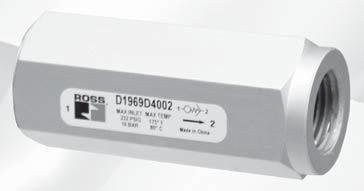
119 CONTROLS AIR-USE LOW DIUSERS
120 AIR-USE low Diffusers Minimize Hose Whip 9 Series The ROSS AIR-USE low Diffuser automatically reduces air flow to minimize hose whip. After a hose failure has occurred, the AIR-USE is designed to minimize the whip effect of the hose. A minimal amount of media flow will occur after the AIR-USE is triggered. This pilot flow will escape to atmosphere and continue until the AIR-USE is reset, therefore, the AIR-USE is intended to be used only with noncorrosive, non-flammable, non-hazardous gases. To reset the AIR-USE, simply shut-off the air supply. Air Supply AIR-USE Quick Disconnect Hose Ordering Information Proper sizing of the Air-use unit is guided by the air-operated work elements. Required flow rating must be ensured; i.e., flow capacity of the pneumatic element (pressure regulator, ball valve) installed upstream of the Air-use must be larger, than that of the used hose-break protection. Size ing Type Model Number* Shut-off low Rate at 00 psi (7 bar) scfm (dm /s) low at 00 psi (7 bar) P psi (0.07 bar) scfm (dm /s) Weight lb (kg) / emale-emale 969D ().8 (8) 0.09 (0.0) /8 emale-emale 969D () 8.6 () 0.5 (0.07) / emale-emale 969D00 0. (8) 9. () 0. (0.5) / emale-emale 969D (80) 9. () 0.8 (0.) emale-emale 969D (8) (68).9 (0.5) ½ emale-emale 969D (68) 07 (5).0 (.00) *NPT port threads. or SPP threads add a D prefix to the model number, e.g., D969D00. Valve Dimensions inches (mm).0 (5.) 0. (.0) 0.8 (0.6). (6.0) 0.0 (5.) 0.9 (.9) Size / 0.8 (0.6) Size /8 0.9 (.9) 0.9 (9.9).65 (8.) 0.0 (5.) 0.9 (9.9).00 (50.8) 0. (0.).5 (89.9) 0.0 (5.) 0. (0.).5 (.8) Size /.00 Size / (50.8).5 (.8) 0.66 (6.8) 0.66 (6.8) 0.56 (.) 0.56 (.) 7.65 (8.) 0.0 (5.).00 (50.8) 5.7 (5.0) 0.0 (5.).50 (6.5) Size.00 (50.8) Size ½.50 (6.5) 0.66 (6.8) 0.66 (6.8) 0.66 (6.8) 0.66 (6.8) Reduces the Dangers of Hose and Plastic Tubing ailure STANDARD SPECIICATIONS (for valves on this page): Ambient/Media Temperature: 5 to 75 ( to 80 C). or temperature below 5 ( C), consult ROSS. low Media: iltered air. Operating Pressure: Maximum psi (6 bar). Minimum according to hose length. Drop pressure at shut-off flow:. psi (0. bar). Mounting: In-line two-way valve. To be inserted between fixed air supply and flexible air lines Material: Housing: Aluminum. Inner parts: rass. Spring: Stainless Steel , ROSS CONTROLS. All Rights Reserved. Rev. 0/0/7
121 AIR-USE low Diffusers Minimize Hose Whip 9 Series Coiled Hose Selection Information Minimum Supply Working pressure based on hose length and diameter psig (bar) Model Number Size 969D00 / 969D00 /8 969D00 / 969D500 / 969D D800 ½ Important Notes: Hose Length feet (meter) 0.5 (0.08) 0. (0.0) 0.70 (0.) 0.70 (0.) Internal Hose Diameter inch (mm) (0.5) (0.8) (0.).000 (0.0).50 (0.8).500 (0.6) (.65) 70 (.8) (.) 7 (.7) 0 (0.69) 9 (0.6) 8 (0.55) 7 (0.8) 7 (0.8) 7 (0.8) 7 (0.8) 5 (7.6) 7 (9.5) 57 (.9) 7 (.86) (0.90) (0.76) 9 (0.6) 8 (0.55) 7 (0.8) 7 (0.8) 7 (0.8) 50 (5.) 07 (7.8) 7 (.) 9 (.) 5 (.0) (0.76) 8 (0.55) 7 (0.8) 7 (0.8) 7 (0.8) 00 (0.8) 07 (.7) 87 (6) 0 (.0) (.58) (0.96) 9 (0.6) 8 (0.55) 7 (0.8) 7 (0.8) (.65) (9.0) 57 (.9) (.5) 7 (.7) (0.76) 8 (0.55) 8 (0.55) 7 (0.8) 7 (0.8) 5 (7.6) (7.65) 7 (.55) 8 (.9) 6 (.0) 0 (0.69) 8 (0.55) 7 (0.8) 7 (0.8) 50 (5.) 5 (.8) ) 9 (.8) 5 (.7) (0.8) 8 (0.55) 8 (0.55) 7 (0.8) 00 (0.8) 6 (8.69) 9 (6.7) (.90) 7 (.7) 9 (0.6) 8 (0.55) 7 (0.8) (.65) 9 (8.0) 9 (.69) 0 (.07) 7 (.7) 0 (0.69) 8 (0.55) 7 (0.8) 7 (0.8) 5 (7.6) 7 (5.0) 5 (.7) 7 (.86) (0.90) 8 (0.55) 8 (0.55) 7 (0.8) 50 (5.) (9.7) 0 (7.0) 6 (.7) 9 (.) 0 (0.69) 8 (0.55) 8 (0.55) 00 (0.8) 96 (.5) 85 (5.86) 9 () (0.8) 9 (0.6) 8 (0.55) (.65) 96 (6.6) 70 (.8) (.7) 5 (.0) 9 (0.6) 8 (0.55) 7 (0.8) 5 (7.6) 9 (.) 9 (9.58) 6 (.7) (.58) (0.76) 8 (0.55) 8 (0.55) 50 (5.) 6 (8) 8 (.6) (0.97) 9 (0.6) 8 (0.55) 00 (0.8) (5.) 69 (.76) 0 (.8) (0.76) 9 (0.6) (.65) (5.9) 66 (8) 7 (5.0) 6 (.79) (0.76) 8 (0.55) 8 (0.55) 5 (7.6) (9.9) 7 (.) 6 (.0) 0 (0.69) 8 (0.55) 50 (5.) 85 (5.86) (.65) (0.8) 9 (0.6) 00 (0.8) 6(.) (0.96) 7 (.7) (0.76) (.65) 89 (6.) 5 (.7) (0.89) 9 (0.6) 5 (7.6) 79 (.) (.0) 8 (.) (0.8) 50 (5.) 8 (5.58) 0 (.8) 6 (.0) 00 (0.8) 5 (0.6) 5 (.58) (.65) low is automatically reduced to a non-hazardous level after the ROSS AIR-USE has sensed a broken hose or tube. Until the supply of the compressed media is turned off, a nominal amount of flow will occur through the AIR-USE, therefore use only with non-corrosive, non-flammable and non-hazardous gases (check material compatibility). AIR-USE size should equal hose inside diameter. No reduced fittings should be used downstream of the AIR-USE before the tool. low-reducing fittings may only be used if they are directly connected with the work element. When applying the AIR-USE to a directional valve application, the valve should be oversized to eliminate excessive back pressure. 7 Compressed Air Inlet Compressed Air Outlet Rev. 0/0/7 7.
122 General Information Standard Specifications The standard specifications for the products on each page of this catalog are given on the same page or referenced. or solenoid pilot valves, models with internal pilot supply are listed. Most models are also available for use with external pilot supply or have a built-in pilot supply selector valve. The products in this catalog are intended for use in industrial pneumatic systems. Most products are adaptable to other uses and conditions not covered by the standard specifications given in this catalog. Weights shown are approximate and are subject to change. Dimensions given, unless otherwise noted, are envelope dimensions (not for mounting). Consult ROSS for further information. Threads s of valves and bases described in this catalog have NPT (ANSI.) threads. Other thread types can be specified by putting an appropriate prefix letter on the model or part number when ordering. Thread Types by Model Prefix Letter Pneumatic Prefix Threaded Electrical Threads Letter Opening NPT (ANSI.) None NPT ISO 8 - DIN 59 Parallel, SPP # C* ISO 8 - DIN 59 Parallel, SPP # D G ISO 8 - JIS 00 Tapered # J ISO SAE 96- ISO 96 S NPT * Used only for filters, regulators, lubricators. # ISO 8 threads superseds SPP, G and JIS thread types. low Ratings low ratings are expressed as C V where C V = corresponds to a steady state air flow of approximately scfm under the following conditions: Inlet pressure = 00 psig (6.7 bar) Pressure drop = 0 psi (0.69 bar) Air temperature = 68 (0 C) Relative humidity = 6% Note: ecause widely differing test standards are used to measure C V values, the figures given in this catalog should not be used to compare ROSS valves with those of other makers. The C V ratings given here are intended only for use with performance charts published by ROSS. The C V ratings are averages for the various flow paths through the valve and are for steady flow conditions. Approvals and Certifications ROSS products are designed to meet a number of industrial standards, including the Canadian Standards Association (C.S.A.) guidelines. or more information on specific product approvals, contact your local distributor or ROSS. Solenoids All ROSS standard solenoids are rated for continuous duty (unless noted otherwise) and will operate the valve within the air pressure range specified in this catalog. Explosion-Proof Solenoid Pilot available, for more information consult ROSS. Voltage & Hertz When ordering a solenoid valve, also specify the desired solenoid voltage and hertz. Voltage Types by Model Suffix Letter Voltage Suffix Letter 0 volts AC Z 0 volts AC Y volts DC H volts DC W 8 volts DC M 90 volts DC K 0 volts DC P 5 volts DC C Recommended Solenoid Voltages: 00-0 volts AC, 50 Hz; 00-0 volts AC, 60 Hz; volts DC; 0 volts DC. In addition, the following voltages are available: 00, 0 volts AC, 50 Hz 00, 0, 80 volts AC, 60 Hz, 8, 0 volts AC, 50 Hz 0 volts AC, 60 Hz 00, 0 volts AC, 50 Hz 00, 0 volts AC, 60 Hz. or example: Model 77500, 0 volts AC, 60 Hz. Model W60760, 0 volts AC, 50 Hz. or additional information or help with voltage configuration, please contact your local distributor or ROSS. Identification Valve symbols in this catalog conform to the ISO 9-:99 standard of the International Organization for Standardization (ISO) and the SAE J05 standard of the Society of Automotive Engineers (SAE) respectively. Information or Technical Assistance or additional information or application assistance concerning ROSS products, consult ROSS or your local ROSS distributor (see contact information on the back cover). Order Placement or order placement, consult ROSS or your local ROSS distributor. or a current list of countries and local distributors, visit ROSS website at. 0 Rev. 0/07/7
123 CAUTIONS, WARNINGS and STANDARD WARRANTY PRE-INSTALLATION or SERVICE. efore servicing a valve or other pneumatic component, be sure that all sources of energy are turned off, the entire pneumatic system is shut off and exhausted, and all power sources are locked out (ref: OSHA 90.7, EN 07).. All ROSS products, including service kits and parts, should be installed and/or serviced only by persons having training and experience with pneumatic equipment. ecause any installation can be tampered with or need servicing after installation, persons responsible for the safety of others or the care of equipment must check every installation on a regular basis and perform all necessary maintenance.. All applicable instructions should be read and complied with before using any fluid power system in order to prevent harm to persons or equipment. In addition, overhauled or serviced valves must be functionally tested prior to installation and use. If you have any questions, call your nearest ROSS location listed on the cover of this document.. Each ROSS product should be used within its specification limits. In addition, use only ROSS parts to repair ROSS products. WARNING: ailure to follow these directions can adversely affect the performance of the product or result in the potential for human injury or damage to property. ILTRATION and LURICATION 5. Dirt, scale, moisture, etc. are present in virtually every air system. Although some valves are more tolerant of these contaminants than others, best performance will be realized if a filter is installed to clean the air supply, thus preventing contaminants from interfering with the proper performance of the equipment. ROSS recommends a filter with a 5-micron rating for normal applications. 6. All standard ROSS filters and lubricators with polycarbonate plastic bowls are designed for compressed air applications only. Do not fail to use the metal bowl guard, where provided, to minimize danger from high pressure fragmentation in the event of bowl failure. Do not expose these products to certain fluids, such as alcohol or liquefied petroleum gas, as they can cause bowls to rupture, creating a combustible condition, hazardous leakage, and the potential for human injury or damage to property. Immediately replace a crazed, cracked, or deteriorated bowl. When bowl gets dirty, replace it or wipe it with a clean dry cloth. 7. Only use lubricants which are compatible with materials used in the valves and other components in the system., compatible lubricants are petroleum based oils with oxidation inhibitors, an aniline point between 80 (8 C) and 0 (0 C), and an ISO, or lighter, viscosity. Avoid oils with phosphate type additives which can harm polyurethane components, potentially leading to valve failure which risks human injury, and/or damage to property. AVOID INTAKE/EXHAUST RESTRICTION 8. Do not restrict the air flow in the supply line. To do so could reduce the pressure of the supply air below the minimum requirements for the valve and thereby cause erratic action. 9. Do not restrict a valve s exhaust port as this can adversely affect its operation. Exhaust silencers must be resistant to clogging and must have flow capacities at least as great as the exhaust capacities of the valves. Contamination of the silencer can result in reduced flow and increased back pressure. WARNING: ROSS expressly disclaims all warranties and responsibility for any unsatisfactory performance or injuries caused by the use of the wrong type, wrong size, or an inadequately maintained silencer installed with a ROSS product. POWER PRESSES 0. Mechanical power presses and other potentially hazardous machinery using a pneumatically controlled clutch and brake mechanism must use a press control double valve with a monitoring device. A double valve without a self-contained monitoring device should be used only in conjunction with a control system which assures monitoring of the valve. All double valve installations involving hazardous applications should incorporate a monitoring system which inhibits further operation of the valve and machine in the event of a failure within the valve mechanism. ENERGY ISOLATION/EMERGENCY STOP. Per specifications and regulations, ROSS L-O-X and L-O-X with EEZ-ON operation products are defined as energy isolation devices, NOT AS EMERGENCY STOP DEVICES. All products sold by ROSS CONTROLS are warranted for a one-year period [with the exception of all ilters, Regulators and Lubricators ( RLs ) which are STANDARD WARRANTY warranted for a period of seven years] from the date of purchase to be free of defects in material and workmanship. ROSS obligation under this warranty is limited to repair or replacement of the product or refund of the purchase price paid solely at the discretion of ROSS and provided such product is returned to ROSS freight prepaid and upon examination by ROSS is found to be defective. This warranty becomes void in the event that product has been subject to misuse, misapplication, improper maintenance, modification or tampering. THE WARRANTY EXPRESSED AOVE IS IN LIEU O AND EXCLUSIVE O ALL OTHER WARRANTIES AND ROSS EXPRESSLY DISCLAIMS ALL OTHER WARRANTIES EITHER EXPRESSED OR IMPLIED WITH RESPECT TO MERCHANTAILITY OR ITNESS OR A PARTICULAR PURPOSE. ROSS MAKES NO WARRANTY WITH RESPECT TO ITS PRODUCTS MEETING THE PROVISIONS O ANY GOVERNMENTAL OCCUPATIONAL SAETY AND/OR HEALTH LAWS OR REGULATIONS. IN NO EVENT IS ROSS LIALE TO PURCHASER, USER, THEIR EMPLOYEES OR OTHERS OR INCIDENTAL OR CONSEQUENTIAL DAMAGES WHICH MAY RESULT ROM A REACH O THE WARRANTY DESCRIED AOVE OR THE USE OR MISUSE O THE PRODUCTS. NO STATEMENT O ANY REPRESENTATIVE OR EMPLOYEE O ROSS MAY EXTEND THE LIAILITY O ROSS AS SET ORTH HEREIN. Rev. 0/07/7


124 ROSS CONTROLS U.S.A. Tel: Customer Svs GET-ROSS (8-7677) Technical Svs TEK-ROSS ( ) ROSS EUROPA GmbH Germany Tel: ROSS ASIA K.K. Japan Tel: ROSS UK Ltd. United Kingdom Tel: ROSS CONTROLS INDIA Pvt. Ltd. India Tel: ROSS SOUTH AMERICA Ltda. razil Tel: ROSS RANCE SAS rance Tel: ROSS CONTROLS (CHINA) Ltd. China Tel: ROSS CANADA Canada Tel: CANADA INC. An Independent Representative ull-service Global Locations There are ROSS Distributors Throughout the World To meet your requirements across the globe, ROSS distributors are located throughout the world. Through ROSS or its distributors, guidance is available for the selection of ROSS products, both for those using pneumatic components for the first time and those designing complex pneumatic systems. Other literature is available for engineering, maintenance, and service requirements. If you need products or specifications not shown here, please contact ROSS or your ROSS distributor. They will be happy to assist you in selecting the best product for your application. or a current list of countries and local distributors, visit ROSS website at. U.S.A. - Content subject to change. Online version only. 07, ROSS CONTROLS. All Rights Reserved. orm ROSS-SA0
CONTROLS ROSS SAFETY-RELATED PRODUCTS
 CONTROLS ROSS SAETY-RELATED PRODUCTS Lockout & Exhaust and Soft-Start Valves Sensing Valves Double Valves for Control Reliable Energy Isolation Pilot Operated Check Valves Double Valves for Cylinder Return
Energy Isolation Lockout & Soft Start Valves ROSS CONTROLS
 Lockout & Soft Start Valves ROSS CONTROLS MANUAL LOCKOUT & EXHAUST L-O-X S KEY EATURES luorocarbon slipper seals for easy shifting, even after long periods of inactivity Easily identified by yellow body
Pneumatic Machine Safeguarding Solutions
 BULLETIN 50 C Pneumatic Machine Safeguarding Solutions Complete Your System with ROSS CONTROLS Safety-Related Products CONTENT Page Pneumatic Energy Isolation Lockout and Lockout with Soft Start Valves
Product Information. Stainless Steel. L-O-X 15 Series ROSS CONTROLS
 Product Information Stainless Steel Lockout Valves L-O-X 15 Series ROSS CONTROLS Manual Lockout & Exhaust L-O-X Valves Stainless Steel Energy Isolation 15 Series 3-Way 2-Position Valve Port Size Valve
ROSS CONTROLS. Double Valves for Control Reliable Energy Isolation.
 ROSS CONTROLS Double Valves for Control Reliable Energy Isolation DM and DM Series CONTROL RELILE DOULE VLVES DM SERIES KEY ETURES Rapid response time to minimize stopping time Status Indicator switch
ROSS CONTROLS. Double Valves for Control Reliable Energy Isolation.
 ROSS CONTROLS Double Valves for Control Reliable Energy Isolation DM and DM Series CONTROL RELILE DOULE VLVES DM SERIES KEY ETURES Rapid response time to minimize stopping time Status Indicator switch
Safe Cylinder Control and Stop and Load Holding Valves ROSS CONTROLS
 Safe Cylinder Control and Stop and Valves ROSS CONTROLS SAE CYLINDER CONTROL AND STOP CrossCheck TM DOUBLE VALVES, CC4 SERIES KEY EATURES Closed Center valve function Redundant control with position feedback
Control Reliable Double Valves with Total Dynamic Monitoring & Complete Memory
 Control Reliable Double Valves Safety Exhaust (Dump) DM Series D Self Monitored - Clutch/rake Control asic Size,,, and 0 Dynamic Monitoring With Complete Memory: Memory, monitoring, and air flow control
Control Reliable Monitored Valves
 Safety Exhaust Control Reliable Monitored Valves ROSS CONTROLS CONTROL RELILE DOULE VLVES M SERIES KEY ETURES: Pressure sensors allow for external monitoring of valve state Modular or threaded port connection
Product Information. L-O-X 15 Series ROSS CONTROLS
 Product Information Lockout Valves L-O-X 5 Series ROSS CONTROLS Manual Lockout & Exhaust L-O-X Valves Slim-Line Energy Isolation 5 Series -Way -Position Valve Port Size Valve Model Number C V Weight lb
CONTROLS SAFETY EXHAUST (DUMP) CONTROL RELIABLE ENERGY ISOLATION DOUBLE VALVES M35, DM 1, DM 2 SERIES.
 CONTROL RELIABLE ENERGY ISOLATION DOUBLE VALVES M35, DM 1, DM 2 SERIES.") CONTROLS SETY EXHUST (DUMP) CONTROL RELILE ENERGY ISOLTION DOULE VLVES M, DM, DM SERIES www.rosscontrols.com CONTROL RELILE DOULE VLVES M SERIES KEY ETURES: Pressure sensors allow for external monitoring
CONTROLS SETY EXHUST (DUMP) CONTROL RELILE ENERGY ISOLTION DOULE VLVES M, DM, DM SERIES www.rosscontrols.com CONTROL RELILE DOULE VLVES M SERIES KEY ETURES: Pressure sensors allow for external monitoring
Product Information ROSS CONTROLS
 Product Information Safe Cylinder Return Double s CrossMirror ROSS CONTROLS with Dedicated Reset Solenoid Pilot Controlled Safe Cylinder Return Port Size Basic Size Status Indicator Pressure Switch without
ROSS CONTROLS. CrossMirror 77 And CM Series. Double Valves for Cylinder Return to Home Position.
 ROSS CONTROLS Double s for Cylinder Return to Home Position CrossMirror 77 And CM Series 5/2 PRESSURE RETURN KEY EATURES Can be used as /2 Normally Closed or /2 Normally Open valve function by plugging
ROSS CONTROLS.
 ROSS CONTROLS Sensing Valves SV27 Series 2 SENSING VALVES KEY EATURES Senses internal position & state Electrical feedback via DPST switch ( Double-Pole Single-Throw) Directly operated safety-rated force-guided
Hazardous Locations ROSS CONTROLS
 Hazardous Locations Explosion-Proof Valves ROSS CONTROLS DIRECTIONAL CONTROL POPPET & 7 SERIES EXPLOSION PROO VALVES KEY EATURES Series - Construction - Metal, Aluminum 7 Series - Construction - Acetal
ROSS CONTROLS. Explosion Proof Valves 27 & 21 Series, DM 2 Series C. ISO Valves W60 & W64 Series.
 ROSS CONTROLS Valves 7 & Series, DM Series C ISO Valves W60 & W64 Series POPPET 7 & SERIES EXPLOSION PROO VALVES KEY EATURES 7 Series - Construction - Acetal internals Series - Construction - Metal, Aluminum
ROSS CONTROLS. Pilot Operated Check Valves 19, 27 and SV27 Series.
 ROSS CONTROLS Pilot Operated Check Valves 9, 7 and SV7 Series PILOT OPERATED CHECK VALVES RIGHT ANGLE KEY EATURES Right angle design for easy positioning of pipe or tubing Threaded outlet ports available
P33T Series Redundant Safety Exhaust Valve ENGINEERING YOUR SUCCESS.
 aerospace climate control electromechanical filtration fluid & gas handling hydraulics pneumatics process control sealing & shielding P33T Series Redundant Safety Exhaust Valve Catalogue PDE675TCUK October
P33T Series Redundant Safety Exhaust Valve ENGINEERING YOUR SUCCESS. Bulletin 0700-B13.
 aerospace climate control electromechanical filtration fluid & gas handling hydraulics pneumatics process control sealing & shielding P33T Series Redundant Safety Exhaust Valve Bulletin 0700-B3 ENGINEERING
Product Information. Safety Exhaust ROSS CONTROLS
 Product Information Safety Exhaust Double Valves M DM2 Series C ROSS CONTROLS Control Reliable Double Valves with Dynamic Monitoring and Memory Safety Exhaust (Dump) M DM 2 Series C F2 3/2 Double Valves
ROSS CONTROLS. Poppet Valves 21 Series. High Temperature and Low Temperature Applications.
 ROSS CONTROLS Poppet Valves High Temperature and Low Temperature Applications POPPET 21 SERIES VALVES KEY FEATURES Low weight; compact size Available with choices of internal components for three different
BULLETIN 510. The Guiding Light to Pneumatic Machine Safeguarding. Complete Your System with ROSS CONTROLS Safety-Related Products.
 BULLETIN 510 The Guiding Light to Pneumatic Machine Safeguarding. Complete Your System with ROSS CONTROLS Safety-Related Products. Where Does Your Safety System End? A Complete Safety System should always
Product Information ROSS CONTROLS. Cylinder Position and Load Holding. 19 & 27 Series
 Product Information Position and PO Check Valves 9 & 7 Series ROSS CONTROLS Pilot Operated Check Valves Right-Angle with Threaded Banjo Size (female threads) (male threads) Threads Models with Threaded
BULLETIN. Manufacturers of Premium Pneumatic Controls since 1921
 ULLETIN ENERGY-ISOLTION & EEZ-ON PRODUTS L-O-X Valves EEZ-ON Valves L-O-X Valves with EEZ-ON Operation Manufacturers of Premium Pneumatic ontrols since 9 7 Regulations for Workplace Safety The Occupational
ROSS CONTROLS. Double Valves for Clutch/Brake Control
 ROSS CONTROLS Double Valves for Clutch/rake Control DM Series D and 5 Series Contents ge DM Series Double Valves for Control Reliable Energy Isolation. -.8 With Dynamic Monitoring & Memory DM Series D
Product Information. RSe Series ROSS CONTROLS
 Product Information Safe Cylinder Return Double Valves RSe Series ROSS CONTROLS Control Reliable Double Valves for External Monitoring RSe Series Safe Cylinder Return 5/2 Redundant Double Valve Sub-base
Product Information ROSS CONTROLS
 Product Information Safe Cylinder Return Double Valves CrossMirror 77 Series ROSS CONTROLS CrossMirror Control Reliable Double Valves with Automatic Reset Solenoid Pilot Controlled Safe Cylinder Return
Product Information. Safety Exhaust ROSS CONTROLS
 Product Information Safety Exhaust Double Valves DM Series E ROSS CONTROLS Control Reliable Double Valves with Dynamic Monitoring and Memory Safety Exhaust (Dump) DM Series E Dynamic Monitoring with Memory:
Product Information. Safety Exhaust. DM 2 Series C ROSS CONTROLS
 Product Information Safety Exhaust Double Valves DM Series C ROSS CONTROLS Control Reliable Double Valves with Dynamic Monitoring and Memory Safety Exhaust (Dump) DM Series C asic Size,,, and 0 Dynamic
Directional Control Valves ROSS CONTROLS
 Directional Control Valves Slim-Line 9 Series ROSS CONTROLS IN-LINE DIRECTIONAL VALVES AND MANIFOLDS KEY FEATURES volts DC and volts AC options for solenoid control Available with /8, /, /8, and / port
ROSS CONTROLS. 95 Series. Inline Directional Control Valves.
 ROSS CONTROLS Inline Directional Control Valves 9 Series INLINE DIRECTIONAL VALVES AND MANIFOLDS KEY FEATURES volts DC and volts AC options for solenoid control Available with /8, /, /8, and / port options
Product Information. 36 & RM Series ROSS CONTROLS
 Product Information oot Operated Valves 36 & RM Series ROSS CONTROLS Manual Valves Pedal & Treadle Heavy-Duty 36 Series 3-Way 2-Position Valves, Pedal, Spring Return NPT Threads BSPP Threads 1-2 2-3 1/4
Product Information. 16 Series ROSS CONTROLS
 Product Information Compact Valves 16 Series ROSS CONTROLS Compact Valves Solenoid Pilot Controlled 16 Series -Way -Position Valves, Spring Return C V Average Response Constants** 1,, NPT Threads BSPP
Compact Valves 16 Series
 Compact Valves 16 Series ROSS CONTROLS B Compact Valves Solenoid Pilot Controlled 16 Series Port Size Normally Closed Valve Model Number# 1 3-Way -Position Valves, Spring Return 3 1 Normally Open Valve
ROSS CONTROLS. Compact Valves 16 Series.
 ROSS CONTROLS Compact Valves 6 Series B B5 Solenoid Pilot Controlled Compact Valves 6 Series -Way -Position Valves, Spring Return Port Size Valve Model Number* C V Weight,, Normally Closed (NC) Normally
Product Information ROSS CONTROLS
 Product Information Minimize Hose Whip Flow Diffuser AIR-FUSE 19 Series ROSS CONTROLS AIR-FUSE Flow Diffusers Minimize Hose Whip 19 Series The ROSS AIR-FUSE Flow Diffuser automatically reduces air flow
2oo2 with bypass valve exhaust guards and indicators. 2oo2 I4. N/en
 V8 series Redundant valve manifold systems - Modular with bypass oo Safety, oo Availability and oo Safety and Availability Modular design - Maxseal valves ypass function enables valve removal online Stainless
Lockout Valves. Section C. Pneumatic
 Lockout Valves Section LV Series Basic Features... Applications... Mounting... Dimensions... LV Series Technical Information Operation... Specifications... Ordering Information... EZ Series Basic Features...4
ROSS CONTROLS. Base Mounted Valves. and Serial Bus Communication
 ROSS CONTROLS Base Mounted Valves and Serial Bus Communication ISO 15407-1 & 2 ISO 5599/I & /II Serial Communications VLVE TYPE NSI SE Miniature 14 Series Solenoid Pilot Valves Pack VLVE SERIES DESCRIPTION
Redundant Control System
 Redundant Control System Safety instrumented system applications up to SIL 3 Process reliability Process valve diagnostics COMPLETE FUNCTIONAL SAFETY WITH ENHANCED RELIABILITY The Redundant Control System
Clutch/Brake Control Monitored Double Valves
 Clutch/Brake Control Monitored Double Valves ROSS CONTROLS DM Monitoring: The DM is a patented / normally closed valve (with an intermediate, lockout position) distinguished by SERPAR Crossflow passages
4 Redundant Control System
 4 Redundant Control System Introducing the all NEW RCS Configurator Safety Instrumented Systems Process Reliability Process Valve Diagnostics COMPLETE FUNCTIONAL SAFETY WITH ENHANCED RELIABILITY The Redundant
Series AV2000/3000/4000/5000
 Soft Start-up Valve Series AV/3/4/5 Series introduced! A start-up valve that gradually increases supply pressure during start up and rapidly exhausts system air when the supply air is shut off AC AV AU
ValVes for air flow Control
 ROSS CONTROLS Valves for Air Flow Control Flow Control Valves Check Valves D D1 Shuttle Valves Quick Exhaust Valves VALVE TYPE VALVE SERIES AVAILABLE PORT SIZES 1/8 1/4 3/8 1/ 3/4 1 11/4 11/ 1/ MAX. FLOW
CONTROLS VALVES FOR AIR FLOW CONTROL
 CONTROLS VALVES FOR AIR FLOW CONTROL Flow Control Valves Check Valves D D1 Shuttle Valves Quick Exhaust Valves VALVE TYPE VALVE SERIES AVAILABLE PORT SIZES 1/8 1/4 3/8 1/ 3/4 1 1¼ 1½ ½ MAX. FLOW Cv Page
95 Series Inline Directional Control Valves Manufacturers of Premium Pneumatic Controls since 1921
 ROSS CONTROLS 9 Series Inline Directional Control Valves Manufacturers of Premium Pneumatic Controls since 9 9 Series Valves INLINE DIRECTIONAL VALVES AND MANIFOLDS KEY FEATURES /-, /- and / way Solenoid
Product Information ROSS CONTROLS
 Product Information Explosion-Proof Safety Exhaust Double Valves DM2 Series C ROSS CONTROLS Explosion-Proof Control Reliable Double Valves with Dynamic Monitoring & Memory DM 2 Series C Safety Exhaust
Installation Components AirCare Air Preparation Systems
 Care Preparation Systems Modular Line Filters 602104 602106 602108 * Transparent 602109 nylon liquid level indicator -18 lens. to 79 C Body Bowl Material icle Zinc Aluminum Zinc* Aluminum* Sintered Polypropylene
ROSS CONTROLS. 95 & 34 Series.
 ROSS CONTROLS NAMUR Interface Valves 95 & 34 Series B NAMUR INTERFACE 95 SERIES VALVES KEY FEATURES Compact inline ported valve consisting 5/2-way with either solenoid pilot control 24 volts DC and 110
ROSS CONTROLS.
 ROSS CONTROLS AIR-FUSE Flow Diffusers www.rosscontrols.com AIR-FUSE Flow Diffusers 19 Series Minimize Hose Whip The ROSS AIR-FUSE Flow Diffuser automatically reduces air flow to minimize hose whip. After
BULLETIN 200. Inline Poppet Valves Leak Tight Valves & Manifolds. Manufacturers of Premium Pneumatic Controls since 1921
 BULLETIN 00 Inline Poppet Valves Leak Tight Valves & Manifolds Manufacturers of Premium Pneumatic Controls since 9 Contents ROSS Poppet Valves...3 Why do Poppet Valves Pop?...4 Features Dale Series CP
Product Information. W66 Series ROSS CONTROLS
 Product Information ISO 15407-1 Valves ROSS CONTROLS Solenoid Pilot Controlled Valves 5-Way 2-Position Valves, Single Solenoid Pilot Controlled, Spring Return HOW TO ORDER (Choose your options (in red)
ACCESSORIES FOR AIR VALVES & AIR SYSTEMS
 ACCESSORIES FOR AIR VALVES & AIR SYSTEMS BULLETIN ACC-2000R AIR VALVES FOR INDUSTRY SINCE 1949 ISO 9001 CERTIFIED FOOT GUARDS Page 8 QUICK EXHAUST & ELECTRIC QUICK EXHAUST VALVES Pages 6 & 7 SHUTTLE VALVES
ROSS CONTROLS. Double Valves for Clutch/Brake Control.
 ROSS CONTROLS Double Valves for Clutch/rake Control SERPR Crossflow 5 Series SERPR CROSSFLOW DOULE VLVES 5 SERIES WITH PRESSURE SWITCHES FOR EXTERNL MONITORIN KEY FETURES Designed to enable users to comply
Mini 1. Compact High Flow 3-Way and 4-Way Pneumatic Directional Control Valves
 Catalog LX-530 Mini 1 Compact High Flow and Pneumatic Directional Control Valves FEATURES: 3-port or 5-port bodies Manual, Air Pilot, Solenoid or Mechanical Operators Two-position, Single or Dual Actuation
PACKED SPOOL 4-WAY DIRECTIONAL CONTROL VALVE.
 PACKED SPOOL 4-WAY DIRECTIONAL CONTROL VALVE www.elwood.com 0 0 1 : 0 0 0 C E R T I F I E D C O M P A N Y 4-Way 3-Postion Valve 4-WAY, 3-POSITION DIRECTIONAL VALVE, AIR SOLENOID OPERATED SHOWN; DIRECT
3/8 & 1/2 NPT. with 3/8 and 1/2 NPT ports for 4 Way - 2 & 3 Position see Pg locate counterbores in body to control static squeeze on seals.
 8 SERIES /8 Ported Air Valves 1/ Ported Air Valves /8 & 1/ 1, 1A, 1B & 8 Series Note! Spring return & spring centered models NOT suitable for dry air service. Features & Way - Position. Way - &. operator
3/2-, 5/2- and 5/3-way Solenoid Valves for process pneumatics
 /-, 5/- 5/-way Solenoid Valves for process pneumatics Type 658 stard High flow-rate capacity Reduced power consumption Single or manifold mounting stard Type 658/659 can be combined with... Stard-, EEx
Series VZ Port Solenoid Valve Body Ported. How to Order VK VZ VF VFR VP4 VZS VFS VS4 VQ7 EVS VFN. Body ported VZ L
 Port Solenoid Valve Body Ported Series 000 For details about certified products conforming to international standards, visit us at www.smcworld.com. Type of actuation Type of actuation Rated voltage Body
LIMIT SWITCH Axiom - AX
 LIMIT SWITCH Axiom - AX with SST Switching Sensors Installation, Maintenance and Operating Instructions (AX33 ) Publication# 10532revB 2 Table of Contents Publication# 10532revB Table Of Contents... Page
Type 2511/12. Type Type 2030 Cable plug. ASI cable plug. Dosing control. General technical data Orifice Type 6518
 3/2-, 5/2- and 5/3-way Solenoid Valves for process pneumatics Type 658 standard standard High flow-rate capacity Reduced power consumption Single or manifold mounting Standard-, EEx m and EEx i versions
Safety Exhaust Valve Integration Guide
 Safety Exhaust Valve Integration Guide FRL-SIF-625 the total systems approach to air preparation Table of Contents Integration Guide Wilkerson E28/Q28 Safety Exhaust Valve General Information Introduction......
3/2-, 5/2- and 5/3-way Solenoid Valves for process pneumatics
 /2-, 5/2-5/-way Solenoid Valves for process pneumatics Type 658 stard High flow-rate capacity Reduced power consumption Single or manifold mounting stard Type 658/659 can be combined with... Stard-, EEx
% ^ ) 4/2 SERIES. Direct Mount. Direct Acting Direct Mount Pilot Valves. Brass or Stainless Steel Bodies 1/4" NPT. Features. Construction.
 4/2 SERIES. Direct Mount. Direct Acting Direct Mount Pilot Valves. Brass or Stainless Steel Bodies 1/4 NPT. Features. Construction.") Direct Acting Direct Mount Pilot Valves Brass or Stainless Steel Bodies /" NPT / 83 Direct Mount Features NAMUR direct mount version of the rugged, dependable 83 Series valves Direct acting, high flow
Direct Acting Direct Mount Pilot Valves Brass or Stainless Steel Bodies /" NPT / 83 Direct Mount Features NAMUR direct mount version of the rugged, dependable 83 Series valves Direct acting, high flow
POWER PULSE VALVES integral pilot (external exhaust) threaded or Quick Mount connection 3/4 to 1 1/2
 threaded or Quick Mount connection 3/4 to 1 1/2") POWER PULSE VALVES integral pilot (external exhaust) threaded or Quick Mount connection 3/4 to 1 1/2 NC 2/2 Series 353 X003GB2009/R8 EATURES The piston cartridge pulse valves are especially designed for
POWER PULSE VALVES integral pilot (external exhaust) threaded or Quick Mount connection 3/4 to 1 1/2 NC 2/2 Series 353 X003GB2009/R8 EATURES The piston cartridge pulse valves are especially designed for
95 & 34 Series ROSS CONTROLS
 NAMUR Interface Valves 95 & 34 Series ROSS CONTROLS B NAMUR INTERFACE 95 SERIES VALVES KEY FEATURES Compact in-line ported valve consisting 5/2-way with either solenoid pilot control 24 volts DC and 110
26230, NAMUR 3/2 & 5/2 Indirect solenoid actuated spool valves
 60, 8007 NAMUR / & / > > Port size: G/ and NAMUR interface > > Easily interchangeable solenoid system > > For single and double operated actuators > > Standard manual override with detent > > Maintenance-free
Electrically operated valves Series BM-01, 3/2-way and 2 x 3/2-way G1/8 550 to 660 Nl/min (0.559 to Cv)
") Electrically operated valves Series BM-01, 3/2-way and 2 x 3/2-way G1/8 550 to 660 Nl/min (0.559 to 0.671 Cv) Order code BM-01-310-HNR-462 Series and function BM = Standard Manual override HNT = non-detented
Electrically operated valves Series BM-01, 3/2-way and 2 x 3/2-way G1/8 550 to 660 Nl/min (0.559 to 0.671 Cv) Order code BM-01-310-HNR-462 Series and function BM = Standard Manual override HNT = non-detented
Port Flow Rate/ Function Series Actuators Page Number Size Factor
 Section dex Port Flow Rate/ Function Series Actuators Page Number Size Factor 0- Cv = 0.05 Way Modular Solenoid. -. & to Way Manifold /8 NPT Cv = 0. Way, Position Modular /8 NPT Cv = 0.05 Way Hex Solenoid.5.6
VAL /4" to 2" Solenoid Pilot Actuated 2/2, 3/2, & 4/2 Inline Valves. Solenoid pilot operated spring return inline valves with nonlocking
 1/4" to 2" Solenoid Pilot ctuated VLVES High flow - Cv of 1.2 to 49.5 Durable, robust construction 1/4" to 2" ports (SPP, PTF, or ISO Rc threads) Wide range of voltages available Four functional types:
Transmitters: Relay Valve VR4151/4152
 Relay Valve VR4151/4152 Appropriate output sequences are affected according to the signal received from the mechanical valve. VR4151 VR4152 Precautions Be sure to read before handling. Refer to pages 5-11-2
Deep Well Pump Control Valve
 MODEL 61-02 661-02 Deep Well Pump Control Valve Prevent Surges in Pipelines Simple Hydraulic Operation Adjustable Opening & Closing Speeds Solenoid Control Can Be Operated Manually Proven Reliable Design
Direct solenoid and solenoid pilot operated valves
 Direct solenoid and solenoid pilot operated valves Individual mounting Series inline inline hazardous location Manifold mounting 35 sub-base non plug-in sub-base with pressure regulators sub-base hazardous
SOLENOID VALVES AND PNEUMATIC VALVES
 A S E R I E S Catalogue 001 Directly operated solenoid valves Series A / way, 3/ way monostable, stable (with magnetic memory) Ports M5, G1/8, cartridge ø 4 The Series A solenoid valves are of the directly
Customized Solutions. Safety & Reliability Stainless steel 316 products
 Customized Solutions Safety & Reliability Stainless steel 316 products REDUNDANT CONTROL SYSTEM (RCS) Applications Emergency Shutdown Systems Burner Management Systems Isolation and Venting Systems High
Booster Pump Control Valve
 MODEL 60-7 660-7 ooster Pump Control Valve Simple Hydraulic Operation Low Head Loss Horizontal or Vertical Mounting uilt-in Check Valve Proven Reliable Design The Cla-Val Model 60-7/660-7 ooster Pump Control
solenoid/air operated
 Series Modulair 0- range G/8 to G/ SHUT-O VLVE ND SOT- STRT UNIT solenoid/air operated Modulair 50 G/ - G version: See P0-9 PPLICTION This unit provides two main functions: - Pneumatic system venting.
2/2 Pressure operated valves
 Operation Series Page no. Function 2/2 3/2 Body material Stainless steel Brass Solenoids IP Protection class IP65 (with connector) Explosion proof class Zones 1, 21 II 2 GD EEx m IP67 II 2 G EEx me IP54
Power Valve: Economy Valve. Standard Specifications. Model VEX55-04
 Three functions (pressure regulator, switching valve, and speed controller) are provided by a single valve. The conventional valve combination circuit has been condensed into a single valve. A large capacity
The H Series Leak-Proof, High-Pressure Valves Versa Products Company has been supplying high quality pneumatic and hydraulic directional control valve
 High Pressure Valves Series H Bulletin H-Tech 0 VALVES The H Series Leak-Proof, High-Pressure Valves Versa Products Company has been supplying high quality pneumatic and hydraulic directional control valves
Instrument Ball Valves
 www.swagelok.com Instrument all s 40 Series On-off, switching, and crossover flow paths Working pressures up to 3000 psig (206 bar) Temperatures from 50 to 150 (10 to 65 ) Low-temperature service option
Solenoid Valves & Accessories. Cylinder Control Bases. Features. Performance Data. Materials
 Valves & Accessories PNEUMADYNE, INC. Catalog 00 Phone 76-559-077 Fax 76-559-057 Features l Controls cylinder extension and retraction l Allows rapid cylinder return l -Way Normally Closed l Quick Exhaust
Series 581 ISO Pneumatic Directional Control Valves
 Series 581 ISO 5599-1 Pneumatic Directional Control Valves Series 581 Pneumatic Valves 01_1 st Headline_36 pt/14.4 mm 4-Way ISO Directional Control second line Series 581 - A complete series of standardized
Electronic Control Valves
 MODEL 131 Series (Full Internal Port) 631 Series (Reduced Internal Port) Electronic Control Valves Model 131-01/631-01 Simple Proven Design Quality Solenoid Pilot Controls Ideal For SCADA Systems Multi-Function
Control & Power, Inc
 Way/ 2 and 3 Position Four ported valves are generally used to operate double-acting cylinders or actuators. They have four or five pipe connections, commonly called ports: One pressure inlet. Two cylinder
2/2-Way Pressure Relief Valve CX DBV (Right-Angle Design)
") 2/2-Way Pressure Relief Valve CX DBV (Right-Angle Design) CX DBV-E Model code (also example order) CX DBV 12 120 G1 F P 24V Type CX DBV = Pressure relief valve Nominal size 10 = DN 10 12 = 15 = 20 = CX
2/2-Way Pressure Relief Valve CX DBV (Right-Angle Design) CX DBV-E Model code (also example order) CX DBV 12 120 G1 F P 24V Type CX DBV = Pressure relief valve Nominal size 10 = DN 10 12 = 15 = 20 = CX
Electrically operated valves Series BM-01, 3/2-way and 2 x 3/2-way G1/8 550 to 660 Nl/min (0.559 to Cv)
") Electrically operated valves Series BM-01, 3/2-way and 2 x 3/2-way G1/8 550 to 660 Nl/min (0.559 to 0.671 Cv) Order code BM-01-310-HNR-462 Series and function BM = Standard Manual override HNT = non-detented
Electrically operated valves Series BM-01, 3/2-way and 2 x 3/2-way G1/8 550 to 660 Nl/min (0.559 to 0.671 Cv) Order code BM-01-310-HNR-462 Series and function BM = Standard Manual override HNT = non-detented
Common wiring modules can be connected by fieldbus, multi-pole or common earth/neutral modules.
 / and 4/ multi-way valves; servo assisted; DN 4; flow rate: l/min.; /8, legris ø 6 mm port connections Advantages / Benefits Optimised system solutions due to high level of modularity Compact design with
5 Port Pilot Operated Solenoid Valve Metal Seal, Body Ported
 For details about certified products conforming to international standards, visit us at www.smcworld.com. 5 Port Pilot Operated Solenoid Valve Metal Seal, Body Ported Series VFS2000 Model 2 position 3
200 SERIES THREADED VALVES PENTAIR CLEAN AIR SYSTEMS
 THREADED VALVES PENTAIR CLEAN AIR SYSTEMS Lock nut DESCRIPTION The is a range of diaphragm valves suitable for dust collector applications, in particular for reverse pulse-jet filter cleaning of filter
Electrically operated valves Series KM-09, 5/2- and 5/3-way G1/8 680 to 950 Nl/min (0.691 to Cv)
") Electrically operated valves Series KM-09, 5/2- and 5/3-way G1/8 680 to 950 Nl/min (0.691 to 0.966 Cv) Order code Series and function KM-09-510-HN-442 Standard coils HN at ports 2 + 4 HN at ports 1, 3
Electrically operated valves Series KM-09, 5/2- and 5/3-way G1/8 680 to 950 Nl/min (0.691 to 0.966 Cv) Order code Series and function KM-09-510-HN-442 Standard coils HN at ports 2 + 4 HN at ports 1, 3
Electrically operated valves Series BM-02, 3/2-way and 2 x 3/2-way G1/4 920 to 1090 Nl/min (0.935 to Cv)
") Electrically operated valves Series BM-02, 3/2-way and 2 x 3/2-way G1/4 920 to 1090 Nl/min (0.935 to 1.001 Cv) Order code BM-02-310-HNR-462 Series and function BM = Standard Manual override HNT = non-detented
Electrically operated valves Series BM-02, 3/2-way and 2 x 3/2-way G1/4 920 to 1090 Nl/min (0.935 to 1.001 Cv) Order code BM-02-310-HNR-462 Series and function BM = Standard Manual override HNT = non-detented
Electrically operated valves Series M-07, 3/2-, 5/2- and 5/3-way G1/ and 1580 Nl/min (1.321 and Cv)
") Electrically operated valves Series M-07, 3/2-, 5/2- and 5/3-way G1/4 1300 and 1580 Nl/min (1.321 and 1.606 Cv) Order code Series and function M-07-310-HN-442 Standard coil HN at port 2 + 4 HN at port
Electrically operated valves Series M-07, 3/2-, 5/2- and 5/3-way G1/4 1300 and 1580 Nl/min (1.321 and 1.606 Cv) Order code Series and function M-07-310-HN-442 Standard coil HN at port 2 + 4 HN at port
Manual and Mechanical Valves
 Manual and Mechanical Valves ROSS ONTROLS Pushbutton Palm Button Toggle Lever am Roller Plunger Hand Lever oot Pedal with Guard Pendant Accessories VALVE TYPE lush & Mushroom Pushbutton VALVE SERIES Palm
Series VP4 50/4 70. Large Size 5 Port Solenoid Valve Rubber Seal SJ SY SY SV SYJ SZ VF VP4 S0700 VQ VQ4 VQ5 VQC VQC4 VQZ SQ VFS VFR VQ7 VP4
 Type of actuation 4 Piping 0 Side ported Bottom ported 4 Without sub-plate Large Size 5 Port Solenoid Valve Rubber Seal Series 50/4 70 Series VP 5 port solenoid valve 5 7 position single position double
ANTI-SHOCK DIRECTIONAL CONTROL VALVES
 ACTUATED, DIRECT OPERATED TYPICAL PERFORMANCE SPECIFICATIONS Performance is measured on a four-way circuit (full circuit). Performance may e reduced from that shown if a three-way circuit (half circuit)
MN-06. Standardized valve series 3/2-way acc. to NAMUR, 750 Nl/min (0.762 Cv) Technical data for series. Order code MN HN-142
 Technical data for series. Order code MN HN-142") 3/2-way Technical data for series Order code -310-HN-142 Series and function Standard coil 1) (with plug socket 28-ST-01) 141 = 12 V DC, 4.2 W 142 = 24 V DC, 4.2 W 152 = 24 V AC, 7/4 VA 156 = 115 V AC,
3/2-way Technical data for series Order code -310-HN-142 Series and function Standard coil 1) (with plug socket 28-ST-01) 141 = 12 V DC, 4.2 W 142 = 24 V DC, 4.2 W 152 = 24 V AC, 7/4 VA 156 = 115 V AC,
PROCESS & AUTOMATED VALVES
 Process & utomated Valves HYDC s line of Process and utomated Valves complements our isolation valve knowhow and ability to supply high quality solutions to your valve requirements. 3-1 HV Series Inline
Double Acting & Spring Return. SERIES 92/93 Rack & Pinion PNEUMATIC ACTUATOR. The High Performance Company
 PNEUMATIC ACTUATOR SERIES 92/93 Rack & Pinion Double Acting & Spring Return The High Performance Company SERIES 92/93 Styling, strength, compactness, and simplicity of design have been combined to produce
MN-06. Standardized valve series 3/2-way acc. to NAMUR, 750 Nl/min (0.762 Cv) Technical data for series. Order code MN HN-142
 Technical data for series. Order code MN HN-142") Standardized valve series 3/2-way acc. to NAMUR, 750 Nl/min (0.762 Cv) Technical data for series Order code -310-HN-142 Series and function Standard coil 1) (with plug socket 28-ST-01) 141 = 12 V DC, 4.2
Standardized valve series 3/2-way acc. to NAMUR, 750 Nl/min (0.762 Cv) Technical data for series Order code -310-HN-142 Series and function Standard coil 1) (with plug socket 28-ST-01) 141 = 12 V DC, 4.2