Safety Exhaust Valve Integration Guide
|
|
|
- Everett Thornton
- 6 years ago
- Views:
Transcription


1 Safety Exhaust Valve Integration Guide FRL-SIF-625 the total systems approach to air preparation
2 Table of Contents Integration Guide Wilkerson E28/Q28 Safety Exhaust Valve General Information Introduction Exhaust Rate... 4 Soft Start... 5 Sensors & Gauges... 7 General Operation Guide (LED Status and Specifications) Operating Information Operation Monitoring Logic Validation Integration Guide (Safe Relay with Standard PLC for Cat 3 PL d) Rockwell (440R) Schmersal (SRB) Siemens (Sirius 3SK1112) Integration Guide (Programmable Safe Relay for Cat 4 PL e) Pilz (PNOZ) Rockwell Guardmaster (440C-CR30) Integration Guide (Safe PLC I/O for Cat 4 PL e) Rockwell ArmorBlock Guard (1732ES-IB8XOB8) Rockwell ArmorBlock Guard (1732ES-IB8XOBV4) Siemens (ET200PRO) Siemens (Simatic S7) Turck (TBPN)... 60
3 Integration Guide - Introduction Introduction Wilkerson offers a variety of safety valves for use in various safety functions such as safe exhaust, safe cylinder, return, and safe load holding/stop. This document focuses specifically on valves that use sensors to provide feedback to a safety control system for external monitoring. While all potential electrical safety control suppliers and solutions cannot be covered this document provides a template for the most common suppliers and their devices. Each solution has been designed to meet a specific category and performance level based on ISO Meeting this levels requires other aspects of the system meet these requirements such as but not limited to plumbing, wiring, and pulse testing. Pulse Testing In dual channel safety circuits, pulse testing is a method utilized to detect short circuit conditions that, without pulse testing, can mask other fault conditions. Pulse testing is required in dual channel circuits in order to reach performance level e (PL e). Pulse testing of the solenoids is encouraged and will not affect the performance of the Wilkerson valves. However, pulse testing of feedback sensors is not required. Wiring examples are provided in this document and are shown using specific connections as wired and tested, but there may be other terminals available to use on the various controllers. These are just examples. This integration guide is intended to assist you in integrating the product into your control circuit however; programs provided in this integration guide are for reference only. These programs have not been certified or tested unless indicated otherwise.

4 Integration Guide for Exhaust Rates Exhaust Times and Faulted Flow Rates When designing a safety circuit, the machine stopping time is critical to the placement of guarding equipment safe distance. One factor in safe distance calculations is the exhaust time of the valve that is responsible for isolating and dumping the pneumatic energy from the machine. The faster your valve exhausts the quicker the machine can stop and the closer your safety devices may be placed to the hazardous area. This can improve the overall operating efficiency, and possibly allow the footprint of the machine to be smaller. Even more important than exhaust times is the Faulted exhaust flow rate. Faulted exhaust flow rate is the exhaust rate of the valve in its worst state. Double valves (redundant valve systems used for safety applications) will not exhaust quite as quickly when there is an internal fault condition in the valve such as when one of the redundant valve components is actuated and the other one is not actuated. For this reason, double valves used in safety circuits should always be sized using faulted flow rates as the worst case condition. The chart below shows Wilkerson s very high flowing faulted exhaust flow times.
5 Integration Guide for Soft Start Adjustment Introduction The function of the optional soft start module is to, on energization, allow outlet pressure to increase at a slower than normal rate until it reaches approximately 60% of inlet pressure, at which point the valve will then open fully to finish filling the system at full flow rate. This feature can be used to lessen the shock of sudden, rapid pressurization of cylinders, and to gradually refill the system. The soft start module has an adjusting screw that is used to control the rate of pressurization according to number of turns and inlet pressure. The charts below can be used to approximate the number of turns (clockwise from full open) it will take in order to adjust the soft start for your system. The necessary setting is dependent upon the number of turns, inlet pressure, and downstream volume to be filled by the valve. E28/Q28
6 Integration Guide for Soft Start Adjustment Soft Start Adjustment Guide (Turns Versus Input Pressure) Measured in Nominal L/Min Turns 2 bar 4 bar 6 bar 8 bar 10 bar Full Open Measured in SCFM Turns 29 PSI 58 PSI 87 PSI 116 PSI 145 PSI Full Open

7 Integration Guide for Pressure Sensors & Gauges Gauge Port Details Safety Valves are available in BSPP or NPT threads. The thread selected for porting will be the threads used for the gauge port. BSPP = 1/8 BSPP gauge port NPT = 1/8 gauge port The safety valve can be ordered with 4 gauge options: 1. No gauge 2. Dial gauge 3. Digital gauge (NPT only) 4. Pressure Sensor

 option is ordered, an adapter (part# 222P-4-2) is also provided to")
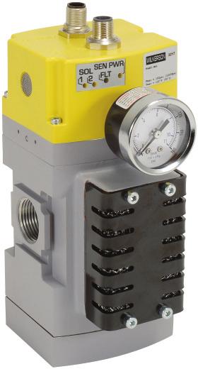
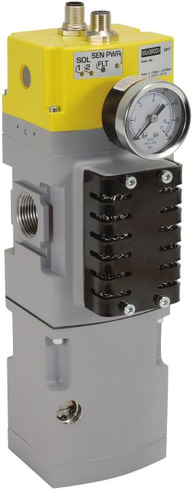
8 Integration Guide for Pressure Sensors & Gauges Shipment of Product The safety valve will be supplied with a plug inserted into the casting as shown. Gauge options ship with unit unassembled. If the G Dial Gauge is ordered, part# K4515N18160 will ship with the safety valve. If the D Digital Gauge (K4517N14160D) option is ordered, an adapter (part# 222P-4-2) is also provided to connect 1/8 port to 1/4 gauge. + (Not to scale)
9 Integration Guide for Pressure Sensors & Gauges Pressure Sensor Option The safety valve is available with option pressure sensor MPS-P34. The pressure sensor MPS-P34N-PCI is 1/8" NPT male with M8 Male electrical connection and mates directly to the valve.
. The red box highlights the optional soft start in the unit.")
10 Integration Guide for General Operation & LED Status Siemens General Operation Guide (Schematics) The Wilkerson E28/Q28 schematic shows patented cross flow technology. Solid state pressure sensors are used in this design (in place of mechanical switches). The red box highlights the optional soft start in the unit. General Operation Guide (Dimensions) Standard nominal flow rate is based on 6 bar input pressure with P = 1 bar


11 Integration Guide for General Operation & LED Status Siemens General Operation Guide (Wiring) The E28/Q28 valve is available with various wiring options for both the solenoid cable and the sensor cable. For example, the following model number is wired internally with the DB wiring option: Model Number: E2806DBN This means the valve in this example is wired with the D solenoid configuration and the B Sensor configuration. Use these diagrams to determine the proper pinouts for your valve.
12 Integration Guide for General Operation & LED Status Siemens General Operation Guide (Technical)
. The monitoring logic should automatically shut off power to both solenoids.")
13 Integration Guide for General Operation & LED Status Siemens General Operation Guide (LED Status Lights) FAULT (FLT): Flashing Red: Sensors are in different States. The E28/Q28 unit will automatically fail to a mechanical safe state (no downstream pressure). The monitoring logic should automatically shut off power to both solenoids. If FLT light is flashing and either or both solenoid lights are ON it indicates the monitoring logic is not properly detecting this fault. The E28/Q28 unit should be powered down and monitoring logic reviewed and re-tested before putting into operation again. If FLT light is flashing and both solenoid lights are OFF it indicates the unit has an internal malfunction and should be replaced before continuing operation. OFF: Sensors are in the same state no issue. Solenoid Power (SOL 1/2): Green : Power is properly applied to solenoid 1 and/or solenoid 2. OFF : No power is applied to the solenoids. Check connection from Solenoid M12 to output device Sensor Power (SEN PWR): Green : Power is properly applied to the sensors OFF : No power to the sensors. Check connection from Sensor M12 to input device
14 Integration Guide for Operation Operation & Monitoring Requirements The intent of this document is to provide guidance on how to operate and monitor the E28/Q28 valve for safe operation. A test procedure is also provided for verification and validation of the user s external safety control monitoring system. Valve Operation The E28/Q28 valve is a redundant safety exhaust (dump) valve. Its function is that of a 3/2, normally closed, single-solenoid valve. However, because the valve is redundant it has two operating solenoids that must be operated simultaneously in order to actuate the valve. Actuating the valve will supply pressure from port 1 (supply) to port 2 (outlet) and close port 3 (exhaust). De-actuating the valve will close port 1 (supply) and open port 2 (outlet) to port 3 (exhaust). De-actuation of the valve is accomplished by turning off both solenoids simultaneously. Valve Operation Faulted Condition In the event of a valve fault where one of the redundant valve components does not operate synchronously as commanded, the valve will perform its safety function which is to shut off supply and exhaust downstream pressure to atmosphere. Synchronous operation occurs when both sets of valve internals shift within 150 msec of each other. Failure of the valve to shift synchronously leads to a fault in the P33 valve. This could happen for a variety of reasons, such as: Defective piston seals Main valve elements experiencing a switching delay due to dirt, debris or resinous oil Insufficient electrical signals to valve solenoids; suitable voltage not available Receipt of signals at solenoids not synchronous Pilot valves experiencing a switching delay due to damaged components, dirt, debris or resinous oil Excessive water build-up in the valve
15 Integration Guide for Monitoring Logic Monitoring of the Valve The E28/Q28 valve is equipped with feedback pressure sensors that must be monitored by the user s external safety control monitoring system to detect any fault condition within the valve. Sensor feedback should always agree with the solenoid actuating signals. Detection of any valve fault should disable the safety control outputs to the valve solenoids and prevent any subsequent attempts to actuate the valve until a safety control system reset is performed. Refer to EN ISO for cat 3 vs cat 4 monitoring. Automatic RESET is not recommended by WILKERSON Actuation Fault Monitoring Actuation fault monitoring should check for valve actuation synchronicity. After the safety control system outputs provide simultaneous actuation signals to both solenoids, both sensor outputs should switch off within 150 msec of each other. Dependent upon which sensor switches off first, the following faults should be detected. 1. A side fault detection if sensor A does not switch off within 150 msec after sensor B switches off, this should be registered as a fault. 2. B side fault detection if sensor B does not switch off within 150 msec after sensor A switches off, this should be registered as a fault. De-Actuation Fault Monitoring De-Actuation fault monitoring should check for valve de-actuation synchronicity. After the safety control system simultaneously remove the actuation signals from both solenoids, both sensor outputs should switch on within 150 msec of each other. Dependent upon which sensor switches on first, the following faults should be detected. 1. A side fault detection - sensor A does not switch on within 150 msec after sensor B switches on, this should be registered as a fault. 2. B side fault detection if sensor B does not switch on within 150 msec after sensor A switches on, this should be registered as a fault.
16 Integration Guide for Validation Test Procedure for Valve Operation and External Monitoring Logic NOTE: This test procedure should only be performed with an E28/Q28 valve that is known to be functioning properly. If basic valve function is in question, please refer to Section 8 of the Product Operating Instructions for the Valve Test Procedure. Valve Operation 1. Energize solenoids A & B simultaneously. Valve is on, air pressure is supplied downstream from supply port 1 through outlet port 2, and exhaust port 3 is shut off. Sensors A & B are off. 2. De-energize solenoids A & B simultaneously. Valve is off, supply port 1 is blocked, and downstream air is exhausted from outlet port 2 through exhaust port 3. Sensors A & B are on. Test Procedure Actuation Fault Monitoring (with Fault Latching) NOTE: These test procedures required fault simulation. It will be necessary to induce faults electrically by disabling one solenoid or the other at different times, which may require special test cabling in order to complete the test procedure. Also, be aware that this would only be possible with solenoid wiring option A. See product data sheet. 3. Energize only solenoid A. This should result in a sensor A switching off while sensor B stays on. Your safety control monitoring system should detect this fault in the valve, where sensor A switches off and sensor B stays on more than 150 msec after sensor A switches off. This fault should trigger the safety outputs to switch off in order to de-energize both solenoids, A & B. The fault should be latched in by the safety control system logic until the system is reset. While the fault exists supply port 1 is blocked, and downstream air from outlet port 2 is open to exhaust port 3. Once the safety control system de-energizes the solenoids, sensors A and B should both be on. 4. Before attempting to reset the safety control system, attempt to energize both solenoids, A & B, simultaneously. Supply port 1 should remain blocked and downstream air from outlet port 2 should remain open to exhaust via exhaust port De-energize both solenoids A & B. 6. Reset the safety control system.
17 Integration Guide for Validation Test Procedure Actuation Fault Monitoring (with Fault Latching) Continued 7. Energize only solenoid B. This should result in sensor A staying on while sensor B switches off. Your safety control monitoring system should detect this fault in the valve, where sensor B switches off and sensor A stays on more than 150 msec after sensor A switches off. This fault should trigger the safety outputs to switch off in order to de-energize both solenoids A & B. The fault should be latched in by the safety control system logic until the system is reset. While the fault exists, supply port 1 is blocked, and downstream air from outlet port 2 is open to exhaust port 3. Once the safety control system de-energizes the solenoids, sensors A and B should both be on. 8. Before attempting to reset the safety control system, attempt to energize both solenoids, A & B, simultaneously. Supply port 1 should remain blocked and downstream air from outlet port 2 should remain open to exhaust via exhaust port De-energize both solenoids A & B. 10. Reset the safety control system. Test Procedure De-Actuation Fault Monitoring (with Fault Latching) NOTE: These test procedures required fault simulation. It will be necessary to induce faults electrically by disabling one solenoid or the other at different times, which may require special test cabling in order to complete the test procedure. Also, be aware that this would only be possible with solenoid wiring option A. See product data sheet. 11. Energize solenoids A & B, simultaneously. This switches the valve on and should result in air pressure being supplied downstream from supply port 1 through outlet port 2, and exhaust port 3 being shut off. Sensors A & B should both switch off. 12. De-energize only solenoid A. The safety control system should detect the fault in the valve where sensor A switches on and sensor B stays off more than 150 msec after sensor A switches on. This fault should trigger the safety outputs to switch off in order to de-energize both solenoids A and B. The fault should be latched in by the safety control system logic until the system is reset. While the fault exists supply port 1 is blocked and downstream air from outlet port 2 is open to exhaust port 3. Once the safety control system de-energizes the solenoids sensors A and B should be both on.
18 Integration Guide for Validation Test Procedure De-Actuation Fault Monitoring (with Fault Latching) Continued 13. Before attempting to reset the safety control system, attempt to energize both solenoids A and B simultaneously. Supply port 1 should remain blocked and downstream air from outlet port 2 should remain open to exhaust via exhaust port De-energize both solenoids A & B. 15. Reset the safety control system. 16. Energize both solenoids, A & B simultaneously. This switches the valve on and should result in air pressure being supplied downstream from supply port 1 through outlet port 2, and exhaust port 3 being shut off. Sensors A & B should be both switched off. 17. De-energize only solenoid B. The safety control system should detect the fault in the valve where sensor B switches on and sensor A stays off more than 150 msec after sensor B switches on. This fault should trigger the safety outputs to switch off in order to de-energize both solenoids, A & B. The fault should be latched in by the safety control system logic until the system is reset. While the fault exists supply port 1 is blocked, and downstream air from outlet port 2 is open to exhaust port 3. Once the safety control system de-energizes the solenoids, sensors A and B should both be on. 18. Before attempting to reset the safety control system, attempt to energize solenoids, A & B simultaneously. Supply port 1 should remain blocked and downstream air from outlet port 2 should remain open to exhaust via exhaust port De-energize both solenoids A & B. 20. Reset the safety control
19 Integration Guide for Validation Test Procedure for Loss of Supply Pressure While Actuated 1. Energize both solenoids, A & B, simultaneously. This switches the valve on and should result in air pressure being supplied downstream from supply port 1 through outlet port 2, and exhaust port 3 being shut off. Sensors A & B should both switch off. 2. Remove supply air from supply port 1. Sensors A & B should switch on. External monitoring should detect the fault in the valve where both solenoids are on, but both sensors are also switched on. This fault should trigger the safety outputs to switch off in order to de-energize both solenoids, A & B. The fault should be latched in by the safety control system logic until the system is reset. While the fault exists, supply port 1 is blocked, and downstream air from outlet port 2 is open to exhaust port 3. Sensors A and B should remain on. 3. Re-supply air to supply port 1. Supply port 1 is blocked and downstream air from outlet port 2 is open to exhaust via port 3. Sensors A & B should both be on. Re-supplying air while the fault is latched in the safety control system should not result in air being supplied from supply port 1 to outlet port Reset the safety control system.
20 Integration Guide for Monitoring Logic Monitoring of Supply Pressure Loss of Supply Pressure While Actuated The condition of loss of supply pressure while the valve is actuated must be detected by the safety control monitoring system. Loss of supply pressure while actuated should cause both sensors to switch on due to lack of pressure in both valves outlet port even though the valve is still energized. This fault can be detected when the solenoids are high, and one or both sensors go from low (sensing pressure) to high (not sensing pressure). No Supply Pressure Applied Before Actuation Monitoring of supply pressure may also be utilized if deemed beneficial for the application but is not required. If you choose to detect this condition it would require the addition of an upstream pressure switch or transducer. The condition of the pressure switch or transducer should be monitored to prevent actuation of the valve when supply pressure is insufficient. Safety System Reset Any detected fault in the valve system should cause the safety control system to deactuate the valve by removing power from both solenoids. A reset of the safety control system should only be possible after the valve sensors indicate that the valve is in the de-actuated state (both sensors switched on).
21 Integration Guide Safe Relay with Standard PLC Integration Guide (Safe Relay with Standard PLC) (for applications requiring Cat 3 PL d)


22 Integration Guide for Rockwell 440R-D22S2 Rockwell 440R-D22S2 Part Number: 440R-D22S2 Functional Safety Rating: Cat 4, PL e Uses terminals Customer will have colored wires Can be wired with a PLC for sensors monitoring Examples include with and without pin outs and valve schematic Generic Connection Example (from Rockwell Catalog): The DIS safety relay has two dual-channel inputs and four solid-state outputs. Two of the four solid-state outputs are designed to operate with high-capacitance loads. In addition, the DIS safety relay has SWS input and output. The DIS safety relay can be set for automatic or monitored manual reset by adjusting the switch on the front panel. The configuration switch also sets the AND/OR logic that is applied to the inputs.


23 Integration Guide for Rockwell 440R-D22S2 Rockwell 440R-D22S2 Wiring (Generic Wiring Examples from the Rockwell Catalog)
24 Integration Guide for Rockwell 440R-D22S2 Rockwell 440R-D22S2 Wiring Schematic with PLC to Interface to Safety Exhaust Valve This schematic shows an example of an e-stop circuit for reference only. M12 Pinouts for E28/Q28 With this schematic it is possible to achieve up to Cat 3 PL d if properly implemented.
25 Integration Guide for Rockwell 440R-D22S2 Rockwell 440R-D22S2 Program* External monitoring program a) sensor error : In2 <> In3 after discrepancy time at 150 ms b) feedback error : In2 = In3 = In0 after installation discrepancy time c) If error Reset Out 1 & Out 2 Reset error only after maintenance acknowledge Reset function d) IF No feedback error & In1 Out0 = pulse of 2 s *Programs provided in this integration guide are for reference only. These programs have not been certified or tested unless stated otherwise.


: The same schematic is used, but with 4 dual inputs for")
26 Integration Guide for Schmersal SRB-E-204ST Schmersal SRB-E-204ST Part Number: SRB-E-20*ST *=1 or 4 double inputs Functional Safety Rating: Cat 4, PL e Uses terminals Customer will have colored wires Can be wired with a PLC for sensor monitoring Examples include with and without pin outs and valve schematic Generic Connection Example for Schmersal SRB-E-201ST (from Schmersal Catalog): The same schematic is used, but with 4 dual inputs for P/N SRB-E-204ST
27 Integration Guide for Schmersal SRB-E-204ST Schmersal Wiring Schematic for SRB-E-2014ST with PLC to Interface to Safety Exhaust Valve This schematic shows an example of an e-stop circuit for reference only. M12 Pinouts for E28/Q28 With this schematic it is possible to achieve up to category 3 PL d if properly implemented.
28 Integration Guide for Schmersal SRB-E-204ST Schmersal - Program* External monitoring program a) sensor error : In2 <> In3 after discrepancy time at 150 ms b) feedback error : In2 = In3 = In0 after installation discrepancy time c) If error Reset Out 1 set error only after maintenance acknowledge Reset function d) IF No feedback error & In1 Out0 = pulse of 2 s *Programs provided in this integration guide are for reference only. These programs have not been certified or tested unless stated otherwise.
: A safety function describes the reaction of a machine/plant to the")

29 Integration Guide for Siemens Sirius 3SK1112 Siemens 3SK1112 Part Number: 3SK1112 Functional Safety Rating: Cat 4, PL e Uses terminals Customer will have colored wires Can be wired with a PLC for sensor monitoring Examples include with and without pin outs and valve schematic Safety Function Information (from Siemens Catalog): A safety function describes the reaction of a machine/plant to the occurrence of a specific event (e.g. opening of a protective door.) Execution of the safety function(s) is carried out by a safety-related control system. This usually comprises three subsystems, detecting, evaluating and reacting. Detecting (sensors): Used to detect a safety requirement, eg: Emergency stop or a sensor for monitoring a hazardous area (light array, laser scanner etc) is operated. Evaluating (safety relay): Detecting a safety requirement and safely initiating the reaction (eg. Switching off the safety related outputs). Monitoring the correct operation of sensors and actuators. Initiating a reaction upon detection of faults. For the 3SKI products described in this guide, this concerns evaluation units for safety functions. Reacting (actuators): Switching off the hazard by means of downstream actuators.
30 Integration Guide for Siemens Sirius 3SK1112 Generic Siemens Wiring Schematic for 3SK1112 (from Siemens Catalog)

31 Integration Guide for Siemens Sirius 3SK1112 Generic Siemens Wiring Schematic for 3SK1112 (from Siemens Catalog)

32 Integration Guide for Siemens Sirius 3SK1112 Siemens Wiring Schematic with Dual Output to Interface to Safety Exhaust Valve M12 Pinouts for E28/Q28 Siemens Wiring Schematic with One Safe Output to Interface to Safety Exhaust Valve M12 Pinouts for E28/Q28
33 Integration Guide for Siemens Sirius 3SK1112 Siemens Wiring Schematic for 3SK1112-1BB40 with PLC to Interface to Safety Exhaust Valve This schematic shows an example of an e-stop circuit for reference only. M12 Pinouts for E28/Q28 With this schematic it is possible to achieve up to category 3 PL d if properly implemented.
34 Integration Guide for Siemens Sirius 3SK1112 Siemens- Program* External monitoring program a) sensor error : In2 <> In3 after discrepancy time at 150 ms b) feedback error : In2 = In3 = In0 after installation discrepancy time c) If error Reset Out 1 set error only after maintenance acknowledge Reset function d) IF No feedback error & In1 Out0 = pulse of 2 s *Programs provided in this integration guide are for reference only. These programs have not been certified or tested unless stated otherwise.
35 Integration Guide Programmable Safe Relay Integration Guide (Programmable Safe Relay) (for applications requiring Cat 4 PL e)
: Dual-channel E-STOP and safety gate wiring, monitored start and feedback")
36 Integration Guide for Pilz PNOZ Pilz PNOZ Part Number: Pnoz m B0 Functional Safety Rating: Cat 4, PL e Uses terminals Customer will have colored wires Can be wired with and without test pulses on the sensors Examples include with and without pin outs and valve schematic Generic Connection Example (from Pilz Catalog): Dual-channel E-STOP and safety gate wiring, monitored start and feedback loop.

37 Integration Guide for Pilz PNOZ Pilz Wiring Schematic (without sensor test pulse) to Interface to Safety Exhaust Valve M12 Pinouts for E28/Q28 With this schematic it is possible to achieve up to category 4 PL e if properly implemented. Pilz Wiring Schematic (with sensor test pulse) to interface to Safety Exhaust Valve M12 Pinouts for E28/Q28 With this schematic it is possible to achieve up to category 4 PL e if properly implemented.

38 Integration Guide for Pilz PNOZ Pilz - Program* Contains pinouts; these can vary based on wiring ie feedback listed as I6 & I7, could be I4, I5, I6, or I7 *Programs provided in this integration guide are for reference only. These programs have not been certified or tested unless stated otherwise.

39 Integration Guide for Rockwell 440C-CR30 Rockwell 440C-CR30 Part Number: 440C-CR30-22BBB Functional Safety Rating: Cat 4, PL e Software configured safety relay 22 safety I/O with embedded serial port USB programming port 2 plug-in slots 24 V DC Generic Connection Example (from Rockwell Catalog):
40 Integration Guide for Rockwell 440C-CR30 Generic Rockwell Wiring Schematic for 440C-CR30 (from the Rockwell Catalog)

41 Integration Guide for Rockwell 440C-CR30 Rockwell Wiring Schematic (without sensor test pulse) to Interface to Safety Exhaust Valve This schematic shows an example of an e- stop circuit for reference only M12 Pinouts for E28/Q28 With this schematic it is possible to achieve up to category 4 PL e if properly implemented. Rockwell Wiring Schematic (with sensor test pulse) to Interface to Safety Exhaust Valve This schematic shows an example of an e-stop circuit for reference only M12 Pinouts for E28/Q28 With this schematic it is possible to achieve up to category 4 PL e if properly implemented.
42 Integration Guide for Rockwell 440C-CR30 Rockwell Wiring Schematic (without sensor test pulse) to Interface to Safety Exhaust Valve This schematic shows an example of an e-stop circuit for reference only. With this schematic it is possible to achieve up to category 4 PL e if properly implemented.
43 Integration Guide for Rockwell 440C-CR30 Rockwell - Program* External monitoring program a) IF I.5 = I.6 = I.4 THEN set O.18 = O.19 = 1 b) Sensor discrepancy error: I.5 <> I.6 (max. discrepancy time = 150 msec) c) Loss of pressure error: I.7 = I.8 = 0 AND O.18 = O.19=1 followed by I.7=I.8=O.18=O.19=1 d) IF sensor discrepancy error OR loss of pressure error THEN reset O.18 = O.19 =0 Errors must be reset only after maintenance acknowledgement *Programs provided in this integration guide are for reference only. These programs have not been certified or tested unless stated otherwise.
44 Integration Guide Safe PLC I/O Integration Guide (Safe PLC I/O) (for applications requiring Cat 4 PL e)
45 Integration Guide for Rockwell 1732ES-IB8XOB8 Rockwell 1732ES-IBX0B8 Part Number: 1732ES-IB8X0B8 Functional Safety Rating: Cat 4, PL e Uses M12 Direct M12 cable Central or IO modules Dual output
46 Integration Guide for Rockwell 1732ES-IB8XOB8 Generic Rockwell 1732ES-IB8XOB8 Wiring (from Rockwell Catalog)

47 Integration Guide for Rockwell 1732ES-IB8XOB8 Rockwell 1732ES-IB8X0B8 Wiring Schematic (from Rockwell Catalog) to Interface to Safety Exhaust Valve I0/1 O0/1 M12 Pinouts for E28/Q28 With this schematic it is possible to achieve up to Cat 4 PL e if properly implemented.
48 Integration Guide for Rockwell 1732ES-IB8XOB8 Rockwell - Program* External monitoring program a) IF I.0 = I.1 = 1 THEN set O.0 = O.1 = 1 when commanded b) Sensor discrepancy error: I.0 <> I.1 (max. discrepancy time = 150 msec) c) Loss of pressure error: I.0 = I.1 = 0 AND O.0 = O.1=1 followed by I.0=I.1=O.0=O.1=1 d) IF sensor discrepancy error OR loss of pressure error THEN reset O.0 = O.1=0 Errors must be reset only after maintenance acknowledgement *Programs provided in this integration guide are for reference only. These programs have not been certified or tested unless stated otherwise.

49 Integration Guide for Rockwell 1732ES-IB8XOBV4 Rockwell 1732ES-IB8XOBV4 Part Number: 1732ES-IB9X0BV4 Functional Safety Rating: Cat 4, PL e A B C D E F G H Uses M12 Direct M12 cable Central or IO modules Safe output
50 Integration Guide for Rockwell 1732ES-IB8XOBV4 Generic Rockwell 1732ES-IB8XOBV4 Wiring (from Rockwell Catalog)
 to")

51 Integration Guide for Rockwell 1732ES-IB8XOBV4 Rockwell 1732ES-IB8X0BV4 Wiring Schematic (from Rockwell Catalog) to Interface to Safety Exhaust Valve I0/1 O0/1 M12 Pinouts for E28/Q28 With this schematic it is possible to achieve up to Cat 4 PL e if properly implemented.
52 Integration Guide for Rockwell 1732ES-IB8XOBV4 Rockwell - Program* External monitoring program a) IF I.0 = I.1 = 1 THEN set O.0 = O.1 = 1 when commanded b) Sensor discrepancy error: I.0 <> I.1 (max. discrepancy time = 150 msec) c) Loss of pressure error: I.0 = I.1 = 0 AND O.0 = O.1=1 followed by I.0=I.1=O.0=O.1=1 d) IF sensor discrepancy error OR loss of pressure error THEN reset O.0 = O.1=0 Errors must be reset only after maintenance acknowledgement *Programs provided in this integration guide are for reference only. These programs have not been certified or tested unless stated otherwise.
53 Integration Guide for Siemens ET200PRO Safe Siemens ET200PRO Safe Part Number: ET200PRO Safe Functional Safety Rating: Cat 4, PL e Uses M12 Direct M12 Cable Central or IO modules Examples include with and without pin outs and valve schematic Generic Connection Example (from Siemens Catalog):
54 Integration Guide for Siemens ET200PRO Safe Siemens Wiring Schematic for ET200PRO Safe to Interface to Safety Exhaust Valve I0/1 O0/1 M12 Pinouts for E28/Q28 With this schematic it is possible to achieve up to category 4 PL e if properly implemented.
55 Integration Guide for Siemens ET200PRO Safe Siemens - Program* External monitoring program a) sensor error : I.0 <> I.1 Adjust discrepancy time at 150 ms c) feedback error : I.0 = I.1 = Out 0 Adjust discrepancy time d) IF feedback or sensor error THEN reset Out 0 Errors must be reset only after maintenance acknowledgement *Programs provided in this integration guide are for reference only. These programs have not been certified or tested unless stated otherwise.


56 Integration Guide for Siemens Simatic S7 Siemens Simatic S7 Part Number: Simatic S7 Functional Safety Rating: Cat 4, PL e Uses Terminals Customer will have colored wires Central or IO modules Examples include with and without pin outs and valve schematic


57 Integration Guide for Siemens Simatic S7 Generic Siemens Wiring Examples for S7 1200F (from Siemens Catalog):


58 Integration Guide for Siemens Simatic S7 Siemens Wiring Schematic Safe Output without Sensor Test Pulse Version AC to Interface to Safety Exhaust Valve M12 Pinouts for E28/Q28 With this schematic it is possible to achieve up to category 4 PL e if properly implemented. Siemens Wiring Schematic Safe Output without Sensor Test Pulse Version CC to Interface to Safety Exhaust Valve M12 Pinouts for E28/Q28 With this schematic it is possible to achieve up to category 4 PL e if properly implemented.


59 Integration Guide for Siemens Simatic S7 Siemens Wiring Schematic Safe Output with Sensor Test Pulse to Interface to Safety Exhaust Valve M12 Pinouts for E28/Q28 With this schematic it is possible to achieve up to category 4 PL e if properly implemented.
60 Integration Guide for Siemens Simatic S7 Siemens - Program* External monitoring program a) sensor error : Dia.0 <> Dib.0 Adjust discrepancy time at 150 ms b) feedback error : Dia.0 = Dib.0 = Out 0 Adjust discrepancy time c) IF feedback or sensor error THEN reset Out 0 Errors must be reset only after maintenance acknowledgement *Programs provided in this integration guide are for reference only. These programs have not been certified or tested unless stated otherwise.


61 Integration Guide for Turck TBPN-L1-FDIO1-2IOL Turck TBPN-L1-FDIO1-2IOL Functional Safety Rating: Cat 4, PL e Uses M12 connections Direct M12 cables Central or IO modules Generic Connection Example (from Turck Catalog):

62 Integration Guide for Turck TBPN-L1-FDIO1-2IOL Generic Turck Wiring Schematic (from Turck Catalog): Safety Integrity Level/Performance Level/Category The devices are rated for applications up to: SIL3 according to EN/IEC/ and EN/EC Category 4 / PL e according to EN ISO

63 Integration Guide for Turck TBPN-L1-FDIO1-2IOL Turck Wiring Schematic TBPN-L1-FDIO1-2IOL to Interface to Safety Exhaust Valve M12 Pinouts for E28/Q28 With this schematic it is possible to achieve up to category 4 PL e if properly implemented.
64 Integration Guide for Turck TBPN-L1-FDIO1-2IOL Turck TBPN - Program* External monitoring program a) sensor error : I.0 <> I.1 Adjust discrepancy time at 150 ms b) feedback error : I.0 = I.1 = Out 4 Adjust discrepancy time c) IF feedback or sensor error THEN reset Out 4 Errors must be reset only after maintenance acknowledgement *Programs provided in this integration guide are for reference only. These programs have not been certified or tested unless stated otherwise.
CONTROLS M35 SERIES SAFETY EXHAUST DOUBLE VALVES INTEGRATION GUIDE.
 CONTROLS M SERIES SFETY EXHUST DOUBLE VLVES INTEGRTION GUIDE www.rosscontrols.com M Series Integration Guide Table of Contents Integration Guide M Safety Exhaust Valve Page General Information Introduction
P33T Series Redundant Safety Exhaust Valve ENGINEERING YOUR SUCCESS.
 aerospace climate control electromechanical filtration fluid & gas handling hydraulics pneumatics process control sealing & shielding P33T Series Redundant Safety Exhaust Valve Catalogue PDE675TCUK October
P33T Series Redundant Safety Exhaust Valve ENGINEERING YOUR SUCCESS. Bulletin 0700-B13.
 aerospace climate control electromechanical filtration fluid & gas handling hydraulics pneumatics process control sealing & shielding P33T Series Redundant Safety Exhaust Valve Bulletin 0700-B3 ENGINEERING
Achieving Required Safety Levels Using a Pneumatic Safety Exhaust Valve
 EMBARGO DATE OCTOBER 16, 2017 Parker Hannifin Corporation Pneumatic Division 8676 E. M89 P.O. Box 901 Richland, Michigan 49083 USA www.parker.com/pneumatics Achieving Required Safety Levels Using a Pneumatic
Redundant Control System
 Redundant Control System Safety instrumented system applications up to SIL 3 Process reliability Process valve diagnostics COMPLETE FUNCTIONAL SAFETY WITH ENHANCED RELIABILITY The Redundant Control System
4 Redundant Control System
 4 Redundant Control System Introducing the all NEW RCS Configurator Safety Instrumented Systems Process Reliability Process Valve Diagnostics COMPLETE FUNCTIONAL SAFETY WITH ENHANCED RELIABILITY The Redundant
TECHNICAL PAPER 1002 FT. WORTH, TEXAS REPORT X ORDER
 I. REFERENCE: 1 30 [1] Snow Engineering Co. Drawing 80504 Sheet 21, Hydraulic Schematic [2] Snow Engineering Co. Drawing 60445, Sheet 21 Control Logic Flow Chart [3] Snow Engineering Co. Drawing 80577,
Product Guide: Series III Pump Control Board Set (RoHS)
") revised 04/08/10 Description: The Series III Pump Control Board Set provides motor drive and pump control for a wide assortment of pumps from Scientific Systems, Inc. The assembly consists of two circuit
revised 04/08/10 Description: The Series III Pump Control Board Set provides motor drive and pump control for a wide assortment of pumps from Scientific Systems, Inc. The assembly consists of two circuit
FUNCTIONAL SAFETY SOLUTIONS in Solenoid Valves
 FUNCTIONAL SAFETY SOLUTIONS in Solenoid Valves Safety is reality and is part of our daily business. The same applies to ASCO; it is reality and part of your safety. You can rely on our focus on reliable
NHP SAFETY REFERENCE GUIDE
 NHP SAFETY REFERENCE GUIDE GSR SAFETY FUNCTION DOCUMENTS Door Monitoring Trojan 5 Interlock Switch, Guardmaster Safety Relay, PowerFlex 525 Drive with Safe Torque-off Table of Contents: Introduction 6-122
Selecting & Integrating Safety Exhaust Valves White Paper
 Selecting & Integrating Exhaust Valves White Paper Selecting and Integrating Exhaust Valves Linda Caron Global Product Manager, Factory Automation Parker Hannifin Corporation Today, exhaust valves are
Process switches and PLC circuits
 Process switches and PLC circuits This worksheet and all related files are licensed under the Creative Commons Attribution License, version 1.0. To view a copy of this license, visit http://creativecommons.org/licenses/by/1.0/,
MODEL 422 Submersible Pump Controller
 MODEL 422 Submersible Pump Controller Monitors True Motor Power (volts x current x power factor) Detects Motor Overload or Underload Operates on 120 or 240VAC, Single-phase or 3-phase Built-in Trip and
CONTROLS ROSS SAFETY-RELATED PRODUCTS
 CONTROLS ROSS SAETY-RELATED PRODUCTS Energy Isolation Lockout and Lockout with Soft-Start Valves Safety Exhaust Control Reliable Energy Isolation Double Valves Safety Exhaust & Safety Exhaust/Energy Isolation
APPLICATION NOTES DELOMATIC
 APPLICATION NOTES DELOMATIC 400 Safety system Document no.: 4189340885B SW version 1.33.3 or later Table of contents 1. ABOUT THIS DOCUMENT... 3 GENERAL PURPOSE... 3 INTENDED USERS... 3 CONTENTS/OVERALL
Remote Process Actuation Control System AirLINE - Rockwell 1734 Point I/O System
 Remote Process Actuation Control System AirLINE - Rockwell 1734 Type 8644 can be combined with... Fully compatible with Rockwell 1734 Point I/O System Combination of Fieldbus, pilot valves and I/O modules
S-Series. Solenoid Valves
 S-Series Company Profile Experience and proven results have made BERMAD synonymous with water and other fluid control and management. Cutting-edge technology is one of the reasons BERMAD has retained its
BERMAD Irrigation. Solenoid Valves S - Series. Water Control Solutions
 Solenoid Valves Water Control Solutions Company Profile Experience and proven results have made BERMAD synonymous with water and other fluid control and management. Cutting-edge technology is one of the
Remote Process Actuation Control System AirLINE - Siemens ET 200S
 Remote Process Actuation Control System AirLINE - Siemens ET 200S Type 8644 can be combined with... Fully compatible with Siemens ET 200S Combination of Fieldbus, pilot valves and I/O modules High flexibility
UNI EN ISO EN
 Airplus Safeline eneral Upon implementation of the AIRPLUS T series, air-treatment units, PNEUMAX develops a supply and discharge valve, with an electropneumatic control and spring-return, fitted with
CONTROLS ROSS SAFETY-RELATED PRODUCTS
 CONTROLS ROSS SAETY-RELATED PRODUCTS Lockout & Exhaust and Soft-Start Valves Sensing Valves Double Valves for Control Reliable Energy Isolation Pilot Operated Check Valves Double Valves for Cylinder Return
Connection of F-DQ to F-DI of SINAMICS
 FAQ 01/2017 Connection of F-DQ to F-DI of SINAMICS SINAMICS S120; SIMOTION D https://support.industry.siemens.com/cs/ww/en/view/39700013 This entry is from the Siemens Industry Online Support. The general
What you Need to Know About Safety Exhaust Valves White Paper
 What you Need to Know About Exhaust Valves White Paper What you Need to Know about Exhaust Valves Linda Caron Global Product Manager, Factory Automation Parker Hannifin Corporation Hazards posed by pneumatic
Safeguarding Applications and Wiring Diagrams Cat 1 Stop with Guardlocking Interlock and Proximity Sensors TLSZR-GD2, 872C, GLP, PowerFlex 45
 Cat with Guardlocking Interlock and TLSZ-GD, C,, PowerFlex 5 + VDC eset & Lock PowerFlex 5 LL L Brown ed Yellow Green Grey Pink White Blue TLSZ-GD D-FAC- X X 5 S5 S Y 6 -GLSP S S L5 5 A P P AX L Gnd S
HARDWIRE VS. WIRELESS FAILSAFE CONTROL SYSTEM. The answer is No.
 HARDWIRE VS. WIRELESS FAILSAFE CONTROL SYSTEM In today s industrial automation world, the debate continues Is wire more reliable then wireless? The answer is No. In any industrial control environment,
Control Reliable Double Valves with Total Dynamic Monitoring & Complete Memory
 Control Reliable Double Valves Safety Exhaust (Dump) DM Series D Self Monitored - Clutch/rake Control asic Size,,, and 0 Dynamic Monitoring With Complete Memory: Memory, monitoring, and air flow control
ROSS CONTROLS. Double Valves for Control Reliable Energy Isolation.
 ROSS CONTROLS Double Valves for Control Reliable Energy Isolation DM and DM Series CONTROL RELILE DOULE VLVES DM SERIES KEY ETURES Rapid response time to minimize stopping time Status Indicator switch
Safety Interlock Switches
 Safety Interlock Switches ATK ATK Safety Key Selector Switch Key-type selector switch with direct opening mechanism Selector Switch for secure equipment activation during maintenance 0 types of exclusive
Explanation 1 Input External Switch 2 Input Hipot Safety Switch
 on the 1100H+ The 1100H+ has capability, which allows you to set up the tester to control external devices with tester functions. You can also use an input on the tester to start a test. For example, the
Safety Control HR1S-AC. Safety Relay HR1S-AC
 HRS-AC Safety Relay HRS-AC Key features: NC or 2NC safety input type, such as E-Stops or Interlock Switches EN ISO 3849- PLe, Safety Cat 3 compliant, and EN 6206 SIL 3 Fault diagnosis function with dual
Welcome to the presentation about safety functions of ACS880 functional safety, FSO- 12 Safety functions module.
 Welcome to the presentation about safety functions of ACS880 functional safety, FSO- 12 Safety functions module. 1 Here is a list of the FSO-12 supported safety functions and example applications they
6.2. Conveyor Sensor Systems. 200 Series Zero Pressure Accumulation. 200 Series Zero Pressure Accumulation
 .2 Conveyor Systems Contents Description Product Overview...................... Product Selection Basic and Progressive Logic s..... Standard s.................... Accessories...........................
ACCESSORIES FOR AIR VALVES & AIR SYSTEMS
 ACCESSORIES FOR AIR VALVES & AIR SYSTEMS BULLETIN ACC-2000R AIR VALVES FOR INDUSTRY SINCE 1949 ISO 9001 CERTIFIED FOOT GUARDS Page 8 QUICK EXHAUST & ELECTRIC QUICK EXHAUST VALVES Pages 6 & 7 SHUTTLE VALVES
AIRPLANE OPERATIONS MANUAL SECTION 2-15
 SECTION 2-15 TABLE OF CONTENTS Block General... 2-15-05..01 Bleed Air Thermal Anti-Icing System... 2-15-10..01 Wing, Stabilizer and Engine Anti-icing Valves Operational Logic... 2-15-10..04 EICAS Messages...
SECTION G2: CABLE PROCESSOR MODULE MAINTENANCE
 SECTION G2: CABLE PROCESSOR MODULE MAINTENANCE Cable Processor Module overview WARNING! When tipping the Cable Processor Module back, (after removing the toggle arm pin), use extreme caution not to drop
Safety Sensor CSS 180 Product Information
 Safety Sensor CSS 180 Product Information Safety Sensor CSS 180 CSS180CSS 180 PDF-M / EN 60947-5-3 EN 954-1 Control Category 4 IEC 61508, suitable for use in SIL 3 applications BG Type-Certification in
ROSS CONTROLS. Double Valves for Control Reliable Energy Isolation.
 ROSS CONTROLS Double Valves for Control Reliable Energy Isolation DM and DM Series CONTROL RELILE DOULE VLVES DM SERIES KEY ETURES Rapid response time to minimize stopping time Status Indicator switch
3 (R) 1 (P) 5 (S) Port size 1 (P) 2 (A) 3 (R) 4 (B) 5 (S)
 1 (P) 5 (S) Port size 1 (P) 2 (A) 3 (R) 4 (B) 5 (S)") XSz 8V & XSz 0V 5/ directional control valve with dynamic monitoring For mechanical presses and other safety applications G/4, G/, /4 NPT & / NPT Inherently fail-safe without residual pressure Dynamic
XSz 8V & XSz 0V 5/ directional control valve with dynamic monitoring For mechanical presses and other safety applications G/4, G/, /4 NPT & / NPT Inherently fail-safe without residual pressure Dynamic
Solenoid interlock AZM 200 The non-contact interlock.
 Solenoid interlock AZM 200 The non-contact interlock. Solenoid interlock AZM 200 The non-contact Solenoid interlocks demand accurate alignment of actuator and device. This requirement is met on new machinery.
How to Design a Genset Fuel System With Gen Evo (Franklin) ATG
 ATG") ESS.HT.612 How to Design a Genset Fuel System With Gen Evo (Franklin) ATG GENERAL The GenEvo fuel system is a comprehensive fuel manager for reliable generator fuel supply. The Franklin Fuelling EVO 550
ESS.HT.612 How to Design a Genset Fuel System With Gen Evo (Franklin) ATG GENERAL The GenEvo fuel system is a comprehensive fuel manager for reliable generator fuel supply. The Franklin Fuelling EVO 550
Updated: October 2012
 T: (630) 794-5100 EMERGENCY POWER FUEL SYSTEMS Earthsafe Systems, Inc. 7320 S. Madison Willowbrook, IL 60527 F: (630) 794-5106 info@earthsafe.com www.earthsafe.com Updated: October 2012 The information
Product Information ROSS CONTROLS
 Product Information Safe Cylinder Return Double s CrossMirror ROSS CONTROLS with Dedicated Reset Solenoid Pilot Controlled Safe Cylinder Return Port Size Basic Size Status Indicator Pressure Switch without
MODEL 520 REMOTE START ENGINE MANAGEMENT SYSTEM
 MODEL 520 REMOTE START ENGINE MANAGEMENT SYSTEM DSE 520 ISSUE 4 4/4/02 MR 1 TABLE OF CONTENTS Section Page INTRODUCTION... 4 CLARIFICATION OF NOTATION USED WITHIN THIS PUBLICATION.... 4 1. OPERATION...
NHP SAFETY REFERENCE GUIDE
 4 NHP SAFETY REFERENCE GUIDE CONTENTS SAFETY TECHNOLOGY Risk Reduction Options Permanent Fixed Guard 4-02 Interlocked Guard: 4-03 Limit Switches 4-08 Presence Sensing Technology 4-09 Safety Laser Scanners
APPLICATION NOTE Application Note for Torque Down Capper Application
 Application Note for Torque Down Capper Application 1 Application Note for Torque Down Capper using ASDA-A2 servo Contents Application Note for Capper Axis with Reject Queue using ASDA-A2 servo... 2 1
Installation, Operation, and Maintenance Manual CEMLINE CORPORATION
 $5.00 Installation, Operation, and Maintenance Manual CEMLINE CORPORATION CEM-TROL II Solid State Control Module and Electronic Control Valves P. O. Box 55, Cheswick, PA, 15024 Phone: (724) 274-5430 FAX
Generator Start Control Module
 Generator Start Control Module Part# GSCM-mini-i ATKINSON ELECTRONICS, INC. 14 West Vine Street Murray, Utah 84107 Contact cbdsales@atkinsonel.com for the proper hookup diagram. Please include the generator
FLOOD PROTECTION SHUT DOWN VALVE (3 and smaller)
") FLOOD PROTECTION SHUT DOWN VALVE ( and smaller) 01/10 2 6 To Floor Drain L X JB11 4 FS99 5 Installed upstream of Reduced Zone Backflow Preventer. Normally Open Valve - Closes when discharge from RPZ Relief
FLOOD PROTECTION SHUT DOWN VALVE ( and smaller) 01/10 2 6 To Floor Drain L X JB11 4 FS99 5 Installed upstream of Reduced Zone Backflow Preventer. Normally Open Valve - Closes when discharge from RPZ Relief
This specification describes the minimum requirements for a hoist maintenance safeguard (HMS) system for mine hoists.
 system for mine hoists.") /2.0 PURPOSE This specification describes the minimum requirements for a hoist maintenance safeguard (HMS) system for mine hoists. The HMS system is a means of preventing hoist operation or movement to
/2.0 PURPOSE This specification describes the minimum requirements for a hoist maintenance safeguard (HMS) system for mine hoists. The HMS system is a means of preventing hoist operation or movement to
Installation guidelines. The system comprises of two basic circuits. These are:
 Installation guidelines Introduction The FTi High DP Shut Down system has been designed to allow simple and fast installation on to vehicles incorporating PLC and non-plc differential pressure monitoring
Paddle-wheel flow controller with optical principle for On/Off control
 Paddle-wheel flow controller with optical principle for On/Off control Type 8039 can be combined with... Indication, monitoring, transmitting and On/Off control in one device. Programmable s (transistor
BOX A3 TEST REL. DATE R.T. Check and Approval
 BOX A3 TEST 3 20-07-2012 REL. DATE R.T. Check and Approval INDEX 1 - FOREWORD......Page 3 2 - BOX A3 TEST FOR HYDRAULIC LIFTS...Page 3 2.1 GENERAL OPERATION...Page 3 2.2 HOW THE CHECK OF THE VALVE HYDRAULIC
INSTRUCTION MANUAL INSTALLATION, OPERATION, AND MAINTENANCE ACTUATOR MANIFOLD
 INSTRUCTION MANUAL INSTALLATION, OPERATION, AND MAINTENANCE B-3724M ACTUATOR MANIFOLD MIDLAND MANUFACTURING CORP. 7733 Gross Point Road Skokie, Illinois 60077 Phone (847) 677-0333 FAX (847) 677-0138 WEBSITE
Axpert-CSS AMTECH DRIVES Axpert-CSS Amtech
 The Axpert-CSS is a range of Combination Soft Starter panels offered by AMTECH DRIVES. We also offer the module unit as an individual product, named as Axpert-Opti torque Soft Starter. This is only the
HIGH POWER SOLENOID DRIVER 1
 Elactis SA Switzerland Phone : Fax : E-mail : Web : +41 22 364 65 85 +41 22 364 65 87 info@elactis.com http://www.elactis.com HIGH POWER SOLENOID DRIVER 1 ADRV1012K 1 This datasheet is a preliminary description.
Electronic Limit Switch Type
 Electronic Limit Switch Type 3738-20 with optional solenoid valve for on/off rotary actuators Application Electronic limit switch for on/off applications to indicate the end position of rotary actuators.
Digital III Fueling Vehicle Control System
 SM64335-2 April 2005 Aerospace Group Conveyance Systems Division Carter Brand Ground Fueling Equipment Applicable additional manuals: SM64335-1 Setup & Calibration User s Manual Digital III Fueling Vehicle
Soft Start-up Valve. AV2000/3000/4000/5000 Series
 Soft Start-up Valve V000/000/000/000 Series [Option] C- R- W- C R - W - Start-up valve for low speed air supply to gradually raise initial pressure in an air system and for quick exhaust by cutting off
Palletized Fixture Accessories
 Frequently Asked Questions Some questions about pallet and tombstone clamping systems are common to both novices and experienced users. The answers to the following questions may help you better understand
Continuing Education Course #206 Introduction to Designing Machine Control Systems Part 2
 1 of 5 Continuing Education Course #206 Introduction to Designing Machine Control Systems Part 2 1. Continuing to answer the following questions indicates that you understands that the presented material
Product Information. Safety Exhaust ROSS CONTROLS
 Product Information Safety Exhaust Double Valves M DM2 Series C ROSS CONTROLS Control Reliable Double Valves with Dynamic Monitoring and Memory Safety Exhaust (Dump) M DM 2 Series C F2 3/2 Double Valves
Heavy-Duty Safety Interlock Switch with Guard Door Locking
 C R US Conforms to EN1088, EN60947--1, EN292, EN60204-1 UL and C-UL listed TL8018- Heavy-Duty Safety Interlock Switch with uard Door Locking High locking force of,00 N (1,236 lb.) locks guard door shut
Product Information. Safety Exhaust ROSS CONTROLS
 Product Information Safety Exhaust Double Valves DM Series E ROSS CONTROLS Control Reliable Double Valves with Dynamic Monitoring and Memory Safety Exhaust (Dump) DM Series E Dynamic Monitoring with Memory:
All From One Source Hydraulic Closed Loop Control Systems for Gas and Steam Turbines
 All From One Source Hydraulic Closed Loop Control Systems for Gas and Steam Turbines 1 Introduction All From One Source Hydraulic Closed Loop Control Systems for Gas and Steam Turbines ensuring maximum
ACSI MODEL 1406BB-04-AO POWER SUPPLY INSTALLATION INSTRUCTIONS
 II 1400-10 ACSI MODEL 1406BB-04-AO POWER SUPPLY INSTALLATION INSTRUCTIONS Features: Up to 1.95 Amps Load Capacity Class 2 Rated Outputs Overload, Over Voltage, and Short Circuit Protection Standby Battery
Festo Modular Production System (MPS)
") ELEC E8114 Manufacturing Automation Systems Modelling Festo Modular Production System (MPS) Figure 1 Distribution station (left) and testing station (right) 1 Introduction The purpose of this document
ELEC E8114 Manufacturing Automation Systems Modelling Festo Modular Production System (MPS) Figure 1 Distribution station (left) and testing station (right) 1 Introduction The purpose of this document
AUTOMATION AND CONTROL TRADE 19 TAR SANDS
 AUTOMATION AND CONTROL TRADE 19 TAR SANDS Page 1 1.1.1 - General With this challenge, we will assess your: a) ability to analyze technical data. b) quality of wiring. c) capacity to implement an automatic
Generator Start Control Module
 Generator Start Control Module Part# GSCM-mini-o ATKINSON ELECTRONICS, INC. 14 West Vine Street Murray, Utah 84107 Contact cbdsales@atkinsonel.com for the proper hookup diagram. Please include the generator
Safety Application Note
 Safety Application Note Safety Application Note Rockwell Automation A Modular Safety System Design Concept Gobal E-Stop with Local Machine Guarding This application note shows a modular safety design concept
Fabrication and Automation of Solvent less Packaging Machine
 Fabrication and Automation of Solvent less Packaging Machine Masood Nazir*, Prof Rashmi Ranjan Das# * M.tech Student at School of Electrical Engineering, VIT University Vellore, Tamilnadu-632014 India
FT-10 Network Digital I/O Module Kits and
 Instruction Sheet 10-2004 FT-10 Network Digital I/O Module Kits 541 0771 and 541 0772 PURPOSE OF KIT The Digital I/O Module (DIM) makes provisions for a group of relay contact outputs and discrete inputs
LEAD FREE * LFF113RFP Flood Protection Shut Down Valve
 Technical Bulletin TB-ACV-LFF11RFP LEAD FREE * LFF11RFP Flood Protection Shut Down Valve Installed upstream of Reduced Zone Backflow Preventer. Normally Open Valve - Closes when continuous discharge from
ME 360 Test #3 Spring 08 5/5/08. Closed book, closed notes portion of test. Total of 25 out of 100 points for questions #1 to #6.
 ME 360 Test #3 Spring 08 5/5/08 Closed book, closed notes portion of test. Total of 25 out of 100 points for questions #1 to #6. 1) [10] Mark the following true (T) or false (F) questions a) Pressure relief
Device Description User Manual Logix MD+ Positioners with HART
 Device Description User Manual Logix MD+ Positioners with HART CONTENTS DD MENU CHART... 3 GENERAL INFORMATION... 6 INTRODUCTION... 6 QUALIFIED PERSONNEL... 6 USING THIS DOCUMENT... 6 TERMS CONCERNING
Induction Power Supplies
 Induction Power Supplies 7.5kW; 135 400kHz 480V version (Integral Heat Station) User s Guide Model 7.5-135/400-3-480 SMD Control Brds Rev. D 5/08 Table of Contents 1. Specifications and features...3 2.
Application Note. First trip test. A circuit breaker spends most of its lifetime conducting current without any
 Application Note First trip test A circuit breaker spends most of its lifetime conducting current without any operation. Once the protective relay detects a problem, the breaker that was idle for maybe
FLUID POWER FLUID POWER EQUIPMENT TUTORIAL PNEUMATIC CIRCUTS. This work covers part of outcome 3 of the Edexcel standard module:
 FLUID POWER FLUID POWER EQUIPMENT TUTORIAL PNEUMATIC CIRCUTS This work covers part of outcome 3 of the Edexcel standard module: UNIT 21746P APPLIED PNEUMATICS AND HYDRAULICS The material needed for outcome
Lease Automatic Custody Transfer
 Lease Automatic Custody Transfer Angus Manufactured LACT Units Updated 19-Dec-01, Slide 2 LACT Unit Requirements Are used for the automatic unattended measurement of crude oil. Accurately measure the quantity
Type Electronic Limit Switch
 Type 3738-20 Electronic Limit Switch With optional solenoid valve Application Electronic limit switch for on/off applications to indicate the end position. Optionally with integrated solenoid valve. Special
Compatibility of STPA with GM System Safety Engineering Process. Padma Sundaram Dave Hartfelder
 Compatibility of STPA with GM System Safety Engineering Process Padma Sundaram Dave Hartfelder Table of Contents Introduction GM System Safety Engineering Process Overview Experience with STPA Evaluation
Main Steam Isolation Valves (MSIV) in Nuclear Power Plants with PWR
 in Nuclear Power Plants with PWR") Main Steam Isolation Valves (MSIV) in Nuclear Power Plants with PWR FD2 1 E 02/2000 1 Introduction As isolating valve in the main steam line of nuclear power stations different designs are known. Beside
Main Steam Isolation Valves (MSIV) in Nuclear Power Plants with PWR FD2 1 E 02/2000 1 Introduction As isolating valve in the main steam line of nuclear power stations different designs are known. Beside
QS 100 LSM Power Management
 990000717 Revision A Table of Contents Revision History...2 Overview...3 Soft Start not complete fault...3 Under voltage fault...4 Under voltage warning limit...5 Over voltage maximum limit...5 Over voltage
Direct Communication Module
 Installation Instructions Direct Communication Module (Catalog Number 1747-DCM) Inside...................................... page For More Information.............................. 3 Hazardous Location
Technical data. Standards: IEC/EN , EN ISO , IEC 61508, IEC
 AZM 00,,,,, M0x1, 0 1, AZM 00➀-T-➁➂ 0 1 Solenoid interlock (Solenoid interlock monitoring) Thermoplastic enclosure Sensor technology permits an offset of ± mm between actuator and interlock Intelligent
NEW YORK AIR BRAKE CORPORATION
 NEW YORK AIR BRAKE CORPORATION A KNORR BRAKE COMPANY 748 Starbuck Avenue, Watertown, New York 13601 C.W. 307 COMPONENT WRITE-UP OF CCB-26 LOCOMOTIVE BRAKE SYSTEM ISSUE NO. 1 C.W. 307 GENERAL The CCB-26
Solenoid Valve Output Module IC693MDL760 Product Description
 GFK-A November 000 Solenoid Valve Output Module ICMDL0 Product Description Description This ICMDL0 output module provides eleven pneumatic outputs and five VDC sourcing outputs. For each pneumatic output,
Safe Cylinder Control and Stop and Load Holding Valves ROSS CONTROLS
 Safe Cylinder Control and Stop and Valves ROSS CONTROLS SAE CYLINDER CONTROL AND STOP CrossCheck TM DOUBLE VALVES, CC4 SERIES KEY EATURES Closed Center valve function Redundant control with position feedback
Installation & Instruction Manual for PCS-2000 Proofer Control System
 June 2001 Installation & Instruction Manual for PCS-2000 Proofer Control System W. H. Cooke & Co., Inc. 6868 York Rd. Hanover, PA 17331 Phone: 1-800-772-5151 www.whcooke.com Table of Contents Introduction....................................
Frame size R2, IP20 / NEMA 1
 Dimension drawings 395 Frame size R2, IP20 / NEMA 1 1) 1) Extension modules add 26 mm (1.02 in) to the depth measure. 3AUA0000067783-A Frame size R2, IP20 / NEMA 1 396 Dimension drawings Frame size R3,
W A L C H E M. PosiFlow FAQs, Installation & Wiring
 W A L C H E M IWAKI America Inc. PosiFlow FAQs, Installation & Wiring a. How do you know the pump is pumping? / What is a PosiFlow Sensor?. The PosiFlow Feed Verification Sensor can help you identify whether
Job Sheet 5 Hydraulic Unit Circuit
 Job Sheet 5 Hydraulic Unit Circuit The key components involved in the cylinder piston rod actuation (solenoid valves SV1, SV2, SV3A, and SV3B) are within the core components of the hydraulic unit of the
Starting System DS-102 Series 200. Elmatik AS P.O.Box 309 NO-3471, Slemmestad T F
 Starting System DS-102 Series 200 Elmatik AS P.O.Box 309 NO-3471, Slemmestad T - +47 31 28 37 83 F - +47 31 28 37 93 www.elmatik.no post@elmatik.no CONTENT 1. INTRODUCTION 3 2. TECHNICAL SPECIFICATIONS
PNEUMATIC CIRCUIT BOARDS PNEUMATIC CIRCUIT BOARD SELECTION GUIDE
 PNEUMATIC CIRCUIT BOARDS PNEUMATIC CIRCUIT BOARD SELECTION GUIDE CM-0 CM-0 CM-0 CM-0 CM-0 CM-0 CM-0 CM-0 CM-00 CM-0 CM-0 CM-0 CM-09 CM-00 CM-0 Circuit Analyzer Adapter Manifold, / NPT Binary Circuit Adapter
SE-3SCR-LM MANUAL MOTOR LOAD MANAGER
 3714 Kinnear Place Saskatoon, SK Canada S7P 0A6 Ph: (306) 373-5505 Fx: (306) 374-2245 www.littelfuse.com/relayscontrols SE-3SCR-LM MANUAL MOTOR LOAD MANAGER MARCH 5, 2013 REVISION 4 MOTOR LOAD MANAGER
MICROMAT-F / MINIMAT-F SCREWDRIVING SYSTEM
 Screwdriving Technology Automation Air Motors Air Tools MICROMAT-F / MINIMAT-F SCREWDRIVING SYSTEM The screwdriving system with additional function control n Handheld screwdriver n Multi function control
pg. 2 Using Sensing Edges in Safety Applications How sensing edges work Understanding the fail-safe concept
 pg. 2 Using Sensing Edges in Safety Applications How sensing edges work Understanding the fail-safe concept pg. 3 TS-6 & TS-16 Mini Sensing Edges Low profile with high sensitivity Immediate activation,
This Datasheet for the IC670MDL930. Relay 2A 8 Pt. 6 form A/2 form C Isolated.
 This Datasheet for the IC670MDL90 2A 8 Pt. 6 form A/2 form C Isolated http://www.qualitrol.com/shop/p-142-ic670mdl90.aspx Provides the wiring diagrams and installation guidelines for this GE Field Control
G72x Series Direct Spark Ignition Controls
 Installation Sheets Manual 121 Gas Combustion Combination Controls and Systems Section G Technical Bulletin G72x Issue Date 1299 G72x Series Direct Spark Ignition Controls Figure 1: G72x Direct Spark Ignition
Section 55 Chapter 6
 Section 55 Chapter 6 REMOTE HYDRAULICS CONTROLLER Calibration and Fault Codes 6-12880NH TABLE OF CONTENTS REMOTE HYDRAULICS CONTROLLER CALIBRATION... 55-5 Requirements For Calibration... 55-5 Aux Set Main
Modular electrical and pneumatic automation system
 Modular electrical and pneumatic automation system For use in hazardous areas (zone 1/1) Developed in cooperation with Siemens Automation and Drives Electrical connection via PROFIBUS DP-is, electrical