Involute Simulation Softwares Inc.
|
|
|
- April Porter
- 5 years ago
- Views:
Transcription

1 Involute Simulation Softwares Inc. Updates / Recent changes Claude Gosselin, Ph.D., P.Eng

2 Updates Contents HyGEARS update 29 November Build HyGEARS and HyGEARS THE GEAR PROCESSOR are registered trademarks of Involute Simulation Softwares Inc., Quebec, Canada. Fixed Setting, Spread Blade, Formate, Helixform, Modified Roll, Duplex Helical, Zerol, Coniflex and TopRem all trademarks of The Gleason Works, Rochester, NY. 2
 In 5Axis, the 5Axis CnC window is not imposed to be in front of the Graphic Parent window anymore, and 2 icons appear in the Tool Bar: one for HyGEARS itself, the other")

3 HyGEARS update 29 November Build ) In 5Axis, the 5Axis CnC window is not imposed to be in front of the Graphic Parent window anymore, and 2 icons appear in the Tool Bar: one for HyGEARS itself, the other for the 5Axis CnC window. Therefore, the 5Axis CnC window can sit anywhere on the screen. If the 5Axis CnC window is hidden by the Graphic Parent window, it can be accessed through the icon on the Windows tool bar. 2) In 5Axis, all Tool definitions now include entry fields for Tool ID and TLU ID. The Tool ID and TLU ID are fields used in the Operation to inform the controller of the tool used. 3) In 5Axis, Chamfer Tool Side / Toe / Heel, HyGEARS now detects if a Chamfering End Mill tool is used. A 3
![Chamfering End Mill tool [Cone Tool for short] is an End Mill with a 45 to 90 cone angle at the tip, as shown below.](/docs-images/87/95398186/images/4-0.jpg "The Cone Tool is described as a usual End Mill, except that the Diameter is expected to be nearly zero (0.")

4 Chamfering End Mill tool [Cone Tool for short] is an End Mill with a 45 to 90 cone angle at the tip, as shown below. The Cone Tool is described as a usual End Mill, except that the Diameter is expected to be nearly zero (0.050 mm, figure below), the Edge Radius is zero, and the Cone Angle ranges from 45 to 90. Whenever a Cone Tool is detected, in the Chamfer Toe / Chamfer Heel cycles, HyGEARS offers a different set of entry fields, as follows: Depth: depth to which the chamfer is to be cut; S.Length: distance along the edge of the Cone Tool; Pivot A.: angle to pivot the Cone Tool out of the gap (+ value) or into the gap (- value); 4
 In 5Axis, Chamfer Toe / Chamfer Heel, HyGEARS offers Stock for both Fillet")


5 S. Length Depth Pivot A. 4) In 5Axis, Chamfer Toe / Chamfer Heel, HyGEARS offers Stock for both Fillet and Flank, such that the location of the tool can account for the fact that, for example, the Flank may have a +Stock, while the Fillet has a protuberance, and thus Stock. In addition, the Start step is now imposed as 0. Finally, when the Output button is clicked, the starting tooth flank is based on the CW or CCW spindle rotation as defined in the Operation tab. 5
 In 5Axis, Process tab, addition of the No Comments switch, which allows imposing or")

6 5) In 5Axis, Tip Chamfer, Tool Side, is now allowed with a CoSIMT. 6) In 5Axis, Process tab, addition of the No Comments switch, which allows imposing or disabling comments globally to all the Operations of a given Process, without having to edit each individual Operation. Also, the Output button has been moved such as to stand out and be more visible. 6

 In 5Axis, Machine/Tool tab, it is now possible to selectively display the machine s Turn")
7 7) In 5Axis, Process tab, the Summ button now prints out the Process Summary in column form rather than the original linear form. This allows addition of more info, and makes for easier consultation of each step. 8) In 5Axis, Machine/Tool tab, it is now possible to selectively display the machine s Turn Table on which the work piece and its supporting arbor are installed. 7

8 The Turn Table dimensions are defined in the machine s data, Controller-Machine Head tab: 9) In 5Axis, when animating (Anim button) or single stepping (+/- button) an Operation HyGEARS now checks the min and max X Y Z A B values and outputs a balloon in the lower right corner of the screen if any of these exceeds the machine limits. 8

9 For this warning to be displayed, the machine s limits must have been defined by editing the desired machine and entering the values in the Controller-Machine Head tab, Machine Limits section, as shown below. Since HyGEARS is distributed with the master Machine definition file, each time HyGEARS is installed, the current Machine file is updated and therefore, any machine limits entered by a user should be transferred to Involute Inc. in order to maintain the master Machine file. 9

10 10) In 5Axis, for Coniflex gears cut with a Coniflex Dish type cutter, the tool can now be withdrawn to either the Work Apex or along the Tool Axis. For example, in AC type machines, retracting to the Work Apex is usually not an issue because of a large volume; this is not so in a Gleason Phoenix machine where travel along the work piece is limited, and then withdrawing along the Tool Axis becomes compulsory. This has limited effect on cycle time, and is usually based on what the machine can allow. 11) In 5Axis, the Non Gen Plunge cutting cycle (Face Mill cutter), the Retract Factor now relates to tooth depth at Heel rather than at mid-face. 12) In 5Axis, HyGEARS now estimates the Torque and Power required for a cutting operation. This is subdivided in 2 data pages: Operation page: Next to the Spindle RPM, tool cutting data is given; when the Spindle RPM or Cutting Feed is modifed, Vc and fz are updated (fz is based on the largest of the enabled Cutting Feeds). Vc: cutting speed, i.e. tangential speed at the tool OD; fz: feed / tooth, i.e. size of the cutting bite / tool blade or flute; ae: working engagement, i.e. shape of the cut; may be disabled and replaced by "N/A" when Not Applicable, for for Face Mill tools; 10
.")

11 Kc: material constant; see tables in the documentation ( Cycling Time page: the estimated average spindle Torque and Power is displayed below the cycling time. Cutting torque and power are based on the relations provided by Sandvik. 13) For Spur/Helical gears, in the Geometry Summary Editor (Pin / Gea function buttons), the X Factor (i.e. the Profile Shift factor) can now be edited. This allows adjusting the X Factor to reach a target tooth thickness. 11
 For Face gears (gear member only), the Fc.Xp, C.Xp and MD values are now displayed in the Blank Child window. These are used to locate the pinion axis of rotation in reference to the Face Gear.")

12 In addition, whenever the Minor Diameter (i.e Root Diameter) or Major Diameter (i.e. Outside Diameter) is changed and the Apply button is clicked, the cutting blades are adjusted in order to produce the required diameters. 14) For Face gears (gear member only), the Fc.Xp, C.Xp and MD values are now displayed in the Blank Child window. These are used to locate the pinion axis of rotation in reference to the Face Gear. 15) In Corr-RE display mode, addition of the ThStk function button. This is used to enter the desired Stock used to define the CMM Nominal target (CMM display mode). For example, suppose the CMM Nominal target has been defined with mm stock on each flank, since the targeted cut is roughing. When measuring, the requested stock will be accounted for. However, when importing the CMM output into HyGEARS, the CMM output is always compared to the nominal tooth, i.e. without any stock. 12


13 Stock Comparison error NO comparison error An error will therefore appear in the comparison because of the difference in stock between the nominal and actual teeth, as is shown, left figure above. If the Stock used in defining the CMM Nominal is entered, as in the right figure above, then no error is generated. The Stock value is also shown in the display right figure above. 16) In the Graphic Summary selection window, GSum function button, it is now possible to define whether the Roughing machine settings are outputted or not. By default, this option is unselected. 17) In ISO-10300, load cycles can now be entered such as to estimate the cumulative damage caused by contact and bending stresses. Load cycles are entered as a series of pinion Torque, pinion RPM and # Hours runtime. Up to 20 values can be entered. 13

14 Output gives the results for each load cycle, and the cumulative Contact and Bending damage at the end of the document. 14


15 18) If the Network option has been purchased, and a user attempts to run HyGEARS, a message notifying the user that no license is available is displayed when all licenses are currently used; the IP address of the last user to log into HyGEARS is also displayed, such that one can ping this user to check for how long he will be busy with HyGEARS ) When developing Cyclo-Palloid gear sets (BPat function button), the cutting cycle is now seen as a semi-completing process and therefore, machine settings for both the IB and OB flanks are available. This also means that the Vertical Position of the Bearing Pattern on each tooth flank can be controlled individually. 20) When using the File -> Save As command to save an existing gear set under a new name or in a different folder, HyGEARS checks to see if the geometry is saved in a different folder and, if so, HyGEARS copies the Operations.fil and Processes.fil files from the origin folder to the destination folder. 21) Improvement in the stability of the RemT function (Remove Tilt) where cutter tilt is replaced by a combination of Ratio of Roll and Helical Motion in generated gear sets. 22) Addition of the DXF function button [optional] to the Geometry display mode. The DXF function exports the different aspects of the tooth of the selected member: 15

16 the Tooth Section, the Gap Section, the 3D Tooth Model (with 1 to Z teeth). The Tooth and Gap sections can be obtained: at Toe, at Mid Facewidth, at Heel. Furthermore, the Tooth and Gap sections can be obtained: In the Transverse plane, with the axial coordinate Z = 0, In the Transverse plane, with the actual axial coordinate Z, In the Normal plane. 23) Addition of Tip Chamfer to the Blank definition. The Tip Chamfer value is assumed to bisect the tooth flank and topland in equal parts to the given depth. It is used solely for kinematic purposes, i.e. to determine how large the chamfer should be in order to prevent tip to fillet interference, and therefore has no connection with any Operation in 5Axis mode. 16

 When creating a new Face Gear geometry, the desired")
17 24) When creating a New Geometry, the various gear types offered in HyGEARS are now displayed in an alphabetically sorted list. 25) When creating a new Face Gear geometry, the desired Backlash is now offered as an input field, as shown below. 17


18 If the entered Backlash is less or equal to zero, HyGEARS will use as is the given XFactor (i.e. Profile Shift factor) for the Gear member. If the entered Backlash is greater than zero, then HyGEARS will adjust the XFactor for the Gear member to reach the desired Backlash. 26) In the Corr-RE display mode, addition of the Exprt function button to the Pinion and Gear groups. The Exprt button calls the CMM Nominal Format window, figure below, where one can select the format in which the currently loaded CMM file will be exported (can be a Nominal or an actual CMM output file). 18


19 This means than the coordinates of the currently loaded CMM file will be exported in the selected format (GAGE is selected in the figure above), whatever the format the CMM coordinates came in. Since the tooth flank normal vector at each point of the original CMM file are not conserved - often, they simply are not given in a CMM output file - HyGEARS will provide normal vector values based on the machine settings of the digitized tooth, Pinion or Gear. Therefore, slight differences in normal vector components can be expected if there is a significant difference between the digitized tooth and the CMM data. In practice, the noted differences in normal vector components are at the 2 nd or 3 rd decimal, and are therefore rather insignificant in effect. 27) Addition of the VH>> function to the TCA mode. 19


20 The VH>> function is used during Bearing Pattern Development to convert actual E, P and G V-H Settings into machine settings changes used to produce the desired Bearing Pattern. This avoids using Gleason s Proportional Changes. At the manufacturing stage of a gear set, it is common practice to use surface measurement to quantify the difference between the theoretical tooth surfaces and those produced on actual machines, which requires the use of a Coordinate Measurement Machine, or CMM. When a CMM is not available, the V-H test is used, where the pinion and gear members are operated under a light load using marking compound to locate the Bearing Pattern on the tooth flank and modify the relative operating positions of the pinion and gear member until the desired Bearing Pattern is obtained. Once the E P G positions needed to produce the desired Bearing Pattern are found, they must be converted to actual pinion machine settings changes. The VH>> function is used to convert the E P G values of the V-H test into actual machine settings. As for Corrective Machine Settings, before calculating any VH>> machine settings changes, the Nominal Summary must be defined. This is done by HyGEARS upon confirmation by the user the first time the VH>> machine settings changes algorithm is accessed (see figure below). Once the Nominal Summary has been defined, all VH>> machine settings changes will be calculated in reference to the defined Nominal. The E P G values required for the VH>> function are entered through the following V-H Settings window, which is displayed after the above confirmation has been done: 20
 Bearing Pattern location, and bases the")
21 The E P G values and signs are as recorded on the VH tester, i.e.: P+: G+: E+: when the Pinion moves away from the Xp when the Gear moves away from the Xp; when a LH Pinion goes up (the movement is considered on the Pinion). In short, the VH>> algorithm uses the Nominal Summary to evaluate the differences between the theoretical and actual (meaning under E, P and G changes) Bearing Pattern location, and bases the modification of each machine setting on the amount of change in Bearing Pattern position. Each machine setting modification is then added to the latest Summary version in the history of the considered pinion. It is therefore imperative that the geometry data file be saved on disk after VH>> machine settings changes have been calculated and applied. HyGEARS automatically proposes to do so. HyGEARS maintains a history of the different VH>> machine settings changes that were calculated for the pinion, provided the geometry is saved after VH>> machine settings changes have been calculated and applied. The Bearing Pattern Development History can be reset, or completely erased, using the Main Menu Edit->Reset Bearing Pattern History function. Up to 7 VH>> machine settings changes steps are currently allowed in HyGEARS, which should be sufficient for most applications. Example: A 9x37 RH spiral bevel gear set is being developed. The gear member is already cut - but differs from the original design as shown below - and the pinion needs to be cut to mesh correctly with the gear. The target contact patterns appear below: 21
, the contact patterns came out as show below, i.")


22 Upon running the gear set on the VH tester with the design MD (mounting distance), the contact patterns came out as show below, i.e Toe heavy on the gear convex flank, and a bit towards Heel on the gear concave flank: In order to center the contact pattern on the tester, the following E P G values were required, which yielded the contact patterns shown below: E: mm P: mm G: mm Using the VH>> function, the above values were entered in HyGEARS, a new pinion Summary was obtained and used to cut the pinion, and the following contact patterns were obtained on the gear: 22


23 Clearly, the contact patterns went where desired by the developer at the 1 st iteration.. The fact that the gear member was not cut to target does affect the precision of the solution, but does not prevent obtaining a good solution. Doing a 2 nd iteration yielded the following result: Here, what would be needed is to : Reverse Engineer the gear to the CMM data using the HyGEARS R.E. function, develop the contact pattern by modifying the pinion machine settings using the HyGEARS BPat function, use the HyGEARS VH>> function as explained above. Doing so, the results shown below are obtained after 1 iteration. Clearly, the results converge very quickly. A 2 nd iteration could be applied in order to improve a bit more the contact pattern on the Concave flank. 28) Addition of a 2 nd manufacturing method for Beveloid gears [external]. Up to HyGEARS Build , [external] Beveloid gears were based on a Pivoted Work, i.e. the work piece axis would be pivoted by the specified pitch angle such that the tool would move in a straight direction that would be at an angle to the axis of the work. From Build , figure below, the Plunging Tool option is also offered where the axis of the work is installed in the machine as if cutting a spur gear, but the tool plunges progressively as the tool advances along the face width: in effect, the Profile Shift factor changes continuously as the tool moves along the face width. The Pivoted Work approach produces a gear set which is slightly not-conjugate. In both cases, Pivoted Work and 23


24 Plunging Tool, the helix and blades angles of the pinion are adjusted in order to center the Contact Pattern. In addition, the Pitch Angle of both the Pinion and Gear can now be entered such that both members, or only 1, can be Beveloid, and can be of same value but opposite signs such that the axes of the Pinion and Gear are //, as is shown in the figure below. Finally, a Shaft Angle and a Pinion Offset can be imposed. For example, figure below, the Pinion and Gear Pitch Angles are respectively +6 and -6 deg, and a 20 deg. Shaft Angle is imposed. The resulting parts have // axes in one plane (left, below), and non // axes in the perpendicular plane (right, below). 24

![0 mm Pinion Offset 10 mm Pinion Offset 29) Introduction of Internal Beveloid gears [new HyGEARS option]](/docs-images/87/95398186/images/25-1.jpg "where either the Pinion, Gear or both can be Beveloid, and cut either with a Pivoted Work or Plunging")


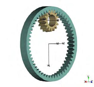
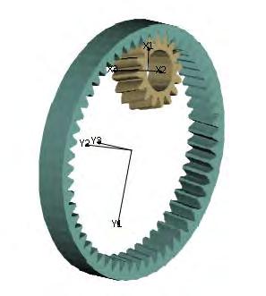
25 As another example, for the same Pinion and Gear Pitch Angles and Shaft Angle, the left gear set below has no Pinion Offset while the right gear set has a 10mm Pinion Offset. 0 mm Pinion Offset 10 mm Pinion Offset 29) Introduction of Internal Beveloid gears [new HyGEARS option] where either the Pinion, Gear or both can be Beveloid, and cut either with a Pivoted Work or Plunging Tool like external Beveloid gears. For example, left figure below, the Pinion has a -5 deg. Pitch Angle while that of the Gear is +5 deg. The end result is a gear set with // axes where shifting the Pinion axially allows backlash control. By contrast, right figure below, both the Pinion and Gear have the same Pitch Angle, and the result is a gear set where the axes are not //; however, shifting the pinion axially still allows backlash control. 25
26 26
KISSsoft 03/2013 Tutorial 15
 KISSsoft 03/2013 Tutorial 15 Bevel gears KISSsoft AG Rosengartenstrasse 4 8608 Bubikon Switzerland Tel: +41 55 254 20 50 Fax: +41 55 254 20 51 info@kisssoft.ag www.kisssoft.ag Contents 1 Starting KISSsoft...
KISSsoft 03/2017 Tutorial 15
 KISSsoft 03/2017 Tutorial 15 Bevel gears KISSsoft AG Rosengartenstrasse 4 8608 Bubikon Switzerland Tel: +41 55 254 20 50 Fax: +41 55 254 20 51 info@kisssoft.ag www.kisssoft.ag Contents 1 Starting KISSsoft...
Figure 1.1 "Bevel and hypoid gears" "Modules" Figure / August 2011 Release 03/2011
 KISSsoft Tutorial 015: Bevel Gears KISSsoft AG - +41 55 254 20 50 Uetzikon 4 - +41 55 254 20 51 8634 Hombrechtikon - info@kisssoft. AG Switzerland - www. KISSsoft. AG KISSsoft Tutorial: Bevel Gears 1 Starting
SECTION 8 BEVEL GEARING
 SECTION 8 BEVEL GEARING For intersecting shafts, bevel gears offer a good means of transmitting motion and power. Most transmissions occur at right angles, Figure 8-1, but the shaft angle can be any value.
Quindos the Ultimate Software package for Gears, Gear Tools and other Special Applications
 Quindos the Ultimate Software package for Gears, Gear Tools and other Special Applications Quindos gear packages Gearings Cylindrical Gear Unknown Gear Involute & Lead Master Straight Bevel Gear Spiral
Tribology Aspects in Angular Transmission Systems
 Tribology Aspects in Angular Transmission Systems Part VI: Beveloid & Hypoloid Gears Dr. Hermann Stadtfeld (This article is part six of an eight-part series on the tribology aspects of angular gear drives.
Program Internal Gear Set Profile Shift Coefficients With Zero Backlash Introduction
 Program 60-107 Internal Gear Set Profile Shift Coefficients With Zero Backlash Introduction The purpose of this model is to provide data for a gear set when the tooth thickness and/or the center distance
Part VII: Gear Systems: Analysis
 Part VII: Gear Systems: Analysis This section will review standard gear systems and will provide the basic tools to perform analysis on these systems. The areas covered in this section are: 1) Gears 101:
GPK for Design and Rating of Industrial Gearboxes
 GPK for Design and Rating of Industrial Gearboxes KISSsys models: Bevel-Helical gear package includes KISSsys models for single bevel gearbox (right angle gearbox) and bevel gearboxes including one to
Tribology Aspects in Angular Transmission Systems
 Tribology Aspects in Angular Transmission Systems Part II Straight Bevel Gears Dr. Hermann Stadtfeld (This is the second of an eight-part series on the tribology aspects of angular gear drives. Each article
KISSsoft Tutorial 012: Sizing of a fine pitch Planetary Gear set. 1 Task. 2 Starting KISSsoft
 KISSsoft Tutorial: Sizing of a fine pitch Planetary Gear set KISSsoft Tutorial 012: Sizing of a fine pitch Planetary Gear set For Release: 10/2008 kisssoft-tut-012-e-sizing-of-planetary-gear-set.doc Last
1.6 Features of common gears
 1.6 Features of common gears Chapter 1.2 covered briefly on types of gear. The main gear features are explained here. Helical gear Helical gear has characteristics of transferability of larger load, less
Gear Failures: Lessons Learned
 Return to Session Menu DYNAMIC POSITIONING CONFERENCE October 15-16, 2013 THRUSTERS SESSION Gear Failures: Lessons Learned Timo Rauti Rolls-Royce Gear Failures: Lessons learned Dynamic Positioning Conference
Lecture (7) on. Gear Measurement. By Dr. Emad M. Saad. Industrial Engineering Dept. Faculty of Engineering. Fayoum University.
 on. Gear Measurement. By Dr. Emad M. Saad. Industrial Engineering Dept. Faculty of Engineering. Fayoum University.") 1 Lecture (7) on Gear Measurement Fayoum University By Dr. Emad M. Saad Industrial Engineering Dept. Faculty of Engineering Fayoum University Faculty of Engineering Industrial Engineering Dept. 2015-2016
1 Lecture (7) on Gear Measurement Fayoum University By Dr. Emad M. Saad Industrial Engineering Dept. Faculty of Engineering Fayoum University Faculty of Engineering Industrial Engineering Dept. 2015-2016
KISSsys 03/2015 Instruction 010
 KISSsys 03/2015 Instruction 010 Positioning 07/04/2015 KISSsoft AG Rosengartenstrasse 4 8608 Bubikon Switzerland Tel: +41 55 254 20 50 Fax: +41 55 254 20 51 info@kisssoft.ag www.kisssoft.ag Contents 1.
Introduction. Kinematics and Dynamics of Machines. Involute profile. 7. Gears
 Introduction The kinematic function of gears is to transfer rotational motion from one shaft to another Kinematics and Dynamics of Machines 7. Gears Since these shafts may be parallel, perpendicular, or
1/2/2015 2:04 PM. Chapter 13. Gears General. Dr. Mohammad Suliman Abuhaiba, PE
 Chapter 13 Gears General 1 2 Chapter Outline 1. Types of Gears 2. Nomenclature 3. Conjugate Action 4. Involute Properties 5. Fundamentals 6. Contact Ratio 7. Interference 8. The Forming of Gear Teeth 9.
12/6/2013 9:09 PM. Chapter 13. Gears General. Dr. Mohammad Suliman Abuhaiba, PE
 Chapter 13 Gears General 1 2 Chapter Outline 1. Types of Gears 2. Nomenclature 3. Conjugate Action 4. Involute Properties 5. Fundamentals 6. Contact Ratio 7. Interference 8. The Forming of Gear Teeth 9.
CH#13 Gears-General. Drive and Driven Gears 3/13/2018
 CH#13 Gears-General A toothed wheel that engages another toothed mechanism in order to change the speed or direction of transmitted motion The gear set transmits rotary motion and force. Gears are used
11. GEAR TRANSMISSIONS
 11. GEAR TRANSMISSIONS 11.1. GENERAL CONSIDERATIONS Gears are one of the most important elements used in machinery. There are few mechanical devices that do not have the need to transmit power and motion
GPK for Design and Rating of Industrial Gearboxes
 KISSsoft AG - +41 55 254 20 50 Uetzikon 4 - +41 55 254 20 51 8634 Hombrechtikon - info@kisssoft.ag Switzerland - www.kisssoft.ag GPK for Design and Rating of Industrial Gearboxes KISSsys models: GPK geabox
 DEPARTMENT OF MECHANICAL ENGINEERING Subject code: ME6601 Subject Name: DESIGN OF TRANSMISSION SYSTEMS UNIT-I DESIGN OF TRANSMISSION SYSTEMS FOR FLEXIBLE ELEMENTS 1. What is the effect of centre distance
Determination and improvement of bevel gear efficiency by means of loaded TCA
 Determination and improvement of bevel gear efficiency by means of loaded TCA Dr. J. Thomas, Dr. C. Wirth, ZG GmbH, Germany Abstract Bevel and hypoid gears are widely used in automotive and industrial
Ernie Reiter and Irving Laskin
 F I N E P I T C H, P L A S T I C FA C E G E A R S : Design Ernie Reiter and Irving Laskin Ernie Reiter is a consultant specializing in the design of gears and geared products. He has authored modern software
KISSsoft 03/2018 Tutorial 6
 KISSsoft 03/2018 Tutorial 6 Shaft editor KISSsoft AG T. +41 55 254 20 50 A Gleason Company F. +41 55 254 20 51 Rosengartenstr. 4, 8608 Bubikon info@kisssoft.ag Switzerland www.kisssoft.ag Sharing Knowledge
ISO INTERNATIONAL STANDARD. Bevel and hypoid gear geometry. Géométrie des engrenages coniques et hypoïdes. First edition
 INTERNATIONAL STANDARD ISO 23509 First edition 2006-09-01 Bevel and hypoid gear geometry Géométrie des engrenages coniques et hypoïdes Reference number ISO 2006 Provläsningsexemplar / Preview PDF disclaimer
INVOLUTE SPIRAL FACE COUPLINGS AND GEARS: DESIGN APPROACH AND MANUFACTURING TECHNIQUE
 УДК 621.9.015 Dr. Alexander L. Kapelevich, Stephen D. Korosec 38 INVOLUTE SPIRAL FACE COUPLINGS AND GEARS: DESIGN APPROACH AND MANUFACTURING TECHNIQUE This paper presents spiral face gears with an involute
LAPPING OR GRINDING? WHICH TECHNOLOGY IS THE RIGHT CHOICE IN THE AGE OF INDUSTRY 4.0?
 LAPPING OR GRINDING? WHICH TECHNOLOGY IS THE RIGHT CHOICE IN THE AGE OF INDUSTRY 4.0? Bevel gear transmissions for the automotive industry are subject to extremely stringent requirements. They must be
GMS 32. Double flank testing machine for gears
 GMS 32 Double flank testing machine gears Specifications max. diameter of measured gear 100 mm (4'') max. diameter of master gear 80 mm center distance 0... 90mm max. weight of gear 0.5 kg max. testing
Spiroid High Torque Skew Axis Gearing A TECHNICAL PRIMER F. EVERTZ, M. GANGIREDDY, B. MORK, T. PORTER & A. QUIST
 2016 Spiroid High Torque Skew Axis Gearing A TECHNICAL PRIMER F. EVERTZ, M. GANGIREDDY, B. MORK, T. PORTER & A. QUIST Table of Contents INTRODUCTION PAGE 02 SPIROID GEAR SET CHARACTERISTICS PAGE 03 BASIC
KISSsoft 03/2018 Tutorial 7
 KISSsoft 03/2018 Tutorial 7 Roller bearings KISSsoft AG T. +41 55 254 20 50 A Gleason Company F. +41 55 254 20 51 Rosengartenstr. 4, 8608 Bubikon info@kisssoft.ag Switzerland www.kisssoft.ag Sharing Knowledge
DRAFT. KISSsoft Release 03/2013. Changes from Release 03/2012 to Release 03/2013. KISSsoft AG Rosengartenstrasse Bubikon Switzerland
 KISSsoft Release 03/2013 Changes from Release 03/2012 to Release 03/2013 DRAFT KISSsoft AG Rosengartenstrasse 4 8608 Bubikon Switzerland Tel: +41 55 254 20 50 Fax: +41 55 254 20 51 info@kisssoft.ag www.kisssoft.ag
Chapter 8 Kinematics of Gears
 Chapter 8 Kinematics of Gears Gears! Gears are most often used in transmissions to convert an electric motor s high speed and low torque to a shaft s requirements for low speed high torque: Speed is easy
Program Center Distance Change
 Introduction Program 60-146--Center Distance Change When the coefficient of thermal expansion of the material used for gears is different from the coefficient for the mountg or housg material, it is necessary
Gear Tooth Geometry - This is determined primarily by pitch, depth and pressure angle
 Gear Tooth Geometry - This is determined primarily by pitch, depth and pressure angle Addendum: The radial distance between the top land and the pitch circle. Addendum Circle: The circle defining the outer
KISSsoft 03/2018 Tutorial 4
 KISSsoft 03/2018 Tutorial 4 Bolt calculation according to VDI 2230 KISSsoft AG T. +41 55 254 20 50 A Gleason Company F. +41 55 254 20 51 Rosengartenstr. 4, 8608 Bubikon info@kisssoft.ag Switzerland www.kisssoft.ag
Spur Gears. Helical Gears. Bevel Gears. Worm Gears
 Spur s General: Spur gears are the most commonly used gear type. They are characterized by teeth which are perpendicular to the face of the gear. Spur gears are by far the most commonly available, and
The Basics of Gear Theory, Part 2
 The Basics of Gear Theory, Part 2 Hermann J. Stadtfeld Bevel Gears: By the Book Introduction (Chapter 1, Part 2) The first part of this publication series covered the general basics of involute gearing
KISSsoft 03/2016 Tutorial 7
 KISSsoft 03/2016 Tutorial 7 Roller bearings KISSsoft AG Rosengartenstrasse 4 8608 Bubikon Switzerland Tel: +41 55 254 20 50 Fax: +41 55 254 20 51 info@kisssoft.ag www.kisssoft.ag Contents 1 Task... 3 1.1
The Geometry of Involute Gears
 The Geometry of Involute Gears J.R. Colbourne The Geometry of Involute Gears With 217 Illustrations Springer-Verlag New York Berlin Heidelberg London Paris Tokyo J.R. Colbourne Department of Mechanical
11/23/2013. Chapter 13. Gear Trains. Dr. Mohammad Suliman Abuhiba, PE
 Chapter 13 Gear Trains 1 2 13.2. Types of Gear Trains 1. Simple gear train 2. Compound gear train 3. Reverted gear train 4. Epicyclic gear train: axes of shafts on which the gears are mounted may move
Gear Measurement. Lecture (7) Mechanical Measurements
 Mechanical Measurements") 18 3. Gear profile checking 2. Involute measuring machine In this method the gear is held on a mandrel and circular disc of same diameter as the base circle of gear for the measurement is fixed on the
18 3. Gear profile checking 2. Involute measuring machine In this method the gear is held on a mandrel and circular disc of same diameter as the base circle of gear for the measurement is fixed on the
Instantaneous Centre Method
 Instantaneous Centre Method The combined motion of rotation and translation of the link AB may be assumed to be a motion of pure rotation about some centre I, known as the instantaneous centre of rotation.
Southwestern Industries, Inc. TRAK K3SX Knee Mill Specifications with the ProtoTRAK SMX Control
 Southwestern Industries, Inc. TRAK K3SX Knee Mill Specifications with the ProtoTRAK SMX Control Machine Specifications Table Size 50 X 10 T-Slots 5/8 x 3 x 2 ½ Table Travel 32 Saddle Travel 16 Knee Travel
DUDLEY'S" HANDBOOK OF PRACTICAL GEAR DESIGN AND MANUFACTURE. Stephen P. Radzevich
 Second Edition DUDLEY'S" HANDBOOK OF PRACTICAL GEAR DESIGN AND MANUFACTURE Stephen P. Radzevich LßP) CRC Press VV J Taylors Francis Group Boca Raton London New York CRC Press is an imprint of the Taylor
CHAPTER 3 page 35 PRINCIPLES OF GEAR-TOOTH GENERATION. .1 Angular Velocity Ratio
 CHAPTER 1 page 1..., ATURE, NOTATION AND CONVENTIONS TYPES OF GEAR 1.1 Spur 1.2 Helical 1.3 Double-Helical 1.4 Crossed Helical 1.5 Conical Involute 1.6 Bevel 1.7 Spiral Bevel 1.8 Hypoid 1.9 Worm NOMENCLATURE
Bevel and hypoid gear geometry
 Provläsningsexemplar / Preview INTERNATIONAL STANDARD ISO 23509 Second edition 2016-11-15 Bevel and hypoid gear geometry Géométrie des engrenages coniques et hypoïdes Reference number ISO 2016 Provläsningsexemplar
GEAR CONTENTS POWER TRANSMISSION GEAR TYPES OF GEARS NOMENCLATURE APPLICATIONS OF GEARS VELOCITY RATIO GEAR TRAINS EXAMPLE PROBLEMS AND QUESTIONS
 GEAR CONTENTS POWER TRANSMISSION GEAR TYPES OF GEARS NOMENCLATURE APPLICATIONS OF GEARS VELOCITY RATIO GEAR TRAINS EXAMPLE PROBLEMS AND QUESTIONS GEAR.. Power transmission is the movement of energy from
ANALYSIS OF GEAR QUALITY CRITERIA AND PERFORMANCE OF CURVED FACE WIDTH SPUR GEARS
 8 FASCICLE VIII, 8 (XIV), ISSN 11-459 Paper presented at Bucharest, Romania ANALYSIS OF GEAR QUALITY CRITERIA AND PERFORMANCE OF CURVED FACE WIDTH SPUR GEARS Laurentia ANDREI 1), Gabriel ANDREI 1) T, Douglas
KINGS COLLEGE OF ENGINEERING DEPARTMENT OF MECHANICAL ENGINEERING
 KINGS COLLEGE OF ENGINEERING DEPARTMENT OF MECHANICAL ENGINEERING QUESTION BANK Sub Code/Name: ME 1352 DESIGN OF TRANSMISSION SYSTEMS Year/Sem: III / VI UNIT-I (Design of transmission systems for flexible
BEVELGEAR. Competence and Performance.
 BEVELGEAR Competence and Performance www.graessner.de General Advantages of Spiral, Hypoid and Zerol Bevel Gears High level of coverage due to the fact that several teeth are meshed simultaneously Resistant
Catalog Q Conversion For those wishing to ease themselves into working with metric gears
 1.3.4 Conversion For those wishing to ease themselves into working with metric gears by looking at them in terms of familiar inch gearing relationships and mathematics, Table 1-5 is offered as a means
Southwestern Industries, Inc. TRAK DPM FHM7 Bed Mill with the ProtoTRAK SMX CNC
 Southwestern Industries, Inc. TRAK DPM FHM7 Bed Mill with the ProtoTRAK SMX CNC Machine specifications Table size 76 x 14 T-slots (number x width x pitch) 3 x 63 x 2.48 Travel (X, Y, Z axis) 60 x 23 x
AN OPTIMAL PROFILE AND LEAD MODIFICATION IN CYLINDRICAL GEAR TOOTH BY REDUCING THE LOAD DISTRIBUTION FACTOR
 AN OPTIMAL PROFILE AND LEAD MODIFICATION IN CYLINDRICAL GEAR TOOTH BY REDUCING THE LOAD DISTRIBUTION FACTOR Balasubramanian Narayanan Department of Production Engineering, Sathyabama University, Chennai,
How to Achieve a Successful Molded Gear Transmission
 How to Achieve a Successful Molded Gear Transmission Rod Kleiss Figure 1 A molding insert tool alongside the molded gear and the gear cavitiy. Molded plastic gears have very little in common with machined
Automate Your Designs A Hands-On Experience
 Craig Ruchti, Solid Edge Field Support Applications Engineer Automate Your Designs A Hands-On Experience Solid Edge University 2014 May 12-14, Atlanta, GA, USA SOLID EDGE UNIVERSITY 2014 Re-imagine What
Tendenze attuali nei metodi di calcolo per progettare gearbox Dr. Ulrich Kissling KISSsoft AG, Bubikon, Svizzera
 Tendenze attuali nei metodi di calcolo per progettare gearbox Dr. Ulrich Kissling KISSsoft AG, Bubikon, Svizzera Tendenze attuali nei metodi di calcolo per progettare gearbox - Standardized Gear Calculation
50 g 50 e g ars e o ars lut o i lut on o s n.c s o.c m o
 50 gearsolutions.com Analysis and Optimization of Asymmetric Epicyclic Gears By Alexander L. Kapelevich Following the Direct Gear Design approach to asymmetric epicyclic gear stages with singular and compound
Southwestern Industries, Inc. DPM SX5P Bed Mill Specifications with the ProtoTRAK SMX3 Control
 Southwestern Industries, Inc. DPM SX5P Bed Mill Specifications with the ProtoTRAK SMX3 Control Machine Specifications Table Size 50 x 12 T-Slots (number x width x pitch) - 3 x.63" x 2.52" Travel (X, Y,
Issue 2.0 December EPAS Midi User Manual EPAS35
 Issue 2.0 December 2017 EPAS Midi EPAS35 CONTENTS 1 Introduction 4 1.1 What is EPAS Desktop Pro? 4 1.2 About This Manual 4 1.3 Typographical Conventions 5 1.4 Getting Technical Support 5 2 Getting Started
Bibliography. [1] Buckingham, Earle: "Analytical Mechanics of Gears", McGraw-Hill, New York, 1949, and republished by Dover, New York, 1963.
![Bibliography. [1] Buckingham, Earle: Analytical Mechanics of Gears, McGraw-Hill, New York, 1949, and republished by Dover, New York, 1963.](/thumbs/87/96820687.jpg "Bibliography. [1] Buckingham, Earle: Analytical Mechanics of Gears, McGraw-Hill, New York, 1949, and republished by Dover, New York, 1963.") Bibliography The first five references listed are books on gearing. Some of them deal not only with the geometry, but also with many other aspects of gearing. However, the books are included in this bibliography
Bibliography The first five references listed are books on gearing. Some of them deal not only with the geometry, but also with many other aspects of gearing. However, the books are included in this bibliography
Available in July 2010
 Available in July 2010 SGFD/SGFK/SGCPFD Ground acks m0.5~ 18 items engths : 0, 0 and 1000mm CP5~20 8 items engths : 0 and 1000mm The product line-up for the popular J-Series has expanded! Quick-touse Ground
(POWER TRANSMISSION Methods)
") UNIT-5 (POWER TRANSMISSION Methods) It is a method by which you can transfer cyclic motion from one place to another or one pulley to another pulley. The ways by which we can transfer cyclic motion are:-
UNIT-5 (POWER TRANSMISSION Methods) It is a method by which you can transfer cyclic motion from one place to another or one pulley to another pulley. The ways by which we can transfer cyclic motion are:-
Lecture 13 BEVEL GEARS
 Lecture 13 BEVEL GEARS CONTENTS 1. Bevel gear geometry and terminology 2. Bevel gear force analysis 3. Bending stress analysis 4. Contact stress analysis 5. Permissible bending fatigue stress 6. Permissible
Metrology Prof. Dr Kanakuppi Sadashivappa Bapuji Institute of Engineering and Technology Davangere. Lecture 25 Introduction of Gears
 Metrology Prof. Dr Kanakuppi Sadashivappa Bapuji Institute of Engineering and Technology Davangere Lecture 25 Introduction of Gears I welcome you for the series of lecture on gear measurement and at module
GEAR NOISE REDUCTION BY NEW APPROACHES IN GEAR FINISHING PROCESSES
 GEAR NOISE REDUCTION BY NEW APPROACHES IN GEAR FINISHING PROCESSES Nikam Akshay 1, Patil Shubham 2, Pathak Mayur 3, Pattewar Vitthal 4, Rawanpalle Mangesh 5 1,2,3,4,5 Department of Mechanical Engineering,
Sheet 1 Variable loading
 Sheet 1 Variable loading 1. Estimate S e for the following materials: a. AISI 1020 CD steel. b. AISI 1080 HR steel. c. 2024 T3 aluminum. d. AISI 4340 steel heat-treated to a tensile strength of 1700 MPa.
WIRELESS BLOCKAGE MONITOR OPERATOR S MANUAL
 WIRELESS BLOCKAGE MONITOR OPERATOR S MANUAL FOR TECHNICAL SUPPORT: TELEPHONE: (701) 356-9222 E-MAIL: support@intelligentag.com Wireless Blockage Monitor Operator s Guide 2011 2012 Intelligent Agricultural
Tube Bender. Machine Type - Tube Bender
 Tube Bender Machine Type - Tube Bender Tube Bender Control Mach4 Tube Bender Control Manual X15-250-300 Tube Bender Control Manual X15-250-400 Tube Bender Wiring Guide X15-250-300 Tube Bender Control Mach4
Bevel Gears. Catalog Number of KHK Stock Gears. Bevel Gears M BS G R. Gears. Spur. Helical. Gears. Internal. Gears. Racks. CP Racks.
 MHP High-Ratio Hypoid Ground Spiral G Ground Spiral 15 ~ 200 2 m1, 1.5 Page 456 m2 ~ 4 Page 458 m2 ~ 4 Page 460 Spur MBSA MBSB Finished Bore Spiral Spiral 1.5 ~ 4 SBZG Ground Zerol 1.5, 2 Helical m2 ~
1.8 Rack shift of the gear
 1.8 Rack shift of the gear Undercut When Number of teeth is belo minimum as shon in Fig. 3, part of dedendum is no longer an Involute curve but ill look like a shape scooped out by cutter tool. Refer to
126 Ridge Road Tel: (607) PO Box 187 Fax: (607)
 PO Box 187 Fax: (607)") 1. Summary Finite element modeling has been used to determine deflections and stress levels within the SRC planar undulator. Of principal concern is the shift in the magnetic centerline and the rotation
1. Summary Finite element modeling has been used to determine deflections and stress levels within the SRC planar undulator. Of principal concern is the shift in the magnetic centerline and the rotation
Tutorial: Calculation of two shafts connected by a rolling bearing
 Tutorial: Calculation of two shafts connected by a rolling bearing This tutorial shows the usage of MESYS shaft calculation with multiple shafts. The shaft calculation software provides different views
ScienceDirect A NEW EXPERIMENTAL APPROACH TO TEST OPEN GEARS FOR WINCH DRUMS
 Available online at www.sciencedirect.com ScienceDirect Procedia Engineering 133 (2015 ) 192 201 6th Fatigue Design conference, Fatigue Design 2015 A NEW EXPERIMENTAL APPROACH TO TEST OPEN GEARS FOR WINCH
bearing to conform to the same elliptical shape as the wave generator plug.
 32 Gear Product News April 2006 t h e b a s i c s o f H a r m o n i c D r i v e G e a r i n g Anthony Lauletta H armonic drives were invented in the late 1950s and have been a major part of the motion
Thermal Analysis of Helical and Spiral Gear Train
 International Journal for Ignited Minds (IJIMIINDS) Thermal Analysis of Helical and Spiral Gear Train Dr. D V Ghewade a, S S Nagarale b & A N Pandav c a Principal, Department of Mechanical, GENESIS, Top-Kolhapur,
UNIT -I. Ans: They are specified by the no. of strands & the no. of wires in each strand.
 VETRI VINAYAHA COLLEGE OF ENGINEERING AND TECHNOLOGY, THOTTIAM, NAMAKKAL-621215. DEPARTMENT OF MECHANICAL ENGINEERING SIXTH SEMESTER / III YEAR ME6601 DESIGN OF TRANSMISSION SYSTEM (Regulation-2013) UNIT
ME6601 DESIGN OF TRANSMISSION SYSTEMS
 SYED AMMAL ENGINEERING COLLEGE (Approved by the AICTE, New Delhi, Govt. of Tamilnadu and Affiliated to Anna University, Chennai) Established in 1998 - An ISO 9001:2008 Certified Institution Dr. E.M.Abdullah
Direction of Helix (R) No. of Teeth (20) Module (1) Others (Ground Gear) Type (Helical Gear) Material (SCM440)
 No. of Teeth (20) Module (1) Others (Ground Gear) Type (Helical Gear) Material (SCM440)") KH round Series Newly added m1 ~ 3 Page 168 SH Steel m2, 3 Page 178 CP acks acks Catalog Number of KHK Stock The Catalog Number for KHK stock gears is based on the simple formula listed below. Please order
KH round Series Newly added m1 ~ 3 Page 168 SH Steel m2, 3 Page 178 CP acks acks Catalog Number of KHK Stock The Catalog Number for KHK stock gears is based on the simple formula listed below. Please order
MicroGuard 586 Retrofit Rated Capacity Indicator System. Calibration and Testing for:
 GREER COMPANY Page 1 of 22 MicroGuard 586 Retrofit Rated Capacity Indicator System Machine Model Serial Number Tester Date Calibration and Testing for: GREER COMPANY Page 2 of 22 MicroGuard 586 Retrofit
Chapter seven. Gears. Laith Batarseh
 Chapter seven Gears Laith Batarseh Gears are very important in power transmission between a drive rotor and driven rotor What are the functions of gears? - Transmit motion and torque (power) between shafts
CASE STUDY OF ASSEMBLY ERRORS INFLUENCE ON STRESS DISTRIBUTION IN SPUR GEAR TRAIN
 Proceedings of the 7th International Conference on Mechanics and Materials in Design Albufeira/Portugal 11-15 June 2017. Editors J.F. Silva Gomes and S.A. Meguid. Publ. INEGI/FEUP (2017) PAPER REF: 6564
Verifying the accuracy of involute gear measuring machines R.C. Frazer and J. Hu Design Unit, Stephenson Building, University ofnewcastle upon Tyne,
 Verifying the accuracy of involute gear measuring machines R.C. Frazer and J. Hu Design Unit, Stephenson Building, University ofnewcastle upon Tyne, Abstract This paper describes the most common methods
CHAPTER 6 GEARS CHAPTER LEARNING OBJECTIVES
 CHAPTER 6 GEARS CHAPTER LEARNING OBJECTIVES Upon completion of this chapter, you should be able to do the following: Compare the types of gears and their advantages. Did you ever take a clock apart to
Small Tool Instruments and Data Management
 Small Tool Instruments and Data Management Digital Micrometers Pages 28 34 Analogue Micrometers Pages 35 42 Special Version Micrometers Pages 43 63 External screw type micrometers accessories Pages 65
BFF Motorised Trim Wheel - Set-up
 BFF Motorised Trim Wheel - Set-up Table of Contents Summary of Set-up Steps...1 BFF Motorised Trim Wheel - Setup Details...2 Final Set-Up For Direct Connection To FSUIPC/XPUIPC...5 Final Set-Up For Direct
SECTION 4 SPUR GEAR CALCULATIONS
 Function of α, or invα, is known as involute function. Involute function is very important in gear design. Involute function values can be obtained from appropriate tables. With the 3.1 Contact Ratio center
Technology of Machine Tools
 PowerPoint to accompany Technology of Machine Tools 6 th Edition Krar Gill Smid Gear Cutting Unit 70 Copyright The McGraw-Hill Companies, Inc. Permission required for reproduction or display. 70-2 Objectives
ANALYSIS OF SURFACE CONTACT STRESS FOR A SPUR GEAR OF MATERIAL STEEL 15NI2CR1MO28
 ANALYSIS OF SURFACE CONTACT STRESS FOR A SPUR GEAR OF MATERIAL STEEL 15NI2CR1MO28 D. S. Balaji, S. Prabhakaran and J. Harish Kumar Department of Mechanical Engineering, Chennai, India E-Mail: balajimailer@gmail.com
Improvements for Ver November 23, 2017
 Dyrobes Rotordynamics Software dyrobes.com Improvements for Ver 20.00 November 23, 2017 Add new features in BePerf for fixed-lobe and tilting pad journal bearing design: 1) Parametric study 2) Design Comparison.
Appendix X New Features in v2.4 B
 Appendix X New Features in v2.4 B Version 2.4B adds several features, which we have grouped into these categories: New Suspension Types or Options The program now allows for solid front axles and for several
General gear terms and definitions. Trantorque 48 DP. Steel and Brass
 General gear terms and definitions 317 Spur and Helical Gears: Formulae and definitions Helical Gear Spur Gear Term Definition formulae formulae 318 Spur and Helical Gears: Formulae and definitions Helical
Model Library Power Transmission
 Model Library Power Transmission The Power Transmission libraries in SimulationX support the efficient modeling and analysis of mechanical powertrains as well as the simulation-based design of controlled
Lesson 8: A Compound Spur Gear Train
 Lesson 8: A Compound Spur Gear Train Goal: -Create Assembly -Create Proper Gear Mates -Create Motion Study -Graph Angular velocity of Output Gear MAKE SURE YOU ARE IN MILLIMETERS FOR THIS EXERCISE Creating
1 135 teeth to rack
 1. A spur gear with 46 teeth, 2.5 module has to be cut on a column and knee type horizontal milling machine with a rotary disc type form gear milling cutter. The 2.5 module cutter no. 3 is used on a blank
Effect of Geometry Factor I & J Factor Multipliers in the performance of Helical Gears
 Effect of Geometry Factor I & J Factor Multipliers in the performance of Helical Gears 1 Amit D. Modi, 2 Manan B. Raval, 1 Lecturer, 2 Lecturer, 1 Department of Mechanical Engineering, 2 Department of
Chapter 3. Transmission Components
 Chapter 3. Transmission Components The difference between machine design and structure design An important design problem in a mechanical system is how to transmit and convert power to achieve required
Standard Scales SERIES 182 Made of Low-Expansion Glass. Working Standard Scales SERIES 182 E-32
 Standard Scales SERIES 182 Made of Low-Expansion Glass High-precision glass scales manufactured under Mitutoyo s leading-edge Linear Scale production technology. High accuracy is guaranteed to be used
Engineering Information
 Engineering nformation Gear Nomenclature ADDENDUM (a) is the height by which a tooth projects beyond the pitch circle or pitch line. BASE DAMETER (D b ) is the diameter of the base cylinder from which
MMS Spiral Miter Gears. SMS Spiral Miter Gears. m1 ~ 8 Page 268. SAM Angular Miter Gears. m1 ~ 4 Page 278. Direction of Spiral ( R )
") Miter Spur MMSG Ground Spiral Miter SMSG Ground Spiral Miter MMSA MMSB Finished Bore Spiral Miter MMS Spiral Miter SMS Spiral Miter SMZG Ground Zerol Miter SMA SMB SMC Finished Bore Miter Series Series
Miter Spur MMSG Ground Spiral Miter SMSG Ground Spiral Miter MMSA MMSB Finished Bore Spiral Miter MMS Spiral Miter SMS Spiral Miter SMZG Ground Zerol Miter SMA SMB SMC Finished Bore Miter Series Series