UNIT -I. Ans: They are specified by the no. of strands & the no. of wires in each strand.
|
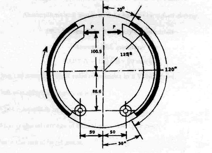
|
|
- Sarah Rice
- 6 years ago
- Views:
Transcription
 UNIT -I PART-A 1. How is a Wire rope specified? Ans: They are specified by the no.")
1 VETRI VINAYAHA COLLEGE OF ENGINEERING AND TECHNOLOGY, THOTTIAM, NAMAKKAL DEPARTMENT OF MECHANICAL ENGINEERING SIXTH SEMESTER / III YEAR ME6601 DESIGN OF TRANSMISSION SYSTEM (Regulation-2013) UNIT -I PART-A 1. How is a Wire rope specified? Ans: They are specified by the no. of strands & the no. of wires in each strand. 2. Sketch the cross section of a V-belt and label its important parts. 3. Why is the face of a pulley crowned? Ans: The crowning tends to keep the belt in centre on a pulley rim while in motion. 4. What are the five parts of roller chain? Ans: Pin link, Roller link, Pins, Bushes & Roller 5. Give the relationship of ratio of tensions in a V-belt drive. Ans: T 1 /T 2 =e μα.cosecβ 6. What is a silent chain? In what situations, silent chains are preferred? Ans: i) Inverted tooth chains are called silent chains because of their relatively quiet operation. ii) They are preferred for high-power, high speed & smooth operation 7. Define maximum tension in a belt. Ans: Tension on tight side of the belt + Centrifugal tension 8. Give the condition for maximum power transmission in terms of centrifugal tension in case of belt drive. Ans: The power transmitted shall be maximum when the centrifugal tension (Tc) is one third of the maximum belt tension (T).


2 9. Why tight side of the flat belt should be at the bottom side of the pulley? Ans: Because the driving pulley pulls the belt from bottom side and delivers it to the upper side. So it is obvious that the bottom side of the belt is tight. 10. What is meant by chordal action of chain? Ans: When chain passes over the sprocket, it moves as a series of chords instead of a continuous arc as in the case of a belt drive. It results in varying speed of the chain drive. This phenomenon is known as chordal action. PART-B
3
4 UNIT -II PART-A 1. Mention a few gear materials. Ans: Metallic gears steel, cast iron Non-Metallic gears wood, compressed paper & synthetic resins 2. State an advantage and disadvantage of helical gear. Ans: Advantage: Produce less noise than spur gears Dis Advantage: Subjected to axial thrust loads 3. Why is tangential component of gear tooth force called useful component? Ans: Because it transmits power. 4. Compare the contact between mating teeth of spur and helical gears. Ans: i) In spur gears the line of contact is parallel to the axis of rotation. The total length of contact line is equal to the face width. ii) In helical gears the line of contact is diagonal across the face of the tooth. The total length of contact line is greater than the face width. This lowers the unit loading & increases load carrying capacity. 5. What is backlash in gears? Ans: It is the difference between the tooth space and the tooth thickness along the pitch circle. 6. What is the advantage of helical gear over spur gear? Ans: i) Helical gears produce less noise than spur gears. ii) Helical gears have a greater load capacity than equivalent spur gears. 7. Why is a gear tooth subjected to dynamic loading? Ans: Inaccuracies of tooth spacing, Irregularities in tooth profiles, Misalignment between bearings. 8. State the law of gearing or conditions of correct gearing. Ans: It states that for obtaining a constant velocity ratio, at any instant of teeth the common normal at each of contact should always pass through a pitch point, situated on the line joining the centers of rotation of the pair of mating parts. 9. What are the commonly used gear tooth profiles? Ans: Involute & Cycloidal 10. State about herring bone gear. Ans: The double helical gears connecting two parallel shafts are known as herringbone gears. They are used in heavy machinery and gear boxes.
5 PART B
6
7
8 UNIT -III PART-A 1. When do we employ crossed helical gear? Ans: A pair of crossed-helical gears also known as spiral gears are used to connect and transmit motion between two non-parallel and non- intersecting shafts. As the contact between the mating teeth is always a point, these gears are suitable only for transmitting a small amount of power. 2. Mention two characteristics of hypoid gear. Ans: They are similar in appearance to spiral-bevel gears. Their pitch surfaces are hyperboloids rather than cones. Axis of pinion is offset from the axis of the gear. 3. What are the various forces acting on a bevel gear? Ans: Tangential force, Axial force & Radial force 4. Usually worm is made of hard material and worm gear is made of softer material justify. Ans: A material strength is set so that an amount of wear of the worm becomes larger that of the worm wheel. 5. When is bevel gear preferred? Ans: They are used to transmit power between two intersecting shafts. 6. Calculate the angle between the shafts of a crossed helical gears made of two right handed helical gears of 15 helix angle each. Ans:Shaft angle, Ө = β1 + β2 = 2β = 2 (15 ) = State the use of bevel gears. Ans: They are used to transmit power between two intersecting shafts. 8. State the advantage of worm gear drive in weight lifting machine. Ans: The worm gear drives are irreversible. It means that the motion cannot be transmitted from worm wheel to the worm. This property of irreversible is advantageous in load hoisting applications like cranes and lifts. 9. Why is the crossed helical gear drive not used for power transmission? Ans: As the contact between the mating teeth of crossed helical gears is always a point, these gears are suitable only for transmitting a small amount of power. That s why mostly these gears are not used for power transmission. 10. Why is the efficiency of a worm gear drive comparatively low? Ans: Because of power loss due to friction caused by sliding.
9 PART B
10
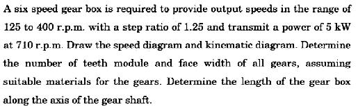
11 UNIT -IV PART-A 1. What are the points to be considered while designing a sliding mesh type of multi-speed gear box? Ans: i) The transmission ratio in a gear box is limited by ¼ < i < 2 ii) Speed ratio of any stage should not be greater than Which type of gear is used in constant mesh gear box? Justify. Ans: Helical gears are used in constant mesh gear boxes to provide quieter and smooth operation. 3. Compare sliding mesh and synchromesh gear box. Ans: sliding mesh gear box: It derives its name from the fact that the meshing of the gears takes place by sliding of gears on each other. With sliding mesh gear box, double de-clutching is necessary to bring the two sets of dog teeth to the same speed so that they can be slid into engagement quietly. Synchromesh gear box: To eliminate the need to de-clutch, the synchromesh gear box was introduced. The basic gear box is laid out in the same manner as the constant mesh, but with the addition of a cone clutch fitted between the dog and gear members. 4. Where is multi-speed gear boxes employed? Ans: They are employed wherever the variable spindle speeds are necessary. 5. Name the series in which speeds are arranged in multi-speed gear boxes. Ans: Basic series of preferred numbers are R5, R10, R20, R40 & R List six standard speeds starting from 18 rpm with a step ratio 1.4. Ans: For the step ratio Φ = 1.4, the R20 series, the standard speeds are 18, 20, 22.4, 25, 28 & 31.5 rpm. 7. Sketch the kinematic layout of gears for 3 speeds between two shafts. Ans: Refer page.no: 9.11 Dots by V.Jayakumar 8. Differentiate ray diagram and structural diagram. Ans: Ray diagram is a graphical representation of the structural formula. Structural diagram is a kinematic layout that shows the arrangement of gears in a gear box. 9. List out the basic rules to be followed for optimum gear box design. Ans: i) The transmission ratio in a gear box is limited by ¼ < =i < 2 ii) Speed ratio of any stage should not be greater than What is step ratio? Name the series in which speeds of multi-speed gear box are arranged. Ans: When the spindle speeds are arranged in geometric progression, then the ratio between the two adjacent speeds is


12 PART B known as speed ratio. Basic series are R5, R10, and R20 & R40.
13
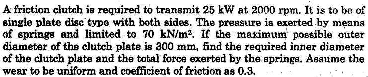
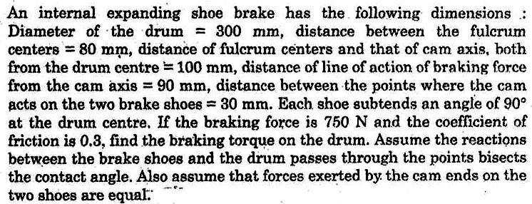
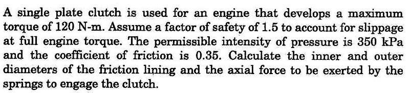
14 UNIT V PART-A 1. Name the profile of cam that gives no jerk. Ans: Circle arc cam gives no jerk. Because the derivative of acceleration of cam is zero. 2. Give the reasons for left and right shoes of the internal expansion brakes having different actuating forces. Ans: Depending upon the direction of the drum rotation, one shoe would be a leading shoe and another shoe is a trailing shoe. The leading shoe is self energizing whereas the trailing shoe is not. In the leading shoe, the friction force helps the applied force and hence more actuating force than the trailing force. 3. What are the effects of temperature rise in clutches? Ans: i) Excessive surface temperature results in premature clutch failure. ii) May cause the individual plates to be welded together in metal clutches. iii) May cause excessive wear in non-metal clutches. 4. What is the significance of pressure angle in cam design? Ans: The pressure angle is very important in cam design as it represents steepness of the cam profile. If the pressure angle is too large, a reciprocating follower will jam in its bearings. 5. State the advantage of cam mechanisms. Ans: Cams are used for transmitting desired motion to a follower by direct contact. Cam mechanisms are used in the operation of IC engine valves. 6. How the uniform rate of wear assumption is valid for clutches? Ans: In clutches, the value of normal pressure, axial load for the given clutch is limited by the rate of wear that can be tolerated in the brake linings. Moreover, the assumption of uniform rate wear gives a lower calculated clutch capacity than the assumption of uniform pressure. Hence clutches are usually designed on the basis of uniform wear. 7. Name four profiles normally used in cams. Ans: Uniform velocity, Simple harmonic motion, Uniform acceleration & retardation, Cycloidal motion. 8. Under what condition of a clutch, uniform rate of wear assumption is more valid? Ans: If the clutch is old one. 9. When do we use multiple disk clutches? Ans: It is used when large amount of torque is to be transmitted. In a multi plate clutch, the number of frictional linings and the metal plates are increased which increases the capacity of the clutch to transmit torque. 10. Differentiate between self-energizing and self-locking brakes. Ans: When the frictional force is sufficient enough to apply the brake with no external force, then the brake is said to
15 be self-locking brake. When the frictional force helps in applying the brake, then the brake is said to be self-energised brake.
16 PART-B
17
18
19
20
ME6601 DESIGN OF TRANSMISSION SYSTEMS
 SYED AMMAL ENGINEERING COLLEGE (Approved by the AICTE, New Delhi, Govt. of Tamilnadu and Affiliated to Anna University, Chennai) Established in 1998 - An ISO 9001:2008 Certified Institution Dr. E.M.Abdullah
 DEPARTMENT OF MECHANICAL ENGINEERING Subject code: ME6601 Subject Name: DESIGN OF TRANSMISSION SYSTEMS UNIT-I DESIGN OF TRANSMISSION SYSTEMS FOR FLEXIBLE ELEMENTS 1. What is the effect of centre distance
KINGS COLLEGE OF ENGINEERING DEPARTMENT OF MECHANICAL ENGINEERING
 KINGS COLLEGE OF ENGINEERING DEPARTMENT OF MECHANICAL ENGINEERING QUESTION BANK Sub Code/Name: ME 1352 DESIGN OF TRANSMISSION SYSTEMS Year/Sem: III / VI UNIT-I (Design of transmission systems for flexible
CHENDU COLLEGE OF ENGINEERING & TECHNOLOGY DEPARTMENT OF MECHANICAL ENGINEERING QUESTION BANK
 CHENDU COLLEGE OF ENGINEERING & TECHNOLOGY DEPARTMENT OF MECHANICAL ENGINEERING QUESTION BANK Sub Code: ME 2342 DESIGN OF TRANSMISSION SYSTEM UNIT - I 1. How the bevel gears are classified? Explain with
DHANALAKSHMI COLLEGE OF ENGINEERING
 DHANALAKSHMI COLLEGE OF ENGINEERING (Dr.VPR Nagar, Manimangalam, Tambaram) Chennai - 601 301 DEPARTMENT OF MECHANICAL ENGINEERING III YEAR MECHANICAL - VI SEMESTER ME 6601 DESIGN OF TRANSMISSION SYSTEMS
Part VII: Gear Systems: Analysis
 Part VII: Gear Systems: Analysis This section will review standard gear systems and will provide the basic tools to perform analysis on these systems. The areas covered in this section are: 1) Gears 101:
ME6401 KINEMATICS OF MACHINERY UNIT- I (Basics of Mechanism)
") ME6401 KINEMATICS OF MACHINERY UNIT- I (Basics of Mechanism) 1) Define resistant body. 2) Define Link or Element 3) Differentiate Machine and Structure 4) Define Kinematic Pair. 5) Define Kinematic Chain.
ME6401 KINEMATICS OF MACHINERY UNIT- I (Basics of Mechanism) 1) Define resistant body. 2) Define Link or Element 3) Differentiate Machine and Structure 4) Define Kinematic Pair. 5) Define Kinematic Chain.
KINEMATICS OF MACHINARY UBMC302 QUESTION BANK UNIT-I BASICS OF MECHANISMS PART-A
 KINEMATICS OF MACHINARY UBMC302 QUESTION BANK UNIT-I BASICS OF MECHANISMS PART-A 1. Define the term Kinematic link. 2. Classify kinematic links. 3. What is Mechanism? 4. Define the terms Kinematic pair.
GEAR CONTENTS POWER TRANSMISSION GEAR TYPES OF GEARS NOMENCLATURE APPLICATIONS OF GEARS VELOCITY RATIO GEAR TRAINS EXAMPLE PROBLEMS AND QUESTIONS
 GEAR CONTENTS POWER TRANSMISSION GEAR TYPES OF GEARS NOMENCLATURE APPLICATIONS OF GEARS VELOCITY RATIO GEAR TRAINS EXAMPLE PROBLEMS AND QUESTIONS GEAR.. Power transmission is the movement of energy from
Spur Gears. Helical Gears. Bevel Gears. Worm Gears
 Spur s General: Spur gears are the most commonly used gear type. They are characterized by teeth which are perpendicular to the face of the gear. Spur gears are by far the most commonly available, and
(POWER TRANSMISSION Methods)
") UNIT-5 (POWER TRANSMISSION Methods) It is a method by which you can transfer cyclic motion from one place to another or one pulley to another pulley. The ways by which we can transfer cyclic motion are:-
UNIT-5 (POWER TRANSMISSION Methods) It is a method by which you can transfer cyclic motion from one place to another or one pulley to another pulley. The ways by which we can transfer cyclic motion are:-
SYED AMMAL ENGINEERING COLLEGE
 SYED AMMAL ENGINEERING COLLEGE (Approved by the AICTE, New Delhi, Govt. of Tamilnadu and Affiliated to Anna University, Chennai) Established in 1998 - An ISO 9001:2000 Certified Institution Dr. E.M.Abdullah
BRCM COLLEGE OF ENGINEERING & TECHNOLOGY BAHAL, BHIWANI Practical Experiment Instructions Sheet
 BRCM COLLEGE OF KOM ME- 212 F KINEMATICS OF MACHINES LAB BRANCH-ME List of Experiments : 1. To study various types of Kinematic links, pairs, chains and Mechanisms. 2. To study inversions of 4 Bar Mechanisms,
11. GEAR TRANSMISSIONS
 11. GEAR TRANSMISSIONS 11.1. GENERAL CONSIDERATIONS Gears are one of the most important elements used in machinery. There are few mechanical devices that do not have the need to transmit power and motion
Theory of Machines. CH-1: Fundamentals and type of Mechanisms
 CH-1: Fundamentals and type of Mechanisms 1. Define kinematic link and kinematic chain. 2. Enlist the types of constrained motion. Draw a label sketch of any one. 3. Define (1) Mechanism (2) Inversion
UNIT -1 TRANSMISSION SYSTEMS USING FLEXIBLE ELEMENTS. 1. What are the factors controlling selection of a transmission drive?
 UNIT -1 TRANSMISSION SYSTEMS USING FLEXIBLE ELEMENTS 1. What are the factors controlling selection of a transmission drive? The factors are, a) Amount of power to be transmitted b) Velocity ratio c) Service
Instantaneous Centre Method
 Instantaneous Centre Method The combined motion of rotation and translation of the link AB may be assumed to be a motion of pure rotation about some centre I, known as the instantaneous centre of rotation.
Driver Driven. InputSpeed. Gears
 Gears Gears are toothed wheels designed to transmit rotary motion and power from one part of a mechanism to another. They are fitted to shafts with special devices called keys (or splines) that ensure
Chapter 1 Gear Design
 Chapter 1 Gear Design GTU Paper Analysis Sr. No. Questions Nov 16 May 17 Nov 17 May 18 Theory 1. Explain the following terms used in helical gears: (a) Helix angle; (b) Normal pitch; (c) Axial pitch; (d)
Gear Measurement. Lecture (7) Mechanical Measurements
 Mechanical Measurements") 18 3. Gear profile checking 2. Involute measuring machine In this method the gear is held on a mandrel and circular disc of same diameter as the base circle of gear for the measurement is fixed on the
18 3. Gear profile checking 2. Involute measuring machine In this method the gear is held on a mandrel and circular disc of same diameter as the base circle of gear for the measurement is fixed on the
 DEPARTMENT OF MECHANICAL ENGINEERING ME6401- KINEMATICS OF MACHINERY QUESTION BANK Part-A Unit 1-BASICS OF MECHANISMS 1. Define degrees of freedom. 2. What is meant by spatial mechanism? 3. Classify the
CH#13 Gears-General. Drive and Driven Gears 3/13/2018
 CH#13 Gears-General A toothed wheel that engages another toothed mechanism in order to change the speed or direction of transmitted motion The gear set transmits rotary motion and force. Gears are used
CHAPTER 6 GEARS CHAPTER LEARNING OBJECTIVES
 CHAPTER 6 GEARS CHAPTER LEARNING OBJECTIVES Upon completion of this chapter, you should be able to do the following: Compare the types of gears and their advantages. Did you ever take a clock apart to
St.MARTIN S ENGINEERING COLLEGE Dhulapally, Secunderabad
 St.MARTIN S ENGINEERING COLLEGE Dhulapally, Secunderabad-500 014 Subject: Kinematics of Machines Class : MECH-II Group A (Short Answer Questions) UNIT-I 1 Define link, kinematic pair. 2 Define mechanism
Marine Engineering Exam Resource Review of Couplings
 1. What are rigid couplings used for? Used to join drive shafts together. True alignment and rigidity are required. Example Drive shafts and production lines, bridge cranes, solid shaft that needs to be
 VALLIAMMAI ENGINEERING COLLEGE DEPARTMENT OF MECHANICAL ENGINEERING ME6401- KINEMATICS OF MACHINERY QUESTION BANK PART-A Unit 1-BASICS OF MECHANISMS 1. Define degrees of freedom. BT1 2. Describe spatial
12/6/2013 9:09 PM. Chapter 13. Gears General. Dr. Mohammad Suliman Abuhaiba, PE
 Chapter 13 Gears General 1 2 Chapter Outline 1. Types of Gears 2. Nomenclature 3. Conjugate Action 4. Involute Properties 5. Fundamentals 6. Contact Ratio 7. Interference 8. The Forming of Gear Teeth 9.
1/2/2015 2:04 PM. Chapter 13. Gears General. Dr. Mohammad Suliman Abuhaiba, PE
 Chapter 13 Gears General 1 2 Chapter Outline 1. Types of Gears 2. Nomenclature 3. Conjugate Action 4. Involute Properties 5. Fundamentals 6. Contact Ratio 7. Interference 8. The Forming of Gear Teeth 9.
2. a) What is pantograph? What are its uses? b) Prove that the peaucellier mechanism generates a straight-line motion. (5M+10M)
 What is pantograph? What are its uses? b) Prove that the peaucellier mechanism generates a straight-line motion. (5M+10M)") Code No: R22032 R10 SET - 1 1. a) Define the following terms? i) Link ii) Kinematic pair iii) Degrees of freedom b) What are the inversions of double slider crank chain? Describe any two with neat sketches.
Code No: R22032 R10 SET - 1 1. a) Define the following terms? i) Link ii) Kinematic pair iii) Degrees of freedom b) What are the inversions of double slider crank chain? Describe any two with neat sketches.
Chapter 8 Kinematics of Gears
 Chapter 8 Kinematics of Gears Gears! Gears are most often used in transmissions to convert an electric motor s high speed and low torque to a shaft s requirements for low speed high torque: Speed is easy
Code No: R Set No. 1
 Code No: R05310304 Set No. 1 III B.Tech I Semester Regular Examinations, November 2007 KINEMATICS OF MACHINERY ( Common to Mechanical Engineering, Mechatronics, Production Engineering and Automobile Engineering)
CHENDU COLLEGE OF ENGINEERING & TECHNOLOGY DEPARTMENT OF MECHANICAL ENGINEERING QUESTION BANK IV SEMESTER
 CHENDU COLLEGE OF ENGINEERING & TECHNOLOGY DEPARTMENT OF MECHANICAL ENGINEERING QUESTION BANK IV SEMESTER Sub Code: ME 6401 KINEMATICS OF MACHINERY UNIT-I PART-A 1. Sketch and define Transmission angle
Introduction. Kinematics and Dynamics of Machines. Involute profile. 7. Gears
 Introduction The kinematic function of gears is to transfer rotational motion from one shaft to another Kinematics and Dynamics of Machines 7. Gears Since these shafts may be parallel, perpendicular, or
Gear Tooth Geometry - This is determined primarily by pitch, depth and pressure angle
 Gear Tooth Geometry - This is determined primarily by pitch, depth and pressure angle Addendum: The radial distance between the top land and the pitch circle. Addendum Circle: The circle defining the outer
Bevel Gears. Fig.(1) Bevel gears
 Bevel gears") Bevel Gears Bevel gears are cut on conical blanks to be used to transmit motion between intersecting shafts. The simplest bevel gear type is the straighttooth bevel gear or straight bevel gear as can be
Bevel Gears Bevel gears are cut on conical blanks to be used to transmit motion between intersecting shafts. The simplest bevel gear type is the straighttooth bevel gear or straight bevel gear as can be
1. (a) Discuss various types of Kinematic links with examples. (b) Explain different types of constrained motions with examples.
 Discuss various types of Kinematic links with examples. (b) Explain different types of constrained motions with examples.") Code No: RR310304 Set No. 1 III B.Tech I Semester Supplementary Examinations, February 2007 KINEMATICS OF MACHINERY ( Common to Mechanical Engineering, Mechatronics and Production Engineering) Time: 3
Code No: RR310304 Set No. 1 III B.Tech I Semester Supplementary Examinations, February 2007 KINEMATICS OF MACHINERY ( Common to Mechanical Engineering, Mechatronics and Production Engineering) Time: 3
Hours / 100 Marks Seat No.
 17412 16117 3 Hours / 100 Seat No. Instructions (1) All Questions are Compulsory. (2) Answer each next main Question on a new page. (3) Illustrate your answers with neat sketches wherever necessary. (4)
What are the functions of gears? What is gear?
 8//0 hapter seven Laith atarseh are very important in power transmission between a drive rotor and driven rotor What are the functions of gears? - Transmit motion and torque (power) between shafts - Maintain
Theory of Mechanisms and Machines
 Theory of Mechanisms and Machines Theory of Mechanisms and Machines C.S. SHARMA Formerly Professor Department of Mechanical Engineering Jai Narain Vyas University Jodhpur KAMLESH PUROHIT Professor Department
Lecture (7) on. Gear Measurement. By Dr. Emad M. Saad. Industrial Engineering Dept. Faculty of Engineering. Fayoum University.
 on. Gear Measurement. By Dr. Emad M. Saad. Industrial Engineering Dept. Faculty of Engineering. Fayoum University.") 1 Lecture (7) on Gear Measurement Fayoum University By Dr. Emad M. Saad Industrial Engineering Dept. Faculty of Engineering Fayoum University Faculty of Engineering Industrial Engineering Dept. 2015-2016
1 Lecture (7) on Gear Measurement Fayoum University By Dr. Emad M. Saad Industrial Engineering Dept. Faculty of Engineering Fayoum University Faculty of Engineering Industrial Engineering Dept. 2015-2016
1.6 Features of common gears
 1.6 Features of common gears Chapter 1.2 covered briefly on types of gear. The main gear features are explained here. Helical gear Helical gear has characteristics of transferability of larger load, less
FIRSTRANKER. 2. (a) Distinguish (by neat sketches) betweenpeaucellier mechanism and Hart mechanism.
 Distinguish (by neat sketches) betweenpeaucellier mechanism and Hart mechanism.") Code No: 07A51404 R07 Set No. 2 IIIB.Tech I Semester Examinations,May 2011 KINEMATICS OF MACHINERY Mechatronics Time: 3 hours Max Marks: 80 Answer any FIVE Questions All Questions carry equal marks 1.
Code No: 07A51404 R07 Set No. 2 IIIB.Tech I Semester Examinations,May 2011 KINEMATICS OF MACHINERY Mechatronics Time: 3 hours Max Marks: 80 Answer any FIVE Questions All Questions carry equal marks 1.
FRICTION DEVICES: DYNAMOMETER. Presented by: RONAK D. SONI Assistant Professor Parul Institute of Technology, Parul University
 FRICTION DEVICES: DYNAMOMETER Presented by: RONAK D. SONI Assistant Professor Parul Institute of Technology, Parul University DYNAMOMETER A dynamometer is a brake but in addition it has a device to measure
Chapter seven. Gears. Laith Batarseh
 Chapter seven Gears Laith Batarseh Gears are very important in power transmission between a drive rotor and driven rotor What are the functions of gears? - Transmit motion and torque (power) between shafts
Gear Drives. A third gear added to the system will rotate in the same direction as the drive gear Equal diameters = Equal number of teeth = Same speed
 Gear Drive Systems Gear Drives Gear Drive: Synchronous mechanical drive that uses gears to transfer power Gear: A toothed wheel that meshes with other toothed wheels to transfer rotational power Pinion
SECTION 8 BEVEL GEARING
 SECTION 8 BEVEL GEARING For intersecting shafts, bevel gears offer a good means of transmitting motion and power. Most transmissions occur at right angles, Figure 8-1, but the shaft angle can be any value.
Effect of Geometry Factor I & J Factor Multipliers in the performance of Helical Gears
 Effect of Geometry Factor I & J Factor Multipliers in the performance of Helical Gears 1 Amit D. Modi, 2 Manan B. Raval, 1 Lecturer, 2 Lecturer, 1 Department of Mechanical Engineering, 2 Department of
TECHNOLOGY MECHANISMS
 TECHNOLOGY MECHANISMS 3º ESO IES CHAN DO MONTE URTAZA 1 WHAT IS A MECHANISM? Mechanism are devices that have been designed to make jobs easier. They all have certain things in common: They involve some
Chain Drives. Pitch. Basic Types -There are six major types of power-
 1 2 Power transmission chains have two things in common; side bars or link plates, and pin and bushing joints. The chain articulates at each joint to operate around a toothed sprocket. The pitch of the
Question 8 Engineering Higher Level
 Rack and Pinion Rotary motion to linear motion As pinion rotates, gear teeth mesh with those on rack Applications: Lowering table on pillar drill ; Steering in Car Worm and Worm wheel Transmits power through
DESIGN OF MACHINE ELEMENTS UNIVERSITY QUESTION BANK WITH ANSWERS. Unit 1 STEADY STRESSES AND VARIABLE STRESSES IN MACHINE MEMBERS
 DESIGN OF MACHINE ELEMENTS UNIVERSITY QUESTION BANK WITH ANSWERS Unit 1 STEADY STRESSES AND VARIABLE STRESSES IN MACHINE MEMBERS 1.Define factor of safety. Factor of safety (FOS) is defined as the ratio
UNIT III TRANSMISSION SYSTEMS CONTENTS: Clutch-types and construction Gear boxes- manual and automatic Gear shift mechanisms Over drive Transfer box
 UNIT III TRANSMISSION SYSTEMS CONTENTS: Clutch-types and construction Gear boxes- manual and automatic Gear shift mechanisms Over drive Transfer box Fluid flywheel Torque converter Propeller shaft Slip
1.7 Backlash. Summary of the backlash is play or clearance between one pair of gear. Fig. 17 Backlash
 1.7 Backlash Summary of the backlash is play or clearance between one pair of gear. Fig. 17 Backlash Great care is taken to produce the gear with zero deviation. However we are unable to completely eliminate
Catalog Q Conversion For those wishing to ease themselves into working with metric gears
 1.3.4 Conversion For those wishing to ease themselves into working with metric gears by looking at them in terms of familiar inch gearing relationships and mathematics, Table 1-5 is offered as a means
12/25/2015. Chapter 20. Cams. Mohammad Suliman Abuhiba, Ph.D., PE
 Chapter 20 Cams 1 2 Introduction A cam: a rotating machine element which gives reciprocating or oscillating motion to another element (follower) Cam & follower have a line constitute a higher pair. of
Chapter 3. Transmission Components
 Chapter 3. Transmission Components The difference between machine design and structure design An important design problem in a mechanical system is how to transmit and convert power to achieve required
Graphical representation of a gear
 Homework 4 Gears Gears are designed to transmit rotary motion. Often they are arranged in a gear train (meshed together). Gear trains provide a change in speed, torque (turning force) and direction (clockwise
Metrology Prof. Dr Kanakuppi Sadashivappa Bapuji Institute of Engineering and Technology Davangere. Lecture 25 Introduction of Gears
 Metrology Prof. Dr Kanakuppi Sadashivappa Bapuji Institute of Engineering and Technology Davangere Lecture 25 Introduction of Gears I welcome you for the series of lecture on gear measurement and at module
Mechanism Feasibility Design Task
 Mechanism Feasibility Design Task Dr. James Gopsill 1 Contents 1. Last Week 2. Types of Gear 3. Gear Definitions 4. Gear Forces 5. Multi-Stage Gearbox Example 6. Gearbox Design Report Section 7. This Weeks
BHARATHIDASAN ENGINEERING COLLEGE DEPARTMENT OF MECHANICAL ENGINEERING ME6401- KINEMATICS OF MACHINERY QUESTION BANK
 1 BHARATHIDASAN ENGINEERING COLLEGE DEPARTMENT OF MECHANICAL ENGINEERING ME6401- KINEMATICS OF MACHINERY QUESTION BANK Unit 1-BASICS OF MECHANISMS PART-A 1) Differentiate between a machine and a structure?
MANUFACTURING OF GEAR BOXES
 Profile No.: 29 NIC Code: 29301 MANUFACTURING OF GEAR BOXES 1. INTRODUCTION: Gears play a prominent role in mechanical power transmission. A gear or cogwheel is a rotating machine part having cut teeth,
'' ''' '' ''' Code No: R R16 SET - 1
 Code No: R161232 R16 SET - 1 1. a) List the Primary requirements of a Steam Boiler. (2M) b) What are the distinguishing features between a Casting and a Pattern? (2M) c) Define (i) Brake Power; (ii) Indicated
Different types of gears. Spur gears. Idler gears. Worm gears. Bevel gears. Belts & Pulleys
 GEARS Robot Gears By using different gear diameters, you can exchange between rotational (or translation) velocity and torque. by looking at the motor datasheet you can determine the output velocity and
QUESTION BANK Chapter:-6 Design of IC Engine Components
 QUESTION BANK Chapter:-6 Design of IC Engine Components Que:-1 Design a cast iron piston for a single acting four stroke diesel engine for following data: Cylinder bore = 100 mm, stroke = 125 mm, Pmax
Copyright Notice. Small Motor, Gearmotor and Control Handbook Copyright Bodine Electric Company. All rights reserved.
 Copyright Notice Small Motor, Gearmotor and Control Handbook Copyright 1993-2003 Bodine Electric Company. All rights reserved. Unauthorized duplication, distribution, or modification of this publication,
NPTEL. Mechanics of Textile Machinery - Web course. Textile Engineering. COURSE OUTLINE. Machine elements and drives
 NPTEL Syllabus Mechanics of Textile Machinery - Web course COURSE OUTLINE Machine elements and drives Introduction to drives, selection of drives, primary machine elements, special purpose drives and devices
R10 Set No: 1 ''' ' '' '' '' Code No: R31033
 R10 Set No: 1 III B.Tech. I Semester Regular and Supplementary Examinations, December - 2013 DYNAMICS OF MACHINERY (Common to Mechanical Engineering and Automobile Engineering) Time: 3 Hours Max Marks:
Therefore, it is the general practice to test the tooth contact and backlash with a tester. Figure 19-5 shows the ideal contact for a worm gear mesh.
 19. Surface Contact Of Worm And Worm Gear There is no specific Japanese standard concerning worm gearing, except for some specifications regarding surface contact in JIS B 1741. Therefore, it is the general
General gear terms and definitions. Trantorque 48 DP. Steel and Brass
 General gear terms and definitions 317 Spur and Helical Gears: Formulae and definitions Helical Gear Spur Gear Term Definition formulae formulae 318 Spur and Helical Gears: Formulae and definitions Helical
CHAPTER 5 PREVENTION OF TOOTH DAMAGE IN HELICAL GEAR BY PROFILE MODIFICATION
 90 CHAPTER 5 PREVENTION OF TOOTH DAMAGE IN HELICAL GEAR BY PROFILE MODIFICATION 5.1 INTRODUCTION In any gear drive the absolute and the relative transmission error variations normally increases with an
Unit IV GEARS. Gallery
 Gallery Components of a typical, four stroke cycle, DOHC piston engine. (E) Exhaust camshaft, (I) Intake camshaft, (S) Spark plug, (V) Valves, (P) Piston, (R) Connecting rod, (C) Crankshaft, (W) Water
Sheet 1 Variable loading
 Sheet 1 Variable loading 1. Estimate S e for the following materials: a. AISI 1020 CD steel. b. AISI 1080 HR steel. c. 2024 T3 aluminum. d. AISI 4340 steel heat-treated to a tensile strength of 1700 MPa.
INSTITUTE OF AERONAUTICAL ENGINEERING
 INSTITUTE OF AERONAUTICAL ENGINEERING (Autonomous) Dundigal, Hyderabad -500 043 Course Name Course Code Class Branch MECHANICAL ENGINEERING TUTORIAL QUESTION BANK 2015 2016 : KINEMATICS OF MACHINES : A40309
Mechanotechnology N3 Lecturer s Guide
 Mechanotechnology N3 Lecturer s Guide ISBN: 978-1-4308-0617-2 R Cameron & LL Maraschin This Lecturer s Guide accompanies the following Student s Book: Title: Mechanotechnology N3 Author: R Cameron & LL
BEVELGEAR. Competence and Performance.
 BEVELGEAR Competence and Performance www.graessner.de General Advantages of Spiral, Hypoid and Zerol Bevel Gears High level of coverage due to the fact that several teeth are meshed simultaneously Resistant
GEARBOXES. Gearboxes. Gearboxes. Gearbox is a mechanical device utilized to increase the output torque or change
 GEARBOXES Gearboxes Gearboxes Gearbox is a mechanical device utilized to increase the output torque or change the speed of a motor. The motor's shaft is attached to one end of the gearbox and through the
AGE 222. Introduction to Farm Machinery Dr. O. U. Dairo. Farm Machinery and Power
 AGE 222 Introduction to Farm Machinery Dr. O. U. Dairo Farm Machinery and Power Equipment in the farm are classified as farm power and farm machinery Power provides pull/force required tom operate implements
Subject with Code: Kinematic of Machinery (16ME304)Course & Branch: B. Tech - ME Year &Sem : II-B. Tech &I-Sem Regulation: R16
Course & Branch: B. Tech - ME Year &Sem : II-B. Tech &I-Sem Regulation: R16") SIDDHARTH INSTITUTE OF ENGINEERING &TECHNOLOGY:: PUTTUR (Approved by AICTE, New Delhi & Affiliated to JNTUA, Anantapuramu) (Accredited by NBA & Accredited by NAAC with A Grade) (An ISO 9001:2008 Certified
SIDDHARTH INSTITUTE OF ENGINEERING &TECHNOLOGY:: PUTTUR (Approved by AICTE, New Delhi & Affiliated to JNTUA, Anantapuramu) (Accredited by NBA & Accredited by NAAC with A Grade) (An ISO 9001:2008 Certified
B.TECH III Year I Semester (R09) Regular & Supplementary Examinations November 2012 DYNAMICS OF MACHINERY
 Regular & Supplementary Examinations November 2012 DYNAMICS OF MACHINERY") 1 B.TECH III Year I Semester (R09) Regular & Supplementary Examinations November 2012 DYNAMICS OF MACHINERY (Mechanical Engineering) Time: 3 hours Max. Marks: 70 Answer any FIVE questions All questions
1 B.TECH III Year I Semester (R09) Regular & Supplementary Examinations November 2012 DYNAMICS OF MACHINERY (Mechanical Engineering) Time: 3 hours Max. Marks: 70 Answer any FIVE questions All questions
Highest Precision: Dyna Series
 GAM can. Just ask! If you don t see exactly what you need, let us know. We can modify the Dyna Series gearboxes to meet your needs. Page 3 provides a list of commonly requested modifications to give you
Mechanics and Mechanisms. What is do you think about when you hear the word mechanics? Mechanics. Is this a mechanism? 2/17/2011
 Mechanics and Mechanisms What is do you think about when you hear the word mechanics? Mechanics Mechanics is the study of how things move Is this a mechanism? Concerned with creating useful movement through
GEARING. Theory of. Stephen. Kinetics, Geometry, and Synthesis. P. Radzevich. /Ov CRC Press yc*** J Taylor& Francis Croup Boca Raton
 Theory of GEARING Kinetics, Geometry, and Synthesis Stephen P. Radzevich /Ov CRC Press yc*** J Taylor& Francis Croup Boca Raton London New York CRC Press is an imprint of the Taylor & Francis Group, an
Introduction to Gear Design
 Introduction to Gear Design Course No: M03-016 Credit: 3 PDH Robert P. Tata, P.E. Continuing Education and Development, Inc. 9 Greyridge Farm Court Stony Point, NY 10980 P: (877) 322-5800 F: (877) 322-4774
INSTITUTE OF AERONAUTICAL ENGINEERING
 Name Code Class Branch INSTITUTE OF AERONAUTICAL ENGINEERING Dundigal, Hyderabad -500 043 MECHANICAL ENGINEERING QUESTION BANK : KINEMATICS OF MACHINERY : A40309 : II B. Tech II Semester : Mechanical Engineering
Bevel Gears n A Textbook of Machine Design
 080 n A Textbook of Machine Design C H A P T E R 30 Bevel Gears. Introduction.. Classification of Bevel Gears. 3. Terms used in Bevel Gears. 4. Determination of Pitch Angle for Bevel Gears. 5. Proportions
Direction of Helix (R) No. of Teeth (20) Module (1) Others (Ground Gear) Type (Helical Gear) Material (SCM440)
 No. of Teeth (20) Module (1) Others (Ground Gear) Type (Helical Gear) Material (SCM440)") KH round Series Newly added m1 ~ 3 Page 168 SH Steel m2, 3 Page 178 CP acks acks Catalog Number of KHK Stock The Catalog Number for KHK stock gears is based on the simple formula listed below. Please order
KH round Series Newly added m1 ~ 3 Page 168 SH Steel m2, 3 Page 178 CP acks acks Catalog Number of KHK Stock The Catalog Number for KHK stock gears is based on the simple formula listed below. Please order
Model Library Power Transmission
 Model Library Power Transmission The Power Transmission libraries in SimulationX support the efficient modeling and analysis of mechanical powertrains as well as the simulation-based design of controlled
III B.Tech I Semester Supplementary Examinations, May/June
 Set No. 1 III B.Tech I Semester Supplementary Examinations, May/June - 2015 1 a) Derive the expression for Gyroscopic Couple? b) A disc with radius of gyration of 60mm and a mass of 4kg is mounted centrally
PRODUCTS AND SERVICES 2017
 PRODUCTS AND SERVICES 2017 www.wagears.com.au INTRODUCTION WA Gears Pty Ltd is a precision gear manufacturing company based in Henderson, Western Australia. We specialise in manufacturing gears and precision
Basic Fundamentals of Gear Drives
 Basic Fundamentals of Gear Drives Course No: M06-031 Credit: 6 PDH A. Bhatia Continuing Education and Development, Inc. 9 Greyridge Farm Court Stony Point, NY 10980 P: (877) 322-5800 F: (877) 322-4774
Highest Performance: Dyna Series
 Highest Performance: Dyna Series The Dyna Series is our highest performance right-angle gear reducer utilizing sophisticated hypoid gearing. The benefit of hypoid gearing is that it combines the space
Drive pinion and ring gear, adjusting
 Page 1 of 8 39-33 Drive pinion and ring gear, adjusting Note: Careful adjustment of the drive pinion and ring gear is important for the service life and smooth running of the final drive. For this reason,
Design and Analysis of Six Speed Gear Box
 Design and Analysis of Six Speed Gear Box Ujjayan Majumdar 1, Sujit Maity 2, Gora Chand Chell 3 1,2 Student, Department of Mechanical Engineering, Jalpaiguri Government Engineering College, Jalpaiguri,
Moments. It doesn t fall because of the presence of a counter balance weight on the right-hand side. The boom is therefore balanced.
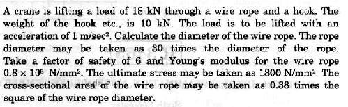
 Moments The crane in the image below looks unstable, as though it should topple over. There appears to be too much of the boom on the left-hand side of the tower. It doesn t fall because of the presence
EXAMPLES GEARS. page 1
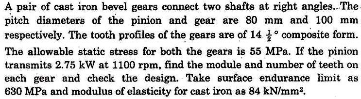
 (EXAMPLES GEARS) EXAMPLES GEARS Example 1: Shilds p. 76 A 20 full depth spur pinion is to trans mit 1.25 kw at 850 rpm. The pinion has 18 teeth. Determine the Lewis bending stress if the module is 2 and
MECHANICAL DRIVES 1 SPUR GEAR DRIVES LEARNING ACTIVITY PACKET BB502-XD06AEN
 MECHANICAL DRIVES 1 LEARNING ACTIVITY PACKET SPUR GEAR DRIVES BB502-XD06AEN LEARNING ACTIVITY PACKET 6 SPUR GEAR DRIVES INTRODUCTION This LAP will begin the study of the third type of adjacent shaft-to-shaft
BEVELGEAR. Competence and Performance.
 MS-Graessner GmbH & Co. KG THE GEAR COMPANY BEVELGEAR Competence and Performance General Advantages of Spiral, Hypoid and Zerol Bevel Gears High level of coverage due to the fact that several teeth are
GEAR GENERATION GEAR FORMING. Vipin K. Sharma
 GEAR GENERATION GEAR FORMING 1 GEAR MANUFACTURING Manufacturing of gears needs several processing operations in sequential stages depending upon the material and type of the gears and quality desired.
Gearless Power Transmission-Offset Parallel Shaft Coupling
 Gearless Power Transmission-Offset Parallel Shaft Coupling Mahantesh Tanodi 1, S. B. Yapalaparvi 2, Anand. C. Mattikalli 3, D. N. Inamdar 2, G. V. Chiniwalar 2 1 PG Scholar, Department of Mechanical Engineering,
The Available Solution CYCLO DRIVE. Gearmotors & Speed Reducers. Series
 The Available Solution CYCLO DRIVE Gearmotors & Speed Reducers 6000 Series WHAT DO YOU THINK OF THIS? THESE ARE THE ADVANTAGES OF THE NEWEST CYCLO, 6000 SERIES: More frame sizes, gear ratios and motor