SECTION 8 BEVEL GEARING
|
|
|
- Lambert Malone
- 5 years ago
- Views:
Transcription
1 SECTION 8 BEVEL GEARING For intersecting shafts, bevel gears offer a good means of transmitting motion and power. Most transmissions occur at right angles, Figure 8-1, but the shaft angle can be any value. Ratios up to 4:1 are common, although higher ratios are possible as well. 8.1 Development And Geometry Of Bevel Gears Bevel gears have tapered elements because they are generated and operate, in theory, on the surface of a sphere. Pitch diameters of mating bevel gears belong to frusta of cones, as shown in Figure 8-2a. In the full development on the surface of a sphere, a pair of meshed bevel gears are in conjugate engagement as shown in Figure 8-2b. 8.2 Bevel Gear Tooth Proportions Bevel gear teeth are proportioned in accordance with the standard system of tooth proportions used for spur gears. However, the pressure angle of all standard design bevel gears is limited to 20º. Pinions with a small number of teeth are enlarged automatically when the design follows the Gleason system. Since bevel-tooth elements are tapered, tooth dimensions and pitch diameter are referenced to the outer end (heel). Since the narrow end of the teeth (toe) vanishes at the pitch apex (center of reference generating sphere), there is a practical limit to the length (face) of a bevel gear. The geometry and identification of bevel gear parts is given in Figure 8-5. The crown gear, which is a bevel gear having the largest possible pitch angle (defined in Figure 8-3), is analogous to the rack of spur gearing, and is the basic tool for generating bevel gears. However, for practical reasons, the tooth form is not that of a spherical involute, and instead, the crown gear profile assumes a slightly simplified form. Although the deviation from a true spherical involute is minor, it results in a line-of-action having a figure-8 trace in its extreme extension; see Figure 8-4. This shape gives rise to the name octoid" for the tooth form of modern bevel gears. 356
2 8.3 Velocity Ratio The velocity ratio, i, can be derived from the ratio of several parameters: i = z 1 = d 1 = sinδ 1 (8-1) short face width sections, angularly displace one relative to the z 2 d 2 sinδ 2 other, and one has a spiral bevel gear. Well-designed spiral where: δ = pitch angle (see Figure 8-5) bevels have two or more teeth in contact at all times. The 8.4 Forms Of Bevel Teeth * overlapping tooth action transmits motion more smoothly and In the simplest design, the tooth elements are straight radial. quietly than with straight bevel gears. converging at the cone apex. However, it is possible to have the Zerol bevels (Figure 8-6d) have curved teeth similar to teeth curve along a spiral as they converge on the cone apex. those of the spiral bevels, but with zero spiral angle at the resulting in greater tooth overlap, analogous to the overlapping middle of the face width; and they have little end thrust. action of helical teeth. The result is a spiral bevel tooth. In Both spiral and Zerol gears can be cut on the same machines addition, there are other possible variations. One is the zerol with the same circular face-mill cutters or ground on the same bevel, which is a curved tooth having elements that start and grinding machines. Both are produced with localized tooth end on the same radial line. contact which can be controlled for length, width, and shape. Functionally, however. Zerol bevels are similar to the straight bevels and thus carry the same ratings. In fact, Zerols can be used in the place of straight bevels without mounting changes. Zerol bevels are widely employed in the aircraft industry, where ground-tooth precision gears are generally required. Most hypoid cutting machines can cut spiral bevel, Zerol or hypoid gears. Straight bevel gears come in two variations depending upon the fabrication equipment. All current Gleason straight bevel generators are of the Coniflex form which gives an almost imperceptible convexity to the tooth surfaces. Older machines produce true straight elements. See Figure 8-6a. Straight bevel gears are the simplest and most widely used type of bevel gears for the transmission of power and/or motion between intersecting shafts. Straight bevel gears are recommended: 1. When speeds are less than 300 meters/mm (1000 feet/ min - at higher speeds, straight bevel gears may be noisy. 2. When loads are light, or for high static loads when surface wear is not a critical factor. 3. When space, gear weight, and mountings are a premium. This includes planetary gear sets, where space does not permit the inclusion of rolling-element bearings. 8.5 Bevel Gear Calculations Let z 1 and z 2 be pinion and gear tooth numbers; shaft angle Σ and pitch cone angles δ 1 and δ 2 then: Generally, shaft angle Σ = 90º is most used. Other angles (Figure 8-7) are sometimes used. Then, it is called "bevel gear in nonright angle drive". The 90º case is called "bevel gear in right angle drive". When δ 1 = 90º, Equation (8-2) becomes: (8-2) Other forms of bevel gearing include the following: (8-3) Coniflex gears (Figure 8-6b) are produced by current Gleason straight bevel gear generating machines that crown the sides of the teeth in their lengthwise direction. The teeth, therefore, tolerate small amounts of misalignment in the assembly of the gears and some displacement of the gears under load without concentrating the tooth contact at the ends Miter gears are bevel gears with Σ = 90º and z 1 = z 2. Their of the teeth. Thus, for the operating conditions Coniflex gears speed ratio z 1 / z 2 = 1. They only change the direction of the are capable of transmitting larger loads than the predecessor shaft, but do not change the speed. Gleason straight bevel gears. Figure 8-8 depicts the meshing of bevel gears. The meshing Spiral bevels (Figure 8-6c) have curved oblique teeth whichmust be considered in pairs. It is because the pitch cone angles contact each other gradually and smoothly from one end to the other. Imagine cutting a straight bevel into an infinite number of The material in this section has been reprinted with the permission of McGraw Hill Book Co., Inc., New York, N.Y. from "Design of Bevel Gears by W. Coleman, Gear Design and Applications, N. Chironis, Editor, McGraw Hill, New York, N.Y. 1967, p. 57. δ 1 and δ 2 are restricted by the gear ratio z 1 / z 2 In the facial view, which is normal to the contact line of pitch cones, the meshing of bevel gears appears to be similar to the meshing of spur gears. 357
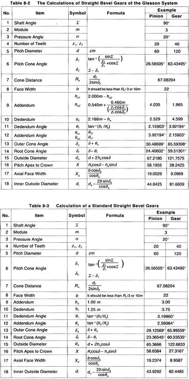
3 8.5.1 Gleason Straight Bevel Gears The straight bevel gear has straight teeth flanks which are along the surface of the pitch cone from the bottom to the apex. Straight bevel gears can be grouped into the Gleason type and the standard type. In this section, we discuss the Gleason straight bevel gear. The Gleason Company defined the tooth profile as: whole depth h = 2.188m; top clearance C a = 0.188m; and working depth h w = 2.000m. The characteristics are: Design specified profile shifted gears: In the Gleason system, the pinion is positive shifted and the gear is negative shifted. The reason is to distribute the proper strength between the two gears. Miter gears, thus, do not need any shifted tooth profile. The top clearance is designed to be parallel The outer cone elements of two paired bevel gears are parallel. That is to ensure that the top clearance along the whole tooth is the same. For the standard bevel gears, top clearance is variable. It is smaller at the toe and bigger at the heel. Table 8-1 shows the minimum number of teeth to prevent undercut in the Gleason system at the shaft angle S = 90º. Table 8-2 presents equations for designing straight bevel gears in the Gleason system. The meanings of the dimensions and angles are shown in Figure 8-9. All the equations in Table 8-2 can also be applied to bevel gears with any shaft angle. The straight bevel gear with crowning in the Gleason system is called a Coniflex gear. It is manufactured by a special Gleason "Coniflex" machine. It can successfully eliminate poor tooth wear due to improper mounting and assembly. The first characteristic of a Gleason straight bevel gear is its profile shifted tooth. From Figure 8-10, we can see the positive tooth profile shift in the pinion. The tooth thickness at the root diameter of a Gleason pinion is larger than that of a standard straight bevel gear. Table 8-1 The Minimum Numbers of Teeth to Prevent Undercut Pressure Angle 29/over (14.5º) 29 16/Over 20º (25º) 16 13/Over 13 Combination of Numbers of Teeth Z 1 Z 2 28/Over 27/Over 26/Over 25/Over /Over 17 14/Over 20 13/Over 30 24/Over Standard Straight Bevel Gears A bevel gear with no profile shifted tooth is a standard straight bevel gear. The applicable equations are in Table 8-3. These equations can also be applied to bevel gear sets with other than 90º shaft angle Gleason Spiral Bevel Gears A spiral bevel gear is one with a spiral tooth flank as in Figure The spiral is generally consistent with the curve of a cutter with the diameter d c The spiral angle β is the angle between a generatrix element of the pitch cone and the tooth flank. The spiral angle just at the tooth flank center is called central spiral angle β m In practice, spiral angle means central spiral angle. All equations in Table 8-6 are dedicated for the manufacturing method of Spread Blade or of Single Side from Gleason. If a gear is not cut per the Gleason system, the equations will be different from these. The tooth profile of a Gleason spiral bevel gear shown here has the whole depth h= 1.888m; top clearance C a = 0.188m; and working depth h w = 1.700m. These Gleason spiral bevel gears belong to a stub gear system. This is applicable to gears with m>2.1 Table 8-4 shows the minimum number of teeth to avoid undercut in the Gleason system with shaft angle Σ = 90º and pressure angle a n = 20º. If the number of teeth is less than 12, Table 8-5 is used to determine the gear sizes. All equations in Table 8-6 are also applicable to Gleason bevel gears with any shaft angle. A spiral bevel gear set requires matching of hands; left-hand and right-hand as a pair. 358
4 359
5 360
Spur Gears. Helical Gears. Bevel Gears. Worm Gears
 Spur s General: Spur gears are the most commonly used gear type. They are characterized by teeth which are perpendicular to the face of the gear. Spur gears are by far the most commonly available, and
11. GEAR TRANSMISSIONS
 11. GEAR TRANSMISSIONS 11.1. GENERAL CONSIDERATIONS Gears are one of the most important elements used in machinery. There are few mechanical devices that do not have the need to transmit power and motion
1.6 Features of common gears
 1.6 Features of common gears Chapter 1.2 covered briefly on types of gear. The main gear features are explained here. Helical gear Helical gear has characteristics of transferability of larger load, less
Part VII: Gear Systems: Analysis
 Part VII: Gear Systems: Analysis This section will review standard gear systems and will provide the basic tools to perform analysis on these systems. The areas covered in this section are: 1) Gears 101:
Catalog Q Conversion For those wishing to ease themselves into working with metric gears
 1.3.4 Conversion For those wishing to ease themselves into working with metric gears by looking at them in terms of familiar inch gearing relationships and mathematics, Table 1-5 is offered as a means
GEAR CONTENTS POWER TRANSMISSION GEAR TYPES OF GEARS NOMENCLATURE APPLICATIONS OF GEARS VELOCITY RATIO GEAR TRAINS EXAMPLE PROBLEMS AND QUESTIONS
 GEAR CONTENTS POWER TRANSMISSION GEAR TYPES OF GEARS NOMENCLATURE APPLICATIONS OF GEARS VELOCITY RATIO GEAR TRAINS EXAMPLE PROBLEMS AND QUESTIONS GEAR.. Power transmission is the movement of energy from
BEVELGEAR. Competence and Performance.
 BEVELGEAR Competence and Performance www.graessner.de General Advantages of Spiral, Hypoid and Zerol Bevel Gears High level of coverage due to the fact that several teeth are meshed simultaneously Resistant
Lecture (7) on. Gear Measurement. By Dr. Emad M. Saad. Industrial Engineering Dept. Faculty of Engineering. Fayoum University.
 on. Gear Measurement. By Dr. Emad M. Saad. Industrial Engineering Dept. Faculty of Engineering. Fayoum University.") 1 Lecture (7) on Gear Measurement Fayoum University By Dr. Emad M. Saad Industrial Engineering Dept. Faculty of Engineering Fayoum University Faculty of Engineering Industrial Engineering Dept. 2015-2016
1 Lecture (7) on Gear Measurement Fayoum University By Dr. Emad M. Saad Industrial Engineering Dept. Faculty of Engineering Fayoum University Faculty of Engineering Industrial Engineering Dept. 2015-2016
Tribology Aspects in Angular Transmission Systems
 Tribology Aspects in Angular Transmission Systems Part II Straight Bevel Gears Dr. Hermann Stadtfeld (This is the second of an eight-part series on the tribology aspects of angular gear drives. Each article
Figure 1.1 "Bevel and hypoid gears" "Modules" Figure / August 2011 Release 03/2011
 KISSsoft Tutorial 015: Bevel Gears KISSsoft AG - +41 55 254 20 50 Uetzikon 4 - +41 55 254 20 51 8634 Hombrechtikon - info@kisssoft. AG Switzerland - www. KISSsoft. AG KISSsoft Tutorial: Bevel Gears 1 Starting
ISO INTERNATIONAL STANDARD. Bevel and hypoid gear geometry. Géométrie des engrenages coniques et hypoïdes. First edition
 INTERNATIONAL STANDARD ISO 23509 First edition 2006-09-01 Bevel and hypoid gear geometry Géométrie des engrenages coniques et hypoïdes Reference number ISO 2006 Provläsningsexemplar / Preview PDF disclaimer
KISSsoft 03/2013 Tutorial 15
 KISSsoft 03/2013 Tutorial 15 Bevel gears KISSsoft AG Rosengartenstrasse 4 8608 Bubikon Switzerland Tel: +41 55 254 20 50 Fax: +41 55 254 20 51 info@kisssoft.ag www.kisssoft.ag Contents 1 Starting KISSsoft...
SECTION 4 SPUR GEAR CALCULATIONS
 Function of α, or invα, is known as involute function. Involute function is very important in gear design. Involute function values can be obtained from appropriate tables. With the 3.1 Contact Ratio center
Lecture 13 BEVEL GEARS
 Lecture 13 BEVEL GEARS CONTENTS 1. Bevel gear geometry and terminology 2. Bevel gear force analysis 3. Bending stress analysis 4. Contact stress analysis 5. Permissible bending fatigue stress 6. Permissible
Gear Tooth Geometry - This is determined primarily by pitch, depth and pressure angle
 Gear Tooth Geometry - This is determined primarily by pitch, depth and pressure angle Addendum: The radial distance between the top land and the pitch circle. Addendum Circle: The circle defining the outer
KISSsoft 03/2017 Tutorial 15
 KISSsoft 03/2017 Tutorial 15 Bevel gears KISSsoft AG Rosengartenstrasse 4 8608 Bubikon Switzerland Tel: +41 55 254 20 50 Fax: +41 55 254 20 51 info@kisssoft.ag www.kisssoft.ag Contents 1 Starting KISSsoft...
CH#13 Gears-General. Drive and Driven Gears 3/13/2018
 CH#13 Gears-General A toothed wheel that engages another toothed mechanism in order to change the speed or direction of transmitted motion The gear set transmits rotary motion and force. Gears are used
Metrology Prof. Dr Kanakuppi Sadashivappa Bapuji Institute of Engineering and Technology Davangere. Lecture 25 Introduction of Gears
 Metrology Prof. Dr Kanakuppi Sadashivappa Bapuji Institute of Engineering and Technology Davangere Lecture 25 Introduction of Gears I welcome you for the series of lecture on gear measurement and at module
The Basics of Gear Theory, Part 2
 The Basics of Gear Theory, Part 2 Hermann J. Stadtfeld Bevel Gears: By the Book Introduction (Chapter 1, Part 2) The first part of this publication series covered the general basics of involute gearing
Copyright Notice. Small Motor, Gearmotor and Control Handbook Copyright Bodine Electric Company. All rights reserved.
 Copyright Notice Small Motor, Gearmotor and Control Handbook Copyright 1993-2003 Bodine Electric Company. All rights reserved. Unauthorized duplication, distribution, or modification of this publication,
Chapter 8 Kinematics of Gears
 Chapter 8 Kinematics of Gears Gears! Gears are most often used in transmissions to convert an electric motor s high speed and low torque to a shaft s requirements for low speed high torque: Speed is easy
Bevel and hypoid gear geometry
 Provläsningsexemplar / Preview INTERNATIONAL STANDARD ISO 23509 Second edition 2016-11-15 Bevel and hypoid gear geometry Géométrie des engrenages coniques et hypoïdes Reference number ISO 2016 Provläsningsexemplar
BEVELGEAR. Competence and Performance.
 MS-Graessner GmbH & Co. KG THE GEAR COMPANY BEVELGEAR Competence and Performance General Advantages of Spiral, Hypoid and Zerol Bevel Gears High level of coverage due to the fact that several teeth are
12/6/2013 9:09 PM. Chapter 13. Gears General. Dr. Mohammad Suliman Abuhaiba, PE
 Chapter 13 Gears General 1 2 Chapter Outline 1. Types of Gears 2. Nomenclature 3. Conjugate Action 4. Involute Properties 5. Fundamentals 6. Contact Ratio 7. Interference 8. The Forming of Gear Teeth 9.
Chapter seven. Gears. Laith Batarseh
 Chapter seven Gears Laith Batarseh Gears are very important in power transmission between a drive rotor and driven rotor What are the functions of gears? - Transmit motion and torque (power) between shafts
1/2/2015 2:04 PM. Chapter 13. Gears General. Dr. Mohammad Suliman Abuhaiba, PE
 Chapter 13 Gears General 1 2 Chapter Outline 1. Types of Gears 2. Nomenclature 3. Conjugate Action 4. Involute Properties 5. Fundamentals 6. Contact Ratio 7. Interference 8. The Forming of Gear Teeth 9.
UNIT -I. Ans: They are specified by the no. of strands & the no. of wires in each strand.
 VETRI VINAYAHA COLLEGE OF ENGINEERING AND TECHNOLOGY, THOTTIAM, NAMAKKAL-621215. DEPARTMENT OF MECHANICAL ENGINEERING SIXTH SEMESTER / III YEAR ME6601 DESIGN OF TRANSMISSION SYSTEM (Regulation-2013) UNIT
INVOLUTE SPIRAL FACE COUPLINGS AND GEARS: DESIGN APPROACH AND MANUFACTURING TECHNIQUE
 УДК 621.9.015 Dr. Alexander L. Kapelevich, Stephen D. Korosec 38 INVOLUTE SPIRAL FACE COUPLINGS AND GEARS: DESIGN APPROACH AND MANUFACTURING TECHNIQUE This paper presents spiral face gears with an involute
What are the functions of gears? What is gear?
 8//0 hapter seven Laith atarseh are very important in power transmission between a drive rotor and driven rotor What are the functions of gears? - Transmit motion and torque (power) between shafts - Maintain
(POWER TRANSMISSION Methods)
") UNIT-5 (POWER TRANSMISSION Methods) It is a method by which you can transfer cyclic motion from one place to another or one pulley to another pulley. The ways by which we can transfer cyclic motion are:-
UNIT-5 (POWER TRANSMISSION Methods) It is a method by which you can transfer cyclic motion from one place to another or one pulley to another pulley. The ways by which we can transfer cyclic motion are:-
ME6601 DESIGN OF TRANSMISSION SYSTEMS
 SYED AMMAL ENGINEERING COLLEGE (Approved by the AICTE, New Delhi, Govt. of Tamilnadu and Affiliated to Anna University, Chennai) Established in 1998 - An ISO 9001:2008 Certified Institution Dr. E.M.Abdullah
Technology of Machine Tools
 PowerPoint to accompany Technology of Machine Tools 6 th Edition Krar Gill Smid Gear Cutting Unit 70 Copyright The McGraw-Hill Companies, Inc. Permission required for reproduction or display. 70-2 Objectives
Bevel Gears. Fig.(1) Bevel gears
 Bevel gears") Bevel Gears Bevel gears are cut on conical blanks to be used to transmit motion between intersecting shafts. The simplest bevel gear type is the straighttooth bevel gear or straight bevel gear as can be
Bevel Gears Bevel gears are cut on conical blanks to be used to transmit motion between intersecting shafts. The simplest bevel gear type is the straighttooth bevel gear or straight bevel gear as can be
Bevel Gears n A Textbook of Machine Design
 080 n A Textbook of Machine Design C H A P T E R 30 Bevel Gears. Introduction.. Classification of Bevel Gears. 3. Terms used in Bevel Gears. 4. Determination of Pitch Angle for Bevel Gears. 5. Proportions
DUDLEY'S" HANDBOOK OF PRACTICAL GEAR DESIGN AND MANUFACTURE. Stephen P. Radzevich
 Second Edition DUDLEY'S" HANDBOOK OF PRACTICAL GEAR DESIGN AND MANUFACTURE Stephen P. Radzevich LßP) CRC Press VV J Taylors Francis Group Boca Raton London New York CRC Press is an imprint of the Taylor
KINGS COLLEGE OF ENGINEERING DEPARTMENT OF MECHANICAL ENGINEERING
 KINGS COLLEGE OF ENGINEERING DEPARTMENT OF MECHANICAL ENGINEERING QUESTION BANK Sub Code/Name: ME 1352 DESIGN OF TRANSMISSION SYSTEMS Year/Sem: III / VI UNIT-I (Design of transmission systems for flexible
Finite element analysis of profile modified spur gear
 Finite element analysis of profile modified spur gear Sagar Gaur Mechanical Engineering Department, Institute of Technology, YashluvVirwani Mechanical Engineering Department, Institute of Technology, Rudresh
Tribology Aspects in Angular Transmission Systems
 Tribology Aspects in Angular Transmission Systems Part VI: Beveloid & Hypoloid Gears Dr. Hermann Stadtfeld (This article is part six of an eight-part series on the tribology aspects of angular gear drives.
Instantaneous Centre Method
 Instantaneous Centre Method The combined motion of rotation and translation of the link AB may be assumed to be a motion of pure rotation about some centre I, known as the instantaneous centre of rotation.
 DEPARTMENT OF MECHANICAL ENGINEERING Subject code: ME6601 Subject Name: DESIGN OF TRANSMISSION SYSTEMS UNIT-I DESIGN OF TRANSMISSION SYSTEMS FOR FLEXIBLE ELEMENTS 1. What is the effect of centre distance
Basic Fundamentals of Gear Drives
 Basic Fundamentals of Gear Drives Course No: M06-031 Credit: 6 PDH A. Bhatia Continuing Education and Development, Inc. 9 Greyridge Farm Court Stony Point, NY 10980 P: (877) 322-5800 F: (877) 322-4774
Introduction. Kinematics and Dynamics of Machines. Involute profile. 7. Gears
 Introduction The kinematic function of gears is to transfer rotational motion from one shaft to another Kinematics and Dynamics of Machines 7. Gears Since these shafts may be parallel, perpendicular, or
Bibliography. [1] Buckingham, Earle: "Analytical Mechanics of Gears", McGraw-Hill, New York, 1949, and republished by Dover, New York, 1963.
![Bibliography. [1] Buckingham, Earle: Analytical Mechanics of Gears, McGraw-Hill, New York, 1949, and republished by Dover, New York, 1963.](/thumbs/87/96820687.jpg "Bibliography. [1] Buckingham, Earle: Analytical Mechanics of Gears, McGraw-Hill, New York, 1949, and republished by Dover, New York, 1963.") Bibliography The first five references listed are books on gearing. Some of them deal not only with the geometry, but also with many other aspects of gearing. However, the books are included in this bibliography
Bibliography The first five references listed are books on gearing. Some of them deal not only with the geometry, but also with many other aspects of gearing. However, the books are included in this bibliography
Gear Drives. A third gear added to the system will rotate in the same direction as the drive gear Equal diameters = Equal number of teeth = Same speed
 Gear Drive Systems Gear Drives Gear Drive: Synchronous mechanical drive that uses gears to transfer power Gear: A toothed wheel that meshes with other toothed wheels to transfer rotational power Pinion
1.8 Rack shift of the gear
 1.8 Rack shift of the gear Undercut When Number of teeth is belo minimum as shon in Fig. 3, part of dedendum is no longer an Involute curve but ill look like a shape scooped out by cutter tool. Refer to
MMS Spiral Miter Gears. SMS Spiral Miter Gears. m1 ~ 8 Page 268. SAM Angular Miter Gears. m1 ~ 4 Page 278. Direction of Spiral ( R )
") Miter Spur MMSG Ground Spiral Miter SMSG Ground Spiral Miter MMSA MMSB Finished Bore Spiral Miter MMS Spiral Miter SMS Spiral Miter SMZG Ground Zerol Miter SMA SMB SMC Finished Bore Miter Series Series
Miter Spur MMSG Ground Spiral Miter SMSG Ground Spiral Miter MMSA MMSB Finished Bore Spiral Miter MMS Spiral Miter SMS Spiral Miter SMZG Ground Zerol Miter SMA SMB SMC Finished Bore Miter Series Series
CHAPTER 5 PREVENTION OF TOOTH DAMAGE IN HELICAL GEAR BY PROFILE MODIFICATION
 90 CHAPTER 5 PREVENTION OF TOOTH DAMAGE IN HELICAL GEAR BY PROFILE MODIFICATION 5.1 INTRODUCTION In any gear drive the absolute and the relative transmission error variations normally increases with an
The Basics of Gear Theory
 technical The Basics of Gear Theory Hermann J. Stadtfeld Bevel Gears: By the Book Beginning with our June Issue, Gear Technology is pleased to present a series of full-length chapters excerpted from Dr.
Determination and improvement of bevel gear efficiency by means of loaded TCA
 Determination and improvement of bevel gear efficiency by means of loaded TCA Dr. J. Thomas, Dr. C. Wirth, ZG GmbH, Germany Abstract Bevel and hypoid gears are widely used in automotive and industrial
Introduction to Gear Design
 Introduction to Gear Design Course No: M03-016 Credit: 3 PDH Robert P. Tata, P.E. Continuing Education and Development, Inc. 9 Greyridge Farm Court Stony Point, NY 10980 P: (877) 322-5800 F: (877) 322-4774
GEARING. Theory of. Stephen. Kinetics, Geometry, and Synthesis. P. Radzevich. /Ov CRC Press yc*** J Taylor& Francis Croup Boca Raton
 Theory of GEARING Kinetics, Geometry, and Synthesis Stephen P. Radzevich /Ov CRC Press yc*** J Taylor& Francis Croup Boca Raton London New York CRC Press is an imprint of the Taylor & Francis Group, an
Ernie Reiter and Irving Laskin
 F I N E P I T C H, P L A S T I C FA C E G E A R S : Design Ernie Reiter and Irving Laskin Ernie Reiter is a consultant specializing in the design of gears and geared products. He has authored modern software
1.7 Backlash. Summary of the backlash is play or clearance between one pair of gear. Fig. 17 Backlash
 1.7 Backlash Summary of the backlash is play or clearance between one pair of gear. Fig. 17 Backlash Great care is taken to produce the gear with zero deviation. However we are unable to completely eliminate
Chapter 3. Transmission Components
 Chapter 3. Transmission Components The difference between machine design and structure design An important design problem in a mechanical system is how to transmit and convert power to achieve required
General gear terms and definitions. Trantorque 48 DP. Steel and Brass
 General gear terms and definitions 317 Spur and Helical Gears: Formulae and definitions Helical Gear Spur Gear Term Definition formulae formulae 318 Spur and Helical Gears: Formulae and definitions Helical
Design and Fabrication of Shaft Drive for two Wheelers
 International OPEN ACCESS Journal Of Modern Engineering Research (IJMER) Design and Fabrication of Shaft Drive for two Wheelers K.Vinoth Kumar 1, Kari Naga Nikhil, Kakollu Manoj Kumar, Kaza Sai Sravan
Program Internal Gear Set Profile Shift Coefficients With Zero Backlash Introduction
 Program 60-107 Internal Gear Set Profile Shift Coefficients With Zero Backlash Introduction The purpose of this model is to provide data for a gear set when the tooth thickness and/or the center distance
Thermal Analysis of Helical and Spiral Gear Train
 International Journal for Ignited Minds (IJIMIINDS) Thermal Analysis of Helical and Spiral Gear Train Dr. D V Ghewade a, S S Nagarale b & A N Pandav c a Principal, Department of Mechanical, GENESIS, Top-Kolhapur,
Quindos the Ultimate Software package for Gears, Gear Tools and other Special Applications
 Quindos the Ultimate Software package for Gears, Gear Tools and other Special Applications Quindos gear packages Gearings Cylindrical Gear Unknown Gear Involute & Lead Master Straight Bevel Gear Spiral
Spiroid High Torque Skew Axis Gearing A TECHNICAL PRIMER F. EVERTZ, M. GANGIREDDY, B. MORK, T. PORTER & A. QUIST
 2016 Spiroid High Torque Skew Axis Gearing A TECHNICAL PRIMER F. EVERTZ, M. GANGIREDDY, B. MORK, T. PORTER & A. QUIST Table of Contents INTRODUCTION PAGE 02 SPIROID GEAR SET CHARACTERISTICS PAGE 03 BASIC
Involute Simulation Softwares Inc.
 Involute Simulation Softwares Inc. Updates / Recent changes Claude Gosselin, Ph.D., P.Eng. 2012-2017 www.hygears.com 1 Updates Contents HyGEARS update 29 November 2017 - Build 405.90-462... 3 HyGEARS and
Sheet 1 Variable loading
 Sheet 1 Variable loading 1. Estimate S e for the following materials: a. AISI 1020 CD steel. b. AISI 1080 HR steel. c. 2024 T3 aluminum. d. AISI 4340 steel heat-treated to a tensile strength of 1700 MPa.
Different types of gears. Spur gears. Idler gears. Worm gears. Bevel gears. Belts & Pulleys
 GEARS Robot Gears By using different gear diameters, you can exchange between rotational (or translation) velocity and torque. by looking at the motor datasheet you can determine the output velocity and
T25 T25 T25 T27 T27 T28 T28 T28 T28 T29 T29 T29 T31 T37 T37 T38 T T T48
 1.0 INTRODUCTION 2.0 BASIC GEOMETRY OF SPUR GEARS 2.1 Basic Spur Gear Geometry 2.2 The Law of Gearing 2.3 The Involute Curve 2.4 Pitch Circles 2.5 Pitch 2.5.1 Circular Pitch 2.5.2 Diametral Pitch 2.5.3
Session #3 Gears: Force Transmission & Gear Trains. Dan Frey
 Session #3 Gears: Force Transmission & Gear Trains Dan Frey Today s Agenda Pass out second reading packet Pass out loaner laptops Introduce project teams Gears Force Transmission Gear Trains Survey HW
Bevel Gears. Catalog Number of KHK Stock Gears. Bevel Gears M BS G R. Gears. Spur. Helical. Gears. Internal. Gears. Racks. CP Racks.
 MHP High-Ratio Hypoid Ground Spiral G Ground Spiral 15 ~ 200 2 m1, 1.5 Page 456 m2 ~ 4 Page 458 m2 ~ 4 Page 460 Spur MBSA MBSB Finished Bore Spiral Spiral 1.5 ~ 4 SBZG Ground Zerol 1.5, 2 Helical m2 ~
ANALYSIS OF SURFACE CONTACT STRESS FOR A SPUR GEAR OF MATERIAL STEEL 15NI2CR1MO28
 ANALYSIS OF SURFACE CONTACT STRESS FOR A SPUR GEAR OF MATERIAL STEEL 15NI2CR1MO28 D. S. Balaji, S. Prabhakaran and J. Harish Kumar Department of Mechanical Engineering, Chennai, India E-Mail: balajimailer@gmail.com
Gear Measurement. Lecture (7) Mechanical Measurements
 Mechanical Measurements") 18 3. Gear profile checking 2. Involute measuring machine In this method the gear is held on a mandrel and circular disc of same diameter as the base circle of gear for the measurement is fixed on the
18 3. Gear profile checking 2. Involute measuring machine In this method the gear is held on a mandrel and circular disc of same diameter as the base circle of gear for the measurement is fixed on the
MANUFACTURING OF GEAR BOXES
 Profile No.: 29 NIC Code: 29301 MANUFACTURING OF GEAR BOXES 1. INTRODUCTION: Gears play a prominent role in mechanical power transmission. A gear or cogwheel is a rotating machine part having cut teeth,
Engineering Information
 Engineering nformation Gear Nomenclature ADDENDUM (a) is the height by which a tooth projects beyond the pitch circle or pitch line. BASE DAMETER (D b ) is the diameter of the base cylinder from which
LAPPING OR GRINDING? WHICH TECHNOLOGY IS THE RIGHT CHOICE IN THE AGE OF INDUSTRY 4.0?
 LAPPING OR GRINDING? WHICH TECHNOLOGY IS THE RIGHT CHOICE IN THE AGE OF INDUSTRY 4.0? Bevel gear transmissions for the automotive industry are subject to extremely stringent requirements. They must be
we will learn how to conduct force and torque analysis on gears in order to calculate bearing
 8.1 Introduction to Gears Gears are used to transmit motion and torque from one shaft to another. In this section we will discuss the kinematics of gears; that is, the motion relationships between gears.
Therefore, it is the general practice to test the tooth contact and backlash with a tester. Figure 19-5 shows the ideal contact for a worm gear mesh.
 19. Surface Contact Of Worm And Worm Gear There is no specific Japanese standard concerning worm gearing, except for some specifications regarding surface contact in JIS B 1741. Therefore, it is the general
Effect of Geometry Factor I & J Factor Multipliers in the performance of Helical Gears
 Effect of Geometry Factor I & J Factor Multipliers in the performance of Helical Gears 1 Amit D. Modi, 2 Manan B. Raval, 1 Lecturer, 2 Lecturer, 1 Department of Mechanical Engineering, 2 Department of
1. (a) Discuss various types of Kinematic links with examples. (b) Explain different types of constrained motions with examples.
 Discuss various types of Kinematic links with examples. (b) Explain different types of constrained motions with examples.") Code No: RR310304 Set No. 1 III B.Tech I Semester Supplementary Examinations, February 2007 KINEMATICS OF MACHINERY ( Common to Mechanical Engineering, Mechatronics and Production Engineering) Time: 3
Code No: RR310304 Set No. 1 III B.Tech I Semester Supplementary Examinations, February 2007 KINEMATICS OF MACHINERY ( Common to Mechanical Engineering, Mechatronics and Production Engineering) Time: 3
Design of Helical Gear and Analysis on Gear Tooth
 Design of Helical Gear and Analysis on Gear Tooth Indrale Ratnadeep Ramesh Rao M.Tech Student ABSTRACT Gears are mainly used to transmit the power in mechanical power transmission systems. These gears
Gear Engineering Data. Spur Gear Gear Formulas Drive Selection Horsepower and Torque Tables
 Engineering Gear Engineering Data Spur Gear Gear Formulas Drive Selection Horsepower and Torque Tables G-79 Gear Selection Stock Spur Gear Drive Selection When designing a stock gear drive using the horsepower
A comparison of the gear calculation process according to Swedish and American textbooks for higher education
 World Transactions on Engineering and Technology Education Vol.6, No.1, 2007 2007 UICEE A comparison of the gear calculation process according to Swedish and American textbooks for higher education Samir
10.2 Calculation for Bevel gear strength
 10. Calculation for Bevel gear strength Calculation formula of Bending strength for Bevel gear JGMA 403-01 (1976) Calculation formula of Surface durability (Pitting resistance) for Bevel gear JGMA 404-01
Gearheads H-51. Gearheads for AC Motors H-51
 Technical Reference H-51 for AC Since AC motor gearheads are used continuously, primarily for transmitting power, they are designed with priority on ensuring high permissible torque, long life, noise reduction
Advantages and Disadvantages of Rolling Contact Bearings Over Sliding Contact Bearings
 Advantages and Disadvantages of Rolling Contact Bearings Over Sliding Contact Bearings Advantages 1. Low starting and running friction except at very high speeds. 2. Ability to withstand momentary shock
AN OPTIMAL PROFILE AND LEAD MODIFICATION IN CYLINDRICAL GEAR TOOTH BY REDUCING THE LOAD DISTRIBUTION FACTOR
 AN OPTIMAL PROFILE AND LEAD MODIFICATION IN CYLINDRICAL GEAR TOOTH BY REDUCING THE LOAD DISTRIBUTION FACTOR Balasubramanian Narayanan Department of Production Engineering, Sathyabama University, Chennai,
2. a) What is pantograph? What are its uses? b) Prove that the peaucellier mechanism generates a straight-line motion. (5M+10M)
 What is pantograph? What are its uses? b) Prove that the peaucellier mechanism generates a straight-line motion. (5M+10M)") Code No: R22032 R10 SET - 1 1. a) Define the following terms? i) Link ii) Kinematic pair iii) Degrees of freedom b) What are the inversions of double slider crank chain? Describe any two with neat sketches.
Code No: R22032 R10 SET - 1 1. a) Define the following terms? i) Link ii) Kinematic pair iii) Degrees of freedom b) What are the inversions of double slider crank chain? Describe any two with neat sketches.
Metric Standards Worldwide Japanese Metric Standards In This Text
 ELEMENTS OF METRIC GEAR TECHNOLOGY Table of Contents Page SECTION 1 INTRODUCTION TO METRIC GEARS 329 1.1 Comparison Of Metric Gears With American Inch Gears 329 1.1.1 1.1.2 1.1.3 Comparison of Basic Racks
50 g 50 e g ars e o ars lut o i lut on o s n.c s o.c m o
 50 gearsolutions.com Analysis and Optimization of Asymmetric Epicyclic Gears By Alexander L. Kapelevich Following the Direct Gear Design approach to asymmetric epicyclic gear stages with singular and compound
BRCM COLLEGE OF ENGINEERING & TECHNOLOGY BAHAL, BHIWANI Practical Experiment Instructions Sheet
 BRCM COLLEGE OF KOM ME- 212 F KINEMATICS OF MACHINES LAB BRANCH-ME List of Experiments : 1. To study various types of Kinematic links, pairs, chains and Mechanisms. 2. To study inversions of 4 Bar Mechanisms,
GEARBOXES. Gearboxes. Gearboxes. Gearbox is a mechanical device utilized to increase the output torque or change
 GEARBOXES Gearboxes Gearboxes Gearbox is a mechanical device utilized to increase the output torque or change the speed of a motor. The motor's shaft is attached to one end of the gearbox and through the
CHAPTER 3 page 35 PRINCIPLES OF GEAR-TOOTH GENERATION. .1 Angular Velocity Ratio
 CHAPTER 1 page 1..., ATURE, NOTATION AND CONVENTIONS TYPES OF GEAR 1.1 Spur 1.2 Helical 1.3 Double-Helical 1.4 Crossed Helical 1.5 Conical Involute 1.6 Bevel 1.7 Spiral Bevel 1.8 Hypoid 1.9 Worm NOMENCLATURE
o f Tip Relief on Transmission
 E v a l u a t i o n o f M e t h o d s f o r C a l c u l a t i n g E f f e c t s o f Tip Relief on Transmission E r r o r, N o i s e a n d S t r e s s i n L o a d e d S p u r G e a r s Dr. David Palmer
STATIC ANALYSIS ON BEVEL GEAR USING STRUCTURAL STEEL, GRAY CAST IRON, AND STAINLESS STEEL
 STATIC ANALYSIS ON BEVEL GEAR USING STRUCTURAL STEEL, GRAY CAST IRON, AND STAINLESS STEEL Prateek Srivastava 1, Rishabh 2, Zubair Irshad 3, Pankaj Kumar Singh 4 Graduate Students Mechanical Engineering,
Available in July 2010
 Available in July 2010 SGFD/SGFK/SGCPFD Ground acks m0.5~ 18 items engths : 0, 0 and 1000mm CP5~20 8 items engths : 0 and 1000mm The product line-up for the popular J-Series has expanded! Quick-touse Ground
Internal Gears. No. of teeth (60) Module (1) Others (Ring Gear) Type (Internal Gear) Material (S45C)
 Module (1) Others (Ring Gear) Type (Internal Gear) Material (S45C)") ph: (410)8-10 (0)68-180 fx: (410)8-142 (0)872-929 rfq form: http://mdmetric.com/rfq.htm Internal Internal Miter CP Racks & Pinions Racks Helical Spur SI Steel Internal SIR Steel Ring m0. ~ Page 184 m2
ph: (410)8-10 (0)68-180 fx: (410)8-142 (0)872-929 rfq form: http://mdmetric.com/rfq.htm Internal Internal Miter CP Racks & Pinions Racks Helical Spur SI Steel Internal SIR Steel Ring m0. ~ Page 184 m2
Modeling of the kinematic geometry of spur gears using matlab
 MATEC Web of Conferences 153, 03004 (018) ICMME 017 https://doi.org/10.1051/matecconf/01815303004 Modeling of the kinematic geometry of spur gears using matlab 1 Peter I. Anakhu, 1 Abiodun A. Abioye, 1
TECHNOLOGY MECHANISMS
 TECHNOLOGY MECHANISMS 3º ESO IES CHAN DO MONTE URTAZA 1 WHAT IS A MECHANISM? Mechanism are devices that have been designed to make jobs easier. They all have certain things in common: They involve some
ANALYSIS OF SPUR GEAR GEOMETRY AND STRENGTH WITH KISSSOFT SOFTWARE
 ANALYSIS OF SPUR GEAR GEOMETRY AND STRENGTH WITH KISSSOFT SOFTWARE Ashwini Gaikwad 1, Rajaram Shinde 2 1,2 Automobile Engineering Department, Rajarambapu Institute of Technology, Sakharale, Dist. Sangli,
The Geometry of Involute Gears
 The Geometry of Involute Gears J.R. Colbourne The Geometry of Involute Gears With 217 Illustrations Springer-Verlag New York Berlin Heidelberg London Paris Tokyo J.R. Colbourne Department of Mechanical
GEAR NOISE REDUCTION BY NEW APPROACHES IN GEAR FINISHING PROCESSES
 GEAR NOISE REDUCTION BY NEW APPROACHES IN GEAR FINISHING PROCESSES Nikam Akshay 1, Patil Shubham 2, Pathak Mayur 3, Pattewar Vitthal 4, Rawanpalle Mangesh 5 1,2,3,4,5 Department of Mechanical Engineering,
Mechanotechnology N3 Lecturer s Guide
 Mechanotechnology N3 Lecturer s Guide ISBN: 978-1-4308-0617-2 R Cameron & LL Maraschin This Lecturer s Guide accompanies the following Student s Book: Title: Mechanotechnology N3 Author: R Cameron & LL
MECHANICAL DRIVES 1 SPUR GEAR DRIVES LEARNING ACTIVITY PACKET BB502-XD06AEN
 MECHANICAL DRIVES 1 LEARNING ACTIVITY PACKET SPUR GEAR DRIVES BB502-XD06AEN LEARNING ACTIVITY PACKET 6 SPUR GEAR DRIVES INTRODUCTION This LAP will begin the study of the third type of adjacent shaft-to-shaft
St.MARTIN S ENGINEERING COLLEGE Dhulapally, Secunderabad
 St.MARTIN S ENGINEERING COLLEGE Dhulapally, Secunderabad-500 014 Subject: Kinematics of Machines Class : MECH-II Group A (Short Answer Questions) UNIT-I 1 Define link, kinematic pair. 2 Define mechanism