Lecture 13 BEVEL GEARS
|
|
|
- Mitchell Walters
- 5 years ago
- Views:
Transcription

1 Lecture 13 BEVEL GEARS CONTENTS 1. Bevel gear geometry and terminology 2. Bevel gear force analysis 3. Bending stress analysis 4. Contact stress analysis 5. Permissible bending fatigue stress 6. Permissible contact fatigue stress BEVEL GEARS Bevel gears transmit power between two intersecting shafts at any angle or non- intersecting shafts. They are classified as straight and spiral tooth bevel and hypoid gears in Fig.1
2 BEVEL GEARS GEOMETRY AND TERMINOLOGY When intersecting Shafts are connected by gears, the pitch cones (analogous to the pitch cylinders of spur and helical gears) are tangent along an element, with their apexes at the intersection of the shafts Fig.2. BEVEL GEARS GEOMETRY AND TERMINOLOGY The size and shape of the teeth are defined at the large end, where they intersect the back cones. Pitch cone and back cone elements are perpendicular. The tooth profiles resemble those of Spur gears having pitch radii equal to the developed back cone radii r bg and r bp, Fig. 3.

3 2πrb1 Z1 2πrb2 Z2 Z v1 = = (1) & Z v2 = = (2) p cosγ1 p cosγ2 where Z v is called the virtual number of teeth, p is the circular pitch of both the imaginary spur gears and the bevel gears. Z 1 and Z 2 are the number of teeth on the pinion and gear, γ and 1 γ2 are the pitch cone angles of pinion and gears. It is a practice to characterize the size and shape of bevel gear teeth as those of an imaginary spur gear appearing on the developed back cone corresponding to Tredgold s approximation. a) Bevel gear teeth are inherently noninterchangeable. b) The working depth of the teeth is usually 2m, the same as for standard spur and helical gears, but the bevel pinion is designed with the larger addendum ( 0.7 working depth). c) This avoids interference and results in stronger pinion teeth. It also increases the contact ratio. d) The gear addendum varies from 1m for a gear ratio of 1, to 0.54 m for ratios of 6.8 and greater.
 The Fig.")
4 The gear ratio can be determined from the number of teeth, the pitch diameters, or the pitch cone angles: Gear ratio i : ω n Z d i = = = = = tan γ 2 = cot γ1 (3) ω2 n2 Z1 d1 Accepted practice usually imposes two limits on the face width L b 10m and b 3 Where L is the cone distance. Smaller of the two is chosen for design. (4) The Fig.4 illustrates the measurement of the spiral angle ψ of a spiral bevel gear. Bevel gears most commonly have a pressure angle of 20 o, and spiral bevels usually have a spiral angle ψ of 35 o.

5 Fig.5 The Fig.5 on the right illustrates Zerol bevel gears, which are having curved teeth like spiral bevels. But they have a zero spiral angle.

6 DIFFERENT TYPES OF BEVEL GEARS BEVEL GEARS FORCE ANALYSIS
7
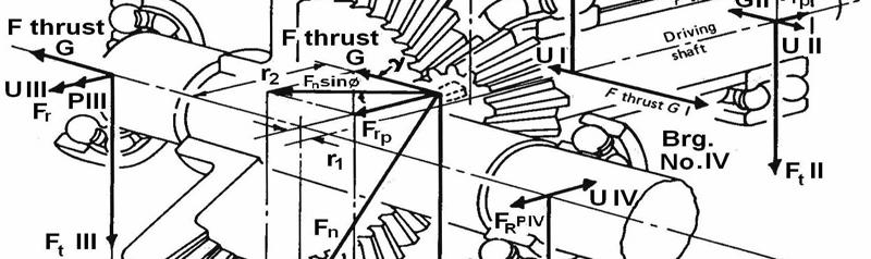
8 In the Fig.10, the resolution of resultant tooth force F n into its tangential (torque producing), radial (separating), and axial (thrust) components, is designated F t, F r and F a, respectively. An auxiliary view is needed to show the true length of the vector representing resultant force F n (which is normal to the tooth profile). Resultant force F n is shown applied to the tooth at the pitch cone surface and midway along tooth width b. It is also assumed that load is uniformly distributed along tooth width, despite the fact that the tooth width is larger at the outer end. dav = d bsin γ (5) πd n 6000 av V av = (6) 1000W F t = (7) v av Where V av is in meters per second, d av is in meters, n is in revolutions per minute, F t is in Newtons, and W is power in kilo Watts. Fn = F t /cos φ (8) Fr = Fncosγ = Ft tanφ cos γ (9) F = F sin γ = F tanφ sin γ (10) a n t
9 For spiral bevel gear Ft F r = ( tanφn cos ψ cos γ sinψ sin γ) (11) Fa = F t ( tanφn sin γ ± sinψcos γ) (12) Where or ± is used in the preceding equation, the upper sign applies to a driving pinion with right-hand spiral rotating clockwise as viewed from its large end and to a driving pinion with left-hand spiral rotating counter clock-wise when viewed from its large end. The lower sign applies to a left-hand driving pinion rotating clockwise and to a driving pinion rotating counter clockwise. Similar to helical gears, φ n is the pressure angle normal measured in a plane normal to the tooth. BEVEL GEARS TOOTH BENDING STRESS The equation for bevel gear bending stress is the same as for spur gears: Ft σb = KvKoK m (13) bmj Where, F t =Tangential load in Newtons m = module at the large end of the tooth in mm b = Face width in mm J = Geometry form factor based on virtual number of teeth, Fig. 13 & 14. K v = Velocity factor, from Fig. 15. K o = Overload factor, Table 1. K m = Mounting factor, depending on whether gears are straddle mounted (between two bearings) or overhung (outboard of both bearings), and on the degree of mounting rigidity. Table 2.


10 BEVEL GEARS GEOMETRY FACTOR J FOR STRAIGHT BEVEL GEARS BEVEL GEARS GEOMETRY FACTOR J FOR SPIRAL BEVEL GEARS
11 BEVEL GEARS DYNAMIC LOAD FACTOR K V BEVEL GEARS OVER LOAD FACTOR K o Table 1 -Overload factor K o Driven Machinery Source of power Uniform Moderate Shock Heavy Shock Uniform Light shock Medium shock
12 BEVEL GEARS MOUNTING FACTOR K m TABLE 2 BEVEL GEARS PERMISSIBLE TOOTH BENDING STRESS (AGMA) Fatigue strength of the material is given by: σ e = σ e k L k v k s k r k T k f k m (14) Where, σ e endurance limit of rotating-beam specimen k L = load factor, = 1.0 for bending loads k v = size factor, = 1.0 for m < 5 mm and = 0.85 for m > 5 mm k s = surface factor, is taken from Fig. 16 based on the ultimate strength of the material and for cut, shaved, and ground gears. k r = reliability factor given in Table 3. k T = temperature factor, = 1 for T 120 o C more than 120 o C, k T < 1 to be taken from AGMA standards
13 BEVEL GEARS SURFACE FACTOR k s BEVEL GEARS RELIABILITY FACTOR k R k f = fatigue stress concentration factor. Since this factor is included in J factor, its value is taken as 1. k m = Factor for miscellaneous effects. For idler gears subjected to two way bending, = 1. For other gears subjected to one way bending, the value is taken from the Fig.17. Use k m = 1.33 for σ ut less than 1.4 GPa.
14 Permissible bending stress σe [σ b ] = (15) s Hence the design equation from bending consideration is : σ b [ σ b ] (16) BEVEL GEARS SURFACE FATIGUE STRESS Bevel gear surface fatigue stress can be calculated as for spur gears, with only two modifications. Ft σ H=Cp KVKoK m (17) bdi BEVEL GEARS CONTACT STRESS C p values of 1.23 times the values given in the table are taken to account for a somewhat more localized contact area than spur gears.

15 BEVEL GEARS GEOMETRY FACTOR I FOR STRAIGHT BEVEL GEAR

16 BEVEL GEARS GEOMETRY FACTOR I FOR SPIRAL BEVEL GEAR BEVEL GEARS DYNAMIC LOAD FACTOR K v
17 BEVEL GEARS OVER LOAD FACTOR K o Table 5 -Overload factor K o Driven Machinery Source of power Uniform Moderate Shock Heavy Shock Uniform Light shock Medium shock BEVEL GEARS MOUNTING FACTOR K m TABLE 6 BEVEL GEARS SURFACE FATIGUE STRENGTH Surface fatigue strength of the material is given by: σ sf = σ sf K L K H K R K T (18) Where σ sf = surface fatigue strength of the material given in Table 7 K L = Life factor given in Fig. 21
18 BEVEL GEARS SURFACE FATIGUE STRENGTH, LIFE FACTOR KL

19 K H = Hardness ratio factor, K the Brinell hardness of the pinion by Brinell hardness of the Gear. Given in Fig.22. K H = 1.0 for K < 1.2 K R = Reliability factor, given in Table 8. BEVEL GEARS SURFACE FATIGUE STRENGTH, HARDNESS FACTOR K H Table 8. Reliability factor K R Reliability (%) K R
20 K T = temperature factor, = 1 for T 120 o C based on Lubricant temperature. Above 120 o C, it is less than 1 to be taken from AGMA standards. BEVEL GEARS ALLOWABLE SURFACE FATIGUE STRESS (AGMA) Allowable surface fatigue stress for design is given by [ σ H ] = σ Sf / s (19) Factor of safety s = 1.1 to 1.5 Hence Design equation is: σ H [ σ H ] (20)
Bevel Gears. Fig.(1) Bevel gears
 Bevel gears") Bevel Gears Bevel gears are cut on conical blanks to be used to transmit motion between intersecting shafts. The simplest bevel gear type is the straighttooth bevel gear or straight bevel gear as can be
Bevel Gears Bevel gears are cut on conical blanks to be used to transmit motion between intersecting shafts. The simplest bevel gear type is the straighttooth bevel gear or straight bevel gear as can be
Power transmission. Components used to transmit power: gears, belt, clutch and brakes. Gear (Stresses) act on the tooth Lewis formula and AGMA
 act on the tooth Lewis formula and AGMA") 1 Power transmission Components used to transmit power: gears, belt, clutch and brakes. Failure Types Gear (Stresses) Bending: resulted from bending stress. t act on the tooth Lewis formula and AGMA Pitting:
1 Power transmission Components used to transmit power: gears, belt, clutch and brakes. Failure Types Gear (Stresses) Bending: resulted from bending stress. t act on the tooth Lewis formula and AGMA Pitting:
1/2/2015 2:04 PM. Chapter 13. Gears General. Dr. Mohammad Suliman Abuhaiba, PE
 Chapter 13 Gears General 1 2 Chapter Outline 1. Types of Gears 2. Nomenclature 3. Conjugate Action 4. Involute Properties 5. Fundamentals 6. Contact Ratio 7. Interference 8. The Forming of Gear Teeth 9.
Bevel Gears n A Textbook of Machine Design
 080 n A Textbook of Machine Design C H A P T E R 30 Bevel Gears. Introduction.. Classification of Bevel Gears. 3. Terms used in Bevel Gears. 4. Determination of Pitch Angle for Bevel Gears. 5. Proportions
12/6/2013 9:09 PM. Chapter 13. Gears General. Dr. Mohammad Suliman Abuhaiba, PE
 Chapter 13 Gears General 1 2 Chapter Outline 1. Types of Gears 2. Nomenclature 3. Conjugate Action 4. Involute Properties 5. Fundamentals 6. Contact Ratio 7. Interference 8. The Forming of Gear Teeth 9.
SECTION 8 BEVEL GEARING
 SECTION 8 BEVEL GEARING For intersecting shafts, bevel gears offer a good means of transmitting motion and power. Most transmissions occur at right angles, Figure 8-1, but the shaft angle can be any value.
Part VII: Gear Systems: Analysis
 Part VII: Gear Systems: Analysis This section will review standard gear systems and will provide the basic tools to perform analysis on these systems. The areas covered in this section are: 1) Gears 101:
Effect of Geometry Factor I & J Factor Multipliers in the performance of Helical Gears
 Effect of Geometry Factor I & J Factor Multipliers in the performance of Helical Gears 1 Amit D. Modi, 2 Manan B. Raval, 1 Lecturer, 2 Lecturer, 1 Department of Mechanical Engineering, 2 Department of
Lecture (7) on. Gear Measurement. By Dr. Emad M. Saad. Industrial Engineering Dept. Faculty of Engineering. Fayoum University.
 on. Gear Measurement. By Dr. Emad M. Saad. Industrial Engineering Dept. Faculty of Engineering. Fayoum University.") 1 Lecture (7) on Gear Measurement Fayoum University By Dr. Emad M. Saad Industrial Engineering Dept. Faculty of Engineering Fayoum University Faculty of Engineering Industrial Engineering Dept. 2015-2016
1 Lecture (7) on Gear Measurement Fayoum University By Dr. Emad M. Saad Industrial Engineering Dept. Faculty of Engineering Fayoum University Faculty of Engineering Industrial Engineering Dept. 2015-2016
Chapter 3. Transmission Components
 Chapter 3. Transmission Components The difference between machine design and structure design An important design problem in a mechanical system is how to transmit and convert power to achieve required
Introduction to Gear Design
 Introduction to Gear Design Course No: M03-016 Credit: 3 PDH Robert P. Tata, P.E. Continuing Education and Development, Inc. 9 Greyridge Farm Court Stony Point, NY 10980 P: (877) 322-5800 F: (877) 322-4774
Sheet 1 Variable loading
 Sheet 1 Variable loading 1. Estimate S e for the following materials: a. AISI 1020 CD steel. b. AISI 1080 HR steel. c. 2024 T3 aluminum. d. AISI 4340 steel heat-treated to a tensile strength of 1700 MPa.
Introduction. Kinematics and Dynamics of Machines. Involute profile. 7. Gears
 Introduction The kinematic function of gears is to transfer rotational motion from one shaft to another Kinematics and Dynamics of Machines 7. Gears Since these shafts may be parallel, perpendicular, or
GEAR CONTENTS POWER TRANSMISSION GEAR TYPES OF GEARS NOMENCLATURE APPLICATIONS OF GEARS VELOCITY RATIO GEAR TRAINS EXAMPLE PROBLEMS AND QUESTIONS
 GEAR CONTENTS POWER TRANSMISSION GEAR TYPES OF GEARS NOMENCLATURE APPLICATIONS OF GEARS VELOCITY RATIO GEAR TRAINS EXAMPLE PROBLEMS AND QUESTIONS GEAR.. Power transmission is the movement of energy from
CH#13 Gears-General. Drive and Driven Gears 3/13/2018
 CH#13 Gears-General A toothed wheel that engages another toothed mechanism in order to change the speed or direction of transmitted motion The gear set transmits rotary motion and force. Gears are used
1.6 Features of common gears
 1.6 Features of common gears Chapter 1.2 covered briefly on types of gear. The main gear features are explained here. Helical gear Helical gear has characteristics of transferability of larger load, less
A comparison of the gear calculation process according to Swedish and American textbooks for higher education
 World Transactions on Engineering and Technology Education Vol.6, No.1, 2007 2007 UICEE A comparison of the gear calculation process according to Swedish and American textbooks for higher education Samir
Catalog Q Conversion For those wishing to ease themselves into working with metric gears
 1.3.4 Conversion For those wishing to ease themselves into working with metric gears by looking at them in terms of familiar inch gearing relationships and mathematics, Table 1-5 is offered as a means
Spur Gears. Helical Gears. Bevel Gears. Worm Gears
 Spur s General: Spur gears are the most commonly used gear type. They are characterized by teeth which are perpendicular to the face of the gear. Spur gears are by far the most commonly available, and
(POWER TRANSMISSION Methods)
") UNIT-5 (POWER TRANSMISSION Methods) It is a method by which you can transfer cyclic motion from one place to another or one pulley to another pulley. The ways by which we can transfer cyclic motion are:-
UNIT-5 (POWER TRANSMISSION Methods) It is a method by which you can transfer cyclic motion from one place to another or one pulley to another pulley. The ways by which we can transfer cyclic motion are:-
Chapter 8 Kinematics of Gears
 Chapter 8 Kinematics of Gears Gears! Gears are most often used in transmissions to convert an electric motor s high speed and low torque to a shaft s requirements for low speed high torque: Speed is easy
KINGS COLLEGE OF ENGINEERING DEPARTMENT OF MECHANICAL ENGINEERING
 KINGS COLLEGE OF ENGINEERING DEPARTMENT OF MECHANICAL ENGINEERING QUESTION BANK Sub Code/Name: ME 1352 DESIGN OF TRANSMISSION SYSTEMS Year/Sem: III / VI UNIT-I (Design of transmission systems for flexible
 DEPARTMENT OF MECHANICAL ENGINEERING Subject code: ME6601 Subject Name: DESIGN OF TRANSMISSION SYSTEMS UNIT-I DESIGN OF TRANSMISSION SYSTEMS FOR FLEXIBLE ELEMENTS 1. What is the effect of centre distance
11. GEAR TRANSMISSIONS
 11. GEAR TRANSMISSIONS 11.1. GENERAL CONSIDERATIONS Gears are one of the most important elements used in machinery. There are few mechanical devices that do not have the need to transmit power and motion
Spur gearing, Helical gearing [mm/iso] Pinion Gear ii Project information? i Calculation without errors.
![Spur gearing, Helical gearing [mm/iso] Pinion Gear ii Project information? i Calculation without errors.](/thumbs/80/81955134.jpg "Spur gearing, Helical gearing [mm/iso] Pinion Gear ii Project information? i Calculation without errors.") S Spur gearing, Helical gearing [mm/iso] i Calculation without errors. Pinion Gear ii Project information? Input section 1. Options of basic input parameters 1.1 Transferred power Pw [kw] 9.67 9.63 1.2
S Spur gearing, Helical gearing [mm/iso] i Calculation without errors. Pinion Gear ii Project information? Input section 1. Options of basic input parameters 1.1 Transferred power Pw [kw] 9.67 9.63 1.2
Gear Tooth Geometry - This is determined primarily by pitch, depth and pressure angle
 Gear Tooth Geometry - This is determined primarily by pitch, depth and pressure angle Addendum: The radial distance between the top land and the pitch circle. Addendum Circle: The circle defining the outer
Pinion Gear ii Project information?
 B Bevel gearing with straight, oblique and curved teeth [inch/agma] i Calculation without errors. Pinion Gear ii Project information? Input section 1.0 1.1 Options of basic input parameters Transferred
Program Internal Gear Set Profile Shift Coefficients With Zero Backlash Introduction
 Program 60-107 Internal Gear Set Profile Shift Coefficients With Zero Backlash Introduction The purpose of this model is to provide data for a gear set when the tooth thickness and/or the center distance
CONTENT. 1. Syllabus 2. Introduction 3. Shaft 4. Coupling. Rigid coupling. Flange coupling. Sleeve (or) muff coupling Split muff coupling
 muff coupling Split muff coupling") UNIT II 1. Syllabus 2. Introduction 3. Shaft 4. Coupling Rigid coupling CONTENT Flange coupling Protected flange coupling Unprotected flange coupling Marine type flange coupling Sleeve (or) muff coupling
UNIT II 1. Syllabus 2. Introduction 3. Shaft 4. Coupling Rigid coupling CONTENT Flange coupling Protected flange coupling Unprotected flange coupling Marine type flange coupling Sleeve (or) muff coupling
DUDLEY'S" HANDBOOK OF PRACTICAL GEAR DESIGN AND MANUFACTURE. Stephen P. Radzevich
 Second Edition DUDLEY'S" HANDBOOK OF PRACTICAL GEAR DESIGN AND MANUFACTURE Stephen P. Radzevich LßP) CRC Press VV J Taylors Francis Group Boca Raton London New York CRC Press is an imprint of the Taylor
Spiroid High Torque Skew Axis Gearing A TECHNICAL PRIMER F. EVERTZ, M. GANGIREDDY, B. MORK, T. PORTER & A. QUIST
 2016 Spiroid High Torque Skew Axis Gearing A TECHNICAL PRIMER F. EVERTZ, M. GANGIREDDY, B. MORK, T. PORTER & A. QUIST Table of Contents INTRODUCTION PAGE 02 SPIROID GEAR SET CHARACTERISTICS PAGE 03 BASIC
CHENDU COLLEGE OF ENGINEERING & TECHNOLOGY DEPARTMENT OF MECHANICAL ENGINEERING QUESTION BANK
 CHENDU COLLEGE OF ENGINEERING & TECHNOLOGY DEPARTMENT OF MECHANICAL ENGINEERING QUESTION BANK Sub Code: ME 2342 DESIGN OF TRANSMISSION SYSTEM UNIT - I 1. How the bevel gears are classified? Explain with
Basic Fundamentals of Gear Drives
 Basic Fundamentals of Gear Drives Course No: M06-031 Credit: 6 PDH A. Bhatia Continuing Education and Development, Inc. 9 Greyridge Farm Court Stony Point, NY 10980 P: (877) 322-5800 F: (877) 322-4774
we will learn how to conduct force and torque analysis on gears in order to calculate bearing
 8.1 Introduction to Gears Gears are used to transmit motion and torque from one shaft to another. In this section we will discuss the kinematics of gears; that is, the motion relationships between gears.
ANALYSIS OF STRESSES AND DEFLECTIONS IN SPUR GEAR
 International Journal of Mechanical Engineering and Technology (IJMET) Volume 8, Issue 4, April 2017, pp. 461 473 Article ID: IJMET_08_04_050 Available online at http://www.iaeme.com/ijmet/issues.asp?jtype=ijmet&vtype=8&itype=4
Chapter 1 Gear Design
 Chapter 1 Gear Design GTU Paper Analysis Sr. No. Questions Nov 16 May 17 Nov 17 May 18 Theory 1. Explain the following terms used in helical gears: (a) Helix angle; (b) Normal pitch; (c) Axial pitch; (d)
Mechanism Feasibility Design Task
 Mechanism Feasibility Design Task Dr. James Gopsill 1 Contents 1. Last Week 2. Types of Gear 3. Gear Definitions 4. Gear Forces 5. Multi-Stage Gearbox Example 6. Gearbox Design Report Section 7. This Weeks
STATIC ANALYSIS ON BEVEL GEAR USING STRUCTURAL STEEL, GRAY CAST IRON, AND STAINLESS STEEL
 STATIC ANALYSIS ON BEVEL GEAR USING STRUCTURAL STEEL, GRAY CAST IRON, AND STAINLESS STEEL Prateek Srivastava 1, Rishabh 2, Zubair Irshad 3, Pankaj Kumar Singh 4 Graduate Students Mechanical Engineering,
Tribology Aspects in Angular Transmission Systems
 Tribology Aspects in Angular Transmission Systems Part II Straight Bevel Gears Dr. Hermann Stadtfeld (This is the second of an eight-part series on the tribology aspects of angular gear drives. Each article
T25 T25 T25 T27 T27 T28 T28 T28 T28 T29 T29 T29 T31 T37 T37 T38 T T T48
 1.0 INTRODUCTION 2.0 BASIC GEOMETRY OF SPUR GEARS 2.1 Basic Spur Gear Geometry 2.2 The Law of Gearing 2.3 The Involute Curve 2.4 Pitch Circles 2.5 Pitch 2.5.1 Circular Pitch 2.5.2 Diametral Pitch 2.5.3
Engineering Information
 Engineering nformation Gear Nomenclature ADDENDUM (a) is the height by which a tooth projects beyond the pitch circle or pitch line. BASE DAMETER (D b ) is the diameter of the base cylinder from which
Instantaneous Centre Method
 Instantaneous Centre Method The combined motion of rotation and translation of the link AB may be assumed to be a motion of pure rotation about some centre I, known as the instantaneous centre of rotation.
Tooth thickness Dedendum. Addendum. Centre distance Nominal
 FORMULAS SPUR GEARS TO FIND:- PCD ØD MODULE No. of TEETH CP ADDENDUM DEDENDUM MODULE No. of TEETH x MOD (mm) (No. of TEETH + ) x MOD (mm) 5.4 MODULE CP π (mm) PCD MODULE (mm) MODULE x π (mm) MODULE (mm)
BEVELGEAR. Competence and Performance.
 BEVELGEAR Competence and Performance www.graessner.de General Advantages of Spiral, Hypoid and Zerol Bevel Gears High level of coverage due to the fact that several teeth are meshed simultaneously Resistant
Thermal Analysis of Helical and Spiral Gear Train
 International Journal for Ignited Minds (IJIMIINDS) Thermal Analysis of Helical and Spiral Gear Train Dr. D V Ghewade a, S S Nagarale b & A N Pandav c a Principal, Department of Mechanical, GENESIS, Top-Kolhapur,
Copyright Notice. Small Motor, Gearmotor and Control Handbook Copyright Bodine Electric Company. All rights reserved.
 Copyright Notice Small Motor, Gearmotor and Control Handbook Copyright 1993-2003 Bodine Electric Company. All rights reserved. Unauthorized duplication, distribution, or modification of this publication,
ME6401 KINEMATICS OF MACHINERY UNIT- I (Basics of Mechanism)
") ME6401 KINEMATICS OF MACHINERY UNIT- I (Basics of Mechanism) 1) Define resistant body. 2) Define Link or Element 3) Differentiate Machine and Structure 4) Define Kinematic Pair. 5) Define Kinematic Chain.
ME6401 KINEMATICS OF MACHINERY UNIT- I (Basics of Mechanism) 1) Define resistant body. 2) Define Link or Element 3) Differentiate Machine and Structure 4) Define Kinematic Pair. 5) Define Kinematic Chain.
UNIT -I. Ans: They are specified by the no. of strands & the no. of wires in each strand.
 VETRI VINAYAHA COLLEGE OF ENGINEERING AND TECHNOLOGY, THOTTIAM, NAMAKKAL-621215. DEPARTMENT OF MECHANICAL ENGINEERING SIXTH SEMESTER / III YEAR ME6601 DESIGN OF TRANSMISSION SYSTEM (Regulation-2013) UNIT
2. a) What is pantograph? What are its uses? b) Prove that the peaucellier mechanism generates a straight-line motion. (5M+10M)
 What is pantograph? What are its uses? b) Prove that the peaucellier mechanism generates a straight-line motion. (5M+10M)") Code No: R22032 R10 SET - 1 1. a) Define the following terms? i) Link ii) Kinematic pair iii) Degrees of freedom b) What are the inversions of double slider crank chain? Describe any two with neat sketches.
Code No: R22032 R10 SET - 1 1. a) Define the following terms? i) Link ii) Kinematic pair iii) Degrees of freedom b) What are the inversions of double slider crank chain? Describe any two with neat sketches.
Code No: R Set No. 1
 Code No: R05222106 Set No. 1 II B.Tech II Semester Supplimentary Examinations, Aug/Sep 2007 MECHANISMS AND MECHANICAL DESIGN (Aeronautical Engineering) Time: 3 hours Max Marks: 80 Answer any FIVE Questions
AN ABSTRACT OF A THESIS FINITE ELEMENT ANALYSIS OF HELICAL AND DIFFERENTIAL GEARBOX HOUSINGS. Sarika S. Bhatt
 AN ABSTRACT OF A THESIS FINITE ELEMENT ANALYSIS OF HELICAL AND DIFFERENTIAL GEARBOX HOUSINGS Sarika S. Bhatt Master of Science in Mechanical Engineering The finite element analysis of two gearbox housings
QUESTION BANK Chapter:-6 Design of IC Engine Components
 QUESTION BANK Chapter:-6 Design of IC Engine Components Que:-1 Design a cast iron piston for a single acting four stroke diesel engine for following data: Cylinder bore = 100 mm, stroke = 125 mm, Pmax
11/23/2013. Chapter 13. Gear Trains. Dr. Mohammad Suliman Abuhiba, PE
 Chapter 13 Gear Trains 1 2 13.2. Types of Gear Trains 1. Simple gear train 2. Compound gear train 3. Reverted gear train 4. Epicyclic gear train: axes of shafts on which the gears are mounted may move
CHAPTER 5 PREVENTION OF TOOTH DAMAGE IN HELICAL GEAR BY PROFILE MODIFICATION
 90 CHAPTER 5 PREVENTION OF TOOTH DAMAGE IN HELICAL GEAR BY PROFILE MODIFICATION 5.1 INTRODUCTION In any gear drive the absolute and the relative transmission error variations normally increases with an
Unit IV GEARS. Gallery
 Gallery Components of a typical, four stroke cycle, DOHC piston engine. (E) Exhaust camshaft, (I) Intake camshaft, (S) Spark plug, (V) Valves, (P) Piston, (R) Connecting rod, (C) Crankshaft, (W) Water
Metrology Prof. Dr Kanakuppi Sadashivappa Bapuji Institute of Engineering and Technology Davangere. Lecture 25 Introduction of Gears
 Metrology Prof. Dr Kanakuppi Sadashivappa Bapuji Institute of Engineering and Technology Davangere Lecture 25 Introduction of Gears I welcome you for the series of lecture on gear measurement and at module
DESIGN AND ANALYSIS OF HELICAL GEAR
 DESIGN AND ANALYSIS OF HELICAL GEAR 1 K. NARESH 2 C. CHANDRUDHU 1 Pg Scholar, Department of MECH, (M.Tech in 2015 from) SVR ENGINEERING COLLEGE,(Nandhyala, A.P, Affiliated to JNTU Ananthapur) 2 Assistant
ISO INTERNATIONAL STANDARD. Bevel and hypoid gear geometry. Géométrie des engrenages coniques et hypoïdes. First edition
 INTERNATIONAL STANDARD ISO 23509 First edition 2006-09-01 Bevel and hypoid gear geometry Géométrie des engrenages coniques et hypoïdes Reference number ISO 2006 Provläsningsexemplar / Preview PDF disclaimer
ME6601 DESIGN OF TRANSMISSION SYSTEMS
 SYED AMMAL ENGINEERING COLLEGE (Approved by the AICTE, New Delhi, Govt. of Tamilnadu and Affiliated to Anna University, Chennai) Established in 1998 - An ISO 9001:2008 Certified Institution Dr. E.M.Abdullah
Chapter 11. Keys, Couplings and Seals. Keys. Parallel Keys
 Chapter 11 Keys, Couplings and Seals Material taken for Keys A key is a machinery component that provides a torque transmitting link between two power-transmitting elements. The most common types of keys
CHAPTER 3 page 35 PRINCIPLES OF GEAR-TOOTH GENERATION. .1 Angular Velocity Ratio
 CHAPTER 1 page 1..., ATURE, NOTATION AND CONVENTIONS TYPES OF GEAR 1.1 Spur 1.2 Helical 1.3 Double-Helical 1.4 Crossed Helical 1.5 Conical Involute 1.6 Bevel 1.7 Spiral Bevel 1.8 Hypoid 1.9 Worm NOMENCLATURE
A COMPARATIVE STUDY OF DESIGN OF SIMPLE SPUR GEAR TRAIN AND HELICAL GEAR TRAIN WITH A IDLER GEAR BY AGMA METHOD
 A COMPARATIVE STUDY OF DESIGN OF SIMPLE SPUR GEAR TRAIN AND HELICAL GEAR TRAIN WITH A IDLER GEAR BY AGMA METHOD Miss. Kachare Savita M.E. Student of Mechanical Design Engg, VACOE, Ahmednagar, India Savita_K90@rediffmail.com
BEVELGEAR. Competence and Performance.
 MS-Graessner GmbH & Co. KG THE GEAR COMPANY BEVELGEAR Competence and Performance General Advantages of Spiral, Hypoid and Zerol Bevel Gears High level of coverage due to the fact that several teeth are
Transmissions. Pat Willoughby Wednesday Section 2/16/2005
 Transmissions Pat Willoughby Wednesday Section /6/005 Strategies -> Concepts -> Modules Strategies (What are you going to do?) Basic movements on table, how you will score Analysis of times to move, physics
10.2 Calculation for Bevel gear strength
 10. Calculation for Bevel gear strength Calculation formula of Bending strength for Bevel gear JGMA 403-01 (1976) Calculation formula of Surface durability (Pitting resistance) for Bevel gear JGMA 404-01
EXAMPLES GEARS. page 1
 (EXAMPLES GEARS) EXAMPLES GEARS Example 1: Shilds p. 76 A 20 full depth spur pinion is to trans mit 1.25 kw at 850 rpm. The pinion has 18 teeth. Determine the Lewis bending stress if the module is 2 and
KISSsoft 03/2017 Tutorial 15
 KISSsoft 03/2017 Tutorial 15 Bevel gears KISSsoft AG Rosengartenstrasse 4 8608 Bubikon Switzerland Tel: +41 55 254 20 50 Fax: +41 55 254 20 51 info@kisssoft.ag www.kisssoft.ag Contents 1 Starting KISSsoft...
St.MARTIN S ENGINEERING COLLEGE Dhulapally, Secunderabad
 St.MARTIN S ENGINEERING COLLEGE Dhulapally, Secunderabad-500 014 Subject: Kinematics of Machines Class : MECH-II Group A (Short Answer Questions) UNIT-I 1 Define link, kinematic pair. 2 Define mechanism
Bevel Gears. Catalog Number of KHK Stock Gears. Bevel Gears M BS G R. Gears. Spur. Helical. Gears. Internal. Gears. Racks. CP Racks.
 MHP High-Ratio Hypoid Ground Spiral G Ground Spiral 15 ~ 200 2 m1, 1.5 Page 456 m2 ~ 4 Page 458 m2 ~ 4 Page 460 Spur MBSA MBSB Finished Bore Spiral Spiral 1.5 ~ 4 SBZG Ground Zerol 1.5, 2 Helical m2 ~
KINEMATICS OF MACHINARY UBMC302 QUESTION BANK UNIT-I BASICS OF MECHANISMS PART-A
 KINEMATICS OF MACHINARY UBMC302 QUESTION BANK UNIT-I BASICS OF MECHANISMS PART-A 1. Define the term Kinematic link. 2. Classify kinematic links. 3. What is Mechanism? 4. Define the terms Kinematic pair.
Design and Analysis of Six Speed Gear Box
 Design and Analysis of Six Speed Gear Box Ujjayan Majumdar 1, Sujit Maity 2, Gora Chand Chell 3 1,2 Student, Department of Mechanical Engineering, Jalpaiguri Government Engineering College, Jalpaiguri,
Code No: R Set No. 1
 Code No: R05310304 Set No. 1 III B.Tech I Semester Regular Examinations, November 2007 KINEMATICS OF MACHINERY ( Common to Mechanical Engineering, Mechatronics, Production Engineering and Automobile Engineering)
INVOLUTE SPIRAL FACE COUPLINGS AND GEARS: DESIGN APPROACH AND MANUFACTURING TECHNIQUE
 УДК 621.9.015 Dr. Alexander L. Kapelevich, Stephen D. Korosec 38 INVOLUTE SPIRAL FACE COUPLINGS AND GEARS: DESIGN APPROACH AND MANUFACTURING TECHNIQUE This paper presents spiral face gears with an involute
Chapter seven. Gears. Laith Batarseh
 Chapter seven Gears Laith Batarseh Gears are very important in power transmission between a drive rotor and driven rotor What are the functions of gears? - Transmit motion and torque (power) between shafts
Introduction to Manual Transmissions & Transaxles
 Introduction to Manual Transmissions & Transaxles Learning Objectives: 1. Identify the purpose and operation of transmissions. 2. Describe torque and torque multiplication. 3. Determine gear ratios. 4.
GEARING. Theory of. Stephen. Kinetics, Geometry, and Synthesis. P. Radzevich. /Ov CRC Press yc*** J Taylor& Francis Croup Boca Raton
 Theory of GEARING Kinetics, Geometry, and Synthesis Stephen P. Radzevich /Ov CRC Press yc*** J Taylor& Francis Croup Boca Raton London New York CRC Press is an imprint of the Taylor & Francis Group, an
Bevel and hypoid gear geometry
 Provläsningsexemplar / Preview INTERNATIONAL STANDARD ISO 23509 Second edition 2016-11-15 Bevel and hypoid gear geometry Géométrie des engrenages coniques et hypoïdes Reference number ISO 2016 Provläsningsexemplar
Bibliography. [1] Buckingham, Earle: "Analytical Mechanics of Gears", McGraw-Hill, New York, 1949, and republished by Dover, New York, 1963.
![Bibliography. [1] Buckingham, Earle: Analytical Mechanics of Gears, McGraw-Hill, New York, 1949, and republished by Dover, New York, 1963.](/thumbs/87/96820687.jpg "Bibliography. [1] Buckingham, Earle: Analytical Mechanics of Gears, McGraw-Hill, New York, 1949, and republished by Dover, New York, 1963.") Bibliography The first five references listed are books on gearing. Some of them deal not only with the geometry, but also with many other aspects of gearing. However, the books are included in this bibliography
Bibliography The first five references listed are books on gearing. Some of them deal not only with the geometry, but also with many other aspects of gearing. However, the books are included in this bibliography
MANUFACTURING OF GEAR BOXES
 Profile No.: 29 NIC Code: 29301 MANUFACTURING OF GEAR BOXES 1. INTRODUCTION: Gears play a prominent role in mechanical power transmission. A gear or cogwheel is a rotating machine part having cut teeth,
MMS Spiral Miter Gears. SMS Spiral Miter Gears. m1 ~ 8 Page 268. SAM Angular Miter Gears. m1 ~ 4 Page 278. Direction of Spiral ( R )
") Miter Spur MMSG Ground Spiral Miter SMSG Ground Spiral Miter MMSA MMSB Finished Bore Spiral Miter MMS Spiral Miter SMS Spiral Miter SMZG Ground Zerol Miter SMA SMB SMC Finished Bore Miter Series Series
Miter Spur MMSG Ground Spiral Miter SMSG Ground Spiral Miter MMSA MMSB Finished Bore Spiral Miter MMS Spiral Miter SMS Spiral Miter SMZG Ground Zerol Miter SMA SMB SMC Finished Bore Miter Series Series
Design and Fabrication of Shaft Drive for two Wheelers
 International OPEN ACCESS Journal Of Modern Engineering Research (IJMER) Design and Fabrication of Shaft Drive for two Wheelers K.Vinoth Kumar 1, Kari Naga Nikhil, Kakollu Manoj Kumar, Kaza Sai Sravan
GEAR GENERATION GEAR FORMING. Vipin K. Sharma
 GEAR GENERATION GEAR FORMING 1 GEAR MANUFACTURING Manufacturing of gears needs several processing operations in sequential stages depending upon the material and type of the gears and quality desired.
1. (a) Discuss various types of Kinematic links with examples. (b) Explain different types of constrained motions with examples.
 Discuss various types of Kinematic links with examples. (b) Explain different types of constrained motions with examples.") Code No: RR310304 Set No. 1 III B.Tech I Semester Supplementary Examinations, February 2007 KINEMATICS OF MACHINERY ( Common to Mechanical Engineering, Mechatronics and Production Engineering) Time: 3
Code No: RR310304 Set No. 1 III B.Tech I Semester Supplementary Examinations, February 2007 KINEMATICS OF MACHINERY ( Common to Mechanical Engineering, Mechatronics and Production Engineering) Time: 3
Direction of Helix (R) No. of Teeth (20) Module (1) Others (Ground Gear) Type (Helical Gear) Material (SCM440)
 No. of Teeth (20) Module (1) Others (Ground Gear) Type (Helical Gear) Material (SCM440)") KH round Series Newly added m1 ~ 3 Page 168 SH Steel m2, 3 Page 178 CP acks acks Catalog Number of KHK Stock The Catalog Number for KHK stock gears is based on the simple formula listed below. Please order
KH round Series Newly added m1 ~ 3 Page 168 SH Steel m2, 3 Page 178 CP acks acks Catalog Number of KHK Stock The Catalog Number for KHK stock gears is based on the simple formula listed below. Please order
Graphical representation of a gear
 Homework 4 Gears Gears are designed to transmit rotary motion. Often they are arranged in a gear train (meshed together). Gear trains provide a change in speed, torque (turning force) and direction (clockwise
Gear Engineering Data. Spur Gear Gear Formulas Drive Selection Horsepower and Torque Tables
 Engineering Gear Engineering Data Spur Gear Gear Formulas Drive Selection Horsepower and Torque Tables G-79 Gear Selection Stock Spur Gear Drive Selection When designing a stock gear drive using the horsepower
ANALYSIS OF SURFACE CONTACT STRESS FOR A SPUR GEAR OF MATERIAL STEEL 15NI2CR1MO28
 ANALYSIS OF SURFACE CONTACT STRESS FOR A SPUR GEAR OF MATERIAL STEEL 15NI2CR1MO28 D. S. Balaji, S. Prabhakaran and J. Harish Kumar Department of Mechanical Engineering, Chennai, India E-Mail: balajimailer@gmail.com
BRCM COLLEGE OF ENGINEERING & TECHNOLOGY BAHAL, BHIWANI Practical Experiment Instructions Sheet
 BRCM COLLEGE OF KOM ME- 212 F KINEMATICS OF MACHINES LAB BRANCH-ME List of Experiments : 1. To study various types of Kinematic links, pairs, chains and Mechanisms. 2. To study inversions of 4 Bar Mechanisms,
What are the functions of gears? What is gear?
 8//0 hapter seven Laith atarseh are very important in power transmission between a drive rotor and driven rotor What are the functions of gears? - Transmit motion and torque (power) between shafts - Maintain
R10 Set No: 1 ''' ' '' '' '' Code No: R31033
 R10 Set No: 1 III B.Tech. I Semester Regular and Supplementary Examinations, December - 2013 DYNAMICS OF MACHINERY (Common to Mechanical Engineering and Automobile Engineering) Time: 3 Hours Max Marks:
DESIGN OF MACHINE MEMBERS - I
 R10 Set No: 1 III B.Tech. I Semester Regular and Supplementary Examinations, December - 2013 DESIGN OF MACHINE MEMBERS - I (Mechanical Engineering) Time: 3 Hours Max Marks: 75 Answer any FIVE Questions
 DEPARTMENT OF MECHANICAL ENGINEERING ME6401- KINEMATICS OF MACHINERY QUESTION BANK Part-A Unit 1-BASICS OF MECHANISMS 1. Define degrees of freedom. 2. What is meant by spatial mechanism? 3. Classify the
DESIGN OF SPUR GEAR AND ITS TOOTH PROFILE ON MATLAB
 DESIGN OF SPUR GEAR AND ITS TOOTH PROFILE ON MATLAB Krishankant kankar 1 & Rajesh pratap singh 2 Department of Mechanical Engineering, IPSCTM Gwalior- 474001 ABSTRACT Spur Gears are the most widely recognized
CHENDU COLLEGE OF ENGINEERING & TECHNOLOGY DEPARTMENT OF MECHANICAL ENGINEERING QUESTION BANK IV SEMESTER
 CHENDU COLLEGE OF ENGINEERING & TECHNOLOGY DEPARTMENT OF MECHANICAL ENGINEERING QUESTION BANK IV SEMESTER Sub Code: ME 6401 KINEMATICS OF MACHINERY UNIT-I PART-A 1. Sketch and define Transmission angle
Metric Standards Worldwide Japanese Metric Standards In This Text
 ELEMENTS OF METRIC GEAR TECHNOLOGY Table of Contents Page SECTION 1 INTRODUCTION TO METRIC GEARS 329 1.1 Comparison Of Metric Gears With American Inch Gears 329 1.1.1 1.1.2 1.1.3 Comparison of Basic Racks
International Journal of Modern Trends in Engineering and Research e-issn No.: , Date: 2-4 July, 2015
 International Journal of Modern Trends in Engineering and Research www.ijmter.com e-issn No.:2349-9745, Date: 2-4 July, 2015 A CONTACT STRESS ANALYSIS OF SPUR GEAR TO OPTIMIZE MASS OR WEIGHT USING FEA
12/25/2015. Chapter 20. Cams. Mohammad Suliman Abuhiba, Ph.D., PE
 Chapter 20 Cams 1 2 Introduction A cam: a rotating machine element which gives reciprocating or oscillating motion to another element (follower) Cam & follower have a line constitute a higher pair. of
Chain Drives. Pitch. Basic Types -There are six major types of power-
 1 2 Power transmission chains have two things in common; side bars or link plates, and pin and bushing joints. The chain articulates at each joint to operate around a toothed sprocket. The pitch of the
1.7 Backlash. Summary of the backlash is play or clearance between one pair of gear. Fig. 17 Backlash
 1.7 Backlash Summary of the backlash is play or clearance between one pair of gear. Fig. 17 Backlash Great care is taken to produce the gear with zero deviation. However we are unable to completely eliminate
Static And Modal Analysis of Tractor Power Take Off (PTO) Gearbox Housing
 Gearbox Housing") Static And Modal Analysis of Tractor Power Take Off (PTO) Gearbox Housing Gopali S Lamani 1, Prof: S.R.Basavaraddi 2, Assistant Professor, Department of Mechanical Engineering, JSPM NTC RSSOER,India1 Professor,
Static And Modal Analysis of Tractor Power Take Off (PTO) Gearbox Housing Gopali S Lamani 1, Prof: S.R.Basavaraddi 2, Assistant Professor, Department of Mechanical Engineering, JSPM NTC RSSOER,India1 Professor,