Quindos the Ultimate Software package for Gears, Gear Tools and other Special Applications
|
|
|
- Bartholomew Garrison
- 5 years ago
- Views:
Transcription


1 Quindos the Ultimate Software package for Gears, Gear Tools and other Special Applications
2 Quindos gear packages Gearings Cylindrical Gear Unknown Gear Involute & Lead Master Straight Bevel Gear Spiral Bevel Gear Cylindrical Worm Worm Wheel Double Evelop. Worm Extruder Worm Sprocket Curvic Coupling Gear Tools Hob Cutter Cutter with single cutting plates Broach Shells Shaver Cutter Shaper Cutter Form cutter Special Geometries Step Gearings Screw Compressor Camshaft Impeller 2

3 Inspection of Cylindrical Gears: Hexagon CMMs and QUINDOS don t need a Rotary Table! but can be used if preferred! Gears mounted on pallets High accuracy High throughput automatic execution Other features: Gear diameter: 2mm up to 3700mm Module: 0.25 Max. Tooth height: not limited Max. Shaft length: not limited Max. Gear weight: not limited Available Standards: DIN VDI ISO AGMA AGMA JIS 1702 CNOMO-G Customer spec.: Caterpillar, Daimler, Eurocopter.. 3

4 Measurement of 6 spur gear segments as pallet Alignment in gearing itself according to customer advice Pitch & Runout Tooth thickness, etc. Profile & Helix Tip circle Root circle Form & Position of Bores All Contours Wall thickness etc. 4
5 Automatic Gear Inspection on Pallets with PMM-C 700 Gear Tip Dia. 90mm: 35 helical gears can be fixed and measured fully automatic in one set up on a Leitz PMM-C 700. View from top Table size 1250 x 1050 mm Measuring range 1200 x 1000 mm Scale: 1 : 10 Measuring range required in Y (for gear dia. 90 mm, with 5mm clearance for moving): (5 x 90) + 4 x ( ) = 1000 mm 5


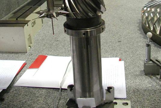
6 Measurement of Large Gears (CMM + Gear Software = CMM + Gear Tester) Gantry Type CMM for Gear Diameter up to 3700 mm Accuracy up to E = L / 400 [µm] P = 1.9 µm 6
 CMM for")

7 Measurement of small Gears (CMM + Gear Software = CMM + Gear Tester) CMM for Gear Diameter down to 2mm Accuracy up to E = L / 350 [µm] P = 0.8 µm 7
8 Quindos GEARHX - Evaluation Profile + Helix Profile (involute) Profile slope deviation f Hα Total profile deviation F α Profile form deviation f fα Profile crowning C α Tip relief (VDI/VDE 2607) Root relief (VDI/VDE 2607) K-chart evaluation Pressure angle modification Helix Helix slope evaluation f Hß Total helix deviation F ß Helix form deviation f fß Helix crowning C ß End relief (VDI/VDE 2607) K-chart Evaluation Helix angle modification 8
9 Quindos GEARHX - Evaluation Pitch + Runout Pitch & Runout Cumulative pitch deviation Fp Individual pitch deviation fp Adjacent pitch deviation fu Variance of pitch deviation Rp Radial runout Fr Dimension over 2 balls Dimension over 1 ball Span over n teeth Tooth thickness Evaluation with and without eccentricity 9

10 Quindos GEARHX certified by PTB (German National Institute) 10
11 Quindos GearXY Determination of unknown Gear 11 Strategy Define gear axis 1x probing at tip circle 1x probing at root circle 1x probing at upper and lower face 6 points at gear flank 5 at one flank 1 point at opposite flank Results Normal module Pressure angle Helix angle Addendum modification factor Crowning of profile and helix Tip circle diameter Root circle diameter Gear width
12 Quindos Gear Gauges Inspection of Involute and Lead Masters Involute Master Determination of fhα, Fα, ffα inside evaluation range Position and depth of flat areas (see plot) Determination of actual base circle diameter Evaluation with respect to actual or nominal base circle diameter Plot with respect to angle of roll or angle of roll Lead Master analog 12
 with Master Grid Profile Measurement like cylindrical gear Flank Trace Measurement like cylindrical gear Pitch & Runout Bestfit to improve alignment")
13 Quindos GEARSB Measurement of Straight Bevel Gears according to DIN 3971 Measurement of external & internal Gearings, Dies and Electrodes Topography Measurement with theoretical points (Octoid Gearing of the 1 st kind) with Master Grid Profile Measurement like cylindrical gear Flank Trace Measurement like cylindrical gear Pitch & Runout Bestfit to improve alignment 13
14 Quindos GEARSB - Evaluation of Straight Bevel Gear Topography Pitch Runout Tooth Thickness 14

15 Quindos GEARHX - Evaluation of Profile (involute) Flank trace evaluation according to Octoid geometry 15


16 Quindos GEARBV Spiral Bevel Gears and Crown Gears Spiral Bevel Gear Crown Gear 16


17 Quindos GEARBV Spiral Bevel Gear 17
18 Quindos GEARBV - Evaluation Import of Master Files e.g. in Gleason, Klingelnberg (KEGMES), DMG Format Export of average result file e.g. in Gleason Format Measurement of a Master Gear Automatic generation of the moving path without rotary table Actual nominal comparison of topography with different fitting methods Evaluation of pitch, runout and tooth thickness Quality Grade according DIN or AGMA Large size Pinions measured with axis mounted horizontally 18

19 Quindos GEARBV Interfaces to GLEASON, Klingelnberg, DMG I.E. Correction of Machine Settings G-Age 4/WIN GLEASON GAGE 4/WIN LEITZ PMM-C QUINDOS PHOENIX PMM-C 19


20 Quindos WORMHX, WORMGL, WWHEEL Cylindrical Worm, Double Env. Worm and Worm Wheel Cylindrical Worm Mounted horizontally Any length can be measured! Double Enveloping Worm Worm Wheel 20
21 Quindos WORMHX - Cylindrical Worm Cylindrical Worms of type ZA, ZI, ZN, ZK and ZC (DIN 3965) Single or multi start worms LH or RH lead Duplex Worms Mounted in vertical or horizontal position 21
 Lead at selectable diameter (Fpz, - per, fhß, ffß)")
 Runout (given or calculated ball diameter) Normal tooth thickness")
22 Quindos WORMHX - Cylindrical Worm evaluation Worm types ZA, ZI, ZN, ZK and ZC (DIN 3965) Lead at selectable diameter (Fpz, - per, fhß, ffß) Profile at selectable Z height (Fα, ffα, fhα, Cα) Axial pitch (Fp, fp, fu) Runout (given or calculated ball diameter) Normal tooth thickness Topography 22

23 Quindos WORMGL Double enveloping Worm (globoid) Several types of generation (inclined grinding disk or straight sided skiving wheel) 1 or multi-start worms LH or RH lead vertically or horizontally mounted Profile Lead Pitch Runout Axial bestfit independently for left and right flanks for improvement of machine setting 23

24 Quindos WWHEEL Worm Wheel Worm Wheels for Cylindrical Worms of the types ZA, ZI, ZN, ZK and ZC (DIN 3965). Calculation as conjugate gearing to the mating worm No Master Grid necessary Pitch Runout Dimension over 2 Balls Profile Helix Topography Bestfit of axial Position Evaluation accord. to DIN, BSI and AGMA 24
 pressure angle grinding disk parameter etc. 25")
25 Definition of Worm Wheel No. of teeth Tooth thickness Type (ZA,ZI,ZN,ZK,ZC) No. of starts Hand of lead (LH, RH) pressure angle grinding disk parameter etc. 25
26 Generation of Worm Wheel Flanks Worm point (x¹, y¹, z¹) Normal direction (i¹, j¹, k¹) Law of Gearing Worm Wheel point (x², y², z²) Normal direction (i², j², k²) 26

27 Quindos WWHEEL Profile Evaluation fhα Fα ffα Cα 27

28 Quindos WWHEEL Helix Evaluation fhß Fß ffß Cß 28

29 Quindos HOB Hob cutter Measurement of all features as defined in DIN Additionally to DIN the Axial Pitch and the Tooth Height for topping hobs All measurement also for multi start hobs The flutes can be straight or helical 29

30 Quindos HOB Hob Cutter Evaluation Radial and axial runout of test collars Radial runout of tooth tip Shape and position of cutting face Pitch of the flutes Deviation of flute lead over 100 mm Form deviation of cutting edge Tooth thickness Hob lead over cutting edge Base pitch deviations Axial pitch Tooth height 30

31 Hob Cutter for large gears (setup with cutting plates) Determination of typical deviation parameters of the Hob with a special Quindos program 31


32 Quindos BROACH Shell Broach shells with ring type spaces as well as helical chip spaces can be inspected. The gearing may be straight or helical with left hand or right hand lead. Tools for hard broaching with negative face angles can also be inspected 32
 dimension over 2 balls 33")
33 Quindos BROACH Evaluation lead deviation / axial runout of chip space pitch of chip space radial runout outer / inner stepping of profile location to keyway transverse pitch in finishing area diameter inner / outer (single positions) dimension over 2 balls 33
 transverse tooth profile form of tooth tip")
34 Quindos BROACH Evaluation radial stepping of inner / outer radius radial stepping of dimension over 1 ball face angle in normal plane back off angle (inner, outer, profile) transverse tooth profile form of tooth tip 34


35 Quindos SHAVER - Shaving Gear The option Shaving Gear provides the tools for the complete inspection of shaving cutters. The travel path of the CMM as well as all probing and scan lines required for the inspection are generated automatically. 35

36 Quindos SHAVER - Shaving Gears Evaluation Evaluation of Profile (involute) Profile slope deviation f Hα Total profile deviation F α Profile form deviation f fα Profile crowning C α Mean profile slope deviation f Hα Evaluation of Helix Helix slope deviation f Hß Tooth crowning C ß Mean helix slope deviation f Hßm Mean tooth crowning C ß 36

37 Quindos SHAVER - Shaving Gears Evaluation Evaluation of Runout and Pitch cumulative pitch deviation Fp individual pitch deviation fp adjacent pitch deviation fu variance of pitch deviation Rp radial runout Fr Dimension over balls Span over n teeth Tooth thickness Elimination of eccentricity 37
 dimension over")
38 Quindos SHAPER - Shaper Cutter Inspection of spur and helical shaper cutters according to DIN The cutting face can be conical or stepped. Following evaluations are considered axial runout of cutting face radial runout at OD tooth thickness rake angle, clearance angle helix angle pitch and runout (fp, Fp, fu, Rp, Fr) dimension over balls profile (f Hα, F α, f fα ) helix (f Hß, F ß, f fß ) 38


39 Quindos STEPGR Step Gears Cam Bodies of any size and shape Input: Transmission Law and a few basic parameters 39


40 Quindos STEPGR Step Gear Evaluation Surface Form Evaluation 40

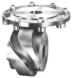
41 Quindos SCRCMP- Screw Compressor Complete measurement on a pallet QUINDOS: Pairing of Rotors 41

42 Quindos SCRCMP - Screw Compressor 42


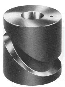
43 Quindos Camshaft- Camshafts & Complementary CAMS Complementary Cams Fully automatic inspection Of up to 24 Camshafts On 1 fixture! 43


44 Quindos Curvic Coupling Toothed gears used for accurate mating & centering of rotating parts. Application: Turbine rotors, Crankshafts 44 The Quindos Curvic Coupling option can be used to calibrate Curvic Coupling gauges used to check Curvic Coupling parts. The actual geometry is compared to the theoretical geometry in order to determine the pairing characteristics of the Curvic Coupling. Features: Axial runout of the tooth face Runout of the outside surface of the coupling. Pitch of the tooth flanks Topography of the tooth flanks Simulated pairing with a Curvic coupling master part Contact pattern measurement of paring Simulation with CC-Master


45 Quindos Curvic Coupling Evaluation Curvic coupling master model generated in QUINDOS using the curvic coupling data and Quindos CAD Topography measurement & results representatio n on the CAD model. 45

46 Quindos Curvic Coupling - Evaluation Topography measurement & contact representation Sweep scanning of the topography is used to determine the contact pattern of the CC to be checked. All of the flanks are measured in order to determine a true representation of the pairing quality of the curvic coupling with a master coupling. The result of the pairing is the eccentricity, axial runout & radial runout & pairing quality. 46


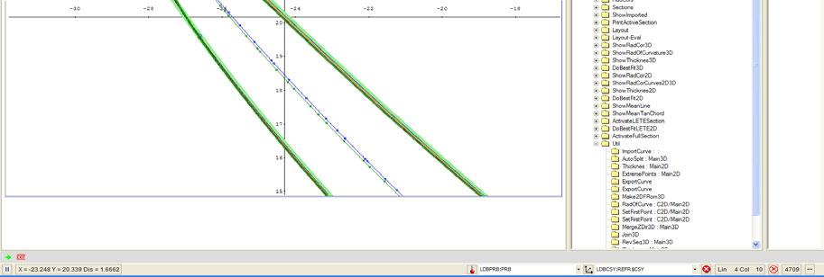
47 Ultimate Blade 2D Visualization and interactive evaluation tool for turbine profiles; Parameters can be defined interactive and saved for the CNC mode 47

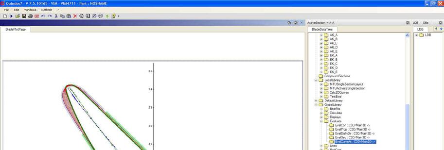
48 Ultimate Blade 48
49 Ultimate Blade Automatic edge radius recognition. 49
50 Ultimate Blade Automatic path correction 50

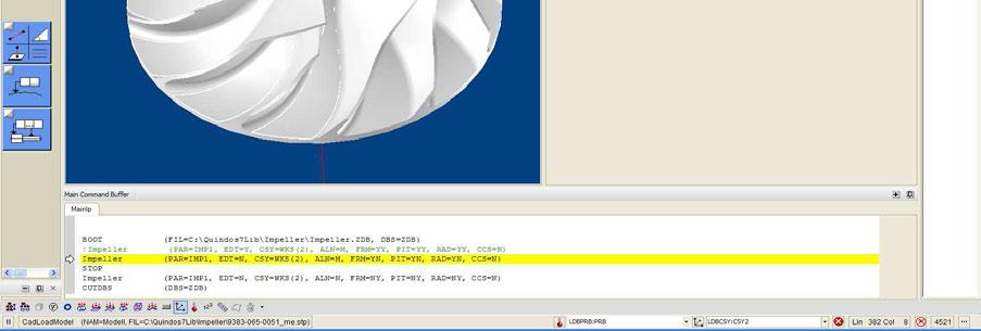

51 Impeller 51

52 Impeller 52
QUINDOS. the Analysis tool for Metrology
 QUINDOS the Analysis tool for Metrology QUINDOS PowerTrain Solutions the only upwards compatible metrology Software since 1985 (from VMS/ALPHA-VMS/SCO-UNIX/NT/WINDOWS 2000prof./ XPprof./ VISTA operating
KISSsoft 03/2013 Tutorial 15
 KISSsoft 03/2013 Tutorial 15 Bevel gears KISSsoft AG Rosengartenstrasse 4 8608 Bubikon Switzerland Tel: +41 55 254 20 50 Fax: +41 55 254 20 51 info@kisssoft.ag www.kisssoft.ag Contents 1 Starting KISSsoft...
KISSsoft 03/2017 Tutorial 15
 KISSsoft 03/2017 Tutorial 15 Bevel gears KISSsoft AG Rosengartenstrasse 4 8608 Bubikon Switzerland Tel: +41 55 254 20 50 Fax: +41 55 254 20 51 info@kisssoft.ag www.kisssoft.ag Contents 1 Starting KISSsoft...
DRAFT. KISSsoft Release 03/2013. Changes from Release 03/2012 to Release 03/2013. KISSsoft AG Rosengartenstrasse Bubikon Switzerland
 KISSsoft Release 03/2013 Changes from Release 03/2012 to Release 03/2013 DRAFT KISSsoft AG Rosengartenstrasse 4 8608 Bubikon Switzerland Tel: +41 55 254 20 50 Fax: +41 55 254 20 51 info@kisssoft.ag www.kisssoft.ag
Figure 1.1 "Bevel and hypoid gears" "Modules" Figure / August 2011 Release 03/2011
 KISSsoft Tutorial 015: Bevel Gears KISSsoft AG - +41 55 254 20 50 Uetzikon 4 - +41 55 254 20 51 8634 Hombrechtikon - info@kisssoft. AG Switzerland - www. KISSsoft. AG KISSsoft Tutorial: Bevel Gears 1 Starting
GMS 32. Double flank testing machine for gears
 GMS 32 Double flank testing machine gears Specifications max. diameter of measured gear 100 mm (4'') max. diameter of master gear 80 mm center distance 0... 90mm max. weight of gear 0.5 kg max. testing
1.6 Features of common gears
 1.6 Features of common gears Chapter 1.2 covered briefly on types of gear. The main gear features are explained here. Helical gear Helical gear has characteristics of transferability of larger load, less
Lecture (7) on. Gear Measurement. By Dr. Emad M. Saad. Industrial Engineering Dept. Faculty of Engineering. Fayoum University.
 on. Gear Measurement. By Dr. Emad M. Saad. Industrial Engineering Dept. Faculty of Engineering. Fayoum University.") 1 Lecture (7) on Gear Measurement Fayoum University By Dr. Emad M. Saad Industrial Engineering Dept. Faculty of Engineering Fayoum University Faculty of Engineering Industrial Engineering Dept. 2015-2016
1 Lecture (7) on Gear Measurement Fayoum University By Dr. Emad M. Saad Industrial Engineering Dept. Faculty of Engineering Fayoum University Faculty of Engineering Industrial Engineering Dept. 2015-2016
Gear Tooth Geometry - This is determined primarily by pitch, depth and pressure angle
 Gear Tooth Geometry - This is determined primarily by pitch, depth and pressure angle Addendum: The radial distance between the top land and the pitch circle. Addendum Circle: The circle defining the outer
Part VII: Gear Systems: Analysis
 Part VII: Gear Systems: Analysis This section will review standard gear systems and will provide the basic tools to perform analysis on these systems. The areas covered in this section are: 1) Gears 101:
Gear Measurement. Lecture (7) Mechanical Measurements
 Mechanical Measurements") 18 3. Gear profile checking 2. Involute measuring machine In this method the gear is held on a mandrel and circular disc of same diameter as the base circle of gear for the measurement is fixed on the
18 3. Gear profile checking 2. Involute measuring machine In this method the gear is held on a mandrel and circular disc of same diameter as the base circle of gear for the measurement is fixed on the
Involute Simulation Softwares Inc.
 Involute Simulation Softwares Inc. Updates / Recent changes Claude Gosselin, Ph.D., P.Eng. 2012-2017 www.hygears.com 1 Updates Contents HyGEARS update 29 November 2017 - Build 405.90-462... 3 HyGEARS and
GEAR GENERATION GEAR FORMING. Vipin K. Sharma
 GEAR GENERATION GEAR FORMING 1 GEAR MANUFACTURING Manufacturing of gears needs several processing operations in sequential stages depending upon the material and type of the gears and quality desired.
SECTION 8 BEVEL GEARING
 SECTION 8 BEVEL GEARING For intersecting shafts, bevel gears offer a good means of transmitting motion and power. Most transmissions occur at right angles, Figure 8-1, but the shaft angle can be any value.
11. GEAR TRANSMISSIONS
 11. GEAR TRANSMISSIONS 11.1. GENERAL CONSIDERATIONS Gears are one of the most important elements used in machinery. There are few mechanical devices that do not have the need to transmit power and motion
Set your Mobile Phones to Silent Respect your colleagues no private conversations Be on time
 Set your Mobile Phones to Silent Respect your colleagues no private conversations Be on time E. Francalanza 1 Thread Applications Thread Manufacturing Thread Design Thread Gaging Thread Measurement CMMs
DUDLEY'S" HANDBOOK OF PRACTICAL GEAR DESIGN AND MANUFACTURE. Stephen P. Radzevich
 Second Edition DUDLEY'S" HANDBOOK OF PRACTICAL GEAR DESIGN AND MANUFACTURE Stephen P. Radzevich LßP) CRC Press VV J Taylors Francis Group Boca Raton London New York CRC Press is an imprint of the Taylor
1.8 Rack shift of the gear
 1.8 Rack shift of the gear Undercut When Number of teeth is belo minimum as shon in Fig. 3, part of dedendum is no longer an Involute curve but ill look like a shape scooped out by cutter tool. Refer to
PRECISION GROUND GEARS Spur & Helical Gears
 Spur & Helical Gears Description Symbol Unit Equation Normal Module m n Transverse Module m t = m n / cos b Axial Module m x = m n / sin b Normal Pressure Angle a n degrees = 2 Transverse Pressure Angle
Tribology Aspects in Angular Transmission Systems
 Tribology Aspects in Angular Transmission Systems Part VI: Beveloid & Hypoloid Gears Dr. Hermann Stadtfeld (This article is part six of an eight-part series on the tribology aspects of angular gear drives.
Program Internal Gear Set Profile Shift Coefficients With Zero Backlash Introduction
 Program 60-107 Internal Gear Set Profile Shift Coefficients With Zero Backlash Introduction The purpose of this model is to provide data for a gear set when the tooth thickness and/or the center distance
Ernie Reiter and Irving Laskin
 F I N E P I T C H, P L A S T I C FA C E G E A R S : Design Ernie Reiter and Irving Laskin Ernie Reiter is a consultant specializing in the design of gears and geared products. He has authored modern software
Catalog Q Conversion For those wishing to ease themselves into working with metric gears
 1.3.4 Conversion For those wishing to ease themselves into working with metric gears by looking at them in terms of familiar inch gearing relationships and mathematics, Table 1-5 is offered as a means
SECTION 4 SPUR GEAR CALCULATIONS
 Function of α, or invα, is known as involute function. Involute function is very important in gear design. Involute function values can be obtained from appropriate tables. With the 3.1 Contact Ratio center
12/6/2013 9:09 PM. Chapter 13. Gears General. Dr. Mohammad Suliman Abuhaiba, PE
 Chapter 13 Gears General 1 2 Chapter Outline 1. Types of Gears 2. Nomenclature 3. Conjugate Action 4. Involute Properties 5. Fundamentals 6. Contact Ratio 7. Interference 8. The Forming of Gear Teeth 9.
ISO INTERNATIONAL STANDARD. Bevel and hypoid gear geometry. Géométrie des engrenages coniques et hypoïdes. First edition
 INTERNATIONAL STANDARD ISO 23509 First edition 2006-09-01 Bevel and hypoid gear geometry Géométrie des engrenages coniques et hypoïdes Reference number ISO 2006 Provläsningsexemplar / Preview PDF disclaimer
1/2/2015 2:04 PM. Chapter 13. Gears General. Dr. Mohammad Suliman Abuhaiba, PE
 Chapter 13 Gears General 1 2 Chapter Outline 1. Types of Gears 2. Nomenclature 3. Conjugate Action 4. Involute Properties 5. Fundamentals 6. Contact Ratio 7. Interference 8. The Forming of Gear Teeth 9.
Tribology Aspects in Angular Transmission Systems
 Tribology Aspects in Angular Transmission Systems Part II Straight Bevel Gears Dr. Hermann Stadtfeld (This is the second of an eight-part series on the tribology aspects of angular gear drives. Each article
The Geometry of Involute Gears
 The Geometry of Involute Gears J.R. Colbourne The Geometry of Involute Gears With 217 Illustrations Springer-Verlag New York Berlin Heidelberg London Paris Tokyo J.R. Colbourne Department of Mechanical
CH#13 Gears-General. Drive and Driven Gears 3/13/2018
 CH#13 Gears-General A toothed wheel that engages another toothed mechanism in order to change the speed or direction of transmitted motion The gear set transmits rotary motion and force. Gears are used
RAIL ENGINEERING SOLUTIONS. Traction Gearing Bogie Manufacture & Upgrade Wheels & Axles Components Inspection & Failure Analysis
 RAIL ENGINEERING SOLUTIONS Traction Gearing Bogie Manufacture & Upgrade Wheels & Axles Components Inspection & Failure Analysis Since 1969 Hofmann Engineering has provided specialist engineering services
1.7 Backlash. Summary of the backlash is play or clearance between one pair of gear. Fig. 17 Backlash
 1.7 Backlash Summary of the backlash is play or clearance between one pair of gear. Fig. 17 Backlash Great care is taken to produce the gear with zero deviation. However we are unable to completely eliminate
Verifying the accuracy of involute gear measuring machines R.C. Frazer and J. Hu Design Unit, Stephenson Building, University ofnewcastle upon Tyne,
 Verifying the accuracy of involute gear measuring machines R.C. Frazer and J. Hu Design Unit, Stephenson Building, University ofnewcastle upon Tyne, Abstract This paper describes the most common methods
Bibliography. [1] Buckingham, Earle: "Analytical Mechanics of Gears", McGraw-Hill, New York, 1949, and republished by Dover, New York, 1963.
![Bibliography. [1] Buckingham, Earle: Analytical Mechanics of Gears, McGraw-Hill, New York, 1949, and republished by Dover, New York, 1963.](/thumbs/87/96820687.jpg "Bibliography. [1] Buckingham, Earle: Analytical Mechanics of Gears, McGraw-Hill, New York, 1949, and republished by Dover, New York, 1963.") Bibliography The first five references listed are books on gearing. Some of them deal not only with the geometry, but also with many other aspects of gearing. However, the books are included in this bibliography
Bibliography The first five references listed are books on gearing. Some of them deal not only with the geometry, but also with many other aspects of gearing. However, the books are included in this bibliography
Technical Publications Catalog. October 2015
 Technical Publications Catalog October 2015 Table of Contents How to Purchase Documents... 1 Index of AGMA Standards and Information Sheets by Number... 1 Index of AGMA Standards and Information Sheets
 DEPARTMENT OF MECHANICAL ENGINEERING Subject code: ME6601 Subject Name: DESIGN OF TRANSMISSION SYSTEMS UNIT-I DESIGN OF TRANSMISSION SYSTEMS FOR FLEXIBLE ELEMENTS 1. What is the effect of centre distance
MODULE- 5 : INTRODUCTION TO HYDROSTATIC UNITS (PUMPS AND MOTORS)
") MODULE- 5 : INTRODUCTION TO HYDROSTATIC UNITS (PUMPS AND MOTORS) LECTURE- 18 : BASIC FEATURES OF SOME Hydraulic Pumps & Motors Introduction In this section we shall discuss the working principles and fundamental
MODULE- 5 : INTRODUCTION TO HYDROSTATIC UNITS (PUMPS AND MOTORS) LECTURE- 18 : BASIC FEATURES OF SOME Hydraulic Pumps & Motors Introduction In this section we shall discuss the working principles and fundamental
GEAR CONTENTS POWER TRANSMISSION GEAR TYPES OF GEARS NOMENCLATURE APPLICATIONS OF GEARS VELOCITY RATIO GEAR TRAINS EXAMPLE PROBLEMS AND QUESTIONS
 GEAR CONTENTS POWER TRANSMISSION GEAR TYPES OF GEARS NOMENCLATURE APPLICATIONS OF GEARS VELOCITY RATIO GEAR TRAINS EXAMPLE PROBLEMS AND QUESTIONS GEAR.. Power transmission is the movement of energy from
For more information please contact: Jim Woodhead, Works Manager
 KEYSPLINE ENGINEERING LTD GEAR & TRANSMISSION SPECILISTS STATION WORKS, MASBROUGH STREET, ROTHERHAM, S60 1HT Tel: 01709 559933 Fax: 01709 513011 Email: sales@keyspline.com Website: www.keyspline.com We
More Detail about Helical & Bevel Helical Reduction Gear Boxes.
 More Detail about Helical & Bevel Helical Reduction Gear Boxes. For Inspection & Checking of these Housings we have Brown & Sharpe (USA) CNC CMM with full automatic rotating Renishaw Probe Head with Inspection
Customer Application Examples
 Customer Application Examples The New, Powerful Gearwheel Module 1 SIMPACK Usermeeting 2006 Baden-Baden 21. 22. March 2006 The New, Powerful Gearwheel Module L. Mauer INTEC GmbH Wessling Customer Application
Design & Development of Precision Plastic Gear Transmissions
 Design & Development of Precision Plastic Gear Transmissions David Sheridan Senior Design Engineer TICONA 1 2012 Ticona Gears Webinar Gear_DesignPPT_AM_0212_016.pdf Overview Methodical and rational procedure
Metrology Prof. Dr Kanakuppi Sadashivappa Bapuji Institute of Engineering and Technology Davangere. Lecture 25 Introduction of Gears
 Metrology Prof. Dr Kanakuppi Sadashivappa Bapuji Institute of Engineering and Technology Davangere Lecture 25 Introduction of Gears I welcome you for the series of lecture on gear measurement and at module
Technical Publications Catalog. April 2014
 Technical Publications Catalog April 2014 Table of Contents American Gear Manufacturers Association... iii How to Purchase Documents... 1 Index of AGMA Standards and Information Sheets by Number... 1 Index
Chapter 8 Kinematics of Gears
 Chapter 8 Kinematics of Gears Gears! Gears are most often used in transmissions to convert an electric motor s high speed and low torque to a shaft s requirements for low speed high torque: Speed is easy
INVOLUTE SPIRAL FACE COUPLINGS AND GEARS: DESIGN APPROACH AND MANUFACTURING TECHNIQUE
 УДК 621.9.015 Dr. Alexander L. Kapelevich, Stephen D. Korosec 38 INVOLUTE SPIRAL FACE COUPLINGS AND GEARS: DESIGN APPROACH AND MANUFACTURING TECHNIQUE This paper presents spiral face gears with an involute
Metric Standards Worldwide Japanese Metric Standards In This Text
 ELEMENTS OF METRIC GEAR TECHNOLOGY Table of Contents Page SECTION 1 INTRODUCTION TO METRIC GEARS 329 1.1 Comparison Of Metric Gears With American Inch Gears 329 1.1.1 1.1.2 1.1.3 Comparison of Basic Racks
KINGS COLLEGE OF ENGINEERING DEPARTMENT OF MECHANICAL ENGINEERING
 KINGS COLLEGE OF ENGINEERING DEPARTMENT OF MECHANICAL ENGINEERING QUESTION BANK Sub Code/Name: ME 1352 DESIGN OF TRANSMISSION SYSTEMS Year/Sem: III / VI UNIT-I (Design of transmission systems for flexible
1 135 teeth to rack
 1. A spur gear with 46 teeth, 2.5 module has to be cut on a column and knee type horizontal milling machine with a rotary disc type form gear milling cutter. The 2.5 module cutter no. 3 is used on a blank
Introduction. Kinematics and Dynamics of Machines. Involute profile. 7. Gears
 Introduction The kinematic function of gears is to transfer rotational motion from one shaft to another Kinematics and Dynamics of Machines 7. Gears Since these shafts may be parallel, perpendicular, or
CHAPTER 5 PREVENTION OF TOOTH DAMAGE IN HELICAL GEAR BY PROFILE MODIFICATION
 90 CHAPTER 5 PREVENTION OF TOOTH DAMAGE IN HELICAL GEAR BY PROFILE MODIFICATION 5.1 INTRODUCTION In any gear drive the absolute and the relative transmission error variations normally increases with an
Gear Engineering Data. Spur Gear Gear Formulas Drive Selection Horsepower and Torque Tables
 Engineering Gear Engineering Data Spur Gear Gear Formulas Drive Selection Horsepower and Torque Tables G-79 Gear Selection Stock Spur Gear Drive Selection When designing a stock gear drive using the horsepower
Sheet 1 Variable loading
 Sheet 1 Variable loading 1. Estimate S e for the following materials: a. AISI 1020 CD steel. b. AISI 1080 HR steel. c. 2024 T3 aluminum. d. AISI 4340 steel heat-treated to a tensile strength of 1700 MPa.
Instantaneous Centre Method
 Instantaneous Centre Method The combined motion of rotation and translation of the link AB may be assumed to be a motion of pure rotation about some centre I, known as the instantaneous centre of rotation.
BEVELGEAR. Competence and Performance.
 BEVELGEAR Competence and Performance www.graessner.de General Advantages of Spiral, Hypoid and Zerol Bevel Gears High level of coverage due to the fact that several teeth are meshed simultaneously Resistant
MANUFACTURING OF GEAR BOXES
 Profile No.: 29 NIC Code: 29301 MANUFACTURING OF GEAR BOXES 1. INTRODUCTION: Gears play a prominent role in mechanical power transmission. A gear or cogwheel is a rotating machine part having cut teeth,
ANALITICAL METHOD TO CALCULATE THE UNKNOWN GEOMETRY OF CYLINDRICAL GEARS
 ANALITICAL METHOD TO CALCULATE THE UNKNOWN GEOMETRY OF CYLINDRICAL GEARS G. González Rey *, A. García Toll Universidad de Tecnológica de Aguascalientes, Blvd. Juan Pablo II, No. 30, Fracc. Exhacienda,
Technical Publications Catalog. October 2016
 Technical Publications Catalog October 2016 Table of Contents How to Purchase Documents... 1 Index of AGMA Standards and Information Sheets by Number... 1 Index of AGMA Standards and Information Sheets
T25 T25 T25 T27 T27 T28 T28 T28 T28 T29 T29 T29 T31 T37 T37 T38 T T T48
 1.0 INTRODUCTION 2.0 BASIC GEOMETRY OF SPUR GEARS 2.1 Basic Spur Gear Geometry 2.2 The Law of Gearing 2.3 The Involute Curve 2.4 Pitch Circles 2.5 Pitch 2.5.1 Circular Pitch 2.5.2 Diametral Pitch 2.5.3
AN OPTIMAL PROFILE AND LEAD MODIFICATION IN CYLINDRICAL GEAR TOOTH BY REDUCING THE LOAD DISTRIBUTION FACTOR
 AN OPTIMAL PROFILE AND LEAD MODIFICATION IN CYLINDRICAL GEAR TOOTH BY REDUCING THE LOAD DISTRIBUTION FACTOR Balasubramanian Narayanan Department of Production Engineering, Sathyabama University, Chennai,
Bevel and hypoid gear geometry
 Provläsningsexemplar / Preview INTERNATIONAL STANDARD ISO 23509 Second edition 2016-11-15 Bevel and hypoid gear geometry Géométrie des engrenages coniques et hypoïdes Reference number ISO 2016 Provläsningsexemplar
GEAR NOISE REDUCTION BY NEW APPROACHES IN GEAR FINISHING PROCESSES
 GEAR NOISE REDUCTION BY NEW APPROACHES IN GEAR FINISHING PROCESSES Nikam Akshay 1, Patil Shubham 2, Pathak Mayur 3, Pattewar Vitthal 4, Rawanpalle Mangesh 5 1,2,3,4,5 Department of Mechanical Engineering,
ME6601 DESIGN OF TRANSMISSION SYSTEMS
 SYED AMMAL ENGINEERING COLLEGE (Approved by the AICTE, New Delhi, Govt. of Tamilnadu and Affiliated to Anna University, Chennai) Established in 1998 - An ISO 9001:2008 Certified Institution Dr. E.M.Abdullah
LAPPING OR GRINDING? WHICH TECHNOLOGY IS THE RIGHT CHOICE IN THE AGE OF INDUSTRY 4.0?
 LAPPING OR GRINDING? WHICH TECHNOLOGY IS THE RIGHT CHOICE IN THE AGE OF INDUSTRY 4.0? Bevel gear transmissions for the automotive industry are subject to extremely stringent requirements. They must be
Thermal Analysis of Helical and Spiral Gear Train
 International Journal for Ignited Minds (IJIMIINDS) Thermal Analysis of Helical and Spiral Gear Train Dr. D V Ghewade a, S S Nagarale b & A N Pandav c a Principal, Department of Mechanical, GENESIS, Top-Kolhapur,
Model Library Power Transmission
 Model Library Power Transmission The Power Transmission libraries in SimulationX support the efficient modeling and analysis of mechanical powertrains as well as the simulation-based design of controlled
Measuring Threaded Holes
 Measuring Threaded Holes It s a common question In PC-DMIS I can use the pitch function within a circle feature so the probe would "follow" the thread. How are tapped holes measured in Calypso? I have
Engineering Information
 Engineering nformation Gear Nomenclature ADDENDUM (a) is the height by which a tooth projects beyond the pitch circle or pitch line. BASE DAMETER (D b ) is the diameter of the base cylinder from which
CHAPTER 3 page 35 PRINCIPLES OF GEAR-TOOTH GENERATION. .1 Angular Velocity Ratio
 CHAPTER 1 page 1..., ATURE, NOTATION AND CONVENTIONS TYPES OF GEAR 1.1 Spur 1.2 Helical 1.3 Double-Helical 1.4 Crossed Helical 1.5 Conical Involute 1.6 Bevel 1.7 Spiral Bevel 1.8 Hypoid 1.9 Worm NOMENCLATURE
What are the functions of gears? What is gear?
 8//0 hapter seven Laith atarseh are very important in power transmission between a drive rotor and driven rotor What are the functions of gears? - Transmit motion and torque (power) between shafts - Maintain
Internal Gears. No. of teeth (60) Module (1) Others (Ring Gear) Type (Internal Gear) Material (S45C)
 Module (1) Others (Ring Gear) Type (Internal Gear) Material (S45C)") ph: (410)8-10 (0)68-180 fx: (410)8-142 (0)872-929 rfq form: http://mdmetric.com/rfq.htm Internal Internal Miter CP Racks & Pinions Racks Helical Spur SI Steel Internal SIR Steel Ring m0. ~ Page 184 m2
ph: (410)8-10 (0)68-180 fx: (410)8-142 (0)872-929 rfq form: http://mdmetric.com/rfq.htm Internal Internal Miter CP Racks & Pinions Racks Helical Spur SI Steel Internal SIR Steel Ring m0. ~ Page 184 m2
Chapter seven. Gears. Laith Batarseh
 Chapter seven Gears Laith Batarseh Gears are very important in power transmission between a drive rotor and driven rotor What are the functions of gears? - Transmit motion and torque (power) between shafts
ISO Acceptance and re-verification tests for Coordinate Measuring Machines. a brief introduction
 ISO 10360 Acceptance and re-verification tests for Coordinate Measuring Machines a brief introduction ISO 10360 Acceptance and re-verification Tests for Coordinate Measuring Machines (CMMs) Consisting
Chapter 3. Transmission Components
 Chapter 3. Transmission Components The difference between machine design and structure design An important design problem in a mechanical system is how to transmit and convert power to achieve required
The Available Solution CYCLO DRIVE. Gearmotors & Speed Reducers. Series
 The Available Solution CYCLO DRIVE Gearmotors & Speed Reducers 6000 Series WHAT DO YOU THINK OF THIS? THESE ARE THE ADVANTAGES OF THE NEWEST CYCLO, 6000 SERIES: More frame sizes, gear ratios and motor
(POWER TRANSMISSION Methods)
") UNIT-5 (POWER TRANSMISSION Methods) It is a method by which you can transfer cyclic motion from one place to another or one pulley to another pulley. The ways by which we can transfer cyclic motion are:-
UNIT-5 (POWER TRANSMISSION Methods) It is a method by which you can transfer cyclic motion from one place to another or one pulley to another pulley. The ways by which we can transfer cyclic motion are:-
ANALYSIS OF SURFACE CONTACT STRESS FOR A SPUR GEAR OF MATERIAL STEEL 15NI2CR1MO28
 ANALYSIS OF SURFACE CONTACT STRESS FOR A SPUR GEAR OF MATERIAL STEEL 15NI2CR1MO28 D. S. Balaji, S. Prabhakaran and J. Harish Kumar Department of Mechanical Engineering, Chennai, India E-Mail: balajimailer@gmail.com
Positioning Committee. Marine Technology Society. DYNAMIC POSITIONING CONFERENCE September 18-19, 2001 THRUSTERS SESSION. Bevel Gears for Thrusters
 Author s Name Name of the Paper Session PDynamic Positioning Committee Marine Technology Society DYNAMIC POSITIONING CONFERENCE September 18-19, 2001 THRUSTERS SESSION Bevel Gears for Thrusters Peter Häger
Direction of Helix (R) No. of Teeth (20) Module (1) Others (Ground Gear) Type (Helical Gear) Material (SCM440)
 No. of Teeth (20) Module (1) Others (Ground Gear) Type (Helical Gear) Material (SCM440)") KH round Series Newly added m1 ~ 3 Page 168 SH Steel m2, 3 Page 178 CP acks acks Catalog Number of KHK Stock The Catalog Number for KHK stock gears is based on the simple formula listed below. Please order
KH round Series Newly added m1 ~ 3 Page 168 SH Steel m2, 3 Page 178 CP acks acks Catalog Number of KHK Stock The Catalog Number for KHK stock gears is based on the simple formula listed below. Please order
PHOTO ID Manufacturer Model Year CAT Category Description 1 Description Barber Colman 4-4HRS G0826 GEAR CUTTER SHARPENERS (Inclu...
 PHOTO ID Manufacturer Model Year CAT Category Description 1 Description 3840 Barber Colman 4-4HRS G0826 GEAR CUTTER SHARPENERS (Inclu... BARBER-COLMAN AUTOMATIC HYDRAULIC HOB SHARPENING MACHINE MODEL #4-4HRS
Highest Performance: Dyna Series
 Highest Performance: Dyna Series The Dyna Series is our highest performance right-angle gear reducer utilizing sophisticated hypoid gearing. The benefit of hypoid gearing is that it combines the space
Therefore, it is the general practice to test the tooth contact and backlash with a tester. Figure 19-5 shows the ideal contact for a worm gear mesh.
 19. Surface Contact Of Worm And Worm Gear There is no specific Japanese standard concerning worm gearing, except for some specifications regarding surface contact in JIS B 1741. Therefore, it is the general
CYLINDRICAL GEAR CONVERSIONS:
 CYLINDRICAL GEAR CONVERSIONS: AGMA TO ISO By G. González Rey, P. Frechilla Fernández, and R. José García Martín THE FOLLOWING IS AN IN-DEPTH EXAMINATION OF THE CONVERSION OF CYLINDRICAL GEARS IN THE AGMA
ANALYSIS OF GEAR QUALITY CRITERIA AND PERFORMANCE OF CURVED FACE WIDTH SPUR GEARS
 8 FASCICLE VIII, 8 (XIV), ISSN 11-459 Paper presented at Bucharest, Romania ANALYSIS OF GEAR QUALITY CRITERIA AND PERFORMANCE OF CURVED FACE WIDTH SPUR GEARS Laurentia ANDREI 1), Gabriel ANDREI 1) T, Douglas
Tooth thickness Dedendum. Addendum. Centre distance Nominal
 FORMULAS SPUR GEARS TO FIND:- PCD ØD MODULE No. of TEETH CP ADDENDUM DEDENDUM MODULE No. of TEETH x MOD (mm) (No. of TEETH + ) x MOD (mm) 5.4 MODULE CP π (mm) PCD MODULE (mm) MODULE x π (mm) MODULE (mm)
UNIT -I. Ans: They are specified by the no. of strands & the no. of wires in each strand.
 VETRI VINAYAHA COLLEGE OF ENGINEERING AND TECHNOLOGY, THOTTIAM, NAMAKKAL-621215. DEPARTMENT OF MECHANICAL ENGINEERING SIXTH SEMESTER / III YEAR ME6601 DESIGN OF TRANSMISSION SYSTEM (Regulation-2013) UNIT
How to Achieve a Successful Molded Gear Transmission
 How to Achieve a Successful Molded Gear Transmission Rod Kleiss Figure 1 A molding insert tool alongside the molded gear and the gear cavitiy. Molded plastic gears have very little in common with machined
Bevel Gears. Fig.(1) Bevel gears
 Bevel gears") Bevel Gears Bevel gears are cut on conical blanks to be used to transmit motion between intersecting shafts. The simplest bevel gear type is the straighttooth bevel gear or straight bevel gear as can be
Bevel Gears Bevel gears are cut on conical blanks to be used to transmit motion between intersecting shafts. The simplest bevel gear type is the straighttooth bevel gear or straight bevel gear as can be
Determination and improvement of bevel gear efficiency by means of loaded TCA
 Determination and improvement of bevel gear efficiency by means of loaded TCA Dr. J. Thomas, Dr. C. Wirth, ZG GmbH, Germany Abstract Bevel and hypoid gears are widely used in automotive and industrial
FORM ERROR CORRECTION OF BEVEL GEARS BY ELECTROCHEMICAL HONING PROCESS
 5 th International & 26 th All India Manufacturing Technology, Design and Research Conference (AIMTDR 2014) December 12 th 14 th, 2014, IIT Guwahati, Assam, India FORM ERROR CORRECTION OF BEVEL GEARS BY
Introduction to Gear Design
 Introduction to Gear Design Course No: M03-016 Credit: 3 PDH Robert P. Tata, P.E. Continuing Education and Development, Inc. 9 Greyridge Farm Court Stony Point, NY 10980 P: (877) 322-5800 F: (877) 322-4774
AGMA Catalog of Technical Publications
 Topic AGMA Catalog of Technical Publications 2000-2007 TABLE OF CONTENTS American Gear Manufacturers Association... ii How to Purchase ocuments... iii Index of AGMA Standards and Information Sheets by
ANALYSIS OF SPUR GEAR GEOMETRY AND STRENGTH WITH KISSSOFT SOFTWARE
 ANALYSIS OF SPUR GEAR GEOMETRY AND STRENGTH WITH KISSSOFT SOFTWARE Ashwini Gaikwad 1, Rajaram Shinde 2 1,2 Automobile Engineering Department, Rajarambapu Institute of Technology, Sakharale, Dist. Sangli,
STUDY FOR THE VERIFICATION OF THE TOOTH PROFILE ACCURACY OF THE AUTOMATIC GEAR DESIGN PROGRAM
 Transaction on Cams, gear, valves and pneumatic systems ISSN: 2229-8711 Online Publication, June 2011 www.pcoglobal.com/gjto.htm GP-M15 /GJTO STUDY FOR THE VERIFICATION OF THE TOOTH PROFILE ACCURACY OF
sof tware news Gleason OFFERS NEW SOFTWARE TO REDUCE NON-PRODUCTIVE GRINDING TIME
 sof tware news Gleason OFFERS NEW SOFTWARE TO REDUCE NON-PRODUCTIVE GRINDING TIME Gleason Corp. has developed three optional software modules designed to reduce overall machining time in its P 600/800
Spur gearing, Helical gearing [mm/iso] Pinion Gear ii Project information? i Calculation without errors.
![Spur gearing, Helical gearing [mm/iso] Pinion Gear ii Project information? i Calculation without errors.](/thumbs/80/81955134.jpg "Spur gearing, Helical gearing [mm/iso] Pinion Gear ii Project information? i Calculation without errors.") S Spur gearing, Helical gearing [mm/iso] i Calculation without errors. Pinion Gear ii Project information? Input section 1. Options of basic input parameters 1.1 Transferred power Pw [kw] 9.67 9.63 1.2
S Spur gearing, Helical gearing [mm/iso] i Calculation without errors. Pinion Gear ii Project information? Input section 1. Options of basic input parameters 1.1 Transferred power Pw [kw] 9.67 9.63 1.2
Performance requires quality.
 131 - With straight shank and square - Left-hand spiral 7-8 - First cut 1/4 of the cutting length (l 2 ) - Accuracy Hand Reamers DIN 26. Not suitable for blind holes. d 1 l 2 l 1 d 2 131 2, 25 5 1,6 21
GPK for Design and Rating of Industrial Gearboxes
 GPK for Design and Rating of Industrial Gearboxes KISSsys models: Bevel-Helical gear package includes KISSsys models for single bevel gearbox (right angle gearbox) and bevel gearboxes including one to
d -2,5 26,5 mm D -3,4 33 mm L mm; МК D mm L mm D mm L mm
 KAMAZ Publicly Traded Company Repair and Tooling Plant Tool making 2018 Twist drills Auger drills Drills with a thickened core Centre drills Twist step drills Solid carbide drills Inserted-blade drills
Main Catalogue. EichenbergerGewinde. 100 % Swiss made
 EichenbergerGewinde 100 % Swiss made Main Catalogue Carry ball screws Carry Speed-line high-helix ball screws Speedy high-helix lead screws Rondo round thread lead screws The choice is yours Thread rolling