CH#13 Gears-General. Drive and Driven Gears 3/13/2018
|
|
|
- Catherine Bernadette Scott
- 5 years ago
- Views:
Transcription


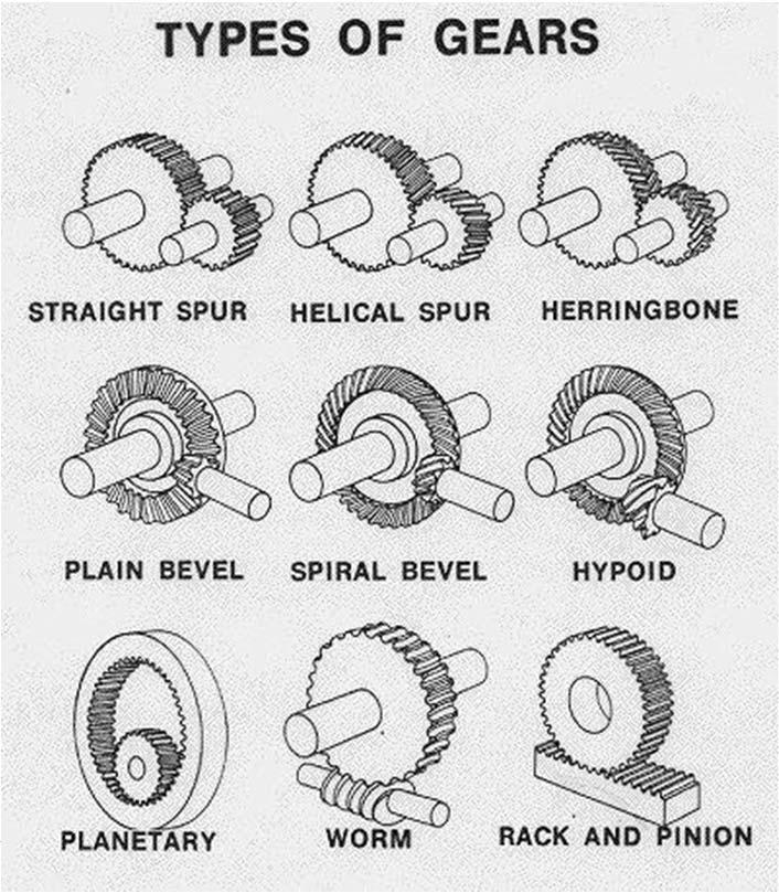
1 CH#13 Gears-General A toothed wheel that engages another toothed mechanism in order to change the speed or direction of transmitted motion The gear set transmits rotary motion and force. Gears are used in groups of two or more. A group of gears is called a gear train. The gears in a train are arranged so that their teeth closely interlock or mesh. The teeth on meshing gears are the same size so that they are of equal strength. Also, the spacing of the teeth is the same on each gear. Drive and Driven Gears Larger Gear can be called Wheel and Smaller Gear can be Called Pinion 1
2 Why Gears? The designer is frequently confronted with the problem of transferring power from one shaft to another while maintaining a definite ratio between the velocities of rotation of the shafts (to get the required torque). Transmission of specified angular motion from one shaft to another 2
3 3
4 4

5 Bevel Gear 5

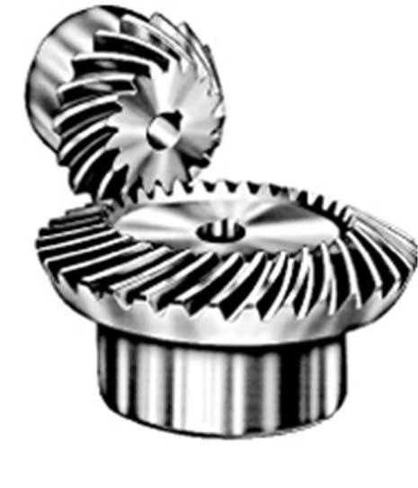
6 Spiral Bevel Gears 6

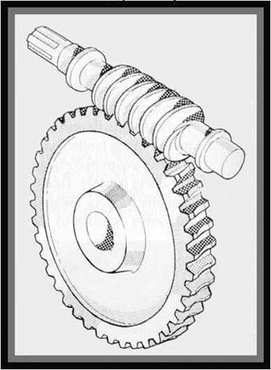
7 Worm Gear 7


8 Noncircular Gears The velocity ratio of non circular gears in not constant The purpose is to provide a time-varying output function in response to a constant velocity input 13-2 Nomenclature 8

9 13-2 Nomenclature Pitch Circle diameter (d) Circular pitch (p)= distance between two adjacent teeth = d/n = m (N is the number of teeth) Module (m)=d/n Diameteral pitch (P) = N/d Addendum = a = 1/P Dedendum = b = 1.25/P Tooth thickness = t = p/2 = d/2n = m/ Conjugate Action Involute Profile is one of the solutions to achieve Conjugate Action. 9

10 13-4 Involute Properties The forces at any instant are directed along the common normal ab to the two curves The line ab, representing the direction of action of the forces, is called the line of action The line of action will intersect the line of centres O-O at some point P The angular velocity ratio between the two arms is inversely proportional to their radii to the point P (Fundamental law of Gearing) Circles drawn through point P from each centres are called pitch circles, and the radius of each circle is called the pitch radius Point P is called the pitch point 13-5 Fundamentals Why gear? Suppose we wish to design a speed reducer such that the input speed is 1800 rev/min and output speed is 1200 rev/min. Fundamental law of gearing This is a ratio of 2:3; the gears pitch diameters would be in the same ratio, for example a 200mm pinion driving a 300mm gear (or 400mm pinion with 600mm gear and so on) Various dimensions found in gearing are always based on the pitch circles 10
11 13-5 Fundamentals Suppose we specify that an 18-tooth pinion is to mesh with a 30-tooth gear and that the diametral pitch of the gearset is to be 2 teeth per inch, Pressure angle represents the line of action (direction of force on the tooth) and is equal to 20 o, 25 o and rarely 14. Base circle r b is related to the pressure angle as; 13-5 Fundamentals Angle of approach Angle of recess 11
 Compute i. the circular pitch, ( ) ii. the centre distance, and ( ) iii. the radii of the base circles.")
12 Example (From old Ed.) A gearset of a 16-tooth driving a 40-tooth gear. The module is 5mm and the addendum and dedendum are 1 mand 1.25 m respectively (Full-depth system). The gears are cut using 20 o pressure angle a) Compute i. the circular pitch, ( ) ii. the centre distance, and ( ) iii. the radii of the base circles. ( ) b) In mounting, the centre distance of the shafts was incorrectly made 6mm larger. Compute the new values of pitch-circle radii, teeth and comment. How to draw (Graphical method) a c O1 P O2 d b 12
 Can be drawn using any CAD")
13 How to draw (Analytical method) Where c is the circumference of the circle How to draw (Analytical method) Can be drawn using any CAD system 13


14 Fundamentals of internal gears A rack can be imagined as a spur with an infinitely large pitch diameter The sides of the involute teeth on the rack are straight lines making an angle to the line of centres equal to the pressure angle Fundamentals of internal gears 14
15 Contact Ratio 13-6 Contact Ratio The animation shows clearly : 1. The contact point marching along the line of action 2. Guaranteed tooth tip clearance due to the addendum exceeding the base circle 3. A significant gap between the non-drive face of a pinion tooth and the adjacent wheel tooth 4. How load is transferred from one pair of contacting teeth to the next as rotation proceeds 13-6 Contact Ratio Initial contact occurs at a Addendum circle intersects the pressure line Final contact is at b Arc of approach = q a and Arc of recess = q r If q t =p, then only one tooth and its space will occupy the entire arc 15

16 13-6 Contact Ratio i.e. as soon as one tooth starts contact another ends. When q t = 1.2p means one tooth start contact at a before the other end contact. Two teeth are in contact for short period of time. This is define as and should not be less than 1.2 m c can be represented in terms of pitch circle radii as; 13-7 Interference and Undercutting If there are too few pinion teeth, then the gear cannot turn Also if the contact starts bellow the base circle where the profile is non-involute Interference is automatically removed by the generation process by introducing Undercutting 16
 and If m G = 4 and =20 o, then 15.")

17 13-7 Interference and Undercutting Undercutting should be avoided Two ways to avoid undercutting 1. Increase addendum on pinion and decrease on gear 2. Use minimum number of teeth such that; 1 2 * Where k = 1 for full depth, 0.8 for stub teeth (Refer to topic for different depths) and If m G = 4 and =20 o, then * Robert Lipp, Avoiding tooth interference in Gears, Machine Design, Vol. 54, No. 1, 1982, pp The Forming of Gear teeth Reading Assignment Gear teeth can be manufactured with large number of ways 1. Sand casting 2. Shell moulding 3. Investment casting 4. Centrifugal casting 5. Permanent-mould casting 6. Powder metallurgy process 7. Extrusion 8. Milling 9. Shaping 10. Hobbing 17

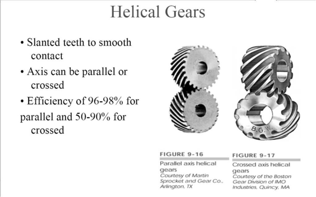
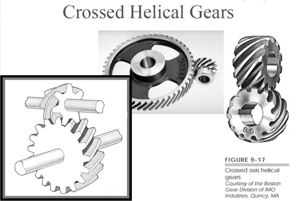
18 13-10 Parallel Helical Gears Parallel Helical Gears 18
19 13-10 Parallel Helical Gears a d Parallel Helical Gears 19

20 Interference in Helical Gear Example 13-2 A stock helical gear has a normal pressure angle of 20 o, a helix angle of 25 o, and a transverse module of 5.0mm, and has 18 teeth. Find (a) The pitch diameter ( ) (b) The transverse, normal and axial pitches,, (c) Normal module (d) The transverse pressure angle ) (Note: Solve Example 13-1) 20
21 13-12 Tooth Systems (Reading Assignment) Gear trains Consider a pinion 2 driving a gear 3. The speed of the driven gear is Where n = revolution or rev/min N = number of teeth d = pitch diameter Equation applies to any gearset no matter whether the gears are spur, helical, bevel, or worm The absolute-value signs are used to permit complete freedom in choosing positive and negative directions In the case of spur and parallel helical gears, the directions ordinarily corresponds to the right-hand rule and are positive for counter clockwise rotation 21

22 13-13 Gear trains The gear train shown is made up of five gears. The speed of gear 6 is Gear 3 is an idler, that its tooth numbers cancel in equation, and hence its effect is only changing the direction of rotation of gear 6 Gear 2, 3, and 5 are drivers, while 3, 4, and 6 are driven members Gear trains Train value e can thus be defined as; Pitch diameters can also be used in the above equation When the above equation is used for spur gears, positive e shows that the last gear rotates in the same sense as the first. Also it can be written that Where n L is the speed of the last gear in the train and n F is the speed of the first 22


23 13-13 Gear trains As a rough guideline, a train value of up to 10 to 1 can be obtained with one pair of gears. Greater ratios can be obtained in less space and with fewer dynamic problems by compounding additional pairs of gears. A two-stage compound gear train, such as shown in figure, can obtain a train value of up to 100 to Gear trains It is sometimes desirable for the input shaft and the output shaft of a two-stage compound gear train to be inline. This configuration is called a compound reverted gear train. Reference to figure, the distance constraint is 23

24 13-13 Gear trains Planetary or epicyclic gear train A gear train in which one gear axis rotates about other. Consist of Sun gear An arm and Planet gear 2 dof Example 13-4 A gearbox is needed to provide an exact 30:1 increase in speed, while minimizing the overall gearbox size. Specify appropriate teeth numbers. 24
25 Example 13-5 A gearbox is needed to provide an exact 30:1 increase in speed, while minimizing the overall gearbox size. The input and output shafts should be in-line. Specify appropriate teeth numbers Force Analysis Notation to be used Input gear will be designated as 2 and then gears will be numbered successively 3,4 etc. until the last gear in the train is arrived There may be several shafts involved, and usually one or two gears are mounted on each shaft as well as other elements; designates the shafts using lowercase letters of the alphabet, a, b, c, etc. Forces exerted by gear 2 on 3 will be F 23 Superscript notations will be used to indicate radial and tangential directions and coordinate directions 25
26 13-14 Force Analysis-Spur Gear Force Analysis-Spur Gear We define W t is the transmitted load The torque is (N-mm) Where T = T a2 and d=d 2 If is the pitch line velocity, then power is defined as; W t is in kn H is in kw d is in mm n is in rev/min 26


27 Example 13.6 Pinion 2 in figure runs at 1750 rpm and transmits 2.5kW to idler gear 3. The teeth are cut on 20 o fulldepth system and have module of m=2.5mm. Draw a free-body diagram of gear 3 and show all the forces that act upon it. Example
 2. Calculate 3. W t =F t 23 4.")


28 Solution Solution procedure 1. Calculate d 2 and d 3 ( and ) 2. Calculate 3. W t =F t F r 23 = F t 23 cos 5. Find F Gear 3 is idler so and 7. Calculate shaft reactions by F= Force Analysis-Helical Gear Horizontal plane= BCD Transverse plane= CDG Normal plane= ABC From which; Transverse Plane Normal Plane 90 o Horizontal plane 90 o = 28

29 13-16 Force Analysis-Helical Gear Direction of thrust force on shaft The direction in which the thrust loads acts on the shaft is determined by applying the right or left-hand rule to the driver For a left hand driver, if the fingers of left hand are pointed in the direction of rotation of driver, the thumb points in the direction of the thrust load acting on the shaft of driver Force Analysis-Helical Gear Forces on idler shaft Notice that the idler shaft reaction contains a couple (of thrust force w a ) tending to turn the shaft end-over-end. Also the idler teeth are bent both ways (due to tangential force w t ). Idler shafts are more severely loaded than other gears, belying their name. Thus, be cautious. 29

 4. Calculate tan 5. Calculate tan 6. Calculate tan 7. and 8. 0 (moment about A in the x-y plane, about z-axis) to get 9.")
30 Example 13.9 In Fig. a 750 W electric motor runs at 1800 rev/min in the clockwise direction, as viewed from the positive x axis. Keyed to the motor shaft is an 18-tooth helical pinion having a normal pressure angle of 20 o, a helix angle of 30 o, and a normal module of 3 mm. The hand of the helix is shown in the figure. Make a threedimensional sketch of the motor shaft and pinion, and show the forces acting on the pinion and the bearing reactions at A and B. The thrust should be taken out at A. Solution Steps 1. Calculate 2. Calculate 3. Calculate kn ( H in kw, d in mm, n in rpm) 4. Calculate tan 5. Calculate tan 6. Calculate tan 7. and 8. 0 (moment about A in the x-y plane, about z-axis) to get 9. 0to get (moment about A in the x-z plane, about y-axis) to get 11. 0to get 12. Torque on the shaft is 30
31 Sample problems 13-1 to13-4, 13-6, 13-8, 13-10, 13-15, 13-16, 13-20, 13-24, 13-31, 13-33, 13-34, 13-45, 13-47, From Shigley s Mechanical Engineering Design, 9 th Ed. (SI Units) 31
1/2/2015 2:04 PM. Chapter 13. Gears General. Dr. Mohammad Suliman Abuhaiba, PE
 Chapter 13 Gears General 1 2 Chapter Outline 1. Types of Gears 2. Nomenclature 3. Conjugate Action 4. Involute Properties 5. Fundamentals 6. Contact Ratio 7. Interference 8. The Forming of Gear Teeth 9.
12/6/2013 9:09 PM. Chapter 13. Gears General. Dr. Mohammad Suliman Abuhaiba, PE
 Chapter 13 Gears General 1 2 Chapter Outline 1. Types of Gears 2. Nomenclature 3. Conjugate Action 4. Involute Properties 5. Fundamentals 6. Contact Ratio 7. Interference 8. The Forming of Gear Teeth 9.
Introduction. Kinematics and Dynamics of Machines. Involute profile. 7. Gears
 Introduction The kinematic function of gears is to transfer rotational motion from one shaft to another Kinematics and Dynamics of Machines 7. Gears Since these shafts may be parallel, perpendicular, or
GEAR CONTENTS POWER TRANSMISSION GEAR TYPES OF GEARS NOMENCLATURE APPLICATIONS OF GEARS VELOCITY RATIO GEAR TRAINS EXAMPLE PROBLEMS AND QUESTIONS
 GEAR CONTENTS POWER TRANSMISSION GEAR TYPES OF GEARS NOMENCLATURE APPLICATIONS OF GEARS VELOCITY RATIO GEAR TRAINS EXAMPLE PROBLEMS AND QUESTIONS GEAR.. Power transmission is the movement of energy from
Part VII: Gear Systems: Analysis
 Part VII: Gear Systems: Analysis This section will review standard gear systems and will provide the basic tools to perform analysis on these systems. The areas covered in this section are: 1) Gears 101:
Gear Tooth Geometry - This is determined primarily by pitch, depth and pressure angle
 Gear Tooth Geometry - This is determined primarily by pitch, depth and pressure angle Addendum: The radial distance between the top land and the pitch circle. Addendum Circle: The circle defining the outer
(POWER TRANSMISSION Methods)
") UNIT-5 (POWER TRANSMISSION Methods) It is a method by which you can transfer cyclic motion from one place to another or one pulley to another pulley. The ways by which we can transfer cyclic motion are:-
UNIT-5 (POWER TRANSMISSION Methods) It is a method by which you can transfer cyclic motion from one place to another or one pulley to another pulley. The ways by which we can transfer cyclic motion are:-
Chapter 8 Kinematics of Gears
 Chapter 8 Kinematics of Gears Gears! Gears are most often used in transmissions to convert an electric motor s high speed and low torque to a shaft s requirements for low speed high torque: Speed is easy
What are the functions of gears? What is gear?
 8//0 hapter seven Laith atarseh are very important in power transmission between a drive rotor and driven rotor What are the functions of gears? - Transmit motion and torque (power) between shafts - Maintain
Chapter seven. Gears. Laith Batarseh
 Chapter seven Gears Laith Batarseh Gears are very important in power transmission between a drive rotor and driven rotor What are the functions of gears? - Transmit motion and torque (power) between shafts
ME6401 KINEMATICS OF MACHINERY UNIT- I (Basics of Mechanism)
") ME6401 KINEMATICS OF MACHINERY UNIT- I (Basics of Mechanism) 1) Define resistant body. 2) Define Link or Element 3) Differentiate Machine and Structure 4) Define Kinematic Pair. 5) Define Kinematic Chain.
ME6401 KINEMATICS OF MACHINERY UNIT- I (Basics of Mechanism) 1) Define resistant body. 2) Define Link or Element 3) Differentiate Machine and Structure 4) Define Kinematic Pair. 5) Define Kinematic Chain.
Sheet 1 Variable loading
 Sheet 1 Variable loading 1. Estimate S e for the following materials: a. AISI 1020 CD steel. b. AISI 1080 HR steel. c. 2024 T3 aluminum. d. AISI 4340 steel heat-treated to a tensile strength of 1700 MPa.
11/23/2013. Chapter 13. Gear Trains. Dr. Mohammad Suliman Abuhiba, PE
 Chapter 13 Gear Trains 1 2 13.2. Types of Gear Trains 1. Simple gear train 2. Compound gear train 3. Reverted gear train 4. Epicyclic gear train: axes of shafts on which the gears are mounted may move
2. a) What is pantograph? What are its uses? b) Prove that the peaucellier mechanism generates a straight-line motion. (5M+10M)
 What is pantograph? What are its uses? b) Prove that the peaucellier mechanism generates a straight-line motion. (5M+10M)") Code No: R22032 R10 SET - 1 1. a) Define the following terms? i) Link ii) Kinematic pair iii) Degrees of freedom b) What are the inversions of double slider crank chain? Describe any two with neat sketches.
Code No: R22032 R10 SET - 1 1. a) Define the following terms? i) Link ii) Kinematic pair iii) Degrees of freedom b) What are the inversions of double slider crank chain? Describe any two with neat sketches.
Instantaneous Centre Method
 Instantaneous Centre Method The combined motion of rotation and translation of the link AB may be assumed to be a motion of pure rotation about some centre I, known as the instantaneous centre of rotation.
Catalog Q Conversion For those wishing to ease themselves into working with metric gears
 1.3.4 Conversion For those wishing to ease themselves into working with metric gears by looking at them in terms of familiar inch gearing relationships and mathematics, Table 1-5 is offered as a means
Basic Fundamentals of Gear Drives
 Basic Fundamentals of Gear Drives Course No: M06-031 Credit: 6 PDH A. Bhatia Continuing Education and Development, Inc. 9 Greyridge Farm Court Stony Point, NY 10980 P: (877) 322-5800 F: (877) 322-4774
KINGS COLLEGE OF ENGINEERING DEPARTMENT OF MECHANICAL ENGINEERING
 KINGS COLLEGE OF ENGINEERING DEPARTMENT OF MECHANICAL ENGINEERING QUESTION BANK Sub Code/Name: ME 1352 DESIGN OF TRANSMISSION SYSTEMS Year/Sem: III / VI UNIT-I (Design of transmission systems for flexible
 DEPARTMENT OF MECHANICAL ENGINEERING Subject code: ME6601 Subject Name: DESIGN OF TRANSMISSION SYSTEMS UNIT-I DESIGN OF TRANSMISSION SYSTEMS FOR FLEXIBLE ELEMENTS 1. What is the effect of centre distance
Chapter 3. Transmission Components
 Chapter 3. Transmission Components The difference between machine design and structure design An important design problem in a mechanical system is how to transmit and convert power to achieve required
KINEMATICS OF MACHINARY UBMC302 QUESTION BANK UNIT-I BASICS OF MECHANISMS PART-A
 KINEMATICS OF MACHINARY UBMC302 QUESTION BANK UNIT-I BASICS OF MECHANISMS PART-A 1. Define the term Kinematic link. 2. Classify kinematic links. 3. What is Mechanism? 4. Define the terms Kinematic pair.
St.MARTIN S ENGINEERING COLLEGE Dhulapally, Secunderabad
 St.MARTIN S ENGINEERING COLLEGE Dhulapally, Secunderabad-500 014 Subject: Kinematics of Machines Class : MECH-II Group A (Short Answer Questions) UNIT-I 1 Define link, kinematic pair. 2 Define mechanism
Program Internal Gear Set Profile Shift Coefficients With Zero Backlash Introduction
 Program 60-107 Internal Gear Set Profile Shift Coefficients With Zero Backlash Introduction The purpose of this model is to provide data for a gear set when the tooth thickness and/or the center distance
Bevel Gears. Fig.(1) Bevel gears
 Bevel gears") Bevel Gears Bevel gears are cut on conical blanks to be used to transmit motion between intersecting shafts. The simplest bevel gear type is the straighttooth bevel gear or straight bevel gear as can be
Bevel Gears Bevel gears are cut on conical blanks to be used to transmit motion between intersecting shafts. The simplest bevel gear type is the straighttooth bevel gear or straight bevel gear as can be
Lecture (7) on. Gear Measurement. By Dr. Emad M. Saad. Industrial Engineering Dept. Faculty of Engineering. Fayoum University.
 on. Gear Measurement. By Dr. Emad M. Saad. Industrial Engineering Dept. Faculty of Engineering. Fayoum University.") 1 Lecture (7) on Gear Measurement Fayoum University By Dr. Emad M. Saad Industrial Engineering Dept. Faculty of Engineering Fayoum University Faculty of Engineering Industrial Engineering Dept. 2015-2016
1 Lecture (7) on Gear Measurement Fayoum University By Dr. Emad M. Saad Industrial Engineering Dept. Faculty of Engineering Fayoum University Faculty of Engineering Industrial Engineering Dept. 2015-2016
Bibliography. [1] Buckingham, Earle: "Analytical Mechanics of Gears", McGraw-Hill, New York, 1949, and republished by Dover, New York, 1963.
![Bibliography. [1] Buckingham, Earle: Analytical Mechanics of Gears, McGraw-Hill, New York, 1949, and republished by Dover, New York, 1963.](/thumbs/87/96820687.jpg "Bibliography. [1] Buckingham, Earle: Analytical Mechanics of Gears, McGraw-Hill, New York, 1949, and republished by Dover, New York, 1963.") Bibliography The first five references listed are books on gearing. Some of them deal not only with the geometry, but also with many other aspects of gearing. However, the books are included in this bibliography
Bibliography The first five references listed are books on gearing. Some of them deal not only with the geometry, but also with many other aspects of gearing. However, the books are included in this bibliography
1.6 Features of common gears
 1.6 Features of common gears Chapter 1.2 covered briefly on types of gear. The main gear features are explained here. Helical gear Helical gear has characteristics of transferability of larger load, less
CHAPTER 5 PREVENTION OF TOOTH DAMAGE IN HELICAL GEAR BY PROFILE MODIFICATION
 90 CHAPTER 5 PREVENTION OF TOOTH DAMAGE IN HELICAL GEAR BY PROFILE MODIFICATION 5.1 INTRODUCTION In any gear drive the absolute and the relative transmission error variations normally increases with an
Unit IV GEARS. Gallery
 Gallery Components of a typical, four stroke cycle, DOHC piston engine. (E) Exhaust camshaft, (I) Intake camshaft, (S) Spark plug, (V) Valves, (P) Piston, (R) Connecting rod, (C) Crankshaft, (W) Water
UNIT -I. Ans: They are specified by the no. of strands & the no. of wires in each strand.
 VETRI VINAYAHA COLLEGE OF ENGINEERING AND TECHNOLOGY, THOTTIAM, NAMAKKAL-621215. DEPARTMENT OF MECHANICAL ENGINEERING SIXTH SEMESTER / III YEAR ME6601 DESIGN OF TRANSMISSION SYSTEM (Regulation-2013) UNIT
The Geometry of Involute Gears
 The Geometry of Involute Gears J.R. Colbourne The Geometry of Involute Gears With 217 Illustrations Springer-Verlag New York Berlin Heidelberg London Paris Tokyo J.R. Colbourne Department of Mechanical
CHENDU COLLEGE OF ENGINEERING & TECHNOLOGY DEPARTMENT OF MECHANICAL ENGINEERING QUESTION BANK IV SEMESTER
 CHENDU COLLEGE OF ENGINEERING & TECHNOLOGY DEPARTMENT OF MECHANICAL ENGINEERING QUESTION BANK IV SEMESTER Sub Code: ME 6401 KINEMATICS OF MACHINERY UNIT-I PART-A 1. Sketch and define Transmission angle
1. (a) Discuss various types of Kinematic links with examples. (b) Explain different types of constrained motions with examples.
 Discuss various types of Kinematic links with examples. (b) Explain different types of constrained motions with examples.") Code No: RR310304 Set No. 1 III B.Tech I Semester Supplementary Examinations, February 2007 KINEMATICS OF MACHINERY ( Common to Mechanical Engineering, Mechatronics and Production Engineering) Time: 3
Code No: RR310304 Set No. 1 III B.Tech I Semester Supplementary Examinations, February 2007 KINEMATICS OF MACHINERY ( Common to Mechanical Engineering, Mechatronics and Production Engineering) Time: 3
Mechanism Feasibility Design Task
 Mechanism Feasibility Design Task Dr. James Gopsill 1 Contents 1. Last Week 2. Types of Gear 3. Gear Definitions 4. Gear Forces 5. Multi-Stage Gearbox Example 6. Gearbox Design Report Section 7. This Weeks
ME6601 DESIGN OF TRANSMISSION SYSTEMS
 SYED AMMAL ENGINEERING COLLEGE (Approved by the AICTE, New Delhi, Govt. of Tamilnadu and Affiliated to Anna University, Chennai) Established in 1998 - An ISO 9001:2008 Certified Institution Dr. E.M.Abdullah
Effect of Geometry Factor I & J Factor Multipliers in the performance of Helical Gears
 Effect of Geometry Factor I & J Factor Multipliers in the performance of Helical Gears 1 Amit D. Modi, 2 Manan B. Raval, 1 Lecturer, 2 Lecturer, 1 Department of Mechanical Engineering, 2 Department of
Engineering Information
 Engineering nformation Gear Nomenclature ADDENDUM (a) is the height by which a tooth projects beyond the pitch circle or pitch line. BASE DAMETER (D b ) is the diameter of the base cylinder from which
11. GEAR TRANSMISSIONS
 11. GEAR TRANSMISSIONS 11.1. GENERAL CONSIDERATIONS Gears are one of the most important elements used in machinery. There are few mechanical devices that do not have the need to transmit power and motion
DUDLEY'S" HANDBOOK OF PRACTICAL GEAR DESIGN AND MANUFACTURE. Stephen P. Radzevich
 Second Edition DUDLEY'S" HANDBOOK OF PRACTICAL GEAR DESIGN AND MANUFACTURE Stephen P. Radzevich LßP) CRC Press VV J Taylors Francis Group Boca Raton London New York CRC Press is an imprint of the Taylor
SECTION 8 BEVEL GEARING
 SECTION 8 BEVEL GEARING For intersecting shafts, bevel gears offer a good means of transmitting motion and power. Most transmissions occur at right angles, Figure 8-1, but the shaft angle can be any value.
 DEPARTMENT OF MECHANICAL ENGINEERING ME6401- KINEMATICS OF MACHINERY QUESTION BANK Part-A Unit 1-BASICS OF MECHANISMS 1. Define degrees of freedom. 2. What is meant by spatial mechanism? 3. Classify the
Introduction to Gear Design
 Introduction to Gear Design Course No: M03-016 Credit: 3 PDH Robert P. Tata, P.E. Continuing Education and Development, Inc. 9 Greyridge Farm Court Stony Point, NY 10980 P: (877) 322-5800 F: (877) 322-4774
Metrology Prof. Dr Kanakuppi Sadashivappa Bapuji Institute of Engineering and Technology Davangere. Lecture 25 Introduction of Gears
 Metrology Prof. Dr Kanakuppi Sadashivappa Bapuji Institute of Engineering and Technology Davangere Lecture 25 Introduction of Gears I welcome you for the series of lecture on gear measurement and at module
Session #3 Gears: Force Transmission & Gear Trains. Dan Frey
 Session #3 Gears: Force Transmission & Gear Trains Dan Frey Today s Agenda Pass out second reading packet Pass out loaner laptops Introduce project teams Gears Force Transmission Gear Trains Survey HW
Graphical representation of a gear
 Homework 4 Gears Gears are designed to transmit rotary motion. Often they are arranged in a gear train (meshed together). Gear trains provide a change in speed, torque (turning force) and direction (clockwise
1.8 Rack shift of the gear
 1.8 Rack shift of the gear Undercut When Number of teeth is belo minimum as shon in Fig. 3, part of dedendum is no longer an Involute curve but ill look like a shape scooped out by cutter tool. Refer to
GEARING. Theory of. Stephen. Kinetics, Geometry, and Synthesis. P. Radzevich. /Ov CRC Press yc*** J Taylor& Francis Croup Boca Raton
 Theory of GEARING Kinetics, Geometry, and Synthesis Stephen P. Radzevich /Ov CRC Press yc*** J Taylor& Francis Croup Boca Raton London New York CRC Press is an imprint of the Taylor & Francis Group, an
428 l Theory of Machines
 428 l heory of Machines 13 Fea eatur tures es 1. Introduction. 2. ypes of Gear rains. 3. Simple Gear rain. 4. ompound Gear rain. 5. Design of Spur Gears. 6. Reverted Gear rain. 7. picyclic Gear rain. 8.
Theory of Machines. CH-1: Fundamentals and type of Mechanisms
 CH-1: Fundamentals and type of Mechanisms 1. Define kinematic link and kinematic chain. 2. Enlist the types of constrained motion. Draw a label sketch of any one. 3. Define (1) Mechanism (2) Inversion
'' ''' '' ''' Code No: R R16 SET - 1
 Code No: R161232 R16 SET - 1 1. a) List the Primary requirements of a Steam Boiler. (2M) b) What are the distinguishing features between a Casting and a Pattern? (2M) c) Define (i) Brake Power; (ii) Indicated
Code No: R Set No. 1
 Code No: R05310304 Set No. 1 III B.Tech I Semester Regular Examinations, November 2007 KINEMATICS OF MACHINERY ( Common to Mechanical Engineering, Mechatronics, Production Engineering and Automobile Engineering)
A Study on Noncircular Gears with Non-Uniform Teeth
 A Study on Noncircular Gears with Non-Uniform Teeth Kazushi Kumagai* 1 and Tetsuya Oizumi* *1 Department of Infomation System, Sendai National College of Technology 4-16-1 Ayashi-Chuo, Aoba-ku, Sendai
1 135 teeth to rack
 1. A spur gear with 46 teeth, 2.5 module has to be cut on a column and knee type horizontal milling machine with a rotary disc type form gear milling cutter. The 2.5 module cutter no. 3 is used on a blank
Bevel Gears n A Textbook of Machine Design
 080 n A Textbook of Machine Design C H A P T E R 30 Bevel Gears. Introduction.. Classification of Bevel Gears. 3. Terms used in Bevel Gears. 4. Determination of Pitch Angle for Bevel Gears. 5. Proportions
INVOLUTE SPIRAL FACE COUPLINGS AND GEARS: DESIGN APPROACH AND MANUFACTURING TECHNIQUE
 УДК 621.9.015 Dr. Alexander L. Kapelevich, Stephen D. Korosec 38 INVOLUTE SPIRAL FACE COUPLINGS AND GEARS: DESIGN APPROACH AND MANUFACTURING TECHNIQUE This paper presents spiral face gears with an involute
 VALLIAMMAI ENGINEERING COLLEGE DEPARTMENT OF MECHANICAL ENGINEERING ME6401- KINEMATICS OF MACHINERY QUESTION BANK PART-A Unit 1-BASICS OF MECHANISMS 1. Define degrees of freedom. BT1 2. Describe spatial
FIRSTRANKER. 2. (a) Distinguish (by neat sketches) betweenpeaucellier mechanism and Hart mechanism.
 Distinguish (by neat sketches) betweenpeaucellier mechanism and Hart mechanism.") Code No: 07A51404 R07 Set No. 2 IIIB.Tech I Semester Examinations,May 2011 KINEMATICS OF MACHINERY Mechatronics Time: 3 hours Max Marks: 80 Answer any FIVE Questions All Questions carry equal marks 1.
Code No: 07A51404 R07 Set No. 2 IIIB.Tech I Semester Examinations,May 2011 KINEMATICS OF MACHINERY Mechatronics Time: 3 hours Max Marks: 80 Answer any FIVE Questions All Questions carry equal marks 1.
CHENDU COLLEGE OF ENGINEERING & TECHNOLOGY DEPARTMENT OF MECHANICAL ENGINEERING QUESTION BANK
 CHENDU COLLEGE OF ENGINEERING & TECHNOLOGY DEPARTMENT OF MECHANICAL ENGINEERING QUESTION BANK Sub Code: ME 2342 DESIGN OF TRANSMISSION SYSTEM UNIT - I 1. How the bevel gears are classified? Explain with
Lecture 13 BEVEL GEARS
 Lecture 13 BEVEL GEARS CONTENTS 1. Bevel gear geometry and terminology 2. Bevel gear force analysis 3. Bending stress analysis 4. Contact stress analysis 5. Permissible bending fatigue stress 6. Permissible
Different types of gears. Spur gears. Idler gears. Worm gears. Bevel gears. Belts & Pulleys
 GEARS Robot Gears By using different gear diameters, you can exchange between rotational (or translation) velocity and torque. by looking at the motor datasheet you can determine the output velocity and
SYED AMMAL ENGINEERING COLLEGE
 SYED AMMAL ENGINEERING COLLEGE (Approved by the AICTE, New Delhi, Govt. of Tamilnadu and Affiliated to Anna University, Chennai) Established in 1998 - An ISO 9001:2000 Certified Institution Dr. E.M.Abdullah
GEAR GENERATION GEAR FORMING. Vipin K. Sharma
 GEAR GENERATION GEAR FORMING 1 GEAR MANUFACTURING Manufacturing of gears needs several processing operations in sequential stages depending upon the material and type of the gears and quality desired.
T25 T25 T25 T27 T27 T28 T28 T28 T28 T29 T29 T29 T31 T37 T37 T38 T T T48
 1.0 INTRODUCTION 2.0 BASIC GEOMETRY OF SPUR GEARS 2.1 Basic Spur Gear Geometry 2.2 The Law of Gearing 2.3 The Involute Curve 2.4 Pitch Circles 2.5 Pitch 2.5.1 Circular Pitch 2.5.2 Diametral Pitch 2.5.3
Copyright Notice. Small Motor, Gearmotor and Control Handbook Copyright Bodine Electric Company. All rights reserved.
 Copyright Notice Small Motor, Gearmotor and Control Handbook Copyright 1993-2003 Bodine Electric Company. All rights reserved. Unauthorized duplication, distribution, or modification of this publication,
SECTION 4 SPUR GEAR CALCULATIONS
 Function of α, or invα, is known as involute function. Involute function is very important in gear design. Involute function values can be obtained from appropriate tables. With the 3.1 Contact Ratio center
1.7 Backlash. Summary of the backlash is play or clearance between one pair of gear. Fig. 17 Backlash
 1.7 Backlash Summary of the backlash is play or clearance between one pair of gear. Fig. 17 Backlash Great care is taken to produce the gear with zero deviation. However we are unable to completely eliminate
Chapter 1 Gear Design
 Chapter 1 Gear Design GTU Paper Analysis Sr. No. Questions Nov 16 May 17 Nov 17 May 18 Theory 1. Explain the following terms used in helical gears: (a) Helix angle; (b) Normal pitch; (c) Axial pitch; (d)
Title Objective Scope LITERATURE REVIEW
 Title Objective Scope : Car Gear System : Investigate the force conversion in the gear system : Low rev engine match with five speed manual transmission Low rev engine match with four speed-auto transmission
Design and Analysis of Six Speed Gear Box
 Design and Analysis of Six Speed Gear Box Ujjayan Majumdar 1, Sujit Maity 2, Gora Chand Chell 3 1,2 Student, Department of Mechanical Engineering, Jalpaiguri Government Engineering College, Jalpaiguri,
Design of Helical Gear and Analysis on Gear Tooth
 Design of Helical Gear and Analysis on Gear Tooth Indrale Ratnadeep Ramesh Rao M.Tech Student ABSTRACT Gears are mainly used to transmit the power in mechanical power transmission systems. These gears
we will learn how to conduct force and torque analysis on gears in order to calculate bearing
 8.1 Introduction to Gears Gears are used to transmit motion and torque from one shaft to another. In this section we will discuss the kinematics of gears; that is, the motion relationships between gears.
Simple Gears and Transmission
 Simple Gears and Transmission Simple Gears and Transmission page: of 4 How can transmissions be designed so that they provide the force, speed and direction required and how efficient will the design be?
Gear Engineering Data. Spur Gear Gear Formulas Drive Selection Horsepower and Torque Tables
 Engineering Gear Engineering Data Spur Gear Gear Formulas Drive Selection Horsepower and Torque Tables G-79 Gear Selection Stock Spur Gear Drive Selection When designing a stock gear drive using the horsepower
FRICTION DEVICES: DYNAMOMETER. Presented by: RONAK D. SONI Assistant Professor Parul Institute of Technology, Parul University
 FRICTION DEVICES: DYNAMOMETER Presented by: RONAK D. SONI Assistant Professor Parul Institute of Technology, Parul University DYNAMOMETER A dynamometer is a brake but in addition it has a device to measure
Fig. 1 Two stage helical gearbox
 Lecture 17 DESIGN OF GEARBOX Contents 1. Commercial gearboxes 2. Gearbox design. COMMERICAL GEARBOX DESIGN Fig. 1 Two stage helical gearbox Fig. 2. A single stage bevel gearbox Fig. 4 Worm gearbox HELICAL
Subject with Code: Kinematic of Machinery (16ME304)Course & Branch: B. Tech - ME Year &Sem : II-B. Tech &I-Sem Regulation: R16
Course & Branch: B. Tech - ME Year &Sem : II-B. Tech &I-Sem Regulation: R16") SIDDHARTH INSTITUTE OF ENGINEERING &TECHNOLOGY:: PUTTUR (Approved by AICTE, New Delhi & Affiliated to JNTUA, Anantapuramu) (Accredited by NBA & Accredited by NAAC with A Grade) (An ISO 9001:2008 Certified
SIDDHARTH INSTITUTE OF ENGINEERING &TECHNOLOGY:: PUTTUR (Approved by AICTE, New Delhi & Affiliated to JNTUA, Anantapuramu) (Accredited by NBA & Accredited by NAAC with A Grade) (An ISO 9001:2008 Certified
INSTITUTE OF AERONAUTICAL ENGINEERING
 INSTITUTE OF AERONAUTICAL ENGINEERING (Autonomous) Dundigal, Hyderabad -500 043 Course Name Course Code Class Branch MECHANICAL ENGINEERING TUTORIAL QUESTION BANK 2015 2016 : KINEMATICS OF MACHINES : A40309
BHARATHIDASAN ENGINEERING COLLEGE DEPARTMENT OF MECHANICAL ENGINEERING ME6401- KINEMATICS OF MACHINERY QUESTION BANK
 1 BHARATHIDASAN ENGINEERING COLLEGE DEPARTMENT OF MECHANICAL ENGINEERING ME6401- KINEMATICS OF MACHINERY QUESTION BANK Unit 1-BASICS OF MECHANISMS PART-A 1) Differentiate between a machine and a structure?
Chain Drives. Pitch. Basic Types -There are six major types of power-
 1 2 Power transmission chains have two things in common; side bars or link plates, and pin and bushing joints. The chain articulates at each joint to operate around a toothed sprocket. The pitch of the
The Basics of Gear Theory
 technical The Basics of Gear Theory Hermann J. Stadtfeld Bevel Gears: By the Book Beginning with our June Issue, Gear Technology is pleased to present a series of full-length chapters excerpted from Dr.
TECHNOLOGY MECHANISMS
 TECHNOLOGY MECHANISMS 3º ESO IES CHAN DO MONTE URTAZA 1 WHAT IS A MECHANISM? Mechanism are devices that have been designed to make jobs easier. They all have certain things in common: They involve some
ANALYSIS OF SPUR GEAR GEOMETRY AND STRENGTH WITH KISSSOFT SOFTWARE
 ANALYSIS OF SPUR GEAR GEOMETRY AND STRENGTH WITH KISSSOFT SOFTWARE Ashwini Gaikwad 1, Rajaram Shinde 2 1,2 Automobile Engineering Department, Rajarambapu Institute of Technology, Sakharale, Dist. Sangli,
Gear Measurement. Lecture (7) Mechanical Measurements
 Mechanical Measurements") 18 3. Gear profile checking 2. Involute measuring machine In this method the gear is held on a mandrel and circular disc of same diameter as the base circle of gear for the measurement is fixed on the
18 3. Gear profile checking 2. Involute measuring machine In this method the gear is held on a mandrel and circular disc of same diameter as the base circle of gear for the measurement is fixed on the
Thermal Analysis of Helical and Spiral Gear Train
 International Journal for Ignited Minds (IJIMIINDS) Thermal Analysis of Helical and Spiral Gear Train Dr. D V Ghewade a, S S Nagarale b & A N Pandav c a Principal, Department of Mechanical, GENESIS, Top-Kolhapur,
A comparison of the gear calculation process according to Swedish and American textbooks for higher education
 World Transactions on Engineering and Technology Education Vol.6, No.1, 2007 2007 UICEE A comparison of the gear calculation process according to Swedish and American textbooks for higher education Samir
Model Library Power Transmission
 Model Library Power Transmission The Power Transmission libraries in SimulationX support the efficient modeling and analysis of mechanical powertrains as well as the simulation-based design of controlled
ANALYSIS OF SURFACE CONTACT STRESS FOR A SPUR GEAR OF MATERIAL STEEL 15NI2CR1MO28
 ANALYSIS OF SURFACE CONTACT STRESS FOR A SPUR GEAR OF MATERIAL STEEL 15NI2CR1MO28 D. S. Balaji, S. Prabhakaran and J. Harish Kumar Department of Mechanical Engineering, Chennai, India E-Mail: balajimailer@gmail.com
Machines and mechanisms
 Machines and mechanisms Contents: 1. Basics and Kinematics of Mechanism 2. Cam and Follower 3. Governor 4. Gear and Gear Train 5. Inertia Force Analysis Basics and Kinematics Mechanism: 1. A rigid body
INSTITUTE OF AERONAUTICAL ENGINEERING
 Name Code Class Branch INSTITUTE OF AERONAUTICAL ENGINEERING Dundigal, Hyderabad -500 043 MECHANICAL ENGINEERING QUESTION BANK : KINEMATICS OF MACHINERY : A40309 : II B. Tech II Semester : Mechanical Engineering
Moments. It doesn t fall because of the presence of a counter balance weight on the right-hand side. The boom is therefore balanced.
 Moments The crane in the image below looks unstable, as though it should topple over. There appears to be too much of the boom on the left-hand side of the tower. It doesn t fall because of the presence
 Lecture plan UNIT I Basics of Mechanisms SYLLABUS Introduction: Definitions : Link or Element, Pairing of Elements with degrees of freedom, Grubler s criterion (without derivation), Kinematic chain, Mechanism,
BRCM COLLEGE OF ENGINEERING & TECHNOLOGY BAHAL, BHIWANI Practical Experiment Instructions Sheet
 BRCM COLLEGE OF KOM ME- 212 F KINEMATICS OF MACHINES LAB BRANCH-ME List of Experiments : 1. To study various types of Kinematic links, pairs, chains and Mechanisms. 2. To study inversions of 4 Bar Mechanisms,
MECHANICAL DRIVES 1 SPUR GEAR DRIVES LEARNING ACTIVITY PACKET BB502-XD06AEN
 MECHANICAL DRIVES 1 LEARNING ACTIVITY PACKET SPUR GEAR DRIVES BB502-XD06AEN LEARNING ACTIVITY PACKET 6 SPUR GEAR DRIVES INTRODUCTION This LAP will begin the study of the third type of adjacent shaft-to-shaft
CHAPTER 3 page 35 PRINCIPLES OF GEAR-TOOTH GENERATION. .1 Angular Velocity Ratio
 CHAPTER 1 page 1..., ATURE, NOTATION AND CONVENTIONS TYPES OF GEAR 1.1 Spur 1.2 Helical 1.3 Double-Helical 1.4 Crossed Helical 1.5 Conical Involute 1.6 Bevel 1.7 Spiral Bevel 1.8 Hypoid 1.9 Worm NOMENCLATURE
Code No: R Set No. 1
 Code No: R05222106 Set No. 1 II B.Tech II Semester Supplimentary Examinations, Aug/Sep 2007 MECHANISMS AND MECHANICAL DESIGN (Aeronautical Engineering) Time: 3 hours Max Marks: 80 Answer any FIVE Questions
Methodology for Designing a Gearbox and its Analysis
 Methodology for Designing a Gearbox and its Analysis Neeraj Patel, Tarun Gupta B.Tech, Department of Mechanical Engineering, Maulana Azad National Institute of Technology, Bhopal, India. Abstract Robust
QUESTION BANK Chapter:-6 Design of IC Engine Components
 QUESTION BANK Chapter:-6 Design of IC Engine Components Que:-1 Design a cast iron piston for a single acting four stroke diesel engine for following data: Cylinder bore = 100 mm, stroke = 125 mm, Pmax
MANUFACTURING OF GEAR BOXES
 Profile No.: 29 NIC Code: 29301 MANUFACTURING OF GEAR BOXES 1. INTRODUCTION: Gears play a prominent role in mechanical power transmission. A gear or cogwheel is a rotating machine part having cut teeth,
Design and Manufacturing of Indexing Fixture For Piston Compressor Block
 Design and Manufacturing of Indexing Fixture For Piston Compressor Block Prof. G.E. Kondhalkar 1, Ganesh Kale 2, Aditya Kamble 3, Kunal Kshirsagar 4, Sarang Upasani 5 1 HOD Mechanical Dept, Anantrao Pawar
KISSsoft 03/2017 Tutorial 15
 KISSsoft 03/2017 Tutorial 15 Bevel gears KISSsoft AG Rosengartenstrasse 4 8608 Bubikon Switzerland Tel: +41 55 254 20 50 Fax: +41 55 254 20 51 info@kisssoft.ag www.kisssoft.ag Contents 1 Starting KISSsoft...