Unit IV GEARS. Gallery
|
|
|
- Ernest Hall
- 5 years ago
- Views:
Transcription
 Exhaust camshaft, (I) Intake camshaft, (S) Spark plug, (V) Valves, (P) Piston, (R) Connecting rod, (C) Crankshaft, (W) Water jacket for coolant flow.")

1 Gallery Components of a typical, four stroke cycle, DOHC piston engine. (E) Exhaust camshaft, (I) Intake camshaft, (S) Spark plug, (V) Valves, (P) Piston, (R) Connecting rod, (C) Crankshaft, (W) Water jacket for coolant flow. Double overhead cams control the opening and closing of a cylinder's valves. 1. Intake 2. Compression 3. Power 4. Exhaust Valve timing gears on a Ford Taurus V6 engine the small gear is on the crankshaft, the larger gear is on the camshaft. The gear ratio causes the camshaft to run at half the RPM of the crankshaft. Unit IV GEARS For the gear-like device used to drive a roller chain, see Sprocket. This article is about mechanical gears. For other uses, see Gear (disambiguation). Two meshing gears transmitting rotational motion. Note that the smaller gear is rotating faster. Although the larger gear is rotating less quickly, its torque is proportionally greater. KOM/AJM/MECH/N.P.R.C.E.T Page 44

2 A gear is a rotating machine part having cut teeth, or cogs, which mesh with another toothed part in order to transmit torque. Two or more gears working in tandem are called a transmission and can produce a mechanical advantage through a gear ratio and thus may be considered a simple machine. Geared devices can change the speed, magnitude, and direction of a power source. The most common situation is for a gear to mesh with another gear, however a gear can also mesh a non-rotating toothed part, called a rack, thereby producing translation instead of rotation. The gears in a transmission are analogous to the wheels in a pulley. An advantage of gears is that the teeth of a gear prevent slipping. When two gears of unequal number of teeth are combined a mechanical advantage is produced, with both the rotational speeds and the torques of the two gears differing in a simple relationship. In transmissions which offer multiple gear ratios, such as bicycles and cars, the term gear, as in first gear, refers to a gear ratio rather than an actual physical gear. The term is used to describe similar devices even when gear ratio is continuous rather than discrete, or when the device does not actually contain any gears, as in a continuously variable transmission. Spur Gears KOM/AJM/MECH/N.P.R.C.E.T Page 45

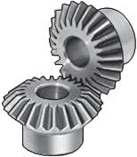
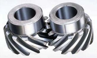
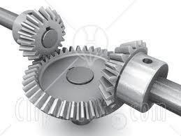
3 Miter Gears Helical Gears KOM/AJM/MECH/N.P.R.C.E.T Page 46


4 Miter Gears-Helical Worm Gears KOM/AJM/MECH/N.P.R.C.E.T Page 47


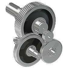
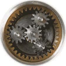
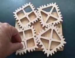
5 Planetary Gears Non-Metal Gears GEAR TRAINS KOM/AJM/MECH/N.P.R.C.E.T Page 48
6 KOM/AJM/MECH/N.P.R.C.E.T Page 49
7 KOM/AJM/MECH/N.P.R.C.E.T Page 50


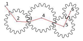
8 Gears are used to change speed in rotational movement. In the example above the blue gear has eleven teeth and the orange gear has twenty five. To turn the orange gear one full turn the blue gear must turn 25/11 or r turns. Notice that as the blue gear turns clockwise the orange gear turns anticlockwise. In the above example the number of teeth on the orange gear is not divisible by the number of teeth on the blue gear. This is deliberate. If the orange gear had thirty three teeth then every three turns of the blue gear the same teeth would mesh together which could cause excessive wear. By using none divisible numbers the same teeth mesh only every seventeen turns of the blue gear. 26. Spur gear Terminology and definitions: Spur Gears: External Internal Definitions 27. Fundamental Law of toothed gearing and Involute gearing: Law of gearing Involutometry and Characteristics of involute action KOM/AJM/MECH/N.P.R.C.E.T Page 51

9 Path of Contact and Arc of Contact Contact Ratio Comparison of involute and cycloidal teeth 28. Inter changeable gears, gear tooth action, Terminology: Inter changeable gears Gear tooth action Terminology 29. Interference and undercutting: Interference in involute gears Methods of avoiding interference Back lash 30. Non standard gear teeth: Helical, Bevel, Worm, Rack and Pinion gears (Basics only) Helical Bevel Worm Rack and Pinion gears Worm Worm gear Worm gears resemble screws. A worm gear is usually meshed with an ordinary looking, disk-shaped gear, which is called the gear, wheel, or worm wheel. Worm-and-gear sets are a simple and compact way to achieve a high torque, low speed gear ratio. For example, helical gears are normally limited to gear ratios of less than 10:1 while worm-and-gear sets vary from 10:1 to 500:1. [ A disadvantage is the potential for considerable sliding action, leading to low efficiency. Worm gears can be considered a species of helical gear, but its helix angle is usually somewhat large (close to 90 degrees) and its body is usually fairly long in the axial KOM/AJM/MECH/N.P.R.C.E.T Page 52


10 direction; and it is these attributes which give it its screw like qualities. The distinction between a worm and a helical gear is made when at least one tooth persists for a full rotation around the helix. If this occurs, it is a 'worm'; if not, it is a 'helical gear'. A worm may have as few as one tooth. If that tooth persists for several turns around the helix, the worm will appear, superficially, to have more than one tooth, but what one in fact sees is the same tooth reappearing at intervals along the length of the worm. The usual screw nomenclature applies: a one-toothed worm is called single thread or single start; a worm with more than one tooth is called multiple thread or multiple start. The helix angle of a worm is not usually specified. Instead, the lead angle, which is equal to 90 degrees minus the helix angle, is given. In a worm-and-gear set, the worm can always drive the gear. However, if the gear attempts to drive the worm, it may or may not succeed. Particularly if the lead angle is small, the gear's teeth may simply lock against the worm's teeth, because the force component circumferential to the worm is not sufficient to overcome friction. Wormand-gear sets that do lock are called self locking, which can be used to advantage, as for instance when it is desired to set the position of a mechanism by turning the worm and then have the mechanism hold that position. An example is the machine head found on some types of stringed instruments. If the gear in a worm-and-gear set is an ordinary helical gear only a single point of contact will be achieved. If medium to high power transmission is desired, the tooth shape of the gear is modified to achieve more intimate contact by making both gears partially envelop each other. This is done by making both concave and joining them at a saddle point; this is called a cone-drive. RACK AND PINION WORM GEAR KOM/AJM/MECH/N.P.R.C.E.T Page 53
11 RACK AND PINION: The rack and pinion is used to convert between rotary and linear motion. The rack is the flat, toothed part, the pinion is the gear. Rack and pinion can convert from rotary to linear of from linear to rotary. The diameter of the gear determines the speed that the rack moves as the pinion turns. Rack and pinions are commonly used in the steering system of cars to convert the rotary motion of the steering wheel to the side to side motion in the wheels. Rack and pinion gears give a positive motion especially compared to the friction drive of a wheel in tarmac. In the rack and pinion railway a central rack between the two rails engages with a pinion on the engine allowing the train to be pulled up very steep slopes. WORM GEAR: A worm is used to reduce speed. For each complete turn of the worm shaft the gear shaft advances only one tooth of the gear. In this case, with a twelve tooth gear, the speed is reduced by a factor of twelve. Also, the axis of rotation is turned by 90 degrees. Unlike ordinary gears, the motion is not reversible, a worm can drive a gear to reduce speed but a gear cannot drive a worm to increase it. As the speed is reduced the power to the drive increases correspondingly. Worm gears are a compact, efficient means of substantially decreasing speed and increasing power. Ideal for use with small electric motors. 31. Gear trains: Gear Train Basics The velocity ratio, m V, of a gear train relates the output velocity to the input velocity. For example, a gear train ratio of 5:1 means that the output gear velocity is 5 times the input gear velocity. 32. Parallel axis gear trains: Simple Gear Trains A simple gear train is a collection of meshing gears where each gear is on its own axis. The train ratio for a simple gear train is the ratio of the number of teeth on the input gear to the number of teeth on the output gear. A simple gear train will typically have 2 or 3 gears and a gear ratio of 10:1 or less. If the train has 3 gears, the intermediate gear has no numerical effect on the train ratio except to change the direction of the output gear. Compound Gear Trains A compound gear train is a train where at least one shaft carries more than one gear. The train ratio is given by the ratio m V = (product of number of teeth on driver gears)/(product of number of teeth on driven gears). A common approach to the design of compound gear trains is to first determine the number of gear reduction steps needed (each step is typically smaller than 10:1 for size purposes). Once this is done, determine KOM/AJM/MECH/N.P.R.C.E.T Page 54

12 the desired ratio for each step, select a pinion size, and then calculate the gear size. Reverted Gear Trains A reverted gear train is a special case of a compound gear train. A reverted gear train has the input and output shafts in line with one another. Assuming no idler gears are used, a reverted gear train can be realized only if the number of teeth on the input side of the train adds up to the same as the number of teeth on the output side of the train. 33. Epicyclic gear trains: If the axis of the shafts over which the gears are mounted are moving relative to a fixed axis, the gear train is called the epicyclic gear train. Problems in epicyclic gear trains. 34. Differentials: Used in the rear axle of an automobile. To enable the rear wheels to revolve at different speeds when negotiating a curve. To enable the rear wheels to revolve at the same speeds when going straight. Rack and pinion Rack and pinion gearing A rack is a toothed bar or rod that can be thought of as a sector gear with an infinitely large radius of curvature. Torque can be converted to linear force by meshing a rack with a pinion: the pinion turns; the rack moves in a straight line. Such a mechanism is used in automobiles to convert the rotation of the steering wheel into the left-to-right motion of the tie rod(s). Racks also feature in the theory of gear geometry, where, for instance, the tooth shape of an interchangeable set of gears may be specified for the rack (infinite radius), and the tooth shapes for gears of particular actual radii then derived from that. The rack and pinion gear type is employed in a rack railway. KOM/AJM/MECH/N.P.R.C.E.T Page 55
 and mechanical differentials.")

13 Epicyclic Epicyclic gearing In epicyclic gearing one or more of the gear axes moves. Examples are sun and planet gearing (see below) and mechanical differentials. Sun and planet Sun (yellow) and planet (red) gearing Main article: Sun and planet gear Sun and planet gearing was a method of converting reciprocal motion into rotary motion in steam engines. It played an important role in the Industrial Revolution. The Sun is yellow, the planet red, the reciprocating crank is blue, the flywheel is green and the driveshaft is grey. KOM/AJM/MECH/N.P.R.C.E.T Page 56

14 Harmonic drive Harmonic drive gearing A harmonic drive is a specialized proprietary gearing mechanism. Cage gear A cage gear, also called a lantern gear or lantern pinion has cylindrical rods for teeth, parallel to the axle and arranged in a circle around it, much as the bars on a round bird cage or lantern. The assembly is held together by disks at either end into which the tooth rods and axle are set. Nomenclature General nomenclature Rotational frequency, n Measured in rotation over time, such as RPM. Angular frequency, ω Measured in radians per second. 1RPM = π / 30 rad/second Number of teeth, N How many teeth a gear has, an integer. In the case of worms, it is the number of thread starts that the worm has. Gear, wheel The larger of two interacting gears. Pinion The smaller of two interacting gears. KOM/AJM/MECH/N.P.R.C.E.T Page 57
15 Path of contact Path followed by the point of contact between two meshing gear teeth. Line of action, pressure line Line along which the force between two meshing gear teeth is directed. It has the same direction as the force vector. In general, the line of action changes from moment to moment during the period of engagement of a pair of teeth. For involute gears, however, the tooth-to-tooth force is always directed along the same line that is, the line of action is constant. This implies that for involute gears the path of contact is also a straight line, coincident with the line of action as is indeed the case. Axis Axis of revolution of the gear; center line of the shaft. Pitch point, p Point where the line of action crosses a line joining the two gear axes. Pitch circle, pitch line Circle centered on and perpendicular to the axis, and passing through the pitch point. A predefined diametral position on the gear where the circular tooth thickness, pressure angle and helix angles are defined. Pitch diameter, d A predefined diametral position on the gear where the circular tooth thickness, pressure angle and helix angles are defined. The standard pitch diameter is a basic dimension and cannot be measured, but is a location where other measurements are made. Its value is based on the number of teeth, the normal module (or normal diametral pitch), and the helix angle. It is calculated as: in metric units or in imperial units. [15] Module, m A scaling factor used in metric gears with units in millimeters who's effect is to enlarge the gear tooth size as the module increases and reduce the size as the module decreases. Module can be defined in the normal (m n ), the transverse (m t ), or the axial planes (m a ) depending on the design approach employed and the type of gear being designed. [15] Module is typically an input value into the gear design and is seldom calculated. Operating pitch diameters KOM/AJM/MECH/N.P.R.C.E.T Page 58
16 Diameters determined from the number of teeth and the center distance at which gears operate. [4] Example for pinion: Pitch surface In cylindrical gears, cylinder formed by projecting a pitch circle in the axial direction. More generally, the surface formed by the sum of all the pitch circles as one moves along the axis. For bevel gears it is a cone. Angle of action Angle with vertex at the gear center, one leg on the point where mating teeth first make contact, the other leg on the point where they disengage. Arc of action Segment of a pitch circle subtended by the angle of action. Pressure angle, θ The complement of the angle between the direction that the teeth exert force on each other, and the line joining the centers of the two gears. For involute gears, the teeth always exert force along the line of action, which, for involute gears, is a straight line; and thus, for involute gears, the pressure angle is constant. Outside diameter, D o Diameter of the gear, measured from the tops of the teeth. Root diameter Diameter of the gear, measured at the base of the tooth. Addendum, a Dedendum, b Radial distance from the pitch surface to the outermost point of the tooth. a = (D o D) / 2 Radial distance from the depth of the tooth trough to the pitch surface. b = (D rootdiameter) / 2 Whole depth, h t The distance from the top of the tooth to the root; it is equal to addendum plus dedendum or to working depth plus clearance. Clearance Distance between the root circle of a gear and the addendum circle of its mate. KOM/AJM/MECH/N.P.R.C.E.T Page 59
17 Working depth Depth of engagement of two gears, that is, the sum of their operating addendums. Circular pitch, p Distance from one face of a tooth to the corresponding face of an adjacent tooth on the same gear, measured along the pitch circle. Diametral pitch, p d Ratio of the number of teeth to the pitch diameter. Could be measured in teeth per inch or teeth per centimeter. Base circle In involute gears, where the tooth profile is the involute of the base circle. The radius of the base circle is somewhat smaller than that of the pitch circle. Base pitch, normal pitch, p b In involute gears, distance from one face of a tooth to the corresponding face of an adjacent tooth on the same gear, measured along the base circle. Interference Contact between teeth other than at the intended parts of their surfaces. Interchangeable set A set of gears, any of which will mate properly with any other. Helical gear nomenclature Helix angle, ψ Angle between a tangent to the helix and the gear axis. Is zero in the limiting case of a spur gear. Normal circular pitch, p n Circular pitch in the plane normal to the teeth. Transverse circular pitch, p Circular pitch in the plane of rotation of the gear. Sometimes just called "circular pitch". p n = pcos(ψ) Several other helix parameters can be viewed either in the normal or transverse planes. The subscript n usually indicates the normal. KOM/AJM/MECH/N.P.R.C.E.T Page 60


18 Worm gear nomenclature Lead Distance from any point on a thread to the corresponding point on the next turn of the same thread, measured parallel to the axis. Linear pitch, p Distance from any point on a thread to the corresponding point on the adjacent thread, measured parallel to the axis. For a single-thread worm, lead and linear pitch are the same. Lead angle, λ Angle between a tangent to the helix and a plane perpendicular to the axis. Note that it is the complement of the helix angle which is usually given for helical gears. Pitch diameter, d w Same as described earlier in this list. Note that for a worm it is still measured in a plane perpendicular to the gear axis, not a tilted plane. Subscript w denotes the worm, subscript g denotes the gear. Tooth contact nomenclature Line of contact Path of action Line of action Plane of action Lines of contact (helical gear) Arc of action Length of action Limit diameter KOM/AJM/MECH/N.P.R.C.E.T Page 61

19 Face advance Zone of action Point of contact Any point at which two tooth profiles touch each other. Line of contact A line or curve along which two tooth surfaces are tangent to each other. Path of action The locus of successive contact points between a pair of gear teeth, during the phase of engagement. For conjugate gear teeth, the path of action passes through the pitch point. It is the trace of the surface of action in the plane of rotation. Line of action The path of action for involute gears. It is the straight line passing through the pitch point and tangent to both base circles. Surface of action The imaginary surface in which contact occurs between two engaging tooth surfaces. It is the summation of the paths of action in all sections of the engaging teeth. Plane of action The surface of action for involute, parallel axis gears with either spur or helical teeth. It is tangent to the base cylinders. Zone of action (contact zone) For involute, parallel-axis gears with either spur or helical teeth, is the rectangular area in the plane of action bounded by the length of action and the effective face width. Path of contact The curve on either tooth surface along which theoretical single point contact occurs during the engagement of gears with crowned tooth surfaces or gears that normally engage with only single point contact. Length of action KOM/AJM/MECH/N.P.R.C.E.T Page 62
20 The distance on the line of action through which the point of contact moves during the action of the tooth profile. Arc of action, Q t The arc of the pitch circle through which a tooth profile moves from the beginning to the end of contact with a mating profile. Arc of approach, Q a The arc of the pitch circle through which a tooth profile moves from its beginning of contact until the point of contact arrives at the pitch point. Arc of recess, Q r The arc of the pitch circle through which a tooth profile moves from contact at the pitch point until contact ends. Contact ratio, m c, ε The number of angular pitches through which a tooth surface rotates from the beginning to the end of contact.in a simple way, it can be defined as a measure of the average number of teeth in contact during the period in which a tooth comes and goes out of contact with the mating gear. Transverse contact ratio, m p, ε α The contact ratio in a transverse plane. It is the ratio of the angle of action to the angular pitch. For involute gears it is most directly obtained as the ratio of the length of action to the base pitch. Face contact ratio, m F, ε β The contact ratio in an axial plane, or the ratio of the face width to the axial pitch. For bevel and hypoid gears it is the ratio of face advance to circular pitch. Total contact ratio, m t, ε γ The sum of the transverse contact ratio and the face contact ratio. ε γ = ε α + ε β m t = m p + m F Modified contact ratio, m o For bevel gears, the square root of the sum of the squares of the transverse and face contact ratios. Limit diameter KOM/AJM/MECH/N.P.R.C.E.T Page 63


21 Diameter on a gear at which the line of action intersects the maximum (or minimum for internal pinion) addendum circle of the mating gear. This is also referred to as the start of active profile, the start of contact, the end of contact, or the end of active profile. Start of active profile (SAP) Intersection of the limit diameter and the involute profile. Face advance Distance on a pitch circle through which a helical or spiral tooth moves from the position at which contact begins at one end of the tooth trace on the pitch surface to the position where contact ceases at the other end. Tooth thickness nomeclature Chordal Tooth thickness Thickness relationships thickness Tooth thickness measurement over pins Span Long and short measurement addendum teeth Circular thickness Length of arc between the two sides of a gear tooth, on the specified datum circle. Transverse circular thickness Circular thickness in the transverse plane. Normal circular thickness KOM/AJM/MECH/N.P.R.C.E.T Page 64
22 Circular thickness in the normal plane. In a helical gear it may be considered as the length of arc along a normal helix. Axial thickness In helical gears and worms, tooth thickness in an axial cross section at the standard pitch diameter. Base circular thickness In involute teeth, length of arc on the base circle between the two involute curves forming the profile of a tooth. Normal chordal thickness Length of the chord that subtends a circular thickness arc in the plane normal to the pitch helix. Any convenient measuring diameter may be selected, not necessarily the standard pitch diameter. Chordal addendum (chordal height) Height from the top of the tooth to the chord subtending the circular thickness arc. Any convenient measuring diameter may be selected, not necessarily the standard pitch diameter. Profile shift Displacement of the basic rack datum line from the reference cylinder, made non-dimensional by dividing by the normal module. It is used to specify the tooth thickness, often for zero backlash. Rack shift Displacement of the tool datum line from the reference cylinder, made nondimensional by dividing by the normal module. It is used to specify the tooth thickness. Measurement over pins Measurement of the distance taken over a pin positioned in a tooth space and a reference surface. The reference surface may be the reference axis of the gear, a datum surface or either one or two pins positioned in the tooth space or spaces opposite the first. This measurement is used to determine tooth thickness. Span measurement Measurement of the distance across several teeth in a normal plane. As long as the measuring device has parallel measuring surfaces that contact on an KOM/AJM/MECH/N.P.R.C.E.T Page 65


23 unmodified portion of the involute, the measurement will be along a line tangent to the base cylinder. It is used to determine tooth thickness. Modified addendum teeth Teeth of engaging gears, one or both of which have non-standard addendum. Full-depth teeth Teeth in which the working depth equals divided by the normal diametral pitch. Stub teeth Teeth in which the working depth is less than divided by the normal diametral pitch. Equal addendum teeth Teeth in which two engaging gears have equal addendums. Long and short-addendum teeth Teeth in which the addendums of two engaging gears are unequal. Pitch nomenclature Pitch is the distance between a point on one tooth and the corresponding point on an adjacent tooth. [4] It is a dimension measured along a line or curve in the transverse, normal, or axial directions. The use of the single word pitch without qualification may be ambiguous, and for this reason it is preferable to use specific designations such as transverse circular pitch, normal base pitch, axial pitch. Pitch Tooth pitch Base pitch relationshipsprincipal pitches Circular pitch, p Arc distance along a specified pitch circle or pitch line between corresponding profiles of adjacent teeth. Transverse circular pitch, p t Circular pitch in the transverse plane. Normal circular pitch, p n, p e KOM/AJM/MECH/N.P.R.C.E.T Page 66
24 Circular pitch in the normal plane, and also the length of the arc along the normal pitch helix between helical teeth or threads. Axial pitch, p x Linear pitch in an axial plane and in a pitch surface. In helical gears and worms, axial pitch has the same value at all diameters. In gearing of other types, axial pitch may be confined to the pitch surface and may be a circular measurement. The term axial pitch is preferred to the term linear pitch. The axial pitch of a helical worm and the circular pitch of its worm gear are the same. Normal base pitch, p N, p bn An involute helical gear is the base pitch in the normal plane. It is the normal distance between parallel helical involute surfaces on the plane of action in the normal plane, or is the length of arc on the normal base helix. It is a constant distance in any helical involute gear. Transverse base pitch, p b, p bt In an involute gear, the pitch on the base circle or along the line of action. Corresponding sides of involute gear teeth are parallel curves, and the base pitch is the constant and fundamental distance between them along a common normal in a transverse plane. Diametral pitch (transverse), P d Ratio of the number of teeth to the standard pitch diameter in inches. Normal diametral pitch, P nd Value of diametral pitch in a normal plane of a helical gear or worm. Angular pitch, θ N, τ Angle subtended by the circular pitch, usually expressed in radians. degrees or radians Backlash Main article: Backlash (engineering) Backlash is the error in motion that occurs when gears change direction. It exists because there is always some gap between the trailing face of the driving tooth and the leading face of the tooth behind it on the driven gear, and that gap must be closed before force can be transferred in the new direction. The term "backlash" can also be used to refer to the size of the gap, not just the phenomenon it causes; thus, one could KOM/AJM/MECH/N.P.R.C.E.T Page 67
25 speak of a pair of gears as having, for example, "0.1 mm of backlash." A pair of gears could be designed to have zero backlash, but this would presuppose perfection in manufacturing, uniform thermal expansion characteristics throughout the system, and no lubricant. Therefore, gear pairs are designed to have some backlash. It is usually provided by reducing the tooth thickness of each gear by half the desired gap distance. In the case of a large gear and a small pinion, however, the backlash is usually taken entirely off the gear and the pinion is given full sized teeth. Backlash can also be provided by moving the gears farther apart. For situations, such as instrumentation and control, where precision is important, backlash can be minimised through one of several techniques. For instance, the gear can be split along a plane perpendicular to the axis, one half fixed to the shaft in the usual manner, the other half placed alongside it, free to rotate about the shaft, but with springs between the two halves providing relative torque between them, so that one achieves, in effect, a single gear with expanding teeth. Another method involves tapering the teeth in the axial direction and providing for the gear to be slid in the axial direction to take up slack. Shifting of gears In some machines (e.g., automobiles) it is necessary to alter the gear ratio to suit the task. There are several methods of accomplishing this. For example: Manual transmission Automatic gearbox Derailleur gears which are actually sprockets in combination with a roller chain Hub gears (also called epicyclic gearing or sun-and-planet gears) There are several outcomes of gear shifting in motor vehicles. In the case of air pollution emissions, there are higher pollutant emissions generated in the lower gears, when the engine is working harder than when higher gears have been attained. In the case of vehicle noise emissions, there are higher sound levels emitted when the vehicle is engaged in lower gears. This fact has been utilized in analyzing vehicle generated sound since the late 1960s, and has been incorporated into the simulation of KOM/AJM/MECH/N.P.R.C.E.T Page 68
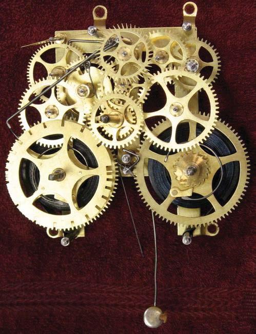
26 urban roadway noise and corresponding design of urban noise barriers along roadways. Tooth profile Profile of a spur gear Undercut A profile is one side of a tooth in a cross section between the outside circle and the root circle. Usually a profile is the curve of intersection of a tooth surface and a plane or surface normal to the pitch surface, such as the transverse, normal, or axial plane. The fillet curve (root fillet) is the concave portion of the tooth profile where it joins the bottom of the tooth space. 2 As mentioned near the beginning of the article, the attainment of a non fluctuating velocity ratio is dependent on the profile of the teeth. Friction and wear between two gears is also dependent on the tooth profile. There are a great many tooth profiles that will give a constant velocity ratio, and in many cases, given an arbitrary tooth shape, it is possible to develop a tooth profile for the mating gear that will give a constant velocity ratio. However, two constant velocity tooth profiles have been by far the most commonly used in modern times. They are the cycloid and the involute. The cycloid was more common until the late 1800s; since then the involute has largely superseded it, particularly in drive train applications. The cycloid is in some ways the more interesting and flexible shape; however the involute has two advantages: it is easier to manufacture, and it permits the center to center spacing of the gears to vary over some range without ruining the constancy of the velocity ratio. Cycloidal gears only work properly if the center spacing is exactly right. Cycloidal gears are still used in mechanical clocks. KOM/AJM/MECH/N.P.R.C.E.T Page 69
27 An undercut is a condition in generated gear teeth when any part of the fillet curve lies inside of a line drawn tangent to the working profile at its point of juncture with the fillet. Undercut may be deliberately introduced to facilitate finishing operations. With undercut the fillet curve intersects the working profile. Without undercut the fillet curve and the working profile have a common tangent. Formulae used: i)addendum = πm/4 ii)pitch circle radius of pinion,r = m Tp/2 iii)pitch circle radii of Gear wheel,r= mta/2 iv)addendum radius of gear wheel,ra =R+Addendum v)length of path of contact,kl = KP+ PL vi) Length of arc of contact = KL / cos Φ vii) Number of teeth in contact = length of arc of contact / Circular pitch (P c) KOM/AJM/MECH/N.P.R.C.E.T Page 70
GEAR CONTENTS POWER TRANSMISSION GEAR TYPES OF GEARS NOMENCLATURE APPLICATIONS OF GEARS VELOCITY RATIO GEAR TRAINS EXAMPLE PROBLEMS AND QUESTIONS
 GEAR CONTENTS POWER TRANSMISSION GEAR TYPES OF GEARS NOMENCLATURE APPLICATIONS OF GEARS VELOCITY RATIO GEAR TRAINS EXAMPLE PROBLEMS AND QUESTIONS GEAR.. Power transmission is the movement of energy from
(POWER TRANSMISSION Methods)
") UNIT-5 (POWER TRANSMISSION Methods) It is a method by which you can transfer cyclic motion from one place to another or one pulley to another pulley. The ways by which we can transfer cyclic motion are:-
UNIT-5 (POWER TRANSMISSION Methods) It is a method by which you can transfer cyclic motion from one place to another or one pulley to another pulley. The ways by which we can transfer cyclic motion are:-
Part VII: Gear Systems: Analysis
 Part VII: Gear Systems: Analysis This section will review standard gear systems and will provide the basic tools to perform analysis on these systems. The areas covered in this section are: 1) Gears 101:
Introduction. Kinematics and Dynamics of Machines. Involute profile. 7. Gears
 Introduction The kinematic function of gears is to transfer rotational motion from one shaft to another Kinematics and Dynamics of Machines 7. Gears Since these shafts may be parallel, perpendicular, or
Instantaneous Centre Method
 Instantaneous Centre Method The combined motion of rotation and translation of the link AB may be assumed to be a motion of pure rotation about some centre I, known as the instantaneous centre of rotation.
Catalog Q Conversion For those wishing to ease themselves into working with metric gears
 1.3.4 Conversion For those wishing to ease themselves into working with metric gears by looking at them in terms of familiar inch gearing relationships and mathematics, Table 1-5 is offered as a means
Gear Tooth Geometry - This is determined primarily by pitch, depth and pressure angle
 Gear Tooth Geometry - This is determined primarily by pitch, depth and pressure angle Addendum: The radial distance between the top land and the pitch circle. Addendum Circle: The circle defining the outer
CH#13 Gears-General. Drive and Driven Gears 3/13/2018
 CH#13 Gears-General A toothed wheel that engages another toothed mechanism in order to change the speed or direction of transmitted motion The gear set transmits rotary motion and force. Gears are used
UNIT -I. Ans: They are specified by the no. of strands & the no. of wires in each strand.
 VETRI VINAYAHA COLLEGE OF ENGINEERING AND TECHNOLOGY, THOTTIAM, NAMAKKAL-621215. DEPARTMENT OF MECHANICAL ENGINEERING SIXTH SEMESTER / III YEAR ME6601 DESIGN OF TRANSMISSION SYSTEM (Regulation-2013) UNIT
1/2/2015 2:04 PM. Chapter 13. Gears General. Dr. Mohammad Suliman Abuhaiba, PE
 Chapter 13 Gears General 1 2 Chapter Outline 1. Types of Gears 2. Nomenclature 3. Conjugate Action 4. Involute Properties 5. Fundamentals 6. Contact Ratio 7. Interference 8. The Forming of Gear Teeth 9.
12/6/2013 9:09 PM. Chapter 13. Gears General. Dr. Mohammad Suliman Abuhaiba, PE
 Chapter 13 Gears General 1 2 Chapter Outline 1. Types of Gears 2. Nomenclature 3. Conjugate Action 4. Involute Properties 5. Fundamentals 6. Contact Ratio 7. Interference 8. The Forming of Gear Teeth 9.
What are the functions of gears? What is gear?
 8//0 hapter seven Laith atarseh are very important in power transmission between a drive rotor and driven rotor What are the functions of gears? - Transmit motion and torque (power) between shafts - Maintain
ME6601 DESIGN OF TRANSMISSION SYSTEMS
 SYED AMMAL ENGINEERING COLLEGE (Approved by the AICTE, New Delhi, Govt. of Tamilnadu and Affiliated to Anna University, Chennai) Established in 1998 - An ISO 9001:2008 Certified Institution Dr. E.M.Abdullah
Lecture (7) on. Gear Measurement. By Dr. Emad M. Saad. Industrial Engineering Dept. Faculty of Engineering. Fayoum University.
 on. Gear Measurement. By Dr. Emad M. Saad. Industrial Engineering Dept. Faculty of Engineering. Fayoum University.") 1 Lecture (7) on Gear Measurement Fayoum University By Dr. Emad M. Saad Industrial Engineering Dept. Faculty of Engineering Fayoum University Faculty of Engineering Industrial Engineering Dept. 2015-2016
1 Lecture (7) on Gear Measurement Fayoum University By Dr. Emad M. Saad Industrial Engineering Dept. Faculty of Engineering Fayoum University Faculty of Engineering Industrial Engineering Dept. 2015-2016
Chapter seven. Gears. Laith Batarseh
 Chapter seven Gears Laith Batarseh Gears are very important in power transmission between a drive rotor and driven rotor What are the functions of gears? - Transmit motion and torque (power) between shafts
Different types of gears. Spur gears. Idler gears. Worm gears. Bevel gears. Belts & Pulleys
 GEARS Robot Gears By using different gear diameters, you can exchange between rotational (or translation) velocity and torque. by looking at the motor datasheet you can determine the output velocity and
ME6401 KINEMATICS OF MACHINERY UNIT- I (Basics of Mechanism)
") ME6401 KINEMATICS OF MACHINERY UNIT- I (Basics of Mechanism) 1) Define resistant body. 2) Define Link or Element 3) Differentiate Machine and Structure 4) Define Kinematic Pair. 5) Define Kinematic Chain.
ME6401 KINEMATICS OF MACHINERY UNIT- I (Basics of Mechanism) 1) Define resistant body. 2) Define Link or Element 3) Differentiate Machine and Structure 4) Define Kinematic Pair. 5) Define Kinematic Chain.
 DEPARTMENT OF MECHANICAL ENGINEERING Subject code: ME6601 Subject Name: DESIGN OF TRANSMISSION SYSTEMS UNIT-I DESIGN OF TRANSMISSION SYSTEMS FOR FLEXIBLE ELEMENTS 1. What is the effect of centre distance
Chapter 8 Kinematics of Gears
 Chapter 8 Kinematics of Gears Gears! Gears are most often used in transmissions to convert an electric motor s high speed and low torque to a shaft s requirements for low speed high torque: Speed is easy
Engineering Information
 Engineering nformation Gear Nomenclature ADDENDUM (a) is the height by which a tooth projects beyond the pitch circle or pitch line. BASE DAMETER (D b ) is the diameter of the base cylinder from which
11. GEAR TRANSMISSIONS
 11. GEAR TRANSMISSIONS 11.1. GENERAL CONSIDERATIONS Gears are one of the most important elements used in machinery. There are few mechanical devices that do not have the need to transmit power and motion
Basic Fundamentals of Gear Drives
 Basic Fundamentals of Gear Drives Course No: M06-031 Credit: 6 PDH A. Bhatia Continuing Education and Development, Inc. 9 Greyridge Farm Court Stony Point, NY 10980 P: (877) 322-5800 F: (877) 322-4774
St.MARTIN S ENGINEERING COLLEGE Dhulapally, Secunderabad
 St.MARTIN S ENGINEERING COLLEGE Dhulapally, Secunderabad-500 014 Subject: Kinematics of Machines Class : MECH-II Group A (Short Answer Questions) UNIT-I 1 Define link, kinematic pair. 2 Define mechanism
KINEMATICS OF MACHINARY UBMC302 QUESTION BANK UNIT-I BASICS OF MECHANISMS PART-A
 KINEMATICS OF MACHINARY UBMC302 QUESTION BANK UNIT-I BASICS OF MECHANISMS PART-A 1. Define the term Kinematic link. 2. Classify kinematic links. 3. What is Mechanism? 4. Define the terms Kinematic pair.
CHAPTER 6 GEARS CHAPTER LEARNING OBJECTIVES
 CHAPTER 6 GEARS CHAPTER LEARNING OBJECTIVES Upon completion of this chapter, you should be able to do the following: Compare the types of gears and their advantages. Did you ever take a clock apart to
Chapter 3. Transmission Components
 Chapter 3. Transmission Components The difference between machine design and structure design An important design problem in a mechanical system is how to transmit and convert power to achieve required
SECTION 4 SPUR GEAR CALCULATIONS
 Function of α, or invα, is known as involute function. Involute function is very important in gear design. Involute function values can be obtained from appropriate tables. With the 3.1 Contact Ratio center
1. (a) Discuss various types of Kinematic links with examples. (b) Explain different types of constrained motions with examples.
 Discuss various types of Kinematic links with examples. (b) Explain different types of constrained motions with examples.") Code No: RR310304 Set No. 1 III B.Tech I Semester Supplementary Examinations, February 2007 KINEMATICS OF MACHINERY ( Common to Mechanical Engineering, Mechatronics and Production Engineering) Time: 3
Code No: RR310304 Set No. 1 III B.Tech I Semester Supplementary Examinations, February 2007 KINEMATICS OF MACHINERY ( Common to Mechanical Engineering, Mechatronics and Production Engineering) Time: 3
T25 T25 T25 T27 T27 T28 T28 T28 T28 T29 T29 T29 T31 T37 T37 T38 T T T48
 1.0 INTRODUCTION 2.0 BASIC GEOMETRY OF SPUR GEARS 2.1 Basic Spur Gear Geometry 2.2 The Law of Gearing 2.3 The Involute Curve 2.4 Pitch Circles 2.5 Pitch 2.5.1 Circular Pitch 2.5.2 Diametral Pitch 2.5.3
KINGS COLLEGE OF ENGINEERING DEPARTMENT OF MECHANICAL ENGINEERING
 KINGS COLLEGE OF ENGINEERING DEPARTMENT OF MECHANICAL ENGINEERING QUESTION BANK Sub Code/Name: ME 1352 DESIGN OF TRANSMISSION SYSTEMS Year/Sem: III / VI UNIT-I (Design of transmission systems for flexible
1.6 Features of common gears
 1.6 Features of common gears Chapter 1.2 covered briefly on types of gear. The main gear features are explained here. Helical gear Helical gear has characteristics of transferability of larger load, less
SYED AMMAL ENGINEERING COLLEGE
 SYED AMMAL ENGINEERING COLLEGE (Approved by the AICTE, New Delhi, Govt. of Tamilnadu and Affiliated to Anna University, Chennai) Established in 1998 - An ISO 9001:2000 Certified Institution Dr. E.M.Abdullah
BRCM COLLEGE OF ENGINEERING & TECHNOLOGY BAHAL, BHIWANI Practical Experiment Instructions Sheet
 BRCM COLLEGE OF KOM ME- 212 F KINEMATICS OF MACHINES LAB BRANCH-ME List of Experiments : 1. To study various types of Kinematic links, pairs, chains and Mechanisms. 2. To study inversions of 4 Bar Mechanisms,
Moments. It doesn t fall because of the presence of a counter balance weight on the right-hand side. The boom is therefore balanced.
 Moments The crane in the image below looks unstable, as though it should topple over. There appears to be too much of the boom on the left-hand side of the tower. It doesn t fall because of the presence
Metrology Prof. Dr Kanakuppi Sadashivappa Bapuji Institute of Engineering and Technology Davangere. Lecture 25 Introduction of Gears
 Metrology Prof. Dr Kanakuppi Sadashivappa Bapuji Institute of Engineering and Technology Davangere Lecture 25 Introduction of Gears I welcome you for the series of lecture on gear measurement and at module
Gear Measurement. Lecture (7) Mechanical Measurements
 Mechanical Measurements") 18 3. Gear profile checking 2. Involute measuring machine In this method the gear is held on a mandrel and circular disc of same diameter as the base circle of gear for the measurement is fixed on the
18 3. Gear profile checking 2. Involute measuring machine In this method the gear is held on a mandrel and circular disc of same diameter as the base circle of gear for the measurement is fixed on the
 DEPARTMENT OF MECHANICAL ENGINEERING ME6401- KINEMATICS OF MACHINERY QUESTION BANK Part-A Unit 1-BASICS OF MECHANISMS 1. Define degrees of freedom. 2. What is meant by spatial mechanism? 3. Classify the
2. a) What is pantograph? What are its uses? b) Prove that the peaucellier mechanism generates a straight-line motion. (5M+10M)
 What is pantograph? What are its uses? b) Prove that the peaucellier mechanism generates a straight-line motion. (5M+10M)") Code No: R22032 R10 SET - 1 1. a) Define the following terms? i) Link ii) Kinematic pair iii) Degrees of freedom b) What are the inversions of double slider crank chain? Describe any two with neat sketches.
Code No: R22032 R10 SET - 1 1. a) Define the following terms? i) Link ii) Kinematic pair iii) Degrees of freedom b) What are the inversions of double slider crank chain? Describe any two with neat sketches.
SECTION 8 BEVEL GEARING
 SECTION 8 BEVEL GEARING For intersecting shafts, bevel gears offer a good means of transmitting motion and power. Most transmissions occur at right angles, Figure 8-1, but the shaft angle can be any value.
 VALLIAMMAI ENGINEERING COLLEGE DEPARTMENT OF MECHANICAL ENGINEERING ME6401- KINEMATICS OF MACHINERY QUESTION BANK PART-A Unit 1-BASICS OF MECHANISMS 1. Define degrees of freedom. BT1 2. Describe spatial
TECHNOLOGY MECHANISMS
 TECHNOLOGY MECHANISMS 3º ESO IES CHAN DO MONTE URTAZA 1 WHAT IS A MECHANISM? Mechanism are devices that have been designed to make jobs easier. They all have certain things in common: They involve some
Code No: R Set No. 1
 Code No: R05310304 Set No. 1 III B.Tech I Semester Regular Examinations, November 2007 KINEMATICS OF MACHINERY ( Common to Mechanical Engineering, Mechatronics, Production Engineering and Automobile Engineering)
Spur Gears. Helical Gears. Bevel Gears. Worm Gears
 Spur s General: Spur gears are the most commonly used gear type. They are characterized by teeth which are perpendicular to the face of the gear. Spur gears are by far the most commonly available, and
Copyright Notice. Small Motor, Gearmotor and Control Handbook Copyright Bodine Electric Company. All rights reserved.
 Copyright Notice Small Motor, Gearmotor and Control Handbook Copyright 1993-2003 Bodine Electric Company. All rights reserved. Unauthorized duplication, distribution, or modification of this publication,
Chapter 10 Machine elements. Bachelor Program in AUTOMATION ENGINEERING Prof. Rong-yong Zhao Second Semester,
 Chapter 10 Machine elements Bachelor Program in AUTOMATION ENGINEERING Prof. Rong-yong Zhao (zhaorongyong@tongji.edu.cn) Second Semester,2013-2014 Content 10.1 Cams 10.1.1- Synthesis of the mechanism 10.1.2-
Graphical representation of a gear
 Homework 4 Gears Gears are designed to transmit rotary motion. Often they are arranged in a gear train (meshed together). Gear trains provide a change in speed, torque (turning force) and direction (clockwise
Theory of Machines. CH-1: Fundamentals and type of Mechanisms
 CH-1: Fundamentals and type of Mechanisms 1. Define kinematic link and kinematic chain. 2. Enlist the types of constrained motion. Draw a label sketch of any one. 3. Define (1) Mechanism (2) Inversion
GEARING. Theory of. Stephen. Kinetics, Geometry, and Synthesis. P. Radzevich. /Ov CRC Press yc*** J Taylor& Francis Croup Boca Raton
 Theory of GEARING Kinetics, Geometry, and Synthesis Stephen P. Radzevich /Ov CRC Press yc*** J Taylor& Francis Croup Boca Raton London New York CRC Press is an imprint of the Taylor & Francis Group, an
DUDLEY'S" HANDBOOK OF PRACTICAL GEAR DESIGN AND MANUFACTURE. Stephen P. Radzevich
 Second Edition DUDLEY'S" HANDBOOK OF PRACTICAL GEAR DESIGN AND MANUFACTURE Stephen P. Radzevich LßP) CRC Press VV J Taylors Francis Group Boca Raton London New York CRC Press is an imprint of the Taylor
Gearheads H-51. Gearheads for AC Motors H-51
 Technical Reference H-51 for AC Since AC motor gearheads are used continuously, primarily for transmitting power, they are designed with priority on ensuring high permissible torque, long life, noise reduction
Gear Engineering Data. Spur Gear Gear Formulas Drive Selection Horsepower and Torque Tables
 Engineering Gear Engineering Data Spur Gear Gear Formulas Drive Selection Horsepower and Torque Tables G-79 Gear Selection Stock Spur Gear Drive Selection When designing a stock gear drive using the horsepower
11/23/2013. Chapter 13. Gear Trains. Dr. Mohammad Suliman Abuhiba, PE
 Chapter 13 Gear Trains 1 2 13.2. Types of Gear Trains 1. Simple gear train 2. Compound gear train 3. Reverted gear train 4. Epicyclic gear train: axes of shafts on which the gears are mounted may move
CHENDU COLLEGE OF ENGINEERING & TECHNOLOGY DEPARTMENT OF MECHANICAL ENGINEERING QUESTION BANK IV SEMESTER
 CHENDU COLLEGE OF ENGINEERING & TECHNOLOGY DEPARTMENT OF MECHANICAL ENGINEERING QUESTION BANK IV SEMESTER Sub Code: ME 6401 KINEMATICS OF MACHINERY UNIT-I PART-A 1. Sketch and define Transmission angle
Lecture 13 BEVEL GEARS
 Lecture 13 BEVEL GEARS CONTENTS 1. Bevel gear geometry and terminology 2. Bevel gear force analysis 3. Bending stress analysis 4. Contact stress analysis 5. Permissible bending fatigue stress 6. Permissible
MECHANICAL DRIVES 1 SPUR GEAR DRIVES LEARNING ACTIVITY PACKET BB502-XD06AEN
 MECHANICAL DRIVES 1 LEARNING ACTIVITY PACKET SPUR GEAR DRIVES BB502-XD06AEN LEARNING ACTIVITY PACKET 6 SPUR GEAR DRIVES INTRODUCTION This LAP will begin the study of the third type of adjacent shaft-to-shaft
The Geometry of Involute Gears
 The Geometry of Involute Gears J.R. Colbourne The Geometry of Involute Gears With 217 Illustrations Springer-Verlag New York Berlin Heidelberg London Paris Tokyo J.R. Colbourne Department of Mechanical
Driver Driven. InputSpeed. Gears
 Gears Gears are toothed wheels designed to transmit rotary motion and power from one part of a mechanism to another. They are fitted to shafts with special devices called keys (or splines) that ensure
Chain Drives. Pitch. Basic Types -There are six major types of power-
 1 2 Power transmission chains have two things in common; side bars or link plates, and pin and bushing joints. The chain articulates at each joint to operate around a toothed sprocket. The pitch of the
Simple Gears and Transmission
 Simple Gears and Transmission Simple Gears and Transmission page: of 4 How can transmissions be designed so that they provide the force, speed and direction required and how efficient will the design be?
we will learn how to conduct force and torque analysis on gears in order to calculate bearing
 8.1 Introduction to Gears Gears are used to transmit motion and torque from one shaft to another. In this section we will discuss the kinematics of gears; that is, the motion relationships between gears.
Effect of Geometry Factor I & J Factor Multipliers in the performance of Helical Gears
 Effect of Geometry Factor I & J Factor Multipliers in the performance of Helical Gears 1 Amit D. Modi, 2 Manan B. Raval, 1 Lecturer, 2 Lecturer, 1 Department of Mechanical Engineering, 2 Department of
Design of Helical Gear and Analysis on Gear Tooth
 Design of Helical Gear and Analysis on Gear Tooth Indrale Ratnadeep Ramesh Rao M.Tech Student ABSTRACT Gears are mainly used to transmit the power in mechanical power transmission systems. These gears
Sheet 1 Variable loading
 Sheet 1 Variable loading 1. Estimate S e for the following materials: a. AISI 1020 CD steel. b. AISI 1080 HR steel. c. 2024 T3 aluminum. d. AISI 4340 steel heat-treated to a tensile strength of 1700 MPa.
FIRSTRANKER. 2. (a) Distinguish (by neat sketches) betweenpeaucellier mechanism and Hart mechanism.
 Distinguish (by neat sketches) betweenpeaucellier mechanism and Hart mechanism.") Code No: 07A51404 R07 Set No. 2 IIIB.Tech I Semester Examinations,May 2011 KINEMATICS OF MACHINERY Mechatronics Time: 3 hours Max Marks: 80 Answer any FIVE Questions All Questions carry equal marks 1.
Code No: 07A51404 R07 Set No. 2 IIIB.Tech I Semester Examinations,May 2011 KINEMATICS OF MACHINERY Mechatronics Time: 3 hours Max Marks: 80 Answer any FIVE Questions All Questions carry equal marks 1.
 Lecture plan UNIT I Basics of Mechanisms SYLLABUS Introduction: Definitions : Link or Element, Pairing of Elements with degrees of freedom, Grubler s criterion (without derivation), Kinematic chain, Mechanism,
Bibliography. [1] Buckingham, Earle: "Analytical Mechanics of Gears", McGraw-Hill, New York, 1949, and republished by Dover, New York, 1963.
![Bibliography. [1] Buckingham, Earle: Analytical Mechanics of Gears, McGraw-Hill, New York, 1949, and republished by Dover, New York, 1963.](/thumbs/87/96820687.jpg "Bibliography. [1] Buckingham, Earle: Analytical Mechanics of Gears, McGraw-Hill, New York, 1949, and republished by Dover, New York, 1963.") Bibliography The first five references listed are books on gearing. Some of them deal not only with the geometry, but also with many other aspects of gearing. However, the books are included in this bibliography
Bibliography The first five references listed are books on gearing. Some of them deal not only with the geometry, but also with many other aspects of gearing. However, the books are included in this bibliography
Simple Gears and Transmission
 Simple Gears and Transmission Contents How can transmissions be designed so that they provide the force, speed and direction required and how efficient will the design be? Initial Problem Statement 2 Narrative
Code No: R Set No. 1
 Code No: R05222106 Set No. 1 II B.Tech II Semester Supplimentary Examinations, Aug/Sep 2007 MECHANISMS AND MECHANICAL DESIGN (Aeronautical Engineering) Time: 3 hours Max Marks: 80 Answer any FIVE Questions
Program Internal Gear Set Profile Shift Coefficients With Zero Backlash Introduction
 Program 60-107 Internal Gear Set Profile Shift Coefficients With Zero Backlash Introduction The purpose of this model is to provide data for a gear set when the tooth thickness and/or the center distance
Bevel Gears n A Textbook of Machine Design
 080 n A Textbook of Machine Design C H A P T E R 30 Bevel Gears. Introduction.. Classification of Bevel Gears. 3. Terms used in Bevel Gears. 4. Determination of Pitch Angle for Bevel Gears. 5. Proportions
INSTITUTE OF AERONAUTICAL ENGINEERING
 INSTITUTE OF AERONAUTICAL ENGINEERING (Autonomous) Dundigal, Hyderabad -500 043 Course Name Course Code Class Branch MECHANICAL ENGINEERING TUTORIAL QUESTION BANK 2015 2016 : KINEMATICS OF MACHINES : A40309
Model Library Power Transmission
 Model Library Power Transmission The Power Transmission libraries in SimulationX support the efficient modeling and analysis of mechanical powertrains as well as the simulation-based design of controlled
Bevel Gears. Fig.(1) Bevel gears
 Bevel gears") Bevel Gears Bevel gears are cut on conical blanks to be used to transmit motion between intersecting shafts. The simplest bevel gear type is the straighttooth bevel gear or straight bevel gear as can be
Bevel Gears Bevel gears are cut on conical blanks to be used to transmit motion between intersecting shafts. The simplest bevel gear type is the straighttooth bevel gear or straight bevel gear as can be
INVOLUTE SPIRAL FACE COUPLINGS AND GEARS: DESIGN APPROACH AND MANUFACTURING TECHNIQUE
 УДК 621.9.015 Dr. Alexander L. Kapelevich, Stephen D. Korosec 38 INVOLUTE SPIRAL FACE COUPLINGS AND GEARS: DESIGN APPROACH AND MANUFACTURING TECHNIQUE This paper presents spiral face gears with an involute
Transmission systems: Multiple components that have the same type of movement (rotational, linear, etc)
") Transmission systems: Multiple components that have the same type of movement (rotational, linear, etc) Transformation systems: Different components in the system have different types of movement Ex: rotational
Transmission systems: Multiple components that have the same type of movement (rotational, linear, etc) Transformation systems: Different components in the system have different types of movement Ex: rotational
CHENDU COLLEGE OF ENGINEERING & TECHNOLOGY DEPARTMENT OF MECHANICAL ENGINEERING QUESTION BANK
 CHENDU COLLEGE OF ENGINEERING & TECHNOLOGY DEPARTMENT OF MECHANICAL ENGINEERING QUESTION BANK Sub Code: ME 2342 DESIGN OF TRANSMISSION SYSTEM UNIT - I 1. How the bevel gears are classified? Explain with
CLASSIFICATION OF ROLLING-ELEMENT BEARINGS
 CLASSIFICATION OF ROLLING-ELEMENT BEARINGS Ball bearings can operate at higher speed in comparison to roller bearings because they have lower friction. In particular, the balls have less viscous resistance
ISO INTERNATIONAL STANDARD. Bevel and hypoid gear geometry. Géométrie des engrenages coniques et hypoïdes. First edition
 INTERNATIONAL STANDARD ISO 23509 First edition 2006-09-01 Bevel and hypoid gear geometry Géométrie des engrenages coniques et hypoïdes Reference number ISO 2006 Provläsningsexemplar / Preview PDF disclaimer
1 135 teeth to rack
 1. A spur gear with 46 teeth, 2.5 module has to be cut on a column and knee type horizontal milling machine with a rotary disc type form gear milling cutter. The 2.5 module cutter no. 3 is used on a blank
Marine Engineering Exam Resource Review of Couplings
 1. What are rigid couplings used for? Used to join drive shafts together. True alignment and rigidity are required. Example Drive shafts and production lines, bridge cranes, solid shaft that needs to be
R10 Set No: 1 ''' ' '' '' '' Code No: R31033
 R10 Set No: 1 III B.Tech. I Semester Regular and Supplementary Examinations, December - 2013 DYNAMICS OF MACHINERY (Common to Mechanical Engineering and Automobile Engineering) Time: 3 Hours Max Marks:
All levers are one of three types, usually called classes. The class of a lever depends on the relative position of the load, effort and fulcrum:
 Página 66 de 232 Mechanisms A mechanism is simply a device which takes an input motion and force, and outputs a different motion and force. The point of a mechanism is to make the job easier to do. The
Machines and mechanisms
 Machines and mechanisms Contents: 1. Basics and Kinematics of Mechanism 2. Cam and Follower 3. Governor 4. Gear and Gear Train 5. Inertia Force Analysis Basics and Kinematics Mechanism: 1. A rigid body
III B.Tech I Semester Supplementary Examinations, May/June
 Set No. 1 III B.Tech I Semester Supplementary Examinations, May/June - 2015 1 a) Derive the expression for Gyroscopic Couple? b) A disc with radius of gyration of 60mm and a mass of 4kg is mounted centrally
Introduction to Gear Design
 Introduction to Gear Design Course No: M03-016 Credit: 3 PDH Robert P. Tata, P.E. Continuing Education and Development, Inc. 9 Greyridge Farm Court Stony Point, NY 10980 P: (877) 322-5800 F: (877) 322-4774
1.8 Rack shift of the gear
 1.8 Rack shift of the gear Undercut When Number of teeth is belo minimum as shon in Fig. 3, part of dedendum is no longer an Involute curve but ill look like a shape scooped out by cutter tool. Refer to
Spiroid High Torque Skew Axis Gearing A TECHNICAL PRIMER F. EVERTZ, M. GANGIREDDY, B. MORK, T. PORTER & A. QUIST
 2016 Spiroid High Torque Skew Axis Gearing A TECHNICAL PRIMER F. EVERTZ, M. GANGIREDDY, B. MORK, T. PORTER & A. QUIST Table of Contents INTRODUCTION PAGE 02 SPIROID GEAR SET CHARACTERISTICS PAGE 03 BASIC
Finite element analysis of profile modified spur gear
 Finite element analysis of profile modified spur gear Sagar Gaur Mechanical Engineering Department, Institute of Technology, YashluvVirwani Mechanical Engineering Department, Institute of Technology, Rudresh
Tribology Aspects in Angular Transmission Systems
 Tribology Aspects in Angular Transmission Systems Part II Straight Bevel Gears Dr. Hermann Stadtfeld (This is the second of an eight-part series on the tribology aspects of angular gear drives. Each article
MECHANISMS. AUTHORS: Santiago Camblor y Pablo Rivas INDEX
 MECHANISMS AUTHORS: Santiago Camblor y Pablo Rivas INDEX 1 INTRODUCTION 2 LEVER 3 PULLEYS 4 BELT AND PULLEY SYSTEM 5 GEARS 6 GEARS WITH CHAIN 7 WORM GEAR 8 RACK AND PINION 9 SCREW AND NUT 10 CAM 11 ECCENTRIC
CHAPTER 5 PREVENTION OF TOOTH DAMAGE IN HELICAL GEAR BY PROFILE MODIFICATION
 90 CHAPTER 5 PREVENTION OF TOOTH DAMAGE IN HELICAL GEAR BY PROFILE MODIFICATION 5.1 INTRODUCTION In any gear drive the absolute and the relative transmission error variations normally increases with an
Hours / 100 Marks Seat No.
 17412 16117 3 Hours / 100 Seat No. Instructions (1) All Questions are Compulsory. (2) Answer each next main Question on a new page. (3) Illustrate your answers with neat sketches wherever necessary. (4)
FRICTION DEVICES: DYNAMOMETER. Presented by: RONAK D. SONI Assistant Professor Parul Institute of Technology, Parul University
 FRICTION DEVICES: DYNAMOMETER Presented by: RONAK D. SONI Assistant Professor Parul Institute of Technology, Parul University DYNAMOMETER A dynamometer is a brake but in addition it has a device to measure
1.7 Backlash. Summary of the backlash is play or clearance between one pair of gear. Fig. 17 Backlash
 1.7 Backlash Summary of the backlash is play or clearance between one pair of gear. Fig. 17 Backlash Great care is taken to produce the gear with zero deviation. However we are unable to completely eliminate
A Study on Noncircular Gears with Non-Uniform Teeth
 A Study on Noncircular Gears with Non-Uniform Teeth Kazushi Kumagai* 1 and Tetsuya Oizumi* *1 Department of Infomation System, Sendai National College of Technology 4-16-1 Ayashi-Chuo, Aoba-ku, Sendai
12/25/2015. Chapter 20. Cams. Mohammad Suliman Abuhiba, Ph.D., PE
 Chapter 20 Cams 1 2 Introduction A cam: a rotating machine element which gives reciprocating or oscillating motion to another element (follower) Cam & follower have a line constitute a higher pair. of
DHANALAKSHMI COLLEGE OF ENGINEERING
 DHANALAKSHMI COLLEGE OF ENGINEERING (Dr.VPR Nagar, Manimangalam, Tambaram) Chennai - 601 301 DEPARTMENT OF MECHANICAL ENGINEERING III YEAR MECHANICAL - VI SEMESTER ME 6601 DESIGN OF TRANSMISSION SYSTEMS
What is a Mechanism?
 Mechanisms What is a Mechanism? A mechanism is the part of a machine which contains two or more pieces arranged so that the motion of one compels the motion of the others. Generally used to: Change the
Design and Fabrication of Shaft Drive for two Wheelers
 International OPEN ACCESS Journal Of Modern Engineering Research (IJMER) Design and Fabrication of Shaft Drive for two Wheelers K.Vinoth Kumar 1, Kari Naga Nikhil, Kakollu Manoj Kumar, Kaza Sai Sravan
Quindos the Ultimate Software package for Gears, Gear Tools and other Special Applications
 Quindos the Ultimate Software package for Gears, Gear Tools and other Special Applications Quindos gear packages Gearings Cylindrical Gear Unknown Gear Involute & Lead Master Straight Bevel Gear Spiral