GEAR CONTENTS POWER TRANSMISSION GEAR TYPES OF GEARS NOMENCLATURE APPLICATIONS OF GEARS VELOCITY RATIO GEAR TRAINS EXAMPLE PROBLEMS AND QUESTIONS
|
|
|
- Bertina Stewart
- 5 years ago
- Views:
Transcription
1 GEAR CONTENTS POWER TRANSMISSION GEAR TYPES OF GEARS NOMENCLATURE APPLICATIONS OF GEARS VELOCITY RATIO GEAR TRAINS EXAMPLE PROBLEMS AND QUESTIONS
2 GEAR.. Power transmission is the movement of energy from its place of generation to a location where it is applied to performing useful work A gear is a component within a transmission device that transmits rotational force to another gear or device
3 TYPES OF GEARS 1. According to the position of axes of the shafts. a. Parallel 1.Spur Gear 2.Helical Gear 3.Rack and Pinion b. Intersecting Bevel Gear c. Non-intersecting and Non-parallel worm and worm gears


4 SPUR GEAR Teeth is parallel to axis of rotation Transmit power from one shaft to another parallel shaft Used in Electric screwdriver, oscillating sprinkler, windup alarm clock, washing machine and clothes dryer
5 External and Internal spur Gear
6 Helical Gear The teeth on helical gears are cut at an angle to the face of the gear This gradual engagement makes helical gears operate much more smoothly and quietly than spur gears One interesting thing about helical gears is that if the angles of the gear teeth are correct, they can be mounted on perpendicular shafts, adjusting the rotation angle by 90 degrees

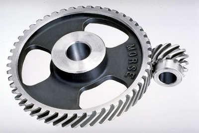
7 Helical Gear


8 Herringbone gears To avoid axial thrust, two helical gears of opposite hand can be mounted side by side, to cancel resulting thrust forces Herringbone gears are mostly used on heavy machinery.
 A perfect example of this is the steering system on many cars")
9 Rack and pinion Rack and pinion gears are used to convert rotation (From the pinion) into linear motion (of the rack) A perfect example of this is the steering system on many cars
10 Bevel gears Bevel gears are useful when the direction of a shaft's rotation needs to be changed They are usually mounted on shafts that are 90 degrees apart, but can be designed to work at other angles as well The teeth on bevel gears can be straight, spiral or hypoid locomotives, marine applications, automobiles, printing presses, cooling towers, power plants, steel plants, railway track inspection machines, etc.


11 Straight and Spiral Bevel Gears
12 WORM AND WORM GEAR Worm gears are used when large gear reductions are needed. It is common for worm gears to have reductions of 20:1, and even up to 300:1 or greater Many worm gears have an interesting property that no other gear set has: the worm can easily turn the gear, but the gear cannot turn the worm Worm gears are used widely in material handling and transportation machinery, machine tools, automobiles etc

13 WORM AND WORM GEAR
14 NOMENCLATURE OF SPUR GEARS
15 NOMENCLATURE. Pitch surface: The surface of the imaginary rolling cylinder (cone, etc.) that the toothed gear may be considered to replace. Pitch circle: A right section of the pitch surface. Addendum circle: A circle bounding the ends of the teeth, in a right section of the gear. Root (or dedendum) circle: The circle bounding the spaces between the teeth, in a right section of the gear. Addendum: The radial distance between the pitch circle and the addendum circle. Dedendum: The radial distance between the pitch circle and the root circle. Clearance: The difference between the dedendum of one gear and the addendum of the mating gear.
16 NOMENCLATURE. Face of a tooth: That part of the tooth surface lying outside the pitch surface. Flank of a tooth: The part of the tooth surface lying inside the pitch surface. Circular thickness (also called the tooth thickness): The thickness of the tooth measured on the pitch circle. It is the length of an arc and not the length of a straight line. Tooth space: pitch diameter The distance between adjacent teeth measured on the pitch circle. Backlash: The difference between the circle thickness of one gear and the tooth space of the mating gear. Circular pitch (Pc) : The width of a tooth and a space, measured on the pitch circle. D P c N
17 NOMENCLATURE. Diametral pitch (Pd): The number of teeth of a gear unit pitch diameter. The diametral pitch is, by definition, the number of teeth divided by the pitch diameter. That is, Where Pd = diametral pitch N = number of teeth D = pitch diameter P d N D Module (m): Pitch diameter divided by number of teeth. The pitch diameter is usually specified in inches or millimeters; in the former case the module is the inverse of diametral pitch. m = D/N
18 VELOCITY RATIO OF GEAR DRIVE d = Diameter of the wheel N =Speed of the wheel ω = Angular speed velocity ratio (n) = 2 1 N N 2 1 d d 1 2
19 GEAR TRAINS A gear train is two or more gear working together by meshing their teeth and turning each other in a system to generate power and speed It reduces speed and increases torque Electric motors are used with the gear systems to reduce the speed and increase the torque
20 Types of Gear Trains Simple gear train Compound gear train Planetary gear train Simple Gear Train The most common of the gear train is the gear pair connecting parallel shafts. The teeth of this type can be spur, helical or herringbone. Only one gear may rotate about a single axis
21 Simple Gear Train
22 Compound Gear Train For large velocities, compound arrangement is preferred Two or more gears may rotate about a single axis

")
23 Planetary Gear Train (Epicyclic Gear Train)
24 Planetary Gear Train In this train, the blue gear has six times the diameter of the yellow gear The size of the red gear is not important because it is just there to reverse the direction of rotation In this gear system, the yellow gear (the sun) engages all three red gears (the planets) simultaneously All three are attached to a plate (the planet carrier), and they engage the inside of the blue gear (the ring) instead of the outside.
25 Planetary Gear Train Because there are three red gears instead of one, this gear train is extremely rugged. planetary gear sets is that they can produce different gear ratios depending on which gear you use as the input, which gear you use as the output, and which one you hold still.
26 Planetary Gear Train They have higher gear ratios. They are popular for automatic transmissions in automobiles. They are also used in bicycles for controlling power of pedaling automatically or manually. They are also used for power train between internal combustion engine and an electric motor
Lecture (7) on. Gear Measurement. By Dr. Emad M. Saad. Industrial Engineering Dept. Faculty of Engineering. Fayoum University.
 on. Gear Measurement. By Dr. Emad M. Saad. Industrial Engineering Dept. Faculty of Engineering. Fayoum University.") 1 Lecture (7) on Gear Measurement Fayoum University By Dr. Emad M. Saad Industrial Engineering Dept. Faculty of Engineering Fayoum University Faculty of Engineering Industrial Engineering Dept. 2015-2016
1 Lecture (7) on Gear Measurement Fayoum University By Dr. Emad M. Saad Industrial Engineering Dept. Faculty of Engineering Fayoum University Faculty of Engineering Industrial Engineering Dept. 2015-2016
Part VII: Gear Systems: Analysis
 Part VII: Gear Systems: Analysis This section will review standard gear systems and will provide the basic tools to perform analysis on these systems. The areas covered in this section are: 1) Gears 101:
What are the functions of gears? What is gear?
 8//0 hapter seven Laith atarseh are very important in power transmission between a drive rotor and driven rotor What are the functions of gears? - Transmit motion and torque (power) between shafts - Maintain
(POWER TRANSMISSION Methods)
") UNIT-5 (POWER TRANSMISSION Methods) It is a method by which you can transfer cyclic motion from one place to another or one pulley to another pulley. The ways by which we can transfer cyclic motion are:-
UNIT-5 (POWER TRANSMISSION Methods) It is a method by which you can transfer cyclic motion from one place to another or one pulley to another pulley. The ways by which we can transfer cyclic motion are:-
Chapter seven. Gears. Laith Batarseh
 Chapter seven Gears Laith Batarseh Gears are very important in power transmission between a drive rotor and driven rotor What are the functions of gears? - Transmit motion and torque (power) between shafts
CH#13 Gears-General. Drive and Driven Gears 3/13/2018
 CH#13 Gears-General A toothed wheel that engages another toothed mechanism in order to change the speed or direction of transmitted motion The gear set transmits rotary motion and force. Gears are used
12/6/2013 9:09 PM. Chapter 13. Gears General. Dr. Mohammad Suliman Abuhaiba, PE
 Chapter 13 Gears General 1 2 Chapter Outline 1. Types of Gears 2. Nomenclature 3. Conjugate Action 4. Involute Properties 5. Fundamentals 6. Contact Ratio 7. Interference 8. The Forming of Gear Teeth 9.
1/2/2015 2:04 PM. Chapter 13. Gears General. Dr. Mohammad Suliman Abuhaiba, PE
 Chapter 13 Gears General 1 2 Chapter Outline 1. Types of Gears 2. Nomenclature 3. Conjugate Action 4. Involute Properties 5. Fundamentals 6. Contact Ratio 7. Interference 8. The Forming of Gear Teeth 9.
Introduction. Kinematics and Dynamics of Machines. Involute profile. 7. Gears
 Introduction The kinematic function of gears is to transfer rotational motion from one shaft to another Kinematics and Dynamics of Machines 7. Gears Since these shafts may be parallel, perpendicular, or
Different types of gears. Spur gears. Idler gears. Worm gears. Bevel gears. Belts & Pulleys
 GEARS Robot Gears By using different gear diameters, you can exchange between rotational (or translation) velocity and torque. by looking at the motor datasheet you can determine the output velocity and
Catalog Q Conversion For those wishing to ease themselves into working with metric gears
 1.3.4 Conversion For those wishing to ease themselves into working with metric gears by looking at them in terms of familiar inch gearing relationships and mathematics, Table 1-5 is offered as a means
11/23/2013. Chapter 13. Gear Trains. Dr. Mohammad Suliman Abuhiba, PE
 Chapter 13 Gear Trains 1 2 13.2. Types of Gear Trains 1. Simple gear train 2. Compound gear train 3. Reverted gear train 4. Epicyclic gear train: axes of shafts on which the gears are mounted may move
11. GEAR TRANSMISSIONS
 11. GEAR TRANSMISSIONS 11.1. GENERAL CONSIDERATIONS Gears are one of the most important elements used in machinery. There are few mechanical devices that do not have the need to transmit power and motion
Gear Tooth Geometry - This is determined primarily by pitch, depth and pressure angle
 Gear Tooth Geometry - This is determined primarily by pitch, depth and pressure angle Addendum: The radial distance between the top land and the pitch circle. Addendum Circle: The circle defining the outer
Chapter 8 Kinematics of Gears
 Chapter 8 Kinematics of Gears Gears! Gears are most often used in transmissions to convert an electric motor s high speed and low torque to a shaft s requirements for low speed high torque: Speed is easy
Basic Fundamentals of Gear Drives
 Basic Fundamentals of Gear Drives Course No: M06-031 Credit: 6 PDH A. Bhatia Continuing Education and Development, Inc. 9 Greyridge Farm Court Stony Point, NY 10980 P: (877) 322-5800 F: (877) 322-4774
Instantaneous Centre Method
 Instantaneous Centre Method The combined motion of rotation and translation of the link AB may be assumed to be a motion of pure rotation about some centre I, known as the instantaneous centre of rotation.
Chapter 3. Transmission Components
 Chapter 3. Transmission Components The difference between machine design and structure design An important design problem in a mechanical system is how to transmit and convert power to achieve required
Metrology Prof. Dr Kanakuppi Sadashivappa Bapuji Institute of Engineering and Technology Davangere. Lecture 25 Introduction of Gears
 Metrology Prof. Dr Kanakuppi Sadashivappa Bapuji Institute of Engineering and Technology Davangere Lecture 25 Introduction of Gears I welcome you for the series of lecture on gear measurement and at module
Copyright Notice. Small Motor, Gearmotor and Control Handbook Copyright Bodine Electric Company. All rights reserved.
 Copyright Notice Small Motor, Gearmotor and Control Handbook Copyright 1993-2003 Bodine Electric Company. All rights reserved. Unauthorized duplication, distribution, or modification of this publication,
UNIT -I. Ans: They are specified by the no. of strands & the no. of wires in each strand.
 VETRI VINAYAHA COLLEGE OF ENGINEERING AND TECHNOLOGY, THOTTIAM, NAMAKKAL-621215. DEPARTMENT OF MECHANICAL ENGINEERING SIXTH SEMESTER / III YEAR ME6601 DESIGN OF TRANSMISSION SYSTEM (Regulation-2013) UNIT
Unit IV GEARS. Gallery
 Gallery Components of a typical, four stroke cycle, DOHC piston engine. (E) Exhaust camshaft, (I) Intake camshaft, (S) Spark plug, (V) Valves, (P) Piston, (R) Connecting rod, (C) Crankshaft, (W) Water
ME6601 DESIGN OF TRANSMISSION SYSTEMS
 SYED AMMAL ENGINEERING COLLEGE (Approved by the AICTE, New Delhi, Govt. of Tamilnadu and Affiliated to Anna University, Chennai) Established in 1998 - An ISO 9001:2008 Certified Institution Dr. E.M.Abdullah
TECHNOLOGY MECHANISMS
 TECHNOLOGY MECHANISMS 3º ESO IES CHAN DO MONTE URTAZA 1 WHAT IS A MECHANISM? Mechanism are devices that have been designed to make jobs easier. They all have certain things in common: They involve some
Spur Gears. Helical Gears. Bevel Gears. Worm Gears
 Spur s General: Spur gears are the most commonly used gear type. They are characterized by teeth which are perpendicular to the face of the gear. Spur gears are by far the most commonly available, and
SECTION 8 BEVEL GEARING
 SECTION 8 BEVEL GEARING For intersecting shafts, bevel gears offer a good means of transmitting motion and power. Most transmissions occur at right angles, Figure 8-1, but the shaft angle can be any value.
Gear Engineering Data. Spur Gear Gear Formulas Drive Selection Horsepower and Torque Tables
 Engineering Gear Engineering Data Spur Gear Gear Formulas Drive Selection Horsepower and Torque Tables G-79 Gear Selection Stock Spur Gear Drive Selection When designing a stock gear drive using the horsepower
Gear Drives. A third gear added to the system will rotate in the same direction as the drive gear Equal diameters = Equal number of teeth = Same speed
 Gear Drive Systems Gear Drives Gear Drive: Synchronous mechanical drive that uses gears to transfer power Gear: A toothed wheel that meshes with other toothed wheels to transfer rotational power Pinion
1.6 Features of common gears
 1.6 Features of common gears Chapter 1.2 covered briefly on types of gear. The main gear features are explained here. Helical gear Helical gear has characteristics of transferability of larger load, less
CHAPTER 6 GEARS CHAPTER LEARNING OBJECTIVES
 CHAPTER 6 GEARS CHAPTER LEARNING OBJECTIVES Upon completion of this chapter, you should be able to do the following: Compare the types of gears and their advantages. Did you ever take a clock apart to
Mechanism Feasibility Design Task
 Mechanism Feasibility Design Task Dr. James Gopsill 1 Contents 1. Last Week 2. Types of Gear 3. Gear Definitions 4. Gear Forces 5. Multi-Stage Gearbox Example 6. Gearbox Design Report Section 7. This Weeks
Graphical representation of a gear
 Homework 4 Gears Gears are designed to transmit rotary motion. Often they are arranged in a gear train (meshed together). Gear trains provide a change in speed, torque (turning force) and direction (clockwise
Bevel Gears. Fig.(1) Bevel gears
 Bevel gears") Bevel Gears Bevel gears are cut on conical blanks to be used to transmit motion between intersecting shafts. The simplest bevel gear type is the straighttooth bevel gear or straight bevel gear as can be
Bevel Gears Bevel gears are cut on conical blanks to be used to transmit motion between intersecting shafts. The simplest bevel gear type is the straighttooth bevel gear or straight bevel gear as can be
St.MARTIN S ENGINEERING COLLEGE Dhulapally, Secunderabad
 St.MARTIN S ENGINEERING COLLEGE Dhulapally, Secunderabad-500 014 Subject: Kinematics of Machines Class : MECH-II Group A (Short Answer Questions) UNIT-I 1 Define link, kinematic pair. 2 Define mechanism
ME6401 KINEMATICS OF MACHINERY UNIT- I (Basics of Mechanism)
") ME6401 KINEMATICS OF MACHINERY UNIT- I (Basics of Mechanism) 1) Define resistant body. 2) Define Link or Element 3) Differentiate Machine and Structure 4) Define Kinematic Pair. 5) Define Kinematic Chain.
ME6401 KINEMATICS OF MACHINERY UNIT- I (Basics of Mechanism) 1) Define resistant body. 2) Define Link or Element 3) Differentiate Machine and Structure 4) Define Kinematic Pair. 5) Define Kinematic Chain.
1. (a) Discuss various types of Kinematic links with examples. (b) Explain different types of constrained motions with examples.
 Discuss various types of Kinematic links with examples. (b) Explain different types of constrained motions with examples.") Code No: RR310304 Set No. 1 III B.Tech I Semester Supplementary Examinations, February 2007 KINEMATICS OF MACHINERY ( Common to Mechanical Engineering, Mechatronics and Production Engineering) Time: 3
Code No: RR310304 Set No. 1 III B.Tech I Semester Supplementary Examinations, February 2007 KINEMATICS OF MACHINERY ( Common to Mechanical Engineering, Mechatronics and Production Engineering) Time: 3
KINGS COLLEGE OF ENGINEERING DEPARTMENT OF MECHANICAL ENGINEERING
 KINGS COLLEGE OF ENGINEERING DEPARTMENT OF MECHANICAL ENGINEERING QUESTION BANK Sub Code/Name: ME 1352 DESIGN OF TRANSMISSION SYSTEMS Year/Sem: III / VI UNIT-I (Design of transmission systems for flexible
MANUFACTURING OF GEAR BOXES
 Profile No.: 29 NIC Code: 29301 MANUFACTURING OF GEAR BOXES 1. INTRODUCTION: Gears play a prominent role in mechanical power transmission. A gear or cogwheel is a rotating machine part having cut teeth,
GEARING. Theory of. Stephen. Kinetics, Geometry, and Synthesis. P. Radzevich. /Ov CRC Press yc*** J Taylor& Francis Croup Boca Raton
 Theory of GEARING Kinetics, Geometry, and Synthesis Stephen P. Radzevich /Ov CRC Press yc*** J Taylor& Francis Croup Boca Raton London New York CRC Press is an imprint of the Taylor & Francis Group, an
BRCM COLLEGE OF ENGINEERING & TECHNOLOGY BAHAL, BHIWANI Practical Experiment Instructions Sheet
 BRCM COLLEGE OF KOM ME- 212 F KINEMATICS OF MACHINES LAB BRANCH-ME List of Experiments : 1. To study various types of Kinematic links, pairs, chains and Mechanisms. 2. To study inversions of 4 Bar Mechanisms,
MECHANICAL DRIVES 1 SPUR GEAR DRIVES LEARNING ACTIVITY PACKET BB502-XD06AEN
 MECHANICAL DRIVES 1 LEARNING ACTIVITY PACKET SPUR GEAR DRIVES BB502-XD06AEN LEARNING ACTIVITY PACKET 6 SPUR GEAR DRIVES INTRODUCTION This LAP will begin the study of the third type of adjacent shaft-to-shaft
Introduction to Gear Design
 Introduction to Gear Design Course No: M03-016 Credit: 3 PDH Robert P. Tata, P.E. Continuing Education and Development, Inc. 9 Greyridge Farm Court Stony Point, NY 10980 P: (877) 322-5800 F: (877) 322-4774
 DEPARTMENT OF MECHANICAL ENGINEERING Subject code: ME6601 Subject Name: DESIGN OF TRANSMISSION SYSTEMS UNIT-I DESIGN OF TRANSMISSION SYSTEMS FOR FLEXIBLE ELEMENTS 1. What is the effect of centre distance
Gear Measurement. Lecture (7) Mechanical Measurements
 Mechanical Measurements") 18 3. Gear profile checking 2. Involute measuring machine In this method the gear is held on a mandrel and circular disc of same diameter as the base circle of gear for the measurement is fixed on the
18 3. Gear profile checking 2. Involute measuring machine In this method the gear is held on a mandrel and circular disc of same diameter as the base circle of gear for the measurement is fixed on the
Sheet 1 Variable loading
 Sheet 1 Variable loading 1. Estimate S e for the following materials: a. AISI 1020 CD steel. b. AISI 1080 HR steel. c. 2024 T3 aluminum. d. AISI 4340 steel heat-treated to a tensile strength of 1700 MPa.
BEVELGEAR. Competence and Performance.
 BEVELGEAR Competence and Performance www.graessner.de General Advantages of Spiral, Hypoid and Zerol Bevel Gears High level of coverage due to the fact that several teeth are meshed simultaneously Resistant
Bevel Gears n A Textbook of Machine Design
 080 n A Textbook of Machine Design C H A P T E R 30 Bevel Gears. Introduction.. Classification of Bevel Gears. 3. Terms used in Bevel Gears. 4. Determination of Pitch Angle for Bevel Gears. 5. Proportions
KINEMATICS OF MACHINARY UBMC302 QUESTION BANK UNIT-I BASICS OF MECHANISMS PART-A
 KINEMATICS OF MACHINARY UBMC302 QUESTION BANK UNIT-I BASICS OF MECHANISMS PART-A 1. Define the term Kinematic link. 2. Classify kinematic links. 3. What is Mechanism? 4. Define the terms Kinematic pair.
GEARBOXES. Gearboxes. Gearboxes. Gearbox is a mechanical device utilized to increase the output torque or change
 GEARBOXES Gearboxes Gearboxes Gearbox is a mechanical device utilized to increase the output torque or change the speed of a motor. The motor's shaft is attached to one end of the gearbox and through the
T25 T25 T25 T27 T27 T28 T28 T28 T28 T29 T29 T29 T31 T37 T37 T38 T T T48
 1.0 INTRODUCTION 2.0 BASIC GEOMETRY OF SPUR GEARS 2.1 Basic Spur Gear Geometry 2.2 The Law of Gearing 2.3 The Involute Curve 2.4 Pitch Circles 2.5 Pitch 2.5.1 Circular Pitch 2.5.2 Diametral Pitch 2.5.3
we will learn how to conduct force and torque analysis on gears in order to calculate bearing
 8.1 Introduction to Gears Gears are used to transmit motion and torque from one shaft to another. In this section we will discuss the kinematics of gears; that is, the motion relationships between gears.
Chain Drives. Pitch. Basic Types -There are six major types of power-
 1 2 Power transmission chains have two things in common; side bars or link plates, and pin and bushing joints. The chain articulates at each joint to operate around a toothed sprocket. The pitch of the
What is a Mechanism?
 Mechanisms What is a Mechanism? A mechanism is the part of a machine which contains two or more pieces arranged so that the motion of one compels the motion of the others. Generally used to: Change the
Session #3 Gears: Force Transmission & Gear Trains. Dan Frey
 Session #3 Gears: Force Transmission & Gear Trains Dan Frey Today s Agenda Pass out second reading packet Pass out loaner laptops Introduce project teams Gears Force Transmission Gear Trains Survey HW
1.7 Backlash. Summary of the backlash is play or clearance between one pair of gear. Fig. 17 Backlash
 1.7 Backlash Summary of the backlash is play or clearance between one pair of gear. Fig. 17 Backlash Great care is taken to produce the gear with zero deviation. However we are unable to completely eliminate
Engineering Information
 Engineering nformation Gear Nomenclature ADDENDUM (a) is the height by which a tooth projects beyond the pitch circle or pitch line. BASE DAMETER (D b ) is the diameter of the base cylinder from which
Mechanisms. Prepared by Juan Blázquez, Alissa Gildemann
 Unit 9 Mechanisms 1. Mechanisms Mechanisms are devices that transmit and convert forces and motions from an input to an output element. They enable us to use less effort to carry out a task. We can classify
UNIT III TRANSMISSION SYSTEMS CONTENTS: Clutch-types and construction Gear boxes- manual and automatic Gear shift mechanisms Over drive Transfer box
 UNIT III TRANSMISSION SYSTEMS CONTENTS: Clutch-types and construction Gear boxes- manual and automatic Gear shift mechanisms Over drive Transfer box Fluid flywheel Torque converter Propeller shaft Slip
2. a) What is pantograph? What are its uses? b) Prove that the peaucellier mechanism generates a straight-line motion. (5M+10M)
 What is pantograph? What are its uses? b) Prove that the peaucellier mechanism generates a straight-line motion. (5M+10M)") Code No: R22032 R10 SET - 1 1. a) Define the following terms? i) Link ii) Kinematic pair iii) Degrees of freedom b) What are the inversions of double slider crank chain? Describe any two with neat sketches.
Code No: R22032 R10 SET - 1 1. a) Define the following terms? i) Link ii) Kinematic pair iii) Degrees of freedom b) What are the inversions of double slider crank chain? Describe any two with neat sketches.
MECH 1200 Quiz 2 Review
 Name: Class: Date: MECH 1200 Quiz 2 Review True/False Indicate whether the statement is true or false. 1. Gears are machined toothed wheels that engage other toothed wheels to transfer power and torque.
Code No: R Set No. 1
 Code No: R05310304 Set No. 1 III B.Tech I Semester Regular Examinations, November 2007 KINEMATICS OF MACHINERY ( Common to Mechanical Engineering, Mechatronics, Production Engineering and Automobile Engineering)
Technology of Machine Tools
 PowerPoint to accompany Technology of Machine Tools 6 th Edition Krar Gill Smid Gear Cutting Unit 70 Copyright The McGraw-Hill Companies, Inc. Permission required for reproduction or display. 70-2 Objectives
Marine Engineering Exam Resource Review of Couplings
 1. What are rigid couplings used for? Used to join drive shafts together. True alignment and rigidity are required. Example Drive shafts and production lines, bridge cranes, solid shaft that needs to be
Lecture 13 BEVEL GEARS
 Lecture 13 BEVEL GEARS CONTENTS 1. Bevel gear geometry and terminology 2. Bevel gear force analysis 3. Bending stress analysis 4. Contact stress analysis 5. Permissible bending fatigue stress 6. Permissible
General gear terms and definitions. Trantorque 48 DP. Steel and Brass
 General gear terms and definitions 317 Spur and Helical Gears: Formulae and definitions Helical Gear Spur Gear Term Definition formulae formulae 318 Spur and Helical Gears: Formulae and definitions Helical
428 l Theory of Machines
 428 l heory of Machines 13 Fea eatur tures es 1. Introduction. 2. ypes of Gear rains. 3. Simple Gear rain. 4. ompound Gear rain. 5. Design of Spur Gears. 6. Reverted Gear rain. 7. picyclic Gear rain. 8.
Design of Helical Gear and Analysis on Gear Tooth
 Design of Helical Gear and Analysis on Gear Tooth Indrale Ratnadeep Ramesh Rao M.Tech Student ABSTRACT Gears are mainly used to transmit the power in mechanical power transmission systems. These gears
SECTION 4 SPUR GEAR CALCULATIONS
 Function of α, or invα, is known as involute function. Involute function is very important in gear design. Involute function values can be obtained from appropriate tables. With the 3.1 Contact Ratio center
Available in July 2010
 Available in July 2010 SGFD/SGFK/SGCPFD Ground acks m0.5~ 18 items engths : 0, 0 and 1000mm CP5~20 8 items engths : 0 and 1000mm The product line-up for the popular J-Series has expanded! Quick-touse Ground
'' ''' '' ''' Code No: R R16 SET - 1
 Code No: R161232 R16 SET - 1 1. a) List the Primary requirements of a Steam Boiler. (2M) b) What are the distinguishing features between a Casting and a Pattern? (2M) c) Define (i) Brake Power; (ii) Indicated
Effect of Geometry Factor I & J Factor Multipliers in the performance of Helical Gears
 Effect of Geometry Factor I & J Factor Multipliers in the performance of Helical Gears 1 Amit D. Modi, 2 Manan B. Raval, 1 Lecturer, 2 Lecturer, 1 Department of Mechanical Engineering, 2 Department of
CHENDU COLLEGE OF ENGINEERING & TECHNOLOGY DEPARTMENT OF MECHANICAL ENGINEERING QUESTION BANK IV SEMESTER
 CHENDU COLLEGE OF ENGINEERING & TECHNOLOGY DEPARTMENT OF MECHANICAL ENGINEERING QUESTION BANK IV SEMESTER Sub Code: ME 6401 KINEMATICS OF MACHINERY UNIT-I PART-A 1. Sketch and define Transmission angle
Gearheads H-51. Gearheads for AC Motors H-51
 Technical Reference H-51 for AC Since AC motor gearheads are used continuously, primarily for transmitting power, they are designed with priority on ensuring high permissible torque, long life, noise reduction
UNIT -1 TRANSMISSION SYSTEMS USING FLEXIBLE ELEMENTS. 1. What are the factors controlling selection of a transmission drive?
 UNIT -1 TRANSMISSION SYSTEMS USING FLEXIBLE ELEMENTS 1. What are the factors controlling selection of a transmission drive? The factors are, a) Amount of power to be transmitted b) Velocity ratio c) Service
ISO INTERNATIONAL STANDARD. Bevel and hypoid gear geometry. Géométrie des engrenages coniques et hypoïdes. First edition
 INTERNATIONAL STANDARD ISO 23509 First edition 2006-09-01 Bevel and hypoid gear geometry Géométrie des engrenages coniques et hypoïdes Reference number ISO 2006 Provläsningsexemplar / Preview PDF disclaimer
Mechanotechnology N3 Lecturer s Guide
 Mechanotechnology N3 Lecturer s Guide ISBN: 978-1-4308-0617-2 R Cameron & LL Maraschin This Lecturer s Guide accompanies the following Student s Book: Title: Mechanotechnology N3 Author: R Cameron & LL
Chapter 10 Machine elements. Bachelor Program in AUTOMATION ENGINEERING Prof. Rong-yong Zhao Second Semester,
 Chapter 10 Machine elements Bachelor Program in AUTOMATION ENGINEERING Prof. Rong-yong Zhao (zhaorongyong@tongji.edu.cn) Second Semester,2013-2014 Content 10.1 Cams 10.1.1- Synthesis of the mechanism 10.1.2-
SYED AMMAL ENGINEERING COLLEGE
 SYED AMMAL ENGINEERING COLLEGE (Approved by the AICTE, New Delhi, Govt. of Tamilnadu and Affiliated to Anna University, Chennai) Established in 1998 - An ISO 9001:2000 Certified Institution Dr. E.M.Abdullah
The Geometry of Involute Gears
 The Geometry of Involute Gears J.R. Colbourne The Geometry of Involute Gears With 217 Illustrations Springer-Verlag New York Berlin Heidelberg London Paris Tokyo J.R. Colbourne Department of Mechanical
Internal Gears. No. of teeth (60) Module (1) Others (Ring Gear) Type (Internal Gear) Material (S45C)
 Module (1) Others (Ring Gear) Type (Internal Gear) Material (S45C)") ph: (410)8-10 (0)68-180 fx: (410)8-142 (0)872-929 rfq form: http://mdmetric.com/rfq.htm Internal Internal Miter CP Racks & Pinions Racks Helical Spur SI Steel Internal SIR Steel Ring m0. ~ Page 184 m2
ph: (410)8-10 (0)68-180 fx: (410)8-142 (0)872-929 rfq form: http://mdmetric.com/rfq.htm Internal Internal Miter CP Racks & Pinions Racks Helical Spur SI Steel Internal SIR Steel Ring m0. ~ Page 184 m2
50 g 50 e g ars e o ars lut o i lut on o s n.c s o.c m o
 50 gearsolutions.com Analysis and Optimization of Asymmetric Epicyclic Gears By Alexander L. Kapelevich Following the Direct Gear Design approach to asymmetric epicyclic gear stages with singular and compound
 DEPARTMENT OF MECHANICAL ENGINEERING ME6401- KINEMATICS OF MACHINERY QUESTION BANK Part-A Unit 1-BASICS OF MECHANISMS 1. Define degrees of freedom. 2. What is meant by spatial mechanism? 3. Classify the
Mechanics and Mechanisms. What is do you think about when you hear the word mechanics? Mechanics. Is this a mechanism? 2/17/2011
 Mechanics and Mechanisms What is do you think about when you hear the word mechanics? Mechanics Mechanics is the study of how things move Is this a mechanism? Concerned with creating useful movement through
INVOLUTE SPIRAL FACE COUPLINGS AND GEARS: DESIGN APPROACH AND MANUFACTURING TECHNIQUE
 УДК 621.9.015 Dr. Alexander L. Kapelevich, Stephen D. Korosec 38 INVOLUTE SPIRAL FACE COUPLINGS AND GEARS: DESIGN APPROACH AND MANUFACTURING TECHNIQUE This paper presents spiral face gears with an involute
Tooth thickness Dedendum. Addendum. Centre distance Nominal
 FORMULAS SPUR GEARS TO FIND:- PCD ØD MODULE No. of TEETH CP ADDENDUM DEDENDUM MODULE No. of TEETH x MOD (mm) (No. of TEETH + ) x MOD (mm) 5.4 MODULE CP π (mm) PCD MODULE (mm) MODULE x π (mm) MODULE (mm)
BEVELGEAR. Competence and Performance.
 MS-Graessner GmbH & Co. KG THE GEAR COMPANY BEVELGEAR Competence and Performance General Advantages of Spiral, Hypoid and Zerol Bevel Gears High level of coverage due to the fact that several teeth are
Bibliography. [1] Buckingham, Earle: "Analytical Mechanics of Gears", McGraw-Hill, New York, 1949, and republished by Dover, New York, 1963.
![Bibliography. [1] Buckingham, Earle: Analytical Mechanics of Gears, McGraw-Hill, New York, 1949, and republished by Dover, New York, 1963.](/thumbs/87/96820687.jpg "Bibliography. [1] Buckingham, Earle: Analytical Mechanics of Gears, McGraw-Hill, New York, 1949, and republished by Dover, New York, 1963.") Bibliography The first five references listed are books on gearing. Some of them deal not only with the geometry, but also with many other aspects of gearing. However, the books are included in this bibliography
Bibliography The first five references listed are books on gearing. Some of them deal not only with the geometry, but also with many other aspects of gearing. However, the books are included in this bibliography
Machines and mechanisms
 Machines and mechanisms Contents: 1. Basics and Kinematics of Mechanism 2. Cam and Follower 3. Governor 4. Gear and Gear Train 5. Inertia Force Analysis Basics and Kinematics Mechanism: 1. A rigid body
Moments. It doesn t fall because of the presence of a counter balance weight on the right-hand side. The boom is therefore balanced.
 Moments The crane in the image below looks unstable, as though it should topple over. There appears to be too much of the boom on the left-hand side of the tower. It doesn t fall because of the presence
PRODUCT OVERVIEW HIGHEST PRECISION
 PRODUCT OVERVIEW If you need high precision gear reducers at a reasonable cost and you value innovation and excellent service, take a close look at our product line. You ll find a wide range of products
DHANALAKSHMI COLLEGE OF ENGINEERING
 DHANALAKSHMI COLLEGE OF ENGINEERING VISION Dhanalakshmi College of Engineering is committed to provide highly disciplined, conscientious and enterprising professionals conforming to global standards through
All levers are one of three types, usually called classes. The class of a lever depends on the relative position of the load, effort and fulcrum:
 Página 66 de 232 Mechanisms A mechanism is simply a device which takes an input motion and force, and outputs a different motion and force. The point of a mechanism is to make the job easier to do. The
Program Internal Gear Set Profile Shift Coefficients With Zero Backlash Introduction
 Program 60-107 Internal Gear Set Profile Shift Coefficients With Zero Backlash Introduction The purpose of this model is to provide data for a gear set when the tooth thickness and/or the center distance
IIJIID~(i1lJ INSTRUCTION MANUAL ~~ [~ ~ ~.1. [~ Gear Trains Apparatus HTM.25
 IIJIID~(i1lJ ~~ [~ ~ ~.1. [~ INSTRUCTION MANUAL HTM.25 Gear Trains Apparatus Gear Trains INTRODUCTION There are two main purposes for using a train of gears. The most important is to establish a speed
Design and Analysis of Six Speed Gear Box
 Design and Analysis of Six Speed Gear Box Ujjayan Majumdar 1, Sujit Maity 2, Gora Chand Chell 3 1,2 Student, Department of Mechanical Engineering, Jalpaiguri Government Engineering College, Jalpaiguri,
Stress Analysis of Spur Gear by using Different Materials: A Review
 Stress Analysis of Spur Gear by using Different Materials: A Review Ms. Nilesha U. Patil 1*, Mr. Sunil P. Chaphalkar 2,Mr. Gajanan L. Chaudhari 3 1 ME Student, Department of Mechanical Engineering, APCOER,
Martin Sprocket & Gear, Inc.
 GEAR MANUAL Published by Martin Sprocket & Gear, Inc. Dave Walton, Technical Advisor TABLE OF CONTENTS Introduction.....................................1 Work.......................................2 Power......................................2
KISSsys 03/2015 Instruction 010
 KISSsys 03/2015 Instruction 010 Positioning 07/04/2015 KISSsoft AG Rosengartenstrasse 4 8608 Bubikon Switzerland Tel: +41 55 254 20 50 Fax: +41 55 254 20 51 info@kisssoft.ag www.kisssoft.ag Contents 1.
Metric Standards Worldwide Japanese Metric Standards In This Text
 ELEMENTS OF METRIC GEAR TECHNOLOGY Table of Contents Page SECTION 1 INTRODUCTION TO METRIC GEARS 329 1.1 Comparison Of Metric Gears With American Inch Gears 329 1.1.1 1.1.2 1.1.3 Comparison of Basic Racks
Design and Fabrication of Shaft Drive for two Wheelers
 International OPEN ACCESS Journal Of Modern Engineering Research (IJMER) Design and Fabrication of Shaft Drive for two Wheelers K.Vinoth Kumar 1, Kari Naga Nikhil, Kakollu Manoj Kumar, Kaza Sai Sravan