50 g 50 e g ars e o ars lut o i lut on o s n.c s o.c m o
|
|
|
- Beatrix Parsons
- 5 years ago
- Views:
Transcription
1 50 gearsolutions.com


2 Analysis and Optimization of Asymmetric Epicyclic Gears By Alexander L. Kapelevich Following the Direct Gear Design approach to asymmetric epicyclic gear stages with singular and compound planet gears, methods of optimization of the tooth flank asymmetry factor and root fillet profile are considered. THE DESIGN OBJECTIVE OF ASYMMETRIC TOOTH gears is to improve performance of the primary drive flank profiles at the expense of the opposite coast profiles performance. The coast flanks are unloaded or lightly loaded during a relatively short work period. Such gears should be used for unidirectional or mostly unidirectional load transmission when the coast flanks are unloaded or lightly loaded during relatively short work time. In a simple epicycling gear stage, the singular planet gear transmits the same load by both tooth flanks. However, the convex planet gear tooth flanks are in simultaneous meshes with the convex sun gear tooth flanks and the concave ring gear tooth flanks resulting in very different contact stress values in those meshes. In epicycling gear drives with compound planet gears, one portion of the planet gear is in mesh with the sun gear and other one with the ring gear. In this case, the coast tooth flanks are used only when the gear drive works in a reversed load direction. This paper describes a gear geometry analysis and the asymmetry factor and tooth root fillet optimization of epicycling stages with singular and compound planet gears. This allows for a considerable increase in power transmission density, increase in load capacity, and reduction in the size and weight of asymmetric epicyclic gear drives. BASIC ASYMMETRIC EPICYCLIC GEAR STAGES Epicyclic gear stages provide high load capacity and compactness to gear drives. There is a huge variety of different combinations of planetary gear arrangements. Although some of them are quite complicated, they typically contain simple epicyclic stages with singular planet gears (see Figure 1) or epicyclic stages with compound planet gears (see Figure 2). For an epicyclic planetary stage with singular planet gears where the ring gear is stationary, the practical gear ratio varies from 3:1 to 9:1; for an epicyclic planetary stage with compound planet gears, the practical gear ratio varies from 8:1 to 30:1 [1]. Figure 1: Epicyclic stage with singular planet gears; numbers of teeth: z 1 sun gear, z 2 planet gear, and z 3 ring gear Figure 2: Epicyclic stage with compound planet gears; numbers of teeth: z 1, sun gear, z 2 planet gear portion engaged with sun gear, z 2 planet gear portion engaged with ring gear, and z 3 ring gear The gear ratio of an epicyclic gear stage depends on its arrangement. The most common arrangements are the solar stage with the stationary carrier, the planetary stage with the stationary ring gear, and the differential stage where the carrier and ring gear are rotating with the same rpm but in opposite directions. Table 1 presents the gear ratio equations for different epicyclic arrangements. ASYMMETRY FACTOR OPTIMIZATION Epicyclic Stage with Singular Planet Gears In an epicyclic stage with singular planet gears (see Figure 3), opposite flanks of the planet gear are in simultaneous contact with the sun and ring gears. In this case, the goal Table 1 AUGUST
3 service life or the safety factor in the limited life stress range is determined using life factor Z NT. This allows replacing the permissible contact stresses in Equation 18 with life factors: Equation 6 where z NT12 and z NT23 are the life factors in the sun/planet and planet/ ring gear meshes respectively. These life factors can be defined by numbers of load cycles. The load cycle number ratio in an epicyclic stage with singular planet gears is: Figure 3: Epicyclic mesh with singular planet gears of asymmetry factor optimization is equalization of the contact stress safety factors in the external mesh of the sun and planet gears and the internal mesh of the planet and ring gears. The flank contact stress safety factor is: Equation 1 where σ HP12 and σ HP23 are permissible contact stress in the sun/ planet gear mesh and the planet/ring gear mesh, and σ H12 and σ H23 are maximum operating contact stress in the sun/planet gear mesh and the planet/ring gear mesh. Equation 1 can be converted into the operating contact stress ratio: Equation 2 In order to simplify the asymmetry factor optimization, the maximum contact stresses in the sun/planet and planet/ring gear meshes are replaced with the contact stress at the pitch points. The operating contact stresses at the pitch points (in the sun/planet gear mesh) are: Equation 3 where Z E elastic factor (material property factors), u 12 = z 2 /z 1 sun/planet mesh gear ratio, b w12 contact face width, α wd12 drive flank pressure angle, T d1 sun gear driving torque (in the sun/ planet gear mesh): Equation 7 where N 12 and N 23 are the numbers of load cycles in the sun/planet and planet/ring gear meshes respectively. Then, the asymmetry factor [3] is: Equation 8 For example: The sun gear number of teeth is n 1 = 37, the planet gear number of teeth is n 2 = 32, the output gear number of teeth is n 3 = 101, the contact face width ratio is b w12 /b w23 = 1.4, the number of load cycles in the sun/planet gear mesh is n 12 = 10 9, the number of load cycles in the planet/ring gear mesh is n 23 = n 12 x z 1 /z 3 = 3.7 x This makes the life factors for nitrocarburized steel Z NT12 = 0.89 and Z NT23 = 0.90, and the factor A = If the selected sun/ planet gear mesh drive pressure angle α wd12 = 36, the asymmetry coefficient is K = 1.16 and the planet/ring gear mesh drive pressure angle is α wd23 = Epicyclic Stage with Compound Planet Gears In an epicyclic stage with compound planet gears (see Figure 2), one portion of the planet gear is in mesh with the sun gear and the other with the ring gear. In this case, the coast tooth flanks are used only when the gear drive works in a reversed load direction. The goal of asymmetry factor optimization is equalization of the contact stress safety factors in the main drive and opposite reversed load transmission directions. Equation 4 where u 23 = z 3 /z 2 planet/ring mesh gear ratio, b w23 contact face width, α wd23 drive flank pressure angle. Assuming all gears are made from the same material and inserting Equations 3 and 4 into Equation 2, the coefficient A is equal to: Equation 5 According to Reference [2], The permissible stress at limited Figure 4: Epicyclic mesh with compound planet gears 52 gearsolutions.com

4 Then, the flank contact stress safety factor is: Equation 9 where σ HPd and σ HPc are permissible contact stress in the main drive and opposite reversed load transmission directions, and σ Hd and σ Hc are maximum operating contact stress in the main drive and opposite reversed load transmission directions. Equation 9 can be converted into the operating contact stress ratio: Equation 10 In order to simplify the asymmetry factor optimization, maximum contact stresses are replaced with the contact stress at the pitch points. The operating contact stresses at the pitch points (in the main drive load transmission direction) are: Equation 11 Equation 12 where u 12 = z 2 /z 1 sun/planet mesh gear ratio, u 2 3 = z 3 /z 2 planet/ring mesh gear ratio, z 2 tooth numbers of the planet gear engaged with the sun gear, z 2 tooth numbers of the planet gear engaged with the ring gear, b w12 and b w2 3 contact face widths in the sun/planet gear mesh and the planet/ring gear mesh, α wd12 and α wd2 3 drive flank pressure angles in the sun/planet and the planet/ring gear meshes respectively, and T d1 sun gear driving torque (in the main drive load transmission direction): where Z NTd and Z NTc are the life factors in the main drive and opposite reversed load transmission directions respectively, which are defined by N d and N c the numbers of load cycles in the main drive and opposite reversed load transmission directions. Then, the asymmetry factors (in the sun/planet gear mesh) are: and (in the planet/ring gear mesh): Equation 17 Equation 18 Unlike in the epicyclic asymmetric gear stage with singular planet gears, the optimized asymmetry coefficients depend only on the main driving and reversed torque ratio and numbers of cycles in the main drive and reversed load transmission directions. For example: Main driving and reversed torque ratio is T d1 /T c1 = 1.5, the number of load cycles in the main drive load transmission direction is N d = 10 9, the number of load cycles in the reversed load transmission direction is N c = This makes the life factors for nitrocarburized steel Z NTd = 0.89 and Z NT23 = 0.97, and the factor A = If the selected sun/planet gear mesh drive pressure angle α wd12 = 36, its asymmetry coefficient is K 12 = and the coast pressure angle in this mesh is α wc12 = If the selected planet/ring gear mesh drive pressure angle α wd2 3 = 33, its asymmetry coefficient Equation 13 Equation 14 where α wc12 and α wc2 3 coast flank pressure angles in the sun/ planet and the planet/ring gear meshes respectively and T c1 sun gear reversed torque. Assuming all gears are made from the same material and inserting Equations into Equation 10, the coefficient A is equal to: Equation 15 The permissible contact stresses in Equation 15 can be replaced for life factors: Equation 16 AUGUST


5 Figure 5: Tooth root fillet optimization: a profile shaping technique, b stress chart; 1 involute tooth flanks, 2 initial fillet profile, 3 fillet center, 4 optimized fillet profile, d fd, d fc form circle diameters of the drive and coast tooth flanks is K 2 3 = and the coast pressure angle in this mesh is α wc2 3 = TOOTH ROOT FILLET OPTIMIZATION In Direct Gear Design, the tooth fillet is designed after the involute flank parameters are completely defined. The goal is to achieve minimal stress concentration in the tooth fillet profile. In other words, the maximum bending stress should be evenly distributed along a large portion of the fillet. The initial fillet profile is a trajectory of the mating gear tooth tip in a tight (zero backlash) mesh. This allows for an exclusion of interference with the mating gear tooth. The fillet optimization method that is used in Direct Gear Design was developed by Dr. Yuriy V. Shekhtman [4]. This method utilizes the following calculation processes: Definition of a set of mathematical functions that is used to describe the optimized fillet profile. Parameters of these functions are defined during the optimization process. Stress is calculated using a 2D finite element analysis (FEA) subroutine that achieves satisfactory optimization results within a reasonable amount of time. A random search method is used to define the next step in the multi-parametric iteration process of fillet profile optimization. The fillet optimization method establishes the approximate fillet center (see Figure 5). The first and last finite element nodes of the initial fillet profile located on the form diameter circle cannot be moved during the optimization process. The rest of the initial fillet finite element nodes are moved along straight lines that pass through the fillet center. Bending stresses are calculated for every iteration of the fillet profile configuration. Variable parameters of the fillet profile functions that describe the fillet profile for the next iteration are defined depending on stress calculation results of the previous iteration. If it provided a stress reduction, the optimization process moves fillet nodes in the same direction. If stress was increased, the nodes are moved in the 54 gearsolutions.com Figure 6: Tooth stress distribution comparison before and after root fillet optimization: a tooth FEA mesh, b stress distribution charts, Δσ F tensile stress reduction, Δσ FC compressive stress reduction Figure 7: (a) Asymmetric epicyclic gear stage stress isograms; (b) charts of sun gear, planet gear, and ring gear respectively Figure 8: (a) TV7-117S gearbox arrangement; (b) first and (c) second stage sections


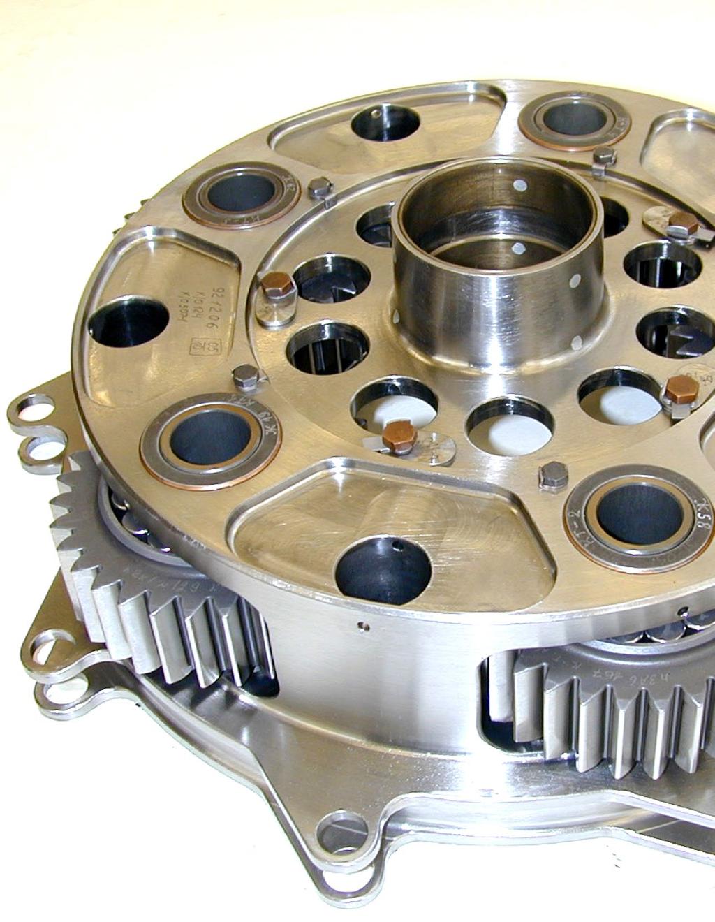
6 opposite direction. After the specified number of iterations, the optimization process stops, outputting the optimized fillet profile. During the optimization process, the fillet nodes cannot be moved inside the initial fillet profile because this may cause interference with the mating gear tooth tip. Figure 6 compares gear tooth stress distribution before and after root fillet optimization. Asymmetric epicyclic gear stage stress isograms and charts are shown in Figure 7. IMPLEMENTATION OF ASYMMETRIC EPICYCLIC TOOTH GEARS The first known application of epicyclic gears with asymmetric teeth was for the TV7-117S turboprop engine gearbox. The engine and gearbox were developed by Klimov Corporation (St. Petersburg, Russia) for the commuter airplane Ilyushin Il-114. The TV7-117S gearbox arrangement is shown in Figure 8. The first planetarydifferential stage has three planet gears. The second solar-type coaxial stage has five planet gears and stationary planet carrier. This arrangement is proved to provide the highest power transmission density for the required gear ratio. The main parameters and characteristics of this gearbox are described in Reference [3]. The first stage (without the sun gear) and the second stage carrier assembly of the TV7-117S turboprop engine gearbox are shown in Figure 9. CONCLUSION This article outlines the Direct Gear Design approach to asymmetric epicyclic gear stages with the singular and compound planet gears. Methods of optimization of the tooth flank asymmetry factor and root fillet profile are considered, and an example implementation of asymmetric epicyclic gears has been demonstrated. Figure 9: Assemblies of (a) first and (b) second stages of TV7-117S turboprop engine gearbox REFERENCES 1. V.N. Kudriavtsev, Y.N. Kirdiashev, Planetary Gears. Handbook. Mashinostroenie. Leningrad, Standard ISO 6336, Calculation of load capacity of spur and helical gears, A.L. Kapelevich, Direct Gear Design, CRC Press, A.L. Kapelevich, Y. V. Shekhtman. Tooth Fillet Profile Optimization for Gears with Symmetric and Asymmetric Teeth, Gear Technology, September/October, 2009, ABOUT THE AUTHOR: Dr. Alexander L. Kapelevich is the founder and president of the consulting firm AKGears, LLC, a developer of modern Direct Gear Design methodology and software. He has over 30 years of experience in custom gear transmission development, and he is the author of Direct Gear Design and many technical articles. Kapelevich can be reached by at ak@akgears.com. N-7036 AUGUST
INVOLUTE SPIRAL FACE COUPLINGS AND GEARS: DESIGN APPROACH AND MANUFACTURING TECHNIQUE
 УДК 621.9.015 Dr. Alexander L. Kapelevich, Stephen D. Korosec 38 INVOLUTE SPIRAL FACE COUPLINGS AND GEARS: DESIGN APPROACH AND MANUFACTURING TECHNIQUE This paper presents spiral face gears with an involute
Effect of Rim Thickness on Symmetric and Asymmetric Spur Gear Tooth Bending Stress
 NaCoMM-2009-### Effect of Rim Thickness on Symmetric and Asymmetric Spur Gear Tooth Bending Stress G. Mallesh 1*, Dr. V B Math 2, Ravitej 3, Krishna Prasad Bhat P 3, Paramesh Kumar M K 3 1 Assistant Professor,
GEAR CONTENTS POWER TRANSMISSION GEAR TYPES OF GEARS NOMENCLATURE APPLICATIONS OF GEARS VELOCITY RATIO GEAR TRAINS EXAMPLE PROBLEMS AND QUESTIONS
 GEAR CONTENTS POWER TRANSMISSION GEAR TYPES OF GEARS NOMENCLATURE APPLICATIONS OF GEARS VELOCITY RATIO GEAR TRAINS EXAMPLE PROBLEMS AND QUESTIONS GEAR.. Power transmission is the movement of energy from
Effect of Pressure Angle on Bending Stress and Deformation of Asymmetric Spur Gear Using FEA
 Effect of Pressure Angle on Bending Stress and Deformation of Asymmetric Spur Gear Using FEA MR. K. D. DADHANIYA, PROF. K. P. HIRPAR, MR. K. M. VYAS M.E.[Machine Design] Student, Department Of Mechanical
Introduction. Kinematics and Dynamics of Machines. Involute profile. 7. Gears
 Introduction The kinematic function of gears is to transfer rotational motion from one shaft to another Kinematics and Dynamics of Machines 7. Gears Since these shafts may be parallel, perpendicular, or
Design of Helical Gear and Analysis on Gear Tooth
 Design of Helical Gear and Analysis on Gear Tooth Indrale Ratnadeep Ramesh Rao M.Tech Student ABSTRACT Gears are mainly used to transmit the power in mechanical power transmission systems. These gears
CHAPTER 5 PREVENTION OF TOOTH DAMAGE IN HELICAL GEAR BY PROFILE MODIFICATION
 90 CHAPTER 5 PREVENTION OF TOOTH DAMAGE IN HELICAL GEAR BY PROFILE MODIFICATION 5.1 INTRODUCTION In any gear drive the absolute and the relative transmission error variations normally increases with an
ANALYSIS OF SURFACE CONTACT STRESS FOR A SPUR GEAR OF MATERIAL STEEL 15NI2CR1MO28
 ANALYSIS OF SURFACE CONTACT STRESS FOR A SPUR GEAR OF MATERIAL STEEL 15NI2CR1MO28 D. S. Balaji, S. Prabhakaran and J. Harish Kumar Department of Mechanical Engineering, Chennai, India E-Mail: balajimailer@gmail.com
Finite element analysis of profile modified spur gear
 Finite element analysis of profile modified spur gear Sagar Gaur Mechanical Engineering Department, Institute of Technology, YashluvVirwani Mechanical Engineering Department, Institute of Technology, Rudresh
Chapter seven. Gears. Laith Batarseh
 Chapter seven Gears Laith Batarseh Gears are very important in power transmission between a drive rotor and driven rotor What are the functions of gears? - Transmit motion and torque (power) between shafts
Effect of Tooth Profile Modification In Asymmetric Spur Gear Tooth Bending Stress By Finite Element Analysis
 Effect of Tooth Profile Modification In Asymmetric Spur Gear Tooth Bending Stress By Finite Element Analysis G. Mallesh 1*, Dr. V B Math 2, Ashwij 3, Prabodh Sai Dutt R 3, Rajendra Shanbhag 3 1 Assistant
Gear Tooth Geometry - This is determined primarily by pitch, depth and pressure angle
 Gear Tooth Geometry - This is determined primarily by pitch, depth and pressure angle Addendum: The radial distance between the top land and the pitch circle. Addendum Circle: The circle defining the outer
What are the functions of gears? What is gear?
 8//0 hapter seven Laith atarseh are very important in power transmission between a drive rotor and driven rotor What are the functions of gears? - Transmit motion and torque (power) between shafts - Maintain
TECHNICAL PAPER. New Opportunities with Molded Gears. by: R.E. Kleiss, A.L. Kapelevich and N.J. Kleiss Jr., Kleiss Gears, Inc.
 01FTM9 New Opportunities with Molded Gears by: R.E. Kleiss, A.L. Kapelevich and N.J. Kleiss Jr., Kleiss Gears, Inc. American Gear Manufacturers Association TECHNICAL PAPER New Opportunities with Molded
Part VII: Gear Systems: Analysis
 Part VII: Gear Systems: Analysis This section will review standard gear systems and will provide the basic tools to perform analysis on these systems. The areas covered in this section are: 1) Gears 101:
SECTION 8 BEVEL GEARING
 SECTION 8 BEVEL GEARING For intersecting shafts, bevel gears offer a good means of transmitting motion and power. Most transmissions occur at right angles, Figure 8-1, but the shaft angle can be any value.
AN OPTIMAL PROFILE AND LEAD MODIFICATION IN CYLINDRICAL GEAR TOOTH BY REDUCING THE LOAD DISTRIBUTION FACTOR
 AN OPTIMAL PROFILE AND LEAD MODIFICATION IN CYLINDRICAL GEAR TOOTH BY REDUCING THE LOAD DISTRIBUTION FACTOR Balasubramanian Narayanan Department of Production Engineering, Sathyabama University, Chennai,
INCREASE IN FATIGUE LIFE OF SPUR GEAR BY INTRODUCING CIRCULAR STRESS RELIEVING FEATURE
 INTERNATIONAL JOURNAL OF MECHANICAL ENGINEERING AND International Journal of Mechanical Engineering and Technology (IJMET), ISSN 0976 6340(Print), ISSN 0976 6359(Online), Volume TECHNOLOGY 6, Issue 5,
ANALYSIS OF GEAR QUALITY CRITERIA AND PERFORMANCE OF CURVED FACE WIDTH SPUR GEARS
 8 FASCICLE VIII, 8 (XIV), ISSN 11-459 Paper presented at Bucharest, Romania ANALYSIS OF GEAR QUALITY CRITERIA AND PERFORMANCE OF CURVED FACE WIDTH SPUR GEARS Laurentia ANDREI 1), Gabriel ANDREI 1) T, Douglas
Program Internal Gear Set Profile Shift Coefficients With Zero Backlash Introduction
 Program 60-107 Internal Gear Set Profile Shift Coefficients With Zero Backlash Introduction The purpose of this model is to provide data for a gear set when the tooth thickness and/or the center distance
Aero-Engine Fan Gearbox Design
 The 16 th Israeli Symposium on Jet Engines and Gas Turbines November 9, 2017 Aero-Engine Fan Gearbox Design Presented by: Ilan Berlowitz BEDEK Aviation Group, Aircraft & Programs Division Israel Aerospace
Internal Gears. No. of teeth (60) Module (1) Others (Ring Gear) Type (Internal Gear) Material (S45C)
 Module (1) Others (Ring Gear) Type (Internal Gear) Material (S45C)") ph: (410)8-10 (0)68-180 fx: (410)8-142 (0)872-929 rfq form: http://mdmetric.com/rfq.htm Internal Internal Miter CP Racks & Pinions Racks Helical Spur SI Steel Internal SIR Steel Ring m0. ~ Page 184 m2
ph: (410)8-10 (0)68-180 fx: (410)8-142 (0)872-929 rfq form: http://mdmetric.com/rfq.htm Internal Internal Miter CP Racks & Pinions Racks Helical Spur SI Steel Internal SIR Steel Ring m0. ~ Page 184 m2
Optimization of Design Based on Tip Radius and Tooth Width to Minimize the Stresses on the Spur Gear with FE Analysis.
 Optimization of Design Based on Tip Radius and Tooth Width to Minimize the Stresses on the Spur Gear with FE Analysis. K.Ruthupavan M. Tech Sigma Consultancy Service 7-1-282/C/A/1, 104, First Floor Rajaiah
ORIGINAL RESEARCH ARTICLE
 Available online at http://www.journalijdr.com ISSN: 2230-9926 International Journal of Development Research Vol. 08, Issue, 07, pp. 21463-21470, July, 2018 ORIGINAL RESEARCH ARTICLE ORIGINAL RESEARCH
KISSsoft Tutorial 012: Sizing of a fine pitch Planetary Gear set. 1 Task. 2 Starting KISSsoft
 KISSsoft Tutorial: Sizing of a fine pitch Planetary Gear set KISSsoft Tutorial 012: Sizing of a fine pitch Planetary Gear set For Release: 10/2008 kisssoft-tut-012-e-sizing-of-planetary-gear-set.doc Last
Session #3 Gears: Force Transmission & Gear Trains. Dan Frey
 Session #3 Gears: Force Transmission & Gear Trains Dan Frey Today s Agenda Pass out second reading packet Pass out loaner laptops Introduce project teams Gears Force Transmission Gear Trains Survey HW
11/23/2013. Chapter 13. Gear Trains. Dr. Mohammad Suliman Abuhiba, PE
 Chapter 13 Gear Trains 1 2 13.2. Types of Gear Trains 1. Simple gear train 2. Compound gear train 3. Reverted gear train 4. Epicyclic gear train: axes of shafts on which the gears are mounted may move
Effect of Coefficient of Asymmetry on Strength and Contact Ratio of Asymmetric Helical Gear
 2017 IJSRSET Volume 3 Issue 1 Print ISSN: 2395-1990 Online ISSN : 2394-4099 Themed Section: Engineering and Technology Effect of Coefficient of Asymmetry on Strength and Contact Ratio of Asymmetric Helical
Rim Stress Analysis of Epicyclic Gearbox
 International Journal of Current Engineering and Technology E-ISSN 2277 4106, P-ISSN 2347-5161 2014 INPRESSCO, All Rights Reserved Available at http://inpressco.com/category/ijcet Research Article Mahendra
(POWER TRANSMISSION Methods)
") UNIT-5 (POWER TRANSMISSION Methods) It is a method by which you can transfer cyclic motion from one place to another or one pulley to another pulley. The ways by which we can transfer cyclic motion are:-
UNIT-5 (POWER TRANSMISSION Methods) It is a method by which you can transfer cyclic motion from one place to another or one pulley to another pulley. The ways by which we can transfer cyclic motion are:-
Influential Criteria on the Optimization of a Gearbox, with Application to an Automatic Transmission
 Influential Criteria on the Optimization of a Gearbox, with Application to an Automatic Transmission Peter Tenberge, Daniel Kupka and Thomas Panéro Introduction In the design of an automatic transmission
[Potghan*, 4.(8): August, 2015] ISSN: (I2OR), Publication Impact Factor: 3.785
![[Potghan*, 4.(8): August, 2015] ISSN: (I2OR), Publication Impact Factor: 3.785](/thumbs/78/77378612.jpg "[Potghan*, 4.(8): August, 2015] ISSN: (I2OR), Publication Impact Factor: 3.785") IJESRT INTERNATIONAL JOURNAL OF ENGINEERING SCIENCES & RESEARCH TECHNOLOGY STRESS REDUCTION BY INTRODUCING STRESS RELIEVING FEATURES OF SPUR GEAR USED IN LATHE HEADSTOCK Deepika Potghan*, Prof. Suman Sharma
IJESRT INTERNATIONAL JOURNAL OF ENGINEERING SCIENCES & RESEARCH TECHNOLOGY STRESS REDUCTION BY INTRODUCING STRESS RELIEVING FEATURES OF SPUR GEAR USED IN LATHE HEADSTOCK Deepika Potghan*, Prof. Suman Sharma
Copyright Notice. Small Motor, Gearmotor and Control Handbook Copyright Bodine Electric Company. All rights reserved.
 Copyright Notice Small Motor, Gearmotor and Control Handbook Copyright 1993-2003 Bodine Electric Company. All rights reserved. Unauthorized duplication, distribution, or modification of this publication,
M.E. Scholar (Design and Thermal), I.E.T-DAVV, Indore, M.P., India. 2
, I.E.T-DAVV, Indore, M.P., India. 2") IJESRT INTERNATIONAL JOURNAL OF ENGINEERING SCIENCES & RESEARCH TECHNOLOGY PARAMETRIC ANALYSIS OF SPUR GEAR TO DETERMINE THE EFFECT OF VARIATION OF R.P.M. AND PRESSURE ANGLE ON STRESS PRODUCED Yogendra
IJESRT INTERNATIONAL JOURNAL OF ENGINEERING SCIENCES & RESEARCH TECHNOLOGY PARAMETRIC ANALYSIS OF SPUR GEAR TO DETERMINE THE EFFECT OF VARIATION OF R.P.M. AND PRESSURE ANGLE ON STRESS PRODUCED Yogendra
Critical Review of Design of Planetary Gears and Gear Box
 Critical Review of Design of Planetary Gears and Gear Box Authors Prabhakar V Pawar 1, Prof. P. R. Kulkarni 2 Department of Mechanical Engineering, Walchand Institute of Technology, Ashok Chowk, Solapur-413006,
Chapter 7: Thermal Study of Transmission Gearbox
 Chapter 7: Thermal Study of Transmission Gearbox 7.1 Introduction The main objective of this chapter is to investigate the performance of automobile transmission gearbox under the influence of load, rotational
RELIABILITY IMPROVEMENT OF ACCESSORY GEARBOX BEVEL DRIVES Kozharinov Egor* *CIAM
 RELIABILITY IMPROVEMENT OF ACCESSORY GEARBOX BEVEL DRIVES Kozharinov Egor* *CIAM egor@ciam.ru Keywords: Bevel gears, accessory drives, resonance oscillations, Coulomb friction damping Abstract Bevel gear
Influence of Stress in Spur Gear at Root Fillet with Optimized Stress Relieving Feature of Different Shapes
 Influence of Stress in Spur Gear at Root Fillet with Optimized Stress Relieving Feature of Different Shapes Haider Ali M.Tech Scholar, Dept. of Mechanical & Automobile Engg., Sharda University, Greater
Estimation of Wear Depth on Normal Contact Ratio Spur Gear
 Middle-East Journal of Scientific Research 24 (S1): 38-42, 2016 ISSN 1990-9233 IDOSI Publications, 2016 DOI: 10.5829/idosi.mejsr.2016.24.S1.9 Estimation of Wear Depth on Normal Contact Ratio Spur Gear
SECTION 4 SPUR GEAR CALCULATIONS
 Function of α, or invα, is known as involute function. Involute function is very important in gear design. Involute function values can be obtained from appropriate tables. With the 3.1 Contact Ratio center
Design and Numerical Analysis of Optimized Planetary Gear Box
 IOSR Journal of Mechanical and Civil Engineering (IOSR-JMCE) e-issn: 2278-1684,p-ISSN: 2320-334X. 05-11 www.iosrjournals.org Design and Numerical Analysis of Optimized lanetary Gear Box S.B.Nandeppagoudar
ME6401 KINEMATICS OF MACHINERY UNIT- I (Basics of Mechanism)
") ME6401 KINEMATICS OF MACHINERY UNIT- I (Basics of Mechanism) 1) Define resistant body. 2) Define Link or Element 3) Differentiate Machine and Structure 4) Define Kinematic Pair. 5) Define Kinematic Chain.
ME6401 KINEMATICS OF MACHINERY UNIT- I (Basics of Mechanism) 1) Define resistant body. 2) Define Link or Element 3) Differentiate Machine and Structure 4) Define Kinematic Pair. 5) Define Kinematic Chain.
Paper Number: DETC
 Proceedings of the th ASME International Power Transmission and Gearing Conference DETC20 August 28-3, 20, Washington, DC, USA Paper Number: DETC20-48494 THE DYNAMIC SIMULATION AND ANALYSIS OF A CYCLOIDAL
Vibration Analysis of Gear Transmission System in Electric Vehicle
 Advanced Materials Research Online: 0-0- ISSN: 66-8985, Vols. 99-00, pp 89-83 doi:0.408/www.scientific.net/amr.99-00.89 0 Trans Tech Publications, Switzerland Vibration Analysis of Gear Transmission System
Stress Analysis of a Ring gear of Planetary Gearbox
 ISSN 2395-1621 Stress Analysis of a Ring gear of Planetary Gearbox #1 Sumit Phadtare, #2 Suresh Jadhav 1 sumph10@gmail.com #12 Mechanical Engineering, Veermata Jijabai Technological Institute Mumbai, Maharashtra,
Program Synchronic Index of In-line Geared Systems Introduction
 Program 60-151 Synchronic Index of In-line Geared Systems Introduction This TK Model calculates the synchronic index of an in-line geared transmission system. The synchronic index of a geared system is
STRUCTURAL ANALYSIS OF SPUR GEAR USING FEM
 International Journal of Mechanical Engineering and Technology (IJMET) Volume 7, Issue 6, November December 2016, pp.01 08, Article ID: IJMET_07_06_001 Available online at http://www.iaeme.com/ijmet/issues.asp?jtype=ijmet&vtype=7&itype=6
St.MARTIN S ENGINEERING COLLEGE Dhulapally, Secunderabad
 St.MARTIN S ENGINEERING COLLEGE Dhulapally, Secunderabad-500 014 Subject: Kinematics of Machines Class : MECH-II Group A (Short Answer Questions) UNIT-I 1 Define link, kinematic pair. 2 Define mechanism
Tooth Shape Optimization of the NGW31 Planetary Gear Based on Romax Designer
 6th International Conference on Electronics, Mechanics, Culture and Medicine (EMCM 2015) Tooth Shape Optimization of the NGW31 Planetary Gear Based on Romax Designer Chunming Xu 1, a *, Ze Liu 1, b, Wenjun
Lecture (7) on. Gear Measurement. By Dr. Emad M. Saad. Industrial Engineering Dept. Faculty of Engineering. Fayoum University.
 on. Gear Measurement. By Dr. Emad M. Saad. Industrial Engineering Dept. Faculty of Engineering. Fayoum University.") 1 Lecture (7) on Gear Measurement Fayoum University By Dr. Emad M. Saad Industrial Engineering Dept. Faculty of Engineering Fayoum University Faculty of Engineering Industrial Engineering Dept. 2015-2016
1 Lecture (7) on Gear Measurement Fayoum University By Dr. Emad M. Saad Industrial Engineering Dept. Faculty of Engineering Fayoum University Faculty of Engineering Industrial Engineering Dept. 2015-2016
MULTITHREADED CONTINUOUSLY VARIABLE TRANSMISSION SYNTHESIS FOR NEXT-GENERATION HELICOPTERS
 MULTITHREADED CONTINUOUSLY VARIABLE TRANSMISSION SYNTHESIS FOR NEXT-GENERATION HELICOPTERS Kalinin D.V. CIAM, Russia Keywords: high-speed helicopter, transmission, CVT Abstract The results of analysis
Design and Analysis of Gearbox for Tractor Transmission System
 ISSN 2395-62 Design and Analysis of box for Tractor Transmission System # Rahul Mokal, #2 R.V. Mulik, #3 S.B. Sanap rbmokal3.scoe@gmail.com 2 mulik.edl@araiindia.com 3 sbsanap.scoe@sinhgad.edu #3 Sinhgad
2. a) What is pantograph? What are its uses? b) Prove that the peaucellier mechanism generates a straight-line motion. (5M+10M)
 What is pantograph? What are its uses? b) Prove that the peaucellier mechanism generates a straight-line motion. (5M+10M)") Code No: R22032 R10 SET - 1 1. a) Define the following terms? i) Link ii) Kinematic pair iii) Degrees of freedom b) What are the inversions of double slider crank chain? Describe any two with neat sketches.
Code No: R22032 R10 SET - 1 1. a) Define the following terms? i) Link ii) Kinematic pair iii) Degrees of freedom b) What are the inversions of double slider crank chain? Describe any two with neat sketches.
CASE STUDY OF ASSEMBLY ERRORS INFLUENCE ON STRESS DISTRIBUTION IN SPUR GEAR TRAIN
 Proceedings of the 7th International Conference on Mechanics and Materials in Design Albufeira/Portugal 11-15 June 2017. Editors J.F. Silva Gomes and S.A. Meguid. Publ. INEGI/FEUP (2017) PAPER REF: 6564
Benefits of Asymmetric Gears LIEBHERR EXAMINES PRODUCTIVITY AND QUALITY ADVANTAGES
 product news Benefits of Asymmetric Gears LIEBHERR EXAMINES PRODUCTIVITY AND QUALITY ADVANTAGES Gear wheels often rotate in only one direction throughout their entire service lives. This applies particularly
Methodology for Designing a Gearbox and its Analysis
 Methodology for Designing a Gearbox and its Analysis Neeraj Patel, Tarun Gupta B.Tech, Department of Mechanical Engineering, Maulana Azad National Institute of Technology, Bhopal, India. Abstract Robust
bearing to conform to the same elliptical shape as the wave generator plug.
 32 Gear Product News April 2006 t h e b a s i c s o f H a r m o n i c D r i v e G e a r i n g Anthony Lauletta H armonic drives were invented in the late 1950s and have been a major part of the motion
A COMPARATIVE STUDY OF DESIGN OF SIMPLE SPUR GEAR TRAIN AND HELICAL GEAR TRAIN WITH A IDLER GEAR BY AGMA METHOD
 A COMPARATIVE STUDY OF DESIGN OF SIMPLE SPUR GEAR TRAIN AND HELICAL GEAR TRAIN WITH A IDLER GEAR BY AGMA METHOD Miss. Kachare Savita M.E. Student of Mechanical Design Engg, VACOE, Ahmednagar, India Savita_K90@rediffmail.com
Contact Stress Analysis for 'Gear' to Optimize Mass using CAE Techniques
 Contact Stress Analysis for 'Gear' to Optimize Mass using CAE Techniques Mr.Alkunte Suhas Suryakant Prof. S.Y.Gajjal Prof. D.A.Mahajan PG Student Mechanical Department, HOD, Mechanical Department, Mechanical
Determination and improvement of bevel gear efficiency by means of loaded TCA
 Determination and improvement of bevel gear efficiency by means of loaded TCA Dr. J. Thomas, Dr. C. Wirth, ZG GmbH, Germany Abstract Bevel and hypoid gears are widely used in automotive and industrial
Chapter 3. Transmission Components
 Chapter 3. Transmission Components The difference between machine design and structure design An important design problem in a mechanical system is how to transmit and convert power to achieve required
STRESS ANALYSIS FOR SPUR GEARS USING SOLID WORKS SIMULATION
 International Journal of Mechanical Engineering and Technology (IJMET) Volume 9, Issue 11, November 2018, pp. 927 936, Article ID: IJMET_09_11_094 Available online at http://www.iaeme.com/ijmet/issues.asp?jtype=ijmet&vtype=9&itype=11
Thermal Analysis of Helical and Spiral Gear Train
 International Journal for Ignited Minds (IJIMIINDS) Thermal Analysis of Helical and Spiral Gear Train Dr. D V Ghewade a, S S Nagarale b & A N Pandav c a Principal, Department of Mechanical, GENESIS, Top-Kolhapur,
Design of Pneumatic Rotary Actuator Spur Pinion in Worst Loading Condition with Different Material
 Design of Pneumatic Rotary Actuator Spur Pinion in Worst Loading Condition with Different Material Mr. Prashant Vavhal 1, Prof. Kiran More 2, Prof. N.R. Jadhao 3 1 PG Student, Department Of Mechanical
Chapter 8 Kinematics of Gears
 Chapter 8 Kinematics of Gears Gears! Gears are most often used in transmissions to convert an electric motor s high speed and low torque to a shaft s requirements for low speed high torque: Speed is easy
Case Study Involving Surface Durability and Improved Surface Finish
 Case Study Involving Surface Durability and Improved Surface Finish G. Blake and J. Reynolds (Printed with permission of the copyright holder, the American Gear Manufacturers Association, 500 Montgomery
Mechanism Feasibility Design Task
 Mechanism Feasibility Design Task Dr. James Gopsill 1 Contents 1. Last Week 2. Types of Gear 3. Gear Definitions 4. Gear Forces 5. Multi-Stage Gearbox Example 6. Gearbox Design Report Section 7. This Weeks
Code No: R Set No. 1
 Code No: R05222106 Set No. 1 II B.Tech II Semester Supplimentary Examinations, Aug/Sep 2007 MECHANISMS AND MECHANICAL DESIGN (Aeronautical Engineering) Time: 3 hours Max Marks: 80 Answer any FIVE Questions
Tribology Aspects in Angular Transmission Systems
 Tribology Aspects in Angular Transmission Systems Part II Straight Bevel Gears Dr. Hermann Stadtfeld (This is the second of an eight-part series on the tribology aspects of angular gear drives. Each article
Different types of gears. Spur gears. Idler gears. Worm gears. Bevel gears. Belts & Pulleys
 GEARS Robot Gears By using different gear diameters, you can exchange between rotational (or translation) velocity and torque. by looking at the motor datasheet you can determine the output velocity and
Hybrid Transmission with Simple Planetary Gear
 Hybrid Transmission with Simple Planetary Gear Vladimir Ivanovich Nekrasov 1, Ruslan Albertovich Ziganshin 2, Oksana Olegovna Gorshkova 3, Mikhail Mikhailovich Ivankiv 4 1, 2, 3 Tyumen Industrial University,
Design and Manufacturing of Indexing Fixture For Piston Compressor Block
 Design and Manufacturing of Indexing Fixture For Piston Compressor Block Prof. G.E. Kondhalkar 1, Ganesh Kale 2, Aditya Kamble 3, Kunal Kshirsagar 4, Sarang Upasani 5 1 HOD Mechanical Dept, Anantrao Pawar
Precision on the highest level
 6 - line Precision on the highest level The series is the standard Neugart inline high precision planetary gearhead for applications with very high precision requirements. Whether high torque density,
Static And Modal Analysis of Tractor Power Take Off (PTO) Gearbox Housing
 Gearbox Housing") Static And Modal Analysis of Tractor Power Take Off (PTO) Gearbox Housing Gopali S Lamani 1, Prof: S.R.Basavaraddi 2, Assistant Professor, Department of Mechanical Engineering, JSPM NTC RSSOER,India1 Professor,
Static And Modal Analysis of Tractor Power Take Off (PTO) Gearbox Housing Gopali S Lamani 1, Prof: S.R.Basavaraddi 2, Assistant Professor, Department of Mechanical Engineering, JSPM NTC RSSOER,India1 Professor,
CHENDU COLLEGE OF ENGINEERING & TECHNOLOGY DEPARTMENT OF MECHANICAL ENGINEERING QUESTION BANK IV SEMESTER
 CHENDU COLLEGE OF ENGINEERING & TECHNOLOGY DEPARTMENT OF MECHANICAL ENGINEERING QUESTION BANK IV SEMESTER Sub Code: ME 6401 KINEMATICS OF MACHINERY UNIT-I PART-A 1. Sketch and define Transmission angle
1874. Effect predictions of star pinion geometry phase adjustments on dynamic load sharing behaviors of differential face gear trains
 1874. Effect predictions of star pinion geometry phase adjustments on dynamic load sharing behaviors of differential face gear trains Zhengminqing Li 1, Wei Ye 2, Linlin Zhang 3, Rupeng Zhu 4 Nanjing University
ANALYSIS OF STRESS RELIEVING FEATURES OF ASYMMETRIC SPUR GEAR
 ANALYSIS OF STRESS RELIEVING FEATURES OF ASYMMETRIC SPUR GEAR Prof.G.B.Ingole P.G student, Mechanical Engineering Department, Sinhgad College of Engineering, Pune, Savitribai Phule Pune University, India.
GatesFacts Technical Information Library Gates Compass Power Transmission CD-ROM version 1.2 The Gates Rubber Company Denver, Colorado USA
 Gary L. Miller Plant Engineering November 7, 1991 DIFFERENCES IN SYNCHRONOUS BELTS All toothed belts are not the same; subtle differences in tooth profiles and construction affect performance. Synchronous
DESIGN OF TWO STAGE PLANETARY GEAR TRAIN FOR HIGH REDUCTION RATIO
 DESIGN OF TWO STAGE PLANETARY GEAR TRAIN FOR HIGH REDUCTION RATIO Prabhakar Vitthal Pawar 1, P.R. Kulkarni 2 1 M.E. (Design ), Mechanical Engineering, Walchand Institute of Technology, Solapur-413003,
Numerical check of a 2DOF transmission for wind turbines
 Numerical check of a 2DOF transmission for wind turbines Beibit Shingissov 1, Gani Balbayev 2, Shynar Kurmanalieva 3, Algazy Zhauyt 4, Zhanar Koishybayeva 5 1, 2 Almaty University of Power Engineering
A comparison of the gear calculation process according to Swedish and American textbooks for higher education
 World Transactions on Engineering and Technology Education Vol.6, No.1, 2007 2007 UICEE A comparison of the gear calculation process according to Swedish and American textbooks for higher education Samir
 DEPARTMENT OF MECHANICAL ENGINEERING Subject code: ME6601 Subject Name: DESIGN OF TRANSMISSION SYSTEMS UNIT-I DESIGN OF TRANSMISSION SYSTEMS FOR FLEXIBLE ELEMENTS 1. What is the effect of centre distance
KINGS COLLEGE OF ENGINEERING DEPARTMENT OF MECHANICAL ENGINEERING
 KINGS COLLEGE OF ENGINEERING DEPARTMENT OF MECHANICAL ENGINEERING QUESTION BANK Sub Code/Name: ME 1352 DESIGN OF TRANSMISSION SYSTEMS Year/Sem: III / VI UNIT-I (Design of transmission systems for flexible
Spur gearing, Helical gearing [mm/iso] Pinion Gear ii Project information? i Calculation without errors.
![Spur gearing, Helical gearing [mm/iso] Pinion Gear ii Project information? i Calculation without errors.](/thumbs/80/81955134.jpg "Spur gearing, Helical gearing [mm/iso] Pinion Gear ii Project information? i Calculation without errors.") S Spur gearing, Helical gearing [mm/iso] i Calculation without errors. Pinion Gear ii Project information? Input section 1. Options of basic input parameters 1.1 Transferred power Pw [kw] 9.67 9.63 1.2
S Spur gearing, Helical gearing [mm/iso] i Calculation without errors. Pinion Gear ii Project information? Input section 1. Options of basic input parameters 1.1 Transferred power Pw [kw] 9.67 9.63 1.2
An investigation on development of Precision actuator for small robot
 An investigation on development of Precision actuator for small robot Joo Han Kim*, Se Hyun Rhyu, In Soung Jung, Jung Moo Seo Korea Electronics Technology Institute (KETI) * 203-103 B/D 192 Yakdae-Dong,
Internal vibration monitoring of a Planetary Gearbox
 Internal vibration monitoring of a Planetary Gearbox Marc R. de Smidt M-Eng (Mechanical) What is a Planetary or Epicyclic Gearbox? Ring / Annulus gear Planet gears on Planet carrier Sun gear How does it
o f Tip Relief on Transmission
 E v a l u a t i o n o f M e t h o d s f o r C a l c u l a t i n g E f f e c t s o f Tip Relief on Transmission E r r o r, N o i s e a n d S t r e s s i n L o a d e d S p u r G e a r s Dr. David Palmer
The Geometry of Involute Gears
 The Geometry of Involute Gears J.R. Colbourne The Geometry of Involute Gears With 217 Illustrations Springer-Verlag New York Berlin Heidelberg London Paris Tokyo J.R. Colbourne Department of Mechanical
ANALYSIS OF STRESSES AND DEFLECTIONS IN SPUR GEAR
 International Journal of Mechanical Engineering and Technology (IJMET) Volume 8, Issue 4, April 2017, pp. 461 473 Article ID: IJMET_08_04_050 Available online at http://www.iaeme.com/ijmet/issues.asp?jtype=ijmet&vtype=8&itype=4
Stress Analysis of Spur Gear by using Different Materials: A Review
 Stress Analysis of Spur Gear by using Different Materials: A Review Ms. Nilesha U. Patil 1*, Mr. Sunil P. Chaphalkar 2,Mr. Gajanan L. Chaudhari 3 1 ME Student, Department of Mechanical Engineering, APCOER,
Experimental Analyses of Vibration and Noise of Faulted Planetary Gearbox
 Experimental Analyses of Vibration and Noise of Faulted Planetary Gearbox Zhuang Li McNeese State University, USA e-mail: zli@mcneese.edu ABSTRACT Epicyclic gear trains are widely used in various industrial
A Comparison of Spur Gear Response under Non-Ideal Loading Conditions
 Paper Number A Comparison of Spur Gear Response under Non-Ideal Loading Conditions Nam H. Kim, Kyle Stoker University of Florida Copyright 2008 SAE International ABSTRACT The current practice of gear design
Analysis of Torsional Vibration in Elliptical Gears
 The The rd rd International Conference on on Design Engineering and Science, ICDES Pilsen, Czech Pilsen, Republic, Czech August Republic, September -, Analysis of Torsional Vibration in Elliptical Gears
1. (a) Discuss various types of Kinematic links with examples. (b) Explain different types of constrained motions with examples.
 Discuss various types of Kinematic links with examples. (b) Explain different types of constrained motions with examples.") Code No: RR310304 Set No. 1 III B.Tech I Semester Supplementary Examinations, February 2007 KINEMATICS OF MACHINERY ( Common to Mechanical Engineering, Mechatronics and Production Engineering) Time: 3
Code No: RR310304 Set No. 1 III B.Tech I Semester Supplementary Examinations, February 2007 KINEMATICS OF MACHINERY ( Common to Mechanical Engineering, Mechatronics and Production Engineering) Time: 3
Determination of the optimum flank line modifications for gear pairs and for planetary stages
 Determination of the optimum flank line modifications for gear pairs and for planetary stages Authors: Dr. Ing. Ulrich Kissling, KISSsoft AG Dipl. Ing. Hanspeter Dinner, EES-KISSsoft GmbH KISSsoft AG Rosengartenstrasse
Code No: R Set No. 1
 Code No: R05310304 Set No. 1 III B.Tech I Semester Regular Examinations, November 2007 KINEMATICS OF MACHINERY ( Common to Mechanical Engineering, Mechatronics, Production Engineering and Automobile Engineering)
Instantaneous Centre Method
 Instantaneous Centre Method The combined motion of rotation and translation of the link AB may be assumed to be a motion of pure rotation about some centre I, known as the instantaneous centre of rotation.
Siddhant Dange 1, Saket Sant 2, Anish Sali 3, Parthan Pethodam 4, Mr. Sandeep Belgamwar 5
 International Journal of Latest Research in Engineering and Technology (IJLRET) ISSN: 2454-5031 ǁ Volume 2 Issue 4ǁ April 2016 ǁ PP 41-45 Design and Analysis of Planetary Gearbox for Industrial Concrete
Performance Study and Mathematical Model of Aerospace Geared Rotary Actuators
 International Journal of Applied Engineering Research ISSN 0973-456 Volume 3, Number (08) pp. 67-74 Performance Study and Mathematical Model of Aerospace Geared Rotary Actuators Alessandro Bertucci, Giovanni
Customer Application Examples
 Customer Application Examples The New, Powerful Gearwheel Module 1 SIMPACK Usermeeting 2006 Baden-Baden 21. 22. March 2006 The New, Powerful Gearwheel Module L. Mauer INTEC GmbH Wessling Customer Application