Instantaneous Centre Method
|
|
|
- Bryce Poole
- 5 years ago
- Views:
Transcription


1 Instantaneous Centre Method The combined motion of rotation and translation of the link AB may be assumed to be a motion of pure rotation about some centre I, known as the instantaneous centre of rotation. Since the points A and B of the link has moved to A1 and B1 respectively under the motion of rotation (as assumed above), therefore the position of the centre of rotation must ie on the intersection of the right bisectors of chords AA1 and BB1. Let these bisectors intersect at I as shown in Figure, which is the instantaneous centre of rotation or virtual centre of the link AB.
2 Instantaneous Centre Method The instantaneous centre of a moving body may be defined as that centre which goes on changing from one instant to another. The locus of all such instantaneous centres is known as centrode. A line drawn through an instantaneous centre and perpendicular to the plane of motion is called instantaneous axis. The locus of this axis is known as axode.

3 Velocity of a Point on a Link by Instantaneous Centre Method 1. If va is known in magnitude and direction and vb in direction only, then velocity of point B or any other point C lying on the same link may be determined in magnitude and direction. 2. The magnitude of velocities of the points on a rigid link is inversely proportional to the distances from the points to the instantaneous centre and is perpendicular to the line joining the point to the instantaneous centre.
4 Properties of the Instantaneous Centre 1. A rigid link rotates instantaneously relative to another link at the instantaneous centre for the configuration of the mechanism considered. 2. The two rigid links have no linear velocity relative to each other at the instantaneous centre. At this point (i.e. instantaneous centre), the two rigid links have the same linear velocity relative to the third rigid link. In other words, the velocity of the instantaneous centre relative to any third rigid link will be same whether the instantaneous centre is regarded as a point on the first rigid link or on the second rigid link.
5 Number of Instantaneous Centres in a Mechanism
6 Types of Instantaneous Centres The instantaneous centres for a mechanism are of the following three types : 1. Fixed instantaneous centres, 2. Permanent instantaneous centres, and 3. Neither fixed nor permanent instantaneous centres. The first two types i.e. fixed and permanent instantaneous centres are together known as primary instantaneous centres and the third type is known as secondary instantaneous centres.
7 Types of Instantaneous Centres I12 and I14:fixed instantaneous centres as they remain I23 and I34:permanent instantaneous centres I13 and I24:neither fixed nor permanent instantaneous centres
8 Location of Instantaneous Centres
9 Aronhold Kennedy (or Three Centres in Line) Theorem The Aronhold Kennedy s theorem states that if three bodies move relatively to each other, they have three instantaneous centres and lie on a straight line.
10 Method of Locating Instantaneous Centres in a Mechanism
11 Example 6.1: Khurmi The crank AB rotates uniformly at 100 r.p.m. Locate all the instantaneous centres and find the angular velocity of the link BC.
12 Solution
13 Example 6.2: Khurmi If the crank rotates clockwise with an angular velocity of 10 rad/s, find: 1. Velocity of the slider A,and 2. Angular velocity of the connecting rod AB.
14 Solution
15
16 Module 4 Kinematics of Cams How to convert Rotary Motion to Translational Motion??? Think
17 Crank Slider Mechanism Rack and Pinion Cam Follower
18 Introduction A cam is a rotating machine element which gives reciprocating or oscillating motion to another element known as follower. The cam and the follower have a line contact and constitute a higher pair. The cams are usually rotated at uniform speed by a shaft, but the follower motion is predetermined and will be according to the shape of the cam. The cams are widely used for operating the inlet and exhaust valves of internal combustion engines, automatic attachment of machineries, paper cutting machines, spinning and weaving textile machineries, feed mechanism of automatic lathes etc.
19 Classification of Followers 1. According to the surface in contact. 2. According to the motion of the follower. 3. According to the path of motion of the follower.
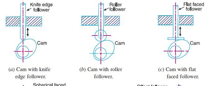
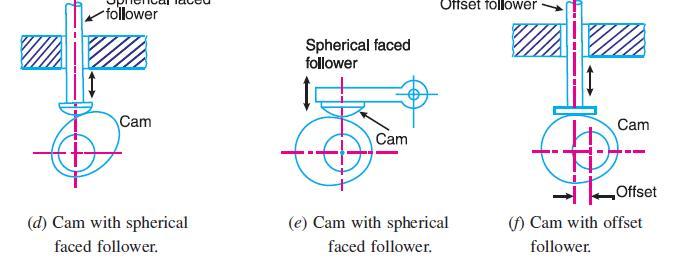
20 According to the surface in contact (a) Knife edge follower (b) Roller follower (c) Flat faced or mushroom follower (When the flat faced follower is circular, it is then called a mushroom follower) (d) Spherical faced follower
21
 Reciprocating or")
 Oscillating or rotating")
22 According to the motion of the follower (a) Reciprocating or translating follower: Case a to d,f (b) Oscillating or rotating follower: Case e
23 According to the path of motion of the follower (a) Radial follower (b) Off-set follower (a) to (e) are all radial followers ( f ) is an off-set follower.
24 Classification of Cams 1. Radial or disc cam (all the cams shown earlier) 2. Cylindrical cam
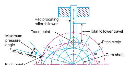
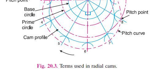
25 Terms Used in Radial Cams 1. Base circle. It is the smallest circle that can be drawn to the cam profile. 2. Trace point. It is a reference point on the follower and is used to generate the pitch curve. In case of knife edge follower, the knife edge represents the trace point and the pitch curve corresponds to the cam profile. In a roller follower, the centre of the roller represents the trace point. 3. Pressure angle. It is the angle between the direction of the follower motion and a normal to the pitch curve. This angle is very important in designing a cam profile. If the pressure angle is too large, a reciprocating follower will jam in its bearings.
26 4. Pitch point. It is a point on the pitch curve having the maximum pressure angle. 5. Pitch circle. It is a circle drawn from the centre of the cam through the pitch points. 6. Pitch curve. It is the curve generated by the trace point as the follower moves relative to the cam. For a knife edge follower, the pitch curve and the cam profile are same whereas for a roller follower, they are separated by the radius of the roller. 7. Prime circle. It is the smallest circle that can be drawn from the centre of the cam and tangent to the pitch curve. For a knife edge and a flat face follower, the prime circle and the base circle are identical. For a roller follower, the prime circle is larger than the base circle by the radius of the roller. 8. Lift or stroke. It is the maximum travel of the follower from its lowest position to the topmost position.
27
28 Motion of the Follower 1. Uniform velocity, 2. Simple harmonic motion, 3. Uniform acceleration and retardation, and 4. Cycloidal motion. We shall now discuss the displacement, velocity and acceleration diagrams for the cam when the follower moves with the above mentioned motions.
29 Displacement, Velocity and Acceleration Diagrams when the Follower Moves with Uniform Velocity

30 Displacement, Velocity and Acceleration Diagrams when the Follower Moves with Simple Harmonic Motion
31 Displacement, Velocity and Acceleration Diagrams when the Follower Moves with Simple Harmonic Motion The displacement diagram is drawn as follows : 1. Draw a semi-circle on the follower stroke as diameter. 2. Divide the semi-circle into any number of even equal parts (say eight). 3. Divide the angular displacements of the cam during out stroke and return stroke into the same number of equal parts. 4. The displacement diagram is obtained by projecting the points as shown in Figure

32 Displacement, Velocity and Acceleration Diagrams when the Follower Moves with Simple Harmonic Motion
33

34 Displacement, Velocity and Acceleration Diagrams when the Follower Moves with Uniform Acceleration and Retardation
35 Displacement, Velocity and Acceleration Diagrams when the Follower Moves with Uniform Acceleration and Retardation 1. Divide the angular displacement of the cam during outstroke ( O ) into any even number of equal parts (say eight) and draw vertical lines through these points as shown in Figure. 2. Divide the stroke of the follower (S) into the same number of equal even parts. 3. Join Aa to intersect the vertical line through point 1 at B. Similarly, obtain the other points C, D etc. as shown in Fig (a). Now join these points to obtain the parabolic curve for the out stroke of the follower. 4. In the similar way as discussed above, the displacement diagram for the follower during return stroke may be drawn.

36 Displacement, Velocity and Acceleration Diagrams when the Follower Moves with Cycloidal Motion
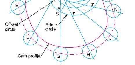
37 Construction of Cam Profile for a Radial Cam In constructing the cam profile, the principle of kinematic inversion is used, i.e. the cam is imagined to be stationary and the follower is allowed to rotate in the opposite direction to the cam rotation.
38 Types of Problems (Radial Cams, Reciprocating Followers) They will be a combination of the following three: Motion of the Follower Type of Follower 1.Uniform velocity a. Knife-edged Follower 2. Simple harmonic b. Roller Follower motion c. Flat-faced Follower 3. Uniform acceleration and retardation, and 4. Cycloidal motion Cases i. the axis of the follower passes through the axis of the cam shaft (Radial follower) ii. the axis of the follower is offset by 20 mm from the axis of the cam shaft (Off-set follower)
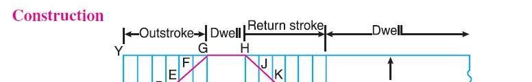
39 Example (Khurmi) A cam is to give the following motion to a knife-edged follower : 1. Outstroke during 60 of cam rotation ; 2. Dwell for the next 30 of cam rotation ; 3. Return stroke during next 60 of cam rotation, and 4. Dwell for the remaining 210 of cam rotation. The stroke of the follower is 40 mm and the minimum radius of the cam is 50 mm. The follower moves with uniform velocity during both the outstroke and return strokes. Draw the profile of the cam when (a) the axis of the follower passes through the axis of the cam shaft, and (b) the axis of the follower is offset by 20 mm from the axis of the cam shaft.
40


41 (a) Profile of the cam when the axis of follower passes through the axis of cam shaft

42 (b) Profile of the cam when the axis of the follower is offset by 20 mm from the axis of the cam shaft
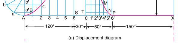
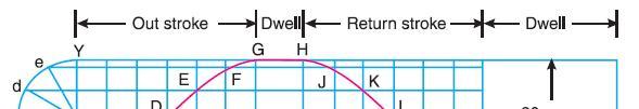
43 Example (Khurmi) A cam is to be designed for a knife edge follower with the following data : 1. Cam lift = 40 mm during 90 of cam rotation with simple harmonic motion. 2. Dwell for the next During the next 60 of cam rotation, the follower returns to its original position with simple harmonic motion. 4. Dwell during the remaining 180. Draw the profile of the cam when (a) the line of stroke of the follower passes through the axis of the cam shaft, and (b) the line of stroke is offset 20 mm from the axis of the cam shaft. The radius of the base circle of the cam is 40 mm. Determine the maximum velocity and acceleration of the follower during its ascent and descent, if the cam rotates at 240 r.p.m.
44


45 (a) Profile of the cam when the line of stroke of the follower passes through the axis of the camshaft

46 (b) Profile of the cam when the line of stroke of the follower is offset 20 mm from the axis of the camshaft
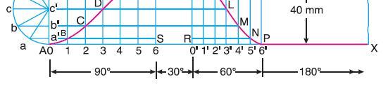
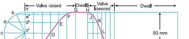
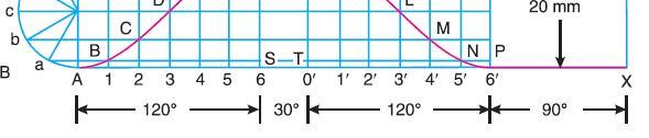
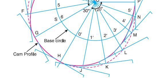
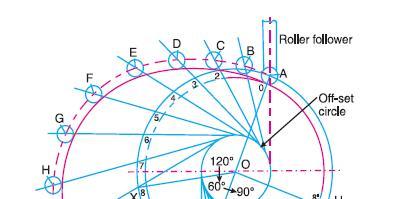
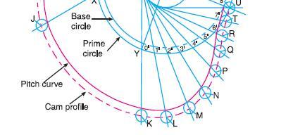
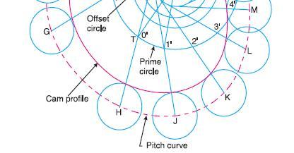
47 Example (Khurmi) A cam, with a minimum radius of 25 mm, rotating clockwise at a uniform speed is to be designed to give a roller follower, at the end of a valve rod, motion described below : 1. To raise the valve through 50 mm during 120 rotation of the cam ; 2. To keep the valve fully raised through next 30 ; 3. To lower the valve during next 60 ; and 4. To keep the valve closed during rest of the revolution i.e. 150 ; The diameter of the roller is 20 mm and the diameter of the cam shaft is 25 mm. Draw the profile of the cam when (a) the line of stroke of the valve rod passes through the axis of the cam shaft, and (b) the line of the stroke is offset 15 mm from the axis of the cam shaft. The displacement of the valve, while being raised and lowered, is to take place with simple harmonic motion. Determine the maximum acceleration of the valve rod when the cam shaft rotates at 100 r.p.m. Draw the displacement, the velocity and the acceleration diagrams for one complete revolution of the cam.
48


49 (a) Profile of the cam when the line of stroke of the valve rod passes through the axis of the camshaft


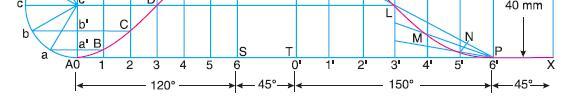
50 (b) Profile of the cam when the line of stroke is offset 15 mm from the axis of the camshaft
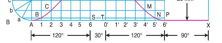
51 Example (Khurmi) A cam drives a flat reciprocating follower in the following manner : During first 120 rotation of the cam, follower moves outwards through a distance of 20 mm with simple harmonic motion. The follower dwells during next 30 of cam rotation. During next 120 of cam rotation, the follower moves inwards with simple harmonic motion. The follower dwells for the next 90 of cam rotation. The minimum radius of the cam is 25 mm. Draw the profile of the cam.
52
53
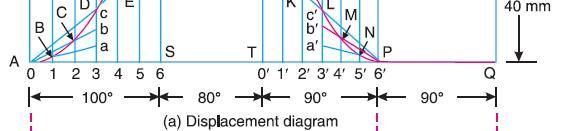
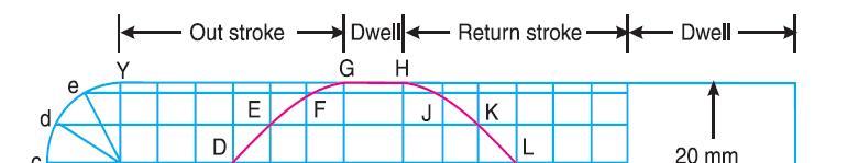
54 Example (Khurmi) A cam, with a minimum radius of 50 mm, rotating clockwise at a uniform speed, is required to give a knife edge follower the motion as described below 1. To move outwards through 40 mm during 100 rotation of the cam ; 2. To dwell for next 80 ; 3. To return to its starting position during next 90, and 4. To dwell for the rest period of a revolution i.e. 90. Draw the profile of the cam (i) when the line of stroke of the follower passes through the centre of the cam shaft, and (ii) when the line of stroke of the follower is off-set by 15 mm. The displacement of the follower is to take place with uniform acceleration and uniform retardation. Determine the maximum velocity and acceleration of the follower when the cam shaft rotates at 900 r.p.m. Draw the displacement, velocity and acceleration diagrams for one complete revolution of the cam.
55

56 a) Profile of the cam when the line of stroke of the follower passes through the centre of the camshaft

57 b) Profile of the cam when the line of stroke of the follower is offset by 15 mm
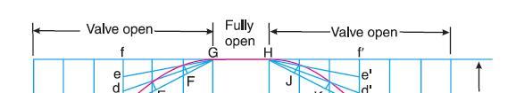
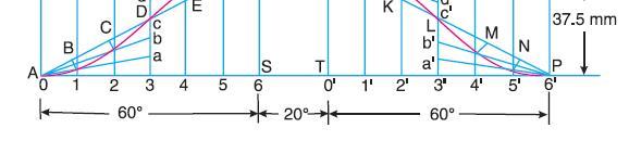
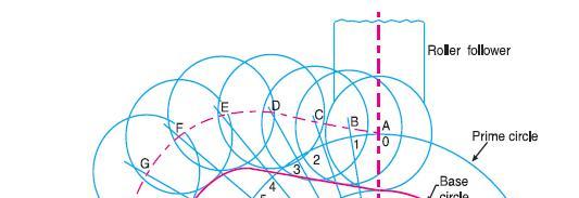
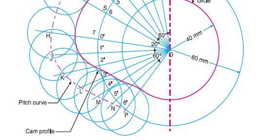
58 Example (Khurmi) Design a cam for operating the exhaust valve of an oil engine. It is required to give equal uniform acceleration and retardation during opening and closing of the valve each of which corresponds to 60 of cam rotation. The valve must remain in the fully open position for 20 of cam rotation. The lift of the valve is 37.5 mm and the least radius of the cam is 40 mm. The follower is provided with a roller of radius 20 mm and its line of stroke passes through the axis of the cam.
59
60
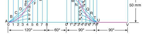
61 Example (Khurmi) A cam rotating clockwise at a uniform speed of 1000 r.p.m. is required to give a roller follower the motion defined below : 1. Follower to move outwards through 50 mm during 120 of cam rotation, 2. Follower to dwell for next 60 of cam rotation, 3. Follower to return to its starting position during next 90 of cam rotation, 4. Follower to dwell for the rest of the cam rotation. The minimum radius of the cam is 50 mm and the diameter of roller is 10 mm. The line of stroke of the follower is off-set by 20 mm from the axis of the cam shaft. If the displacement of the follower takes place with uniform and equal acceleration and retardation on both the outward and return strokes, draw profile of the cam and find the maximum velocity and acceleration during out stroke and return stroke.
62
63
64 Example (Khurmi) Construct the profile of a cam to suit the following specifications : Cam shaft diameter = 40 mm ; Least radius of cam = 25 mm ; Diameter of roller = 25 mm; Angle of lift = 120 ; Angle of fall = 150 ; Lift of the follower = 40 mm ; Number of pauses are two of equal interval between motions. During the lift, the motion is S.H.M. During the fall the motion is uniform acceleration and deceleration. The speed of the cam shaft is uniform. The line of stroke of the follower is off-set 12.5 mm from the centre of the cam.
65
66
67 Example (Khurmi) It is required to set out the profile of a cam to give the following motion to the reciprocating follower with a flat mushroom contact face : (i) Follower to have a stroke of 20 mm during 120 of cam rotation (ii) Follower to dwell for 30 of cam rotation (iii) Follower to return to its initial position during 120 of cam rotation ; and (iv) Follower to dwell for remaining 90 of cam rotation. The minimum radius of the cam is 25 mm. The out stroke of the follower is performed with simple harmonic motion and the return stroke with equal uniform acceleration and retardation.
68
69
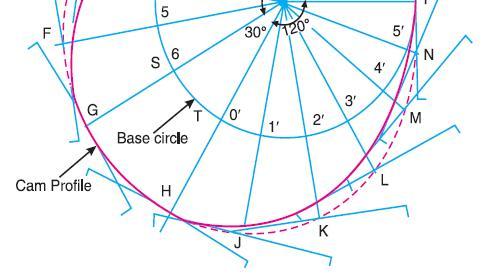
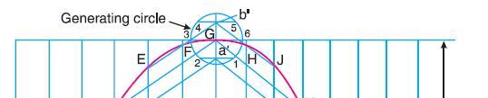
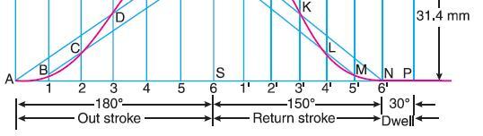
70 Example (Khurmi) Draw the profile of the cam when the roller follower moves with cycloidal motion during out stroke and return stroke, as given below : 1. Out stroke with maximum displacement of 31.4 mm during 180 of cam rotation, 2. Return stroke for the next 150 of cam rotation, 3. Dwell for the remaining 30 of cam rotation. The minimum radius of the cam is 15 mm and the roller diameter of the follower is 10 mm. The axis of the roller follower is offset by 10 mm towards right from the axis of cam shaft.
71
72
73 GEARS
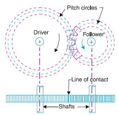
74 Gears Gears are used to tansmit motion from one shaft to another or between a shaft and a slide. This is accomplished by successively engaging teeth. Gears use no intermediate link or connector and transmit motion by direct contact. The surfaces of two bodies make a tangential contact.
75 Advantages and Disadvantages of Gear Drive Advantages 1. It transmits exact velocity ratio. 2. It may be used to transmit large power. 3. It has high efficiency. 4. It has reliable service. 5. It has compact layout. Disadvantages 1. The manufacture of gears require special tools and equipment. 2. The error in cutting teeth may cause vibrations and noise during operation.
76 Classification of Gears 1. According to the position of axes of the shafts. The axes of the two shafts between which the motion is to be transmitted, may be (a) Parallel, (b) Intersecting, and (c) Non-intersecting and non-parallel.
77 a)
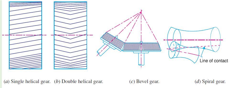
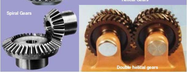
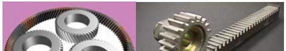
78 Classification of Gears Spur gears: these gears have teeth parallel to the axis of the wheel. Helical gears: in which the teeth are inclined to the axis. The single and double helical gears connecting parallel shafts are shown on previous slide. The double helical gears are known as herringbone gears. A pair of spur gears are kinematically equivalent to a pair of cylindrical discs, keyed to parallel shafts and having a line contact.

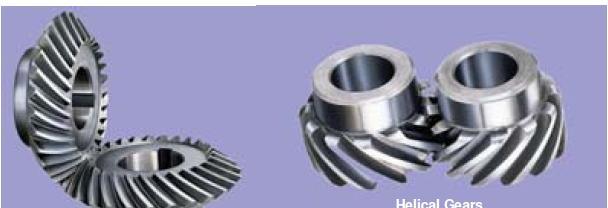
79 Classification of Gears Bevel gears : Gears connecting two non-parallel or intersecting, but coplanar shafts connected by gears. The bevel gears, like spur gears, may also have their teeth inclined to the face of the bevel, in which case they are known as helical bevel gears.

80 Classification of Gears Skew bevel gears or spiral gears :The two nonintersecting and non-parallel i.e. non-coplanar shaft connected by gears. The arrangement is known as skew bevel gearing or spiral gearing. This type of gearing also have a line contact, the rotation of which about the axes generates the two pitch surfaces known as hyperboloids.
81
82 Classification of Gears 2. According to the peripheral velocity of the gears. (a) Low velocity: having velocity less than 3 m/s (b) Medium velocity: gears having velocity between 3 and 15 m/s (c) High velocity: velocity of gears is more than 15 m/s
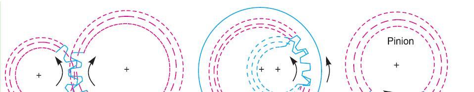
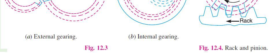
83 Classification of Gears 3. According to the type of gearing. The gears, according to the type of gearing may be classified as : (a) External gearing, (b) Internal gearing, and (c) Rack and pinion. In external gearing, the gears of the two shafts mesh externally with each other. The larger of these two wheels is called spur wheel and the smaller wheel is called pinion. In an external gearing, the motion of the two wheels is always unlike.
84

85
86 4. According to position of teeth on the gear surface. The teeth on the gear surface may be (a) straight, (b) inclined, and (c) curved.
87 In internal gearing, the gears of the two shafts mesh internally with each other. The larger of these two wheels is called annular wheel and the smaller wheel is called pinion. In an internal gearing, the motion of the two wheels is always like. Sometimes, the gear of a shaft meshes externally and internally with the gears in a straight line. Such type of gear is called rack and pinion. The straight line gear is called rack and the circular wheel is called pinion. A little consideration will show that with the help of a rack and pinion, we can convert linear motion into rotary motion and vice-versa.

88 Terms Used in Gears
89 Terms Used in Gears 1. Pitch circle. It is an imaginary circle which by pure rolling action, would give the same motion as the actual gear. 2. Pitch circle diameter. It is the diameter of the pitch circle. The size of the gear is usually specified by the pitch circle diameter. It is also known as pitch diameter. 3. Pitch point. It is a common point of contact between two pitch circles. 4. Pitch surface. It is the surface of the rolling discs which the meshing gears have replaced at the pitch circle. 5. Pressure angle or angle of obliquity. It is the angle between the common normal to two gear teeth at the point of contact and the common tangent at the pitch point. It is usually denoted by φ. The standard pressure angles are 14.5 and 20.
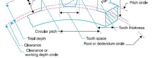
90 Terms Used in Gears 6. Addendum. It is the radial distance of a tooth from the pitch circle to the top of the tooth. 7. Dedendum. It is the radial distance of a tooth from the pitch circle to the bottom of the tooth. 8. Addendum circle. It is the circle drawn through the top of the teeth and is concentric with the pitch circle. 9. Dedendum circle. It is the circle drawn through the bottom of the teeth. It is also called root circle. Note : Root circle diameter = Pitch circle diameter cosφ, φ where is the pressure angle. 10. Circular pitch. It is the distance measured on the circumference of the pitch circle from a point of one tooth to the corresponding point on the next tooth. It is usually denoted by pc.
91 Terms Used in Gears The two gears will mesh together correctly, if the two wheels have the same circular pitch. Note : If D1 and D2 are the diameters of the two meshing gears having the teeth T1 and T2 respectively, then for them to mesh correctly,
92 Terms Used in Gears 12. Module. It is the ratio of the pitch circle diameter in millimeters to the number of teeth. It is usually denoted by m. Mathematically, Module, m = D /T 13. Clearance. It is the radial distance from the top of the tooth to the bottom of the tooth, in a meshing gear. A circle passing through the top of the meshing gear is known as clearance circle. 14. Total depth. It is the radial distance between the addendum and the dedendum circles of a gear. It is equal to the sum of the addendum and dedendum. 15. Working depth. It is the radial distance from the addendum circle to the clearance circle. It is equal to the sum of the addendum of the two meshing gears.
93 Terms Used in Gears 16. Tooth thickness. It is the width of the tooth measured along the pitch circle. 17. Tooth space. It is the width of space between the two adjacent teeth measured along the pitch circle. 18. Backlash. It is the difference between the tooth space and the tooth thickness, as measured along the pitch circle. Theoretically, the backlash should be zero, but in actual practice some backlash must be allowed to prevent jamming of the teeth due to tooth errors and thermal expansion. 19. Face of tooth. It is the surface of the gear tooth above the pitch surface.
94 Terms Used in Gears 20. Flank of tooth. It is the surface of the gear tooth below the pitch surface. 21. Top land. It is the surface of the top of the tooth. 22. Face width. It is the width of the gear tooth measured parallel to its axis. 23. Profile. It is the curve formed by the face and flank of the tooth. 24. Fillet radius. It is the radius that connects the root circle to the profile of the tooth.
95 Terms Used in Gears 25. Path of contact. It is the path traced by the point of contact of two teeth from the beginning to the end of engagement. 26. Length of the path of contact. It is the length of the common normal cut-off by the addendum circles of the wheel and pinion. 27. Arc of contact. It is the path traced by a point on the pitch circle from the beginning to the end of engagement of a given pair of teeth. The arc of contact consists of two parts, i.e. (a) Arc of approach. It is the portion of the path of contact from the beginning of the engagement to the pitch point. (b) Arc of recess. It is the portion of the path of contact from the pitch point to the end of the engagement of a pair of teeth.


96 Law of Gearing Let v1 and v2 be the velocities of the point Q on the wheels1 and 2 respectively. If the teeth are to remain in contact, then the components of these velocities along the common normal MN must be equal.

97 Law of Gearing
98 Law of Gearing Thus we see that the angular velocity ratio is inversely proportional to the ratio of the distances of the point P from the centres O1 and O2, or the common normal to the two surfaces at the point of contact Q intersects the line of centres at point P which divides the centre distance inversely as the ratio of angular velocities. Therefore in order to have a constant angular velocity ratio for all positions of the wheels, the point P must be the fixed point (called pitch point) for the two wheels. In other words, the common normal at the point of contact between a pair of teeth must always pass through the pitch point. This is the fundamental condition which must be satisfied while designing the profiles for the teeth of gear wheels. It is also known as law of gearing.
99 Velocity of Sliding of Teeth The velocity of sliding is the velocity of one tooth relative to its mating tooth along the common tangent at the point of contact. The velocity of point Q, considered as a point on wheel 1, along the common tangent TT is represented by EC. From similar triangles QEC and O1MQ,

100 Similarly, the velocity of point Q, considered as a point on wheel 2, along the common tangent TT is represented by ED. From similar triangles QCD and O2NQ, The velocity of sliding is proportional to the distance of the point of contact from the pitch point.
101 Forms of Teeth 1. Cycloidal teeth 2. Involute teeth
102 Cycloidal Teeth A cycloid is the curve traced by a point on the circumference of a circle which rolls without slipping on a fixed straight line. When a circle rolls without slipping on the outside of a fixed circle, the curve traced by a point on the circumference of a circle is known as epi-cycloid. On the other hand, if a circle rolls without slipping on the inside of a fixed circle, then the curve traced by a point on the circumference of a circle is called hypo-cycloid.
103

104 Involute Teeth An involute of a circle is a plane curve generated by a point on a tangent, which rolls on the circle without slipping or by a point on a taut string which in unwrapped from a reel. In connection with toothed wheels, the circle is known as base circle. The normal at any point of an involute is a tangent to the circle
105 Involute Teeth Base Circle Pitch Circle
 makes with the common tangent to the pitch circles.")
106 where is the pressure angle or the angle of obliquity. It is the angle which the common normal to the base circles (i.e. MN) makes with the common tangent to the pitch circles. If F is the maximum tooth pressure
107 Numerical 1 Example A single reduction gear of 120 kw with a pinion 250 mm pitch circle diameter and speed 650 r.p.m. is supported in bearings on either side. Calculate the total load due to the power transmitted, the pressure angle being 20.
108 Comparison Between Involute and Cycloidal Gears Advantages of involute gears 1. The centre distance for a pair of involute gears can be varied within limits without changing the velocity ratio. This is not true for cycloidal gears which requires exact centre distance to be maintained. 2. In involute gears, the pressure angle, from the start of the engagement of teeth to the end of the engagement, remains constant. But in cycloidal gears, the pressure angle is maximum at the beginning of engagement, reduces to zero at pitch point, starts decreasing and again becomes maximum at the end of engagement. This results in less smooth running of gears. 3. The face and flank of involute teeth are generated by a single curve where as in cycloidal gears, double curves (i.e. epi-cycloid and hypo-cycloid) are required for the face and flank respectively. Thus the involute teeth are easy to manufacture than cycloidal teeth. In involute system, the basic rack has straight teeth and the same can be cut with simple tools.
109 Comparison Between Involute and Cycloidal Gears Advantages of cycloidal gears 1. Since the cycloidal teeth have wider flanks, therefore the cycloidal gears are stronger than the involute gears, for the same pitch. Due to this reason, the cycloidal teeth are preferred specially for cast teeth. 2. In cycloidal gears, the contact takes place between a convex flank and concave surface, whereas in involute gears, the convex surfaces are in contact. This condition results in less wear in cycloidal gears as compared to involute gears. However the difference in wear is negligible. 3. In cycloidal gears, the interference does not occur at all. Though there are advantages of cycloidal gears but they are outweighed by the greater simplicity and flexibility of the involute gears.
110 Systems of Gear Teeth The following four systems of gear teeth are commonly used in practice : Composite system, Full depth involute system, Full depth involute system, and Stub involute system.
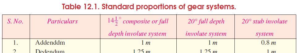
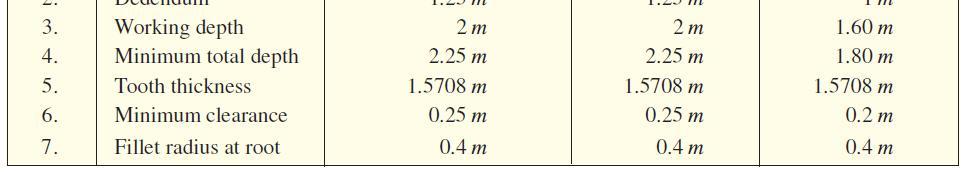
111 Standard Proportions of Gear Systems
112 Length of Path of Contact Where, ra = Radius of addendum circle of pinion, RA = Radius of addendum circle of wheel, r = Radius of pitch circle of pinion, and R =Radius of pitch circle of wheel.
113 Length of Arc of Contact Length of the arc of contact
114 Contact Ratio (or Number of Pairs of Teeth in Contact)
115 Numerical 2 Example The number of teeth on each of the two equal spur gears in mesh are 40. The teeth have 20 involute profile and the module is 6 mm. If the arc of contact is 1.75 times the circular pitch, find the addendum.
116 Numerical 3 Example A pinion having 30 teeth drives a gear having 80 teeth. The profile of the gears is involute with 20 pressure angle, 12 mm module and 10 mm addendum. Find the length of path of contact, arc of contact and the contact ratio.
117 Interchangeable Gears The gears are interchangeable if they are standard ones. The gears are interchangeable if they are: The same module The same pressure angle The same addendums and dedendums, and The same thickness. The tooth system which relates the various parameters of gears such as pressure angle, addendum, dedendum, tooth thickness, working depth etc. to attain interchangeability of the gears of all tooth numbers, but of the same pressure angle and pitch is said to be a standard system.
118 Interference and Undercutting The phenomenon when the tip of tooth undercuts the root on its mating gear is known as interference. Interference may only be prevented, if the addendum circles of the two mating gears cut the common tangent to the base circles between the points of tangency. Base Circle Pitch Circle Addendum Circles

119 Helical Gears A helical gear has teeth in the form of helix around the gear. Two such gears may be used to connect two parallel shafts in place of spur gear.

120 Helical Gears 1. Normal pitch. It is the distance between similar faces of adjacent teeth, along a helix on the pitch cylinder normal to the teeth. It is denoted by pn. 2. Axial pitch. It is the distance measured parallel to the axis, between similar faces of adjacent teeth. It is the same as circular pitch and is therefore denoted by pc. If α is the helix angle, then circular pitch,
12/25/2015. Chapter 20. Cams. Mohammad Suliman Abuhiba, Ph.D., PE
 Chapter 20 Cams 1 2 Introduction A cam: a rotating machine element which gives reciprocating or oscillating motion to another element (follower) Cam & follower have a line constitute a higher pair. of
(POWER TRANSMISSION Methods)
") UNIT-5 (POWER TRANSMISSION Methods) It is a method by which you can transfer cyclic motion from one place to another or one pulley to another pulley. The ways by which we can transfer cyclic motion are:-
UNIT-5 (POWER TRANSMISSION Methods) It is a method by which you can transfer cyclic motion from one place to another or one pulley to another pulley. The ways by which we can transfer cyclic motion are:-
St.MARTIN S ENGINEERING COLLEGE Dhulapally, Secunderabad
 St.MARTIN S ENGINEERING COLLEGE Dhulapally, Secunderabad-500 014 Subject: Kinematics of Machines Class : MECH-II Group A (Short Answer Questions) UNIT-I 1 Define link, kinematic pair. 2 Define mechanism
1. (a) Discuss various types of Kinematic links with examples. (b) Explain different types of constrained motions with examples.
 Discuss various types of Kinematic links with examples. (b) Explain different types of constrained motions with examples.") Code No: RR310304 Set No. 1 III B.Tech I Semester Supplementary Examinations, February 2007 KINEMATICS OF MACHINERY ( Common to Mechanical Engineering, Mechatronics and Production Engineering) Time: 3
Code No: RR310304 Set No. 1 III B.Tech I Semester Supplementary Examinations, February 2007 KINEMATICS OF MACHINERY ( Common to Mechanical Engineering, Mechatronics and Production Engineering) Time: 3
ME6401 KINEMATICS OF MACHINERY UNIT- I (Basics of Mechanism)
") ME6401 KINEMATICS OF MACHINERY UNIT- I (Basics of Mechanism) 1) Define resistant body. 2) Define Link or Element 3) Differentiate Machine and Structure 4) Define Kinematic Pair. 5) Define Kinematic Chain.
ME6401 KINEMATICS OF MACHINERY UNIT- I (Basics of Mechanism) 1) Define resistant body. 2) Define Link or Element 3) Differentiate Machine and Structure 4) Define Kinematic Pair. 5) Define Kinematic Chain.
Code No: R Set No. 1
 Code No: R05310304 Set No. 1 III B.Tech I Semester Regular Examinations, November 2007 KINEMATICS OF MACHINERY ( Common to Mechanical Engineering, Mechatronics, Production Engineering and Automobile Engineering)
KINEMATICS OF MACHINARY UBMC302 QUESTION BANK UNIT-I BASICS OF MECHANISMS PART-A
 KINEMATICS OF MACHINARY UBMC302 QUESTION BANK UNIT-I BASICS OF MECHANISMS PART-A 1. Define the term Kinematic link. 2. Classify kinematic links. 3. What is Mechanism? 4. Define the terms Kinematic pair.
SYED AMMAL ENGINEERING COLLEGE
 SYED AMMAL ENGINEERING COLLEGE (Approved by the AICTE, New Delhi, Govt. of Tamilnadu and Affiliated to Anna University, Chennai) Established in 1998 - An ISO 9001:2000 Certified Institution Dr. E.M.Abdullah
Gear Tooth Geometry - This is determined primarily by pitch, depth and pressure angle
 Gear Tooth Geometry - This is determined primarily by pitch, depth and pressure angle Addendum: The radial distance between the top land and the pitch circle. Addendum Circle: The circle defining the outer
2. a) What is pantograph? What are its uses? b) Prove that the peaucellier mechanism generates a straight-line motion. (5M+10M)
 What is pantograph? What are its uses? b) Prove that the peaucellier mechanism generates a straight-line motion. (5M+10M)") Code No: R22032 R10 SET - 1 1. a) Define the following terms? i) Link ii) Kinematic pair iii) Degrees of freedom b) What are the inversions of double slider crank chain? Describe any two with neat sketches.
Code No: R22032 R10 SET - 1 1. a) Define the following terms? i) Link ii) Kinematic pair iii) Degrees of freedom b) What are the inversions of double slider crank chain? Describe any two with neat sketches.
 DEPARTMENT OF MECHANICAL ENGINEERING ME6401- KINEMATICS OF MACHINERY QUESTION BANK Part-A Unit 1-BASICS OF MECHANISMS 1. Define degrees of freedom. 2. What is meant by spatial mechanism? 3. Classify the
Subject with Code: Kinematic of Machinery (16ME304)Course & Branch: B. Tech - ME Year &Sem : II-B. Tech &I-Sem Regulation: R16
Course & Branch: B. Tech - ME Year &Sem : II-B. Tech &I-Sem Regulation: R16") SIDDHARTH INSTITUTE OF ENGINEERING &TECHNOLOGY:: PUTTUR (Approved by AICTE, New Delhi & Affiliated to JNTUA, Anantapuramu) (Accredited by NBA & Accredited by NAAC with A Grade) (An ISO 9001:2008 Certified
SIDDHARTH INSTITUTE OF ENGINEERING &TECHNOLOGY:: PUTTUR (Approved by AICTE, New Delhi & Affiliated to JNTUA, Anantapuramu) (Accredited by NBA & Accredited by NAAC with A Grade) (An ISO 9001:2008 Certified
 VALLIAMMAI ENGINEERING COLLEGE DEPARTMENT OF MECHANICAL ENGINEERING ME6401- KINEMATICS OF MACHINERY QUESTION BANK PART-A Unit 1-BASICS OF MECHANISMS 1. Define degrees of freedom. BT1 2. Describe spatial
GEAR CONTENTS POWER TRANSMISSION GEAR TYPES OF GEARS NOMENCLATURE APPLICATIONS OF GEARS VELOCITY RATIO GEAR TRAINS EXAMPLE PROBLEMS AND QUESTIONS
 GEAR CONTENTS POWER TRANSMISSION GEAR TYPES OF GEARS NOMENCLATURE APPLICATIONS OF GEARS VELOCITY RATIO GEAR TRAINS EXAMPLE PROBLEMS AND QUESTIONS GEAR.. Power transmission is the movement of energy from
INSTITUTE OF AERONAUTICAL ENGINEERING
 INSTITUTE OF AERONAUTICAL ENGINEERING (Autonomous) Dundigal, Hyderabad -500 043 Course Name Course Code Class Branch MECHANICAL ENGINEERING TUTORIAL QUESTION BANK 2015 2016 : KINEMATICS OF MACHINES : A40309
Lecture (7) on. Gear Measurement. By Dr. Emad M. Saad. Industrial Engineering Dept. Faculty of Engineering. Fayoum University.
 on. Gear Measurement. By Dr. Emad M. Saad. Industrial Engineering Dept. Faculty of Engineering. Fayoum University.") 1 Lecture (7) on Gear Measurement Fayoum University By Dr. Emad M. Saad Industrial Engineering Dept. Faculty of Engineering Fayoum University Faculty of Engineering Industrial Engineering Dept. 2015-2016
1 Lecture (7) on Gear Measurement Fayoum University By Dr. Emad M. Saad Industrial Engineering Dept. Faculty of Engineering Fayoum University Faculty of Engineering Industrial Engineering Dept. 2015-2016
Basic Fundamentals of Gear Drives
 Basic Fundamentals of Gear Drives Course No: M06-031 Credit: 6 PDH A. Bhatia Continuing Education and Development, Inc. 9 Greyridge Farm Court Stony Point, NY 10980 P: (877) 322-5800 F: (877) 322-4774
Code No: R Set No. 1
 Code No: R05222106 Set No. 1 II B.Tech II Semester Supplimentary Examinations, Aug/Sep 2007 MECHANISMS AND MECHANICAL DESIGN (Aeronautical Engineering) Time: 3 hours Max Marks: 80 Answer any FIVE Questions
CHENDU COLLEGE OF ENGINEERING & TECHNOLOGY DEPARTMENT OF MECHANICAL ENGINEERING QUESTION BANK IV SEMESTER
 CHENDU COLLEGE OF ENGINEERING & TECHNOLOGY DEPARTMENT OF MECHANICAL ENGINEERING QUESTION BANK IV SEMESTER Sub Code: ME 6401 KINEMATICS OF MACHINERY UNIT-I PART-A 1. Sketch and define Transmission angle
FIRSTRANKER. 2. (a) Distinguish (by neat sketches) betweenpeaucellier mechanism and Hart mechanism.
 Distinguish (by neat sketches) betweenpeaucellier mechanism and Hart mechanism.") Code No: 07A51404 R07 Set No. 2 IIIB.Tech I Semester Examinations,May 2011 KINEMATICS OF MACHINERY Mechatronics Time: 3 hours Max Marks: 80 Answer any FIVE Questions All Questions carry equal marks 1.
Code No: 07A51404 R07 Set No. 2 IIIB.Tech I Semester Examinations,May 2011 KINEMATICS OF MACHINERY Mechatronics Time: 3 hours Max Marks: 80 Answer any FIVE Questions All Questions carry equal marks 1.
UNIT -I. Ans: They are specified by the no. of strands & the no. of wires in each strand.
 VETRI VINAYAHA COLLEGE OF ENGINEERING AND TECHNOLOGY, THOTTIAM, NAMAKKAL-621215. DEPARTMENT OF MECHANICAL ENGINEERING SIXTH SEMESTER / III YEAR ME6601 DESIGN OF TRANSMISSION SYSTEM (Regulation-2013) UNIT
Metrology Prof. Dr Kanakuppi Sadashivappa Bapuji Institute of Engineering and Technology Davangere. Lecture 25 Introduction of Gears
 Metrology Prof. Dr Kanakuppi Sadashivappa Bapuji Institute of Engineering and Technology Davangere Lecture 25 Introduction of Gears I welcome you for the series of lecture on gear measurement and at module
ME6601 DESIGN OF TRANSMISSION SYSTEMS
 SYED AMMAL ENGINEERING COLLEGE (Approved by the AICTE, New Delhi, Govt. of Tamilnadu and Affiliated to Anna University, Chennai) Established in 1998 - An ISO 9001:2008 Certified Institution Dr. E.M.Abdullah
CH#13 Gears-General. Drive and Driven Gears 3/13/2018
 CH#13 Gears-General A toothed wheel that engages another toothed mechanism in order to change the speed or direction of transmitted motion The gear set transmits rotary motion and force. Gears are used
Catalog Q Conversion For those wishing to ease themselves into working with metric gears
 1.3.4 Conversion For those wishing to ease themselves into working with metric gears by looking at them in terms of familiar inch gearing relationships and mathematics, Table 1-5 is offered as a means
Theory of Machines. CH-1: Fundamentals and type of Mechanisms
 CH-1: Fundamentals and type of Mechanisms 1. Define kinematic link and kinematic chain. 2. Enlist the types of constrained motion. Draw a label sketch of any one. 3. Define (1) Mechanism (2) Inversion
Introduction. Kinematics and Dynamics of Machines. Involute profile. 7. Gears
 Introduction The kinematic function of gears is to transfer rotational motion from one shaft to another Kinematics and Dynamics of Machines 7. Gears Since these shafts may be parallel, perpendicular, or
INSTITUTE OF AERONAUTICAL ENGINEERING
 Name Code Class Branch INSTITUTE OF AERONAUTICAL ENGINEERING Dundigal, Hyderabad -500 043 MECHANICAL ENGINEERING QUESTION BANK : KINEMATICS OF MACHINERY : A40309 : II B. Tech II Semester : Mechanical Engineering
1/2/2015 2:04 PM. Chapter 13. Gears General. Dr. Mohammad Suliman Abuhaiba, PE
 Chapter 13 Gears General 1 2 Chapter Outline 1. Types of Gears 2. Nomenclature 3. Conjugate Action 4. Involute Properties 5. Fundamentals 6. Contact Ratio 7. Interference 8. The Forming of Gear Teeth 9.
12/6/2013 9:09 PM. Chapter 13. Gears General. Dr. Mohammad Suliman Abuhaiba, PE
 Chapter 13 Gears General 1 2 Chapter Outline 1. Types of Gears 2. Nomenclature 3. Conjugate Action 4. Involute Properties 5. Fundamentals 6. Contact Ratio 7. Interference 8. The Forming of Gear Teeth 9.
Part VII: Gear Systems: Analysis
 Part VII: Gear Systems: Analysis This section will review standard gear systems and will provide the basic tools to perform analysis on these systems. The areas covered in this section are: 1) Gears 101:
11. GEAR TRANSMISSIONS
 11. GEAR TRANSMISSIONS 11.1. GENERAL CONSIDERATIONS Gears are one of the most important elements used in machinery. There are few mechanical devices that do not have the need to transmit power and motion
BRCM COLLEGE OF ENGINEERING & TECHNOLOGY BAHAL, BHIWANI Practical Experiment Instructions Sheet
 BRCM COLLEGE OF KOM ME- 212 F KINEMATICS OF MACHINES LAB BRANCH-ME List of Experiments : 1. To study various types of Kinematic links, pairs, chains and Mechanisms. 2. To study inversions of 4 Bar Mechanisms,
BHARATHIDASAN ENGINEERING COLLEGE DEPARTMENT OF MECHANICAL ENGINEERING ME6401- KINEMATICS OF MACHINERY QUESTION BANK
 1 BHARATHIDASAN ENGINEERING COLLEGE DEPARTMENT OF MECHANICAL ENGINEERING ME6401- KINEMATICS OF MACHINERY QUESTION BANK Unit 1-BASICS OF MECHANISMS PART-A 1) Differentiate between a machine and a structure?
 Lecture plan UNIT I Basics of Mechanisms SYLLABUS Introduction: Definitions : Link or Element, Pairing of Elements with degrees of freedom, Grubler s criterion (without derivation), Kinematic chain, Mechanism,
FIRSTRANKER. Code No: R R09 Set No. 2
 Code No: R09220302 R09 Set No. 2 IIB.Tech IISemester Examinations,APRIL 2011 KINEMATICS OF MACHINERY Common to Mechanical Engineering, Mechatronics, Production Engineering, Automobile Engineering Time:
Gear Measurement. Lecture (7) Mechanical Measurements
 Mechanical Measurements") 18 3. Gear profile checking 2. Involute measuring machine In this method the gear is held on a mandrel and circular disc of same diameter as the base circle of gear for the measurement is fixed on the
18 3. Gear profile checking 2. Involute measuring machine In this method the gear is held on a mandrel and circular disc of same diameter as the base circle of gear for the measurement is fixed on the
 DEPARTMENT OF MECHANICAL ENGINEERING Subject code: ME6601 Subject Name: DESIGN OF TRANSMISSION SYSTEMS UNIT-I DESIGN OF TRANSMISSION SYSTEMS FOR FLEXIBLE ELEMENTS 1. What is the effect of centre distance
KINGS COLLEGE OF ENGINEERING DEPARTMENT OF MECHANICAL ENGINEERING
 KINGS COLLEGE OF ENGINEERING DEPARTMENT OF MECHANICAL ENGINEERING QUESTION BANK Sub Code/Name: ME 1352 DESIGN OF TRANSMISSION SYSTEMS Year/Sem: III / VI UNIT-I (Design of transmission systems for flexible
Machines and mechanisms
 Machines and mechanisms Contents: 1. Basics and Kinematics of Mechanism 2. Cam and Follower 3. Governor 4. Gear and Gear Train 5. Inertia Force Analysis Basics and Kinematics Mechanism: 1. A rigid body
SECTION 4 SPUR GEAR CALCULATIONS
 Function of α, or invα, is known as involute function. Involute function is very important in gear design. Involute function values can be obtained from appropriate tables. With the 3.1 Contact Ratio center
Chapter 8 Kinematics of Gears
 Chapter 8 Kinematics of Gears Gears! Gears are most often used in transmissions to convert an electric motor s high speed and low torque to a shaft s requirements for low speed high torque: Speed is easy
Bevel Gears n A Textbook of Machine Design
 080 n A Textbook of Machine Design C H A P T E R 30 Bevel Gears. Introduction.. Classification of Bevel Gears. 3. Terms used in Bevel Gears. 4. Determination of Pitch Angle for Bevel Gears. 5. Proportions
Unit IV GEARS. Gallery
 Gallery Components of a typical, four stroke cycle, DOHC piston engine. (E) Exhaust camshaft, (I) Intake camshaft, (S) Spark plug, (V) Valves, (P) Piston, (R) Connecting rod, (C) Crankshaft, (W) Water
1.6 Features of common gears
 1.6 Features of common gears Chapter 1.2 covered briefly on types of gear. The main gear features are explained here. Helical gear Helical gear has characteristics of transferability of larger load, less
Chapter seven. Gears. Laith Batarseh
 Chapter seven Gears Laith Batarseh Gears are very important in power transmission between a drive rotor and driven rotor What are the functions of gears? - Transmit motion and torque (power) between shafts
Effect of Geometry Factor I & J Factor Multipliers in the performance of Helical Gears
 Effect of Geometry Factor I & J Factor Multipliers in the performance of Helical Gears 1 Amit D. Modi, 2 Manan B. Raval, 1 Lecturer, 2 Lecturer, 1 Department of Mechanical Engineering, 2 Department of
TECHNOLOGY MECHANISMS
 TECHNOLOGY MECHANISMS 3º ESO IES CHAN DO MONTE URTAZA 1 WHAT IS A MECHANISM? Mechanism are devices that have been designed to make jobs easier. They all have certain things in common: They involve some
What are the functions of gears? What is gear?
 8//0 hapter seven Laith atarseh are very important in power transmission between a drive rotor and driven rotor What are the functions of gears? - Transmit motion and torque (power) between shafts - Maintain
Chapter 3. Transmission Components
 Chapter 3. Transmission Components The difference between machine design and structure design An important design problem in a mechanical system is how to transmit and convert power to achieve required
Moments. It doesn t fall because of the presence of a counter balance weight on the right-hand side. The boom is therefore balanced.
 Moments The crane in the image below looks unstable, as though it should topple over. There appears to be too much of the boom on the left-hand side of the tower. It doesn t fall because of the presence
SECTION 8 BEVEL GEARING
 SECTION 8 BEVEL GEARING For intersecting shafts, bevel gears offer a good means of transmitting motion and power. Most transmissions occur at right angles, Figure 8-1, but the shaft angle can be any value.
Engineering Information
 Engineering nformation Gear Nomenclature ADDENDUM (a) is the height by which a tooth projects beyond the pitch circle or pitch line. BASE DAMETER (D b ) is the diameter of the base cylinder from which
INVOLUTE SPIRAL FACE COUPLINGS AND GEARS: DESIGN APPROACH AND MANUFACTURING TECHNIQUE
 УДК 621.9.015 Dr. Alexander L. Kapelevich, Stephen D. Korosec 38 INVOLUTE SPIRAL FACE COUPLINGS AND GEARS: DESIGN APPROACH AND MANUFACTURING TECHNIQUE This paper presents spiral face gears with an involute
Different types of gears. Spur gears. Idler gears. Worm gears. Bevel gears. Belts & Pulleys
 GEARS Robot Gears By using different gear diameters, you can exchange between rotational (or translation) velocity and torque. by looking at the motor datasheet you can determine the output velocity and
1.8 Rack shift of the gear
 1.8 Rack shift of the gear Undercut When Number of teeth is belo minimum as shon in Fig. 3, part of dedendum is no longer an Involute curve but ill look like a shape scooped out by cutter tool. Refer to
CHAPTER 5 PREVENTION OF TOOTH DAMAGE IN HELICAL GEAR BY PROFILE MODIFICATION
 90 CHAPTER 5 PREVENTION OF TOOTH DAMAGE IN HELICAL GEAR BY PROFILE MODIFICATION 5.1 INTRODUCTION In any gear drive the absolute and the relative transmission error variations normally increases with an
Hours / 100 Marks Seat No.
 17412 16117 3 Hours / 100 Seat No. Instructions (1) All Questions are Compulsory. (2) Answer each next main Question on a new page. (3) Illustrate your answers with neat sketches wherever necessary. (4)
Chain Drives. Pitch. Basic Types -There are six major types of power-
 1 2 Power transmission chains have two things in common; side bars or link plates, and pin and bushing joints. The chain articulates at each joint to operate around a toothed sprocket. The pitch of the
All levers are one of three types, usually called classes. The class of a lever depends on the relative position of the load, effort and fulcrum:
 Página 66 de 232 Mechanisms A mechanism is simply a device which takes an input motion and force, and outputs a different motion and force. The point of a mechanism is to make the job easier to do. The
Program Internal Gear Set Profile Shift Coefficients With Zero Backlash Introduction
 Program 60-107 Internal Gear Set Profile Shift Coefficients With Zero Backlash Introduction The purpose of this model is to provide data for a gear set when the tooth thickness and/or the center distance
'' ''' '' ''' Code No: R R16 SET - 1
 Code No: R161232 R16 SET - 1 1. a) List the Primary requirements of a Steam Boiler. (2M) b) What are the distinguishing features between a Casting and a Pattern? (2M) c) Define (i) Brake Power; (ii) Indicated
Chapter 10 Machine elements. Bachelor Program in AUTOMATION ENGINEERING Prof. Rong-yong Zhao Second Semester,
 Chapter 10 Machine elements Bachelor Program in AUTOMATION ENGINEERING Prof. Rong-yong Zhao (zhaorongyong@tongji.edu.cn) Second Semester,2013-2014 Content 10.1 Cams 10.1.1- Synthesis of the mechanism 10.1.2-
DHANALAKSHMI COLLEGE OF ENGINEERING
 DHANALAKSHMI COLLEGE OF ENGINEERING (Dr.VPR Nagar, Manimangalam, Tambaram) Chennai - 601 301 DEPARTMENT OF MECHANICAL ENGINEERING III YEAR MECHANICAL - VI SEMESTER ME 6601 DESIGN OF TRANSMISSION SYSTEMS
Gear Engineering Data. Spur Gear Gear Formulas Drive Selection Horsepower and Torque Tables
 Engineering Gear Engineering Data Spur Gear Gear Formulas Drive Selection Horsepower and Torque Tables G-79 Gear Selection Stock Spur Gear Drive Selection When designing a stock gear drive using the horsepower
Finite element analysis of profile modified spur gear
 Finite element analysis of profile modified spur gear Sagar Gaur Mechanical Engineering Department, Institute of Technology, YashluvVirwani Mechanical Engineering Department, Institute of Technology, Rudresh
Gearheads H-51. Gearheads for AC Motors H-51
 Technical Reference H-51 for AC Since AC motor gearheads are used continuously, primarily for transmitting power, they are designed with priority on ensuring high permissible torque, long life, noise reduction
Driver Driven. InputSpeed. Gears
 Gears Gears are toothed wheels designed to transmit rotary motion and power from one part of a mechanism to another. They are fitted to shafts with special devices called keys (or splines) that ensure
MECHANICAL DRIVES 1 SPUR GEAR DRIVES LEARNING ACTIVITY PACKET BB502-XD06AEN
 MECHANICAL DRIVES 1 LEARNING ACTIVITY PACKET SPUR GEAR DRIVES BB502-XD06AEN LEARNING ACTIVITY PACKET 6 SPUR GEAR DRIVES INTRODUCTION This LAP will begin the study of the third type of adjacent shaft-to-shaft
1 135 teeth to rack
 1. A spur gear with 46 teeth, 2.5 module has to be cut on a column and knee type horizontal milling machine with a rotary disc type form gear milling cutter. The 2.5 module cutter no. 3 is used on a blank
T25 T25 T25 T27 T27 T28 T28 T28 T28 T29 T29 T29 T31 T37 T37 T38 T T T48
 1.0 INTRODUCTION 2.0 BASIC GEOMETRY OF SPUR GEARS 2.1 Basic Spur Gear Geometry 2.2 The Law of Gearing 2.3 The Involute Curve 2.4 Pitch Circles 2.5 Pitch 2.5.1 Circular Pitch 2.5.2 Diametral Pitch 2.5.3
CHAPTER 6 GEARS CHAPTER LEARNING OBJECTIVES
 CHAPTER 6 GEARS CHAPTER LEARNING OBJECTIVES Upon completion of this chapter, you should be able to do the following: Compare the types of gears and their advantages. Did you ever take a clock apart to
LECTURE NOTES ENT348 MECHANICAL SYSTEM DESIGN Lecture 6 25/3/2015 CAM DESIGN
 LECTURE NOTES ENT348 MECHANICAL SYSTEM DESIGN Lecture 6 25/3/2015 CAM DESIGN Dr. HAFTIRMAN MECHANICAL ENGINEEERING PROGRAM SCHOOL OF MECHATRONIC ENGINEERING UniMAP COPYRIGHT RESERVED 2015 ENT348 Mechanical
Lecture 13 BEVEL GEARS
 Lecture 13 BEVEL GEARS CONTENTS 1. Bevel gear geometry and terminology 2. Bevel gear force analysis 3. Bending stress analysis 4. Contact stress analysis 5. Permissible bending fatigue stress 6. Permissible
Simple Gears and Transmission
 Simple Gears and Transmission Contents How can transmissions be designed so that they provide the force, speed and direction required and how efficient will the design be? Initial Problem Statement 2 Narrative
INTRODUCTION: Rotary pumps are positive displacement pumps. The rate of flow (discharge) of rotary pump remains constant irrespective of the
 of rotary pump remains constant irrespective of the") INTRODUCTION: Rotary pumps are positive displacement pumps. The rate of flow (discharge) of rotary pump remains constant irrespective of the pressure. That is, even at very high pressure, these pumps can
INTRODUCTION: Rotary pumps are positive displacement pumps. The rate of flow (discharge) of rotary pump remains constant irrespective of the pressure. That is, even at very high pressure, these pumps can
Bibliography. [1] Buckingham, Earle: "Analytical Mechanics of Gears", McGraw-Hill, New York, 1949, and republished by Dover, New York, 1963.
![Bibliography. [1] Buckingham, Earle: Analytical Mechanics of Gears, McGraw-Hill, New York, 1949, and republished by Dover, New York, 1963.](/thumbs/87/96820687.jpg "Bibliography. [1] Buckingham, Earle: Analytical Mechanics of Gears, McGraw-Hill, New York, 1949, and republished by Dover, New York, 1963.") Bibliography The first five references listed are books on gearing. Some of them deal not only with the geometry, but also with many other aspects of gearing. However, the books are included in this bibliography
Bibliography The first five references listed are books on gearing. Some of them deal not only with the geometry, but also with many other aspects of gearing. However, the books are included in this bibliography
11/23/2013. Chapter 13. Gear Trains. Dr. Mohammad Suliman Abuhiba, PE
 Chapter 13 Gear Trains 1 2 13.2. Types of Gear Trains 1. Simple gear train 2. Compound gear train 3. Reverted gear train 4. Epicyclic gear train: axes of shafts on which the gears are mounted may move
Bevel Gears. Fig.(1) Bevel gears
 Bevel gears") Bevel Gears Bevel gears are cut on conical blanks to be used to transmit motion between intersecting shafts. The simplest bevel gear type is the straighttooth bevel gear or straight bevel gear as can be
Bevel Gears Bevel gears are cut on conical blanks to be used to transmit motion between intersecting shafts. The simplest bevel gear type is the straighttooth bevel gear or straight bevel gear as can be
Spur Gears. Helical Gears. Bevel Gears. Worm Gears
 Spur s General: Spur gears are the most commonly used gear type. They are characterized by teeth which are perpendicular to the face of the gear. Spur gears are by far the most commonly available, and
III B.Tech I Semester Supplementary Examinations, May/June
 Set No. 1 III B.Tech I Semester Supplementary Examinations, May/June - 2015 1 a) Derive the expression for Gyroscopic Couple? b) A disc with radius of gyration of 60mm and a mass of 4kg is mounted centrally
PC CAM (PLATE + CYLINDRICAL CAM) DESIGN SAIFUL IRWAN BIN SARKAWI. A project report is submitted in partial
 DESIGN SAIFUL IRWAN BIN SARKAWI. A project report is submitted in partial") ii PC CAM (PLATE + CYLINDRICAL CAM) DESIGN SAIFUL IRWAN BIN SARKAWI A project report is submitted in partial fulfillment of the requirement for the award of the Degree of Master of Mechanical Engineering
ii PC CAM (PLATE + CYLINDRICAL CAM) DESIGN SAIFUL IRWAN BIN SARKAWI A project report is submitted in partial fulfillment of the requirement for the award of the Degree of Master of Mechanical Engineering
Design and Analysis of Six Speed Gear Box
 Design and Analysis of Six Speed Gear Box Ujjayan Majumdar 1, Sujit Maity 2, Gora Chand Chell 3 1,2 Student, Department of Mechanical Engineering, Jalpaiguri Government Engineering College, Jalpaiguri,
Simple Gears and Transmission
 Simple Gears and Transmission Simple Gears and Transmission page: of 4 How can transmissions be designed so that they provide the force, speed and direction required and how efficient will the design be?
428 l Theory of Machines
 428 l heory of Machines 13 Fea eatur tures es 1. Introduction. 2. ypes of Gear rains. 3. Simple Gear rain. 4. ompound Gear rain. 5. Design of Spur Gears. 6. Reverted Gear rain. 7. picyclic Gear rain. 8.
CHENDU COLLEGE OF ENGINEERING & TECHNOLOGY DEPARTMENT OF MECHANICAL ENGINEERING QUESTION BANK
 CHENDU COLLEGE OF ENGINEERING & TECHNOLOGY DEPARTMENT OF MECHANICAL ENGINEERING QUESTION BANK Sub Code: ME 2342 DESIGN OF TRANSMISSION SYSTEM UNIT - I 1. How the bevel gears are classified? Explain with
we will learn how to conduct force and torque analysis on gears in order to calculate bearing
 8.1 Introduction to Gears Gears are used to transmit motion and torque from one shaft to another. In this section we will discuss the kinematics of gears; that is, the motion relationships between gears.
A comparison of the gear calculation process according to Swedish and American textbooks for higher education
 World Transactions on Engineering and Technology Education Vol.6, No.1, 2007 2007 UICEE A comparison of the gear calculation process according to Swedish and American textbooks for higher education Samir
10/29/2013. Chapter 9. Mechanisms with Lower Pairs. Dr. Mohammad Abuhiba, PE
 Chapter 9 Mechanisms with Lower Pairs 1 2 9.1. Introduction When the two elements of a pair have a surface contact and a relative motion takes place, the surface of one element slides over the surface
Copyright Notice. Small Motor, Gearmotor and Control Handbook Copyright Bodine Electric Company. All rights reserved.
 Copyright Notice Small Motor, Gearmotor and Control Handbook Copyright 1993-2003 Bodine Electric Company. All rights reserved. Unauthorized duplication, distribution, or modification of this publication,
ISO INTERNATIONAL STANDARD. Bevel and hypoid gear geometry. Géométrie des engrenages coniques et hypoïdes. First edition
 INTERNATIONAL STANDARD ISO 23509 First edition 2006-09-01 Bevel and hypoid gear geometry Géométrie des engrenages coniques et hypoïdes Reference number ISO 2006 Provläsningsexemplar / Preview PDF disclaimer
F-39. Technical Reference
 Gearheads Role of the Gearhead The role of a gearhead is closely related to motor development. Originally, when the AC motor was a simple rotating device, the gearhead was mainly used to change the motor
ANALYSIS OF STRESSES AND DEFLECTIONS IN SPUR GEAR
 International Journal of Mechanical Engineering and Technology (IJMET) Volume 8, Issue 4, April 2017, pp. 461 473 Article ID: IJMET_08_04_050 Available online at http://www.iaeme.com/ijmet/issues.asp?jtype=ijmet&vtype=8&itype=4
CLASSIFICATION OF ROLLING-ELEMENT BEARINGS
 CLASSIFICATION OF ROLLING-ELEMENT BEARINGS Ball bearings can operate at higher speed in comparison to roller bearings because they have lower friction. In particular, the balls have less viscous resistance
1.7 Backlash. Summary of the backlash is play or clearance between one pair of gear. Fig. 17 Backlash
 1.7 Backlash Summary of the backlash is play or clearance between one pair of gear. Fig. 17 Backlash Great care is taken to produce the gear with zero deviation. However we are unable to completely eliminate
Theory of Mechanisms and Machines
 Theory of Mechanisms and Machines Theory of Mechanisms and Machines C.S. SHARMA Formerly Professor Department of Mechanical Engineering Jai Narain Vyas University Jodhpur KAMLESH PUROHIT Professor Department
The Geometry of Involute Gears
 The Geometry of Involute Gears J.R. Colbourne The Geometry of Involute Gears With 217 Illustrations Springer-Verlag New York Berlin Heidelberg London Paris Tokyo J.R. Colbourne Department of Mechanical
Dynamics of Machines. Prof. Amitabha Ghosh. Department of Mechanical Engineering. Indian Institute of Technology, Kanpur. Module No.
 Dynamics of Machines Prof. Amitabha Ghosh Department of Mechanical Engineering Indian Institute of Technology, Kanpur Module No. # 05 Lecture No. # 01 V & Radial Engine Balancing In the last session, you
ANALYSIS OF GEAR QUALITY CRITERIA AND PERFORMANCE OF CURVED FACE WIDTH SPUR GEARS
 8 FASCICLE VIII, 8 (XIV), ISSN 11-459 Paper presented at Bucharest, Romania ANALYSIS OF GEAR QUALITY CRITERIA AND PERFORMANCE OF CURVED FACE WIDTH SPUR GEARS Laurentia ANDREI 1), Gabriel ANDREI 1) T, Douglas
MODULE- 5 : INTRODUCTION TO HYDROSTATIC UNITS (PUMPS AND MOTORS)
") MODULE- 5 : INTRODUCTION TO HYDROSTATIC UNITS (PUMPS AND MOTORS) LECTURE- 18 : BASIC FEATURES OF SOME Hydraulic Pumps & Motors Introduction In this section we shall discuss the working principles and fundamental
MODULE- 5 : INTRODUCTION TO HYDROSTATIC UNITS (PUMPS AND MOTORS) LECTURE- 18 : BASIC FEATURES OF SOME Hydraulic Pumps & Motors Introduction In this section we shall discuss the working principles and fundamental