Chapter 8 Kinematics of Gears
|
|
|
- Erika Garrison
- 5 years ago
- Views:
Transcription

1 Chapter 8 Kinematics of Gears

2 Gears! Gears are most often used in transmissions to convert an electric motor s high speed and low torque to a shaft s requirements for low speed high torque: Speed is easy to generate, because voltage is easy to generate Torque is difficult to generate because it requires large amounts of current Gears essentially allow positive engagement between teeth so high forces can be transmitted while still undergoing essentially rolling contact Gears do not depend on friction and do best when friction is minimized Basic Law of Gearing: A common normal (the line of action) to the tooth profiles at their point of contact must, in all positions of the contacting teeth, pass through a fixed point on the line-of-centers called the pitch point Any two curves or profiles engaging each other and satisfying the law of gearing are conjugate curves, and the relative rotation speed of the gears will be constant

3 Spur Gears Teeth are parallel to the axis of the gear Advantages Cost Ease of manufacture Availability Disadvantages Only works with mating gear Axis of each gear must be parallel

4 Standard Spur Gears (Berg Master Catalog)

5 Helical Gears Teeth are at an angle to the gear axis (usually 10 to 45 ) called helix angle Advantages Smooth and quiet due to gradual tooth engagements (spur gears whine at high speed due to impact). Helical gears good up to speeds in excess of 5,000 ft/min More tooth engagement allows for greater power transmission for given gear size. Parallel to perpendicular shaft arrangement Fig 8.2 Disadvantage More expensive Resulting axial thrust component

6 Helical Gears Mating gear axis can be parallel or crossed Can withstand the largest capacity at 30,000 hp
 Needs maintenance Slower speed applications")
7 Worm Gears worm gear Gears that are 90 to each other Advantages Quiet / smooth drive Can transmit torque at right angles No back driving Good for positioning systems Disadvantage Most inefficient due to excessive friction (sliding) Needs maintenance Slower speed applications worm

8 Bevel Gears Gear axis at 90, based on rolling cones Advantages Right angle drives Disadvantages Get axial loading which complicates bearings and housings


9 Spiral Bevel Gears Same advantage over bevel gears as helical gears have over spur gears!! Teeth at helix angle Very Strong Used in rear end applications (see differentials)
10 Why Use Gears? 1. Reduce speed 2. Increase torque 3. Move power from one point to another 4. Change direction of power 5. Split power Generally this functionality is accomplished by many gears mounted in a gear box!

11 Boston Gear Examples of off the shelf drives Show slides

12 Other Drives Splitter One input with several outputs Right Angle Transfers torque thru right angles, can be as simple as mating bevel gears power_series.htm Types of Gear Boxes:

13 Other Drives Differentials Engines typically operate over a range of 600 to about 7000 revolutions per minute (though this varies, and is typically less for diesel engines), while the car's wheels rotate between 0 rpm and around 1800 rpm. Engine: higher speed, lower torque versus wheels. T-1.htm How a manual transmission w orks: ikipedia.org/w iki/manual_transmission

14 How a differential w orks: ikipedia.o rg/w iki/differential_( mechanical_device)

15 John Deere 3350 tractor cut in Technikmuseum Speyer Museum
16 Gears vs Belts and Chains Gears are much more capable in terms of power rating (helical gear drives capable of > 30,000 hp) With planetary gear sets large gear ratio s can be achieved (100:1) Gear applications include high torque and high speeds Can have multiple speed reductions by pairing different gears or gear trains (several gears in series)
17 Gears used for Speed Reducer Recall the main purpose of mating/meshing gears is to provide speed reduction or torque increase. Pitchlinespeed vt Rω (D/ 2)ω P G Velocity Ratio VR n n G N N P N N driven driver Pinion Gear n G N G n P N P v t ( ft/ min) ( πdn/12)
18 Example: Want a 3:1 reduction N P 22 teeth What is N G? Solution: VR 3 N G /N P N G 3*22 66 teeth Figure 8-15, pg. 322
19 Given: Engine n1 500 rpm, N1 20t N2 70t, N3 18t, N4 54t Find: n4 n1, N1 n2, N2 n4, N4 n3, N3 Pump Example: Double Speed Reducer Solution: 1. n2 500 rpm*(20/70) rpm 2. n3 n2 3. n rpm*(18/54) 47.6 rpm 4. Total reduction 500/ (0r 10.5:1) Torque?? Increases by 10.5!! Power?? Stays the same throughout!

20 Line drawn perpendicular at point of contact always crosses centerline at same place then VR n p /n G constant Pinion POWER n p Law of Kinematics Holds true if teeth have conjugate profile!! DEMO! Fig 8-7
21
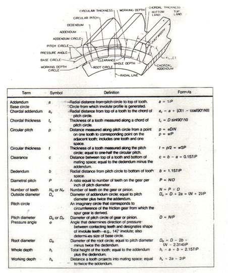
22 Spur Gear Nomenclature Pitch Circle(s) The circles remain tangent throughout entire engagement Pitch Diameter Diameter of pitch circle D P Pitch φ of pinion D G Pitch φ of gear (power gear or driving gear) (Driven gear)
23 Gear Nomenclature N Number of teeth Use subscript for specific gear N P Number of teeth on pinion (driver) N G Number of teeth on gear (driven) N P < N G (for speed reducer) N A Number of teeth on gear A Circular Pitch, P is the radial distance from a point on a tooth at the pitch circle to corresponding point on the next adjacent tooth P(π D)/N
24 Gear Nomenclature Gear Train Rule Pitch of two gears in mesh must be identical PINION P πd G N G πd P N P GEAR
25 Gear Nomenclature Diametral Pitch, (P d ) Number of teeth per inch of pitch diameter P d N D *Two gears in mesh must have equal P d : P d N G D G N P D P *Standard diametral pitches can be found in Table 8-1 and 8-2
26 Gear Nomenclature Figure 8-8 More Gear Nomenclature:
27

28 Gear Geometry Spur Gears Tooth Profile Conjugate shape Conjugate Profile Tooth is thicker at base, maximum moment σ M/s Pressure Angle (φ) - angle between tangent and perpendicular line to gear tooth surface Allows constant velocity ratio between mating gears and smooth power transmission Conjugate profile Fillet Radius

29 Pressure Angle Force perpendicular at φ Φ 14.5 Φ 20 Φ 25

30 Figure 8-11
31 Gear Nomenclature Example 8-1) Gear has 44 teeth, 20, full depth involute form diametral pitch Pd 12 Pitch Diameter N G D G Pd Circular Pitch 44 teeth 12 t/in inch P c π D G N G (π) 3.667in 44 t.2617 in/t
32 Gear Nomenclature Example Addendum a Dedendum 1 Pd 1 12 t/in.0833 in b 1.25 Pd t/in.1042 in
33 Gear Nomenclature Example Clearance c.25 Pd t/in.0208 in Whole Depth ht a+b.1875 in Working Depth hk 2*a in
34 Gear Nomenclature Example Tooth Thickness t P C in in Outside Diameter O.D. D O N+2 Pd in
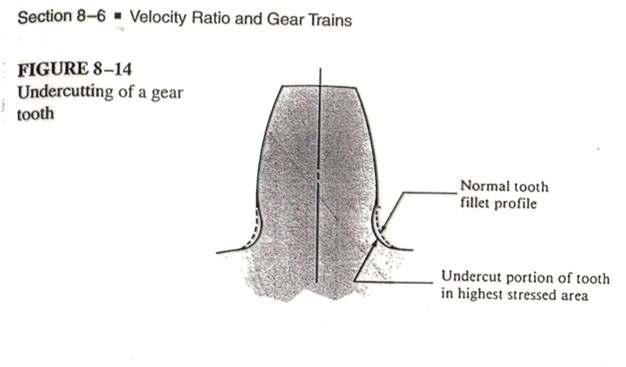
35 Gear Nomenclature Notes Clearance maybe a problem for small pinions driving large gears, therefore they won t mesh and will lock up (See Table 8-6) As N P decreases so does max N G If design necessatates small pinion, maybe able to increase clearance by undercutting gear tooth (See Figure 8-14)
36
37 Summary of Gear Nomenclature: D P Pitch diameter of pinion D G Pitch diameter of gear N P No. teeth (t) for pinion N G No. teeth (t) or gear P d diametral pitch N/D constant for meshing gears p circular pitch πd/n constant for meshing gears n P speed of pinion (rpm) n G speed of gear (rpm) VR velocity ratio n P /n G N G /N P Power constant across mating gears or series system: Pin Pout Power in branched system is conserved: Pin P A + P B +.. Torque will change!! Torque( lb in) 63,000 hp rpm
38 Conclusion: Total speed reduction 1750/ Torque increase 25.7 Power constant!!
39 Gear Trains Train Value TV Product of the values for each gear pair in the train n in TV (VR1)(VR2).... n out
40 Gear Train Alternate Solution TV (VR 1 )(VR 2 )(VR 3 ) 30 TV * * TV n i n out n i n out TV 1750 rpm rpm ccw T out 8.4 T in!! Lots of Torque
41 YouTube Gear Animations: Speed Reducers: Automotive Differential: Manual Transmission: Gear Cutting:
1/2/2015 2:04 PM. Chapter 13. Gears General. Dr. Mohammad Suliman Abuhaiba, PE
 Chapter 13 Gears General 1 2 Chapter Outline 1. Types of Gears 2. Nomenclature 3. Conjugate Action 4. Involute Properties 5. Fundamentals 6. Contact Ratio 7. Interference 8. The Forming of Gear Teeth 9.
12/6/2013 9:09 PM. Chapter 13. Gears General. Dr. Mohammad Suliman Abuhaiba, PE
 Chapter 13 Gears General 1 2 Chapter Outline 1. Types of Gears 2. Nomenclature 3. Conjugate Action 4. Involute Properties 5. Fundamentals 6. Contact Ratio 7. Interference 8. The Forming of Gear Teeth 9.
GEAR CONTENTS POWER TRANSMISSION GEAR TYPES OF GEARS NOMENCLATURE APPLICATIONS OF GEARS VELOCITY RATIO GEAR TRAINS EXAMPLE PROBLEMS AND QUESTIONS
 GEAR CONTENTS POWER TRANSMISSION GEAR TYPES OF GEARS NOMENCLATURE APPLICATIONS OF GEARS VELOCITY RATIO GEAR TRAINS EXAMPLE PROBLEMS AND QUESTIONS GEAR.. Power transmission is the movement of energy from
Part VII: Gear Systems: Analysis
 Part VII: Gear Systems: Analysis This section will review standard gear systems and will provide the basic tools to perform analysis on these systems. The areas covered in this section are: 1) Gears 101:
Gear Tooth Geometry - This is determined primarily by pitch, depth and pressure angle
 Gear Tooth Geometry - This is determined primarily by pitch, depth and pressure angle Addendum: The radial distance between the top land and the pitch circle. Addendum Circle: The circle defining the outer
CH#13 Gears-General. Drive and Driven Gears 3/13/2018
 CH#13 Gears-General A toothed wheel that engages another toothed mechanism in order to change the speed or direction of transmitted motion The gear set transmits rotary motion and force. Gears are used
Catalog Q Conversion For those wishing to ease themselves into working with metric gears
 1.3.4 Conversion For those wishing to ease themselves into working with metric gears by looking at them in terms of familiar inch gearing relationships and mathematics, Table 1-5 is offered as a means
Lecture (7) on. Gear Measurement. By Dr. Emad M. Saad. Industrial Engineering Dept. Faculty of Engineering. Fayoum University.
 on. Gear Measurement. By Dr. Emad M. Saad. Industrial Engineering Dept. Faculty of Engineering. Fayoum University.") 1 Lecture (7) on Gear Measurement Fayoum University By Dr. Emad M. Saad Industrial Engineering Dept. Faculty of Engineering Fayoum University Faculty of Engineering Industrial Engineering Dept. 2015-2016
1 Lecture (7) on Gear Measurement Fayoum University By Dr. Emad M. Saad Industrial Engineering Dept. Faculty of Engineering Fayoum University Faculty of Engineering Industrial Engineering Dept. 2015-2016
Chapter 3. Transmission Components
 Chapter 3. Transmission Components The difference between machine design and structure design An important design problem in a mechanical system is how to transmit and convert power to achieve required
Introduction. Kinematics and Dynamics of Machines. Involute profile. 7. Gears
 Introduction The kinematic function of gears is to transfer rotational motion from one shaft to another Kinematics and Dynamics of Machines 7. Gears Since these shafts may be parallel, perpendicular, or
(POWER TRANSMISSION Methods)
") UNIT-5 (POWER TRANSMISSION Methods) It is a method by which you can transfer cyclic motion from one place to another or one pulley to another pulley. The ways by which we can transfer cyclic motion are:-
UNIT-5 (POWER TRANSMISSION Methods) It is a method by which you can transfer cyclic motion from one place to another or one pulley to another pulley. The ways by which we can transfer cyclic motion are:-
Chapter seven. Gears. Laith Batarseh
 Chapter seven Gears Laith Batarseh Gears are very important in power transmission between a drive rotor and driven rotor What are the functions of gears? - Transmit motion and torque (power) between shafts
UNIT -I. Ans: They are specified by the no. of strands & the no. of wires in each strand.
 VETRI VINAYAHA COLLEGE OF ENGINEERING AND TECHNOLOGY, THOTTIAM, NAMAKKAL-621215. DEPARTMENT OF MECHANICAL ENGINEERING SIXTH SEMESTER / III YEAR ME6601 DESIGN OF TRANSMISSION SYSTEM (Regulation-2013) UNIT
ME6601 DESIGN OF TRANSMISSION SYSTEMS
 SYED AMMAL ENGINEERING COLLEGE (Approved by the AICTE, New Delhi, Govt. of Tamilnadu and Affiliated to Anna University, Chennai) Established in 1998 - An ISO 9001:2008 Certified Institution Dr. E.M.Abdullah
KINGS COLLEGE OF ENGINEERING DEPARTMENT OF MECHANICAL ENGINEERING
 KINGS COLLEGE OF ENGINEERING DEPARTMENT OF MECHANICAL ENGINEERING QUESTION BANK Sub Code/Name: ME 1352 DESIGN OF TRANSMISSION SYSTEMS Year/Sem: III / VI UNIT-I (Design of transmission systems for flexible
What are the functions of gears? What is gear?
 8//0 hapter seven Laith atarseh are very important in power transmission between a drive rotor and driven rotor What are the functions of gears? - Transmit motion and torque (power) between shafts - Maintain
1.6 Features of common gears
 1.6 Features of common gears Chapter 1.2 covered briefly on types of gear. The main gear features are explained here. Helical gear Helical gear has characteristics of transferability of larger load, less
Engineering Information
 Engineering nformation Gear Nomenclature ADDENDUM (a) is the height by which a tooth projects beyond the pitch circle or pitch line. BASE DAMETER (D b ) is the diameter of the base cylinder from which
Spur Gears. Helical Gears. Bevel Gears. Worm Gears
 Spur s General: Spur gears are the most commonly used gear type. They are characterized by teeth which are perpendicular to the face of the gear. Spur gears are by far the most commonly available, and
Mechanism Feasibility Design Task
 Mechanism Feasibility Design Task Dr. James Gopsill 1 Contents 1. Last Week 2. Types of Gear 3. Gear Definitions 4. Gear Forces 5. Multi-Stage Gearbox Example 6. Gearbox Design Report Section 7. This Weeks
INVOLUTE SPIRAL FACE COUPLINGS AND GEARS: DESIGN APPROACH AND MANUFACTURING TECHNIQUE
 УДК 621.9.015 Dr. Alexander L. Kapelevich, Stephen D. Korosec 38 INVOLUTE SPIRAL FACE COUPLINGS AND GEARS: DESIGN APPROACH AND MANUFACTURING TECHNIQUE This paper presents spiral face gears with an involute
Basic Fundamentals of Gear Drives
 Basic Fundamentals of Gear Drives Course No: M06-031 Credit: 6 PDH A. Bhatia Continuing Education and Development, Inc. 9 Greyridge Farm Court Stony Point, NY 10980 P: (877) 322-5800 F: (877) 322-4774
11. GEAR TRANSMISSIONS
 11. GEAR TRANSMISSIONS 11.1. GENERAL CONSIDERATIONS Gears are one of the most important elements used in machinery. There are few mechanical devices that do not have the need to transmit power and motion
Instantaneous Centre Method
 Instantaneous Centre Method The combined motion of rotation and translation of the link AB may be assumed to be a motion of pure rotation about some centre I, known as the instantaneous centre of rotation.
SECTION 8 BEVEL GEARING
 SECTION 8 BEVEL GEARING For intersecting shafts, bevel gears offer a good means of transmitting motion and power. Most transmissions occur at right angles, Figure 8-1, but the shaft angle can be any value.
Introduction to Gear Design
 Introduction to Gear Design Course No: M03-016 Credit: 3 PDH Robert P. Tata, P.E. Continuing Education and Development, Inc. 9 Greyridge Farm Court Stony Point, NY 10980 P: (877) 322-5800 F: (877) 322-4774
Bevel Gears. Fig.(1) Bevel gears
 Bevel gears") Bevel Gears Bevel gears are cut on conical blanks to be used to transmit motion between intersecting shafts. The simplest bevel gear type is the straighttooth bevel gear or straight bevel gear as can be
Bevel Gears Bevel gears are cut on conical blanks to be used to transmit motion between intersecting shafts. The simplest bevel gear type is the straighttooth bevel gear or straight bevel gear as can be
Gear Engineering Data. Spur Gear Gear Formulas Drive Selection Horsepower and Torque Tables
 Engineering Gear Engineering Data Spur Gear Gear Formulas Drive Selection Horsepower and Torque Tables G-79 Gear Selection Stock Spur Gear Drive Selection When designing a stock gear drive using the horsepower
 DEPARTMENT OF MECHANICAL ENGINEERING Subject code: ME6601 Subject Name: DESIGN OF TRANSMISSION SYSTEMS UNIT-I DESIGN OF TRANSMISSION SYSTEMS FOR FLEXIBLE ELEMENTS 1. What is the effect of centre distance
Program Internal Gear Set Profile Shift Coefficients With Zero Backlash Introduction
 Program 60-107 Internal Gear Set Profile Shift Coefficients With Zero Backlash Introduction The purpose of this model is to provide data for a gear set when the tooth thickness and/or the center distance
The Geometry of Involute Gears
 The Geometry of Involute Gears J.R. Colbourne The Geometry of Involute Gears With 217 Illustrations Springer-Verlag New York Berlin Heidelberg London Paris Tokyo J.R. Colbourne Department of Mechanical
Session #3 Gears: Force Transmission & Gear Trains. Dan Frey
 Session #3 Gears: Force Transmission & Gear Trains Dan Frey Today s Agenda Pass out second reading packet Pass out loaner laptops Introduce project teams Gears Force Transmission Gear Trains Survey HW
Gear Measurement. Lecture (7) Mechanical Measurements
 Mechanical Measurements") 18 3. Gear profile checking 2. Involute measuring machine In this method the gear is held on a mandrel and circular disc of same diameter as the base circle of gear for the measurement is fixed on the
18 3. Gear profile checking 2. Involute measuring machine In this method the gear is held on a mandrel and circular disc of same diameter as the base circle of gear for the measurement is fixed on the
Copyright Notice. Small Motor, Gearmotor and Control Handbook Copyright Bodine Electric Company. All rights reserved.
 Copyright Notice Small Motor, Gearmotor and Control Handbook Copyright 1993-2003 Bodine Electric Company. All rights reserved. Unauthorized duplication, distribution, or modification of this publication,
GEARBOXES. Gearboxes. Gearboxes. Gearbox is a mechanical device utilized to increase the output torque or change
 GEARBOXES Gearboxes Gearboxes Gearbox is a mechanical device utilized to increase the output torque or change the speed of a motor. The motor's shaft is attached to one end of the gearbox and through the
T25 T25 T25 T27 T27 T28 T28 T28 T28 T29 T29 T29 T31 T37 T37 T38 T T T48
 1.0 INTRODUCTION 2.0 BASIC GEOMETRY OF SPUR GEARS 2.1 Basic Spur Gear Geometry 2.2 The Law of Gearing 2.3 The Involute Curve 2.4 Pitch Circles 2.5 Pitch 2.5.1 Circular Pitch 2.5.2 Diametral Pitch 2.5.3
Lecture 13 BEVEL GEARS
 Lecture 13 BEVEL GEARS CONTENTS 1. Bevel gear geometry and terminology 2. Bevel gear force analysis 3. Bending stress analysis 4. Contact stress analysis 5. Permissible bending fatigue stress 6. Permissible
Sheet 1 Variable loading
 Sheet 1 Variable loading 1. Estimate S e for the following materials: a. AISI 1020 CD steel. b. AISI 1080 HR steel. c. 2024 T3 aluminum. d. AISI 4340 steel heat-treated to a tensile strength of 1700 MPa.
Unit IV GEARS. Gallery
 Gallery Components of a typical, four stroke cycle, DOHC piston engine. (E) Exhaust camshaft, (I) Intake camshaft, (S) Spark plug, (V) Valves, (P) Piston, (R) Connecting rod, (C) Crankshaft, (W) Water
Simple Gears and Transmission
 Simple Gears and Transmission Simple Gears and Transmission page: of 4 How can transmissions be designed so that they provide the force, speed and direction required and how efficient will the design be?
ME6401 KINEMATICS OF MACHINERY UNIT- I (Basics of Mechanism)
") ME6401 KINEMATICS OF MACHINERY UNIT- I (Basics of Mechanism) 1) Define resistant body. 2) Define Link or Element 3) Differentiate Machine and Structure 4) Define Kinematic Pair. 5) Define Kinematic Chain.
ME6401 KINEMATICS OF MACHINERY UNIT- I (Basics of Mechanism) 1) Define resistant body. 2) Define Link or Element 3) Differentiate Machine and Structure 4) Define Kinematic Pair. 5) Define Kinematic Chain.
Different types of gears. Spur gears. Idler gears. Worm gears. Bevel gears. Belts & Pulleys
 GEARS Robot Gears By using different gear diameters, you can exchange between rotational (or translation) velocity and torque. by looking at the motor datasheet you can determine the output velocity and
TECHNOLOGY MECHANISMS
 TECHNOLOGY MECHANISMS 3º ESO IES CHAN DO MONTE URTAZA 1 WHAT IS A MECHANISM? Mechanism are devices that have been designed to make jobs easier. They all have certain things in common: They involve some
Bevel Gears n A Textbook of Machine Design
 080 n A Textbook of Machine Design C H A P T E R 30 Bevel Gears. Introduction.. Classification of Bevel Gears. 3. Terms used in Bevel Gears. 4. Determination of Pitch Angle for Bevel Gears. 5. Proportions
Technology of Machine Tools
 PowerPoint to accompany Technology of Machine Tools 6 th Edition Krar Gill Smid Gear Cutting Unit 70 Copyright The McGraw-Hill Companies, Inc. Permission required for reproduction or display. 70-2 Objectives
Metrology Prof. Dr Kanakuppi Sadashivappa Bapuji Institute of Engineering and Technology Davangere. Lecture 25 Introduction of Gears
 Metrology Prof. Dr Kanakuppi Sadashivappa Bapuji Institute of Engineering and Technology Davangere Lecture 25 Introduction of Gears I welcome you for the series of lecture on gear measurement and at module
Bibliography. [1] Buckingham, Earle: "Analytical Mechanics of Gears", McGraw-Hill, New York, 1949, and republished by Dover, New York, 1963.
![Bibliography. [1] Buckingham, Earle: Analytical Mechanics of Gears, McGraw-Hill, New York, 1949, and republished by Dover, New York, 1963.](/thumbs/87/96820687.jpg "Bibliography. [1] Buckingham, Earle: Analytical Mechanics of Gears, McGraw-Hill, New York, 1949, and republished by Dover, New York, 1963.") Bibliography The first five references listed are books on gearing. Some of them deal not only with the geometry, but also with many other aspects of gearing. However, the books are included in this bibliography
Bibliography The first five references listed are books on gearing. Some of them deal not only with the geometry, but also with many other aspects of gearing. However, the books are included in this bibliography
Fig. 1 Two stage helical gearbox
 Lecture 17 DESIGN OF GEARBOX Contents 1. Commercial gearboxes 2. Gearbox design. COMMERICAL GEARBOX DESIGN Fig. 1 Two stage helical gearbox Fig. 2. A single stage bevel gearbox Fig. 4 Worm gearbox HELICAL
11/23/2013. Chapter 13. Gear Trains. Dr. Mohammad Suliman Abuhiba, PE
 Chapter 13 Gear Trains 1 2 13.2. Types of Gear Trains 1. Simple gear train 2. Compound gear train 3. Reverted gear train 4. Epicyclic gear train: axes of shafts on which the gears are mounted may move
Tooth thickness Dedendum. Addendum. Centre distance Nominal
 FORMULAS SPUR GEARS TO FIND:- PCD ØD MODULE No. of TEETH CP ADDENDUM DEDENDUM MODULE No. of TEETH x MOD (mm) (No. of TEETH + ) x MOD (mm) 5.4 MODULE CP π (mm) PCD MODULE (mm) MODULE x π (mm) MODULE (mm)
CHAPTER 5 PREVENTION OF TOOTH DAMAGE IN HELICAL GEAR BY PROFILE MODIFICATION
 90 CHAPTER 5 PREVENTION OF TOOTH DAMAGE IN HELICAL GEAR BY PROFILE MODIFICATION 5.1 INTRODUCTION In any gear drive the absolute and the relative transmission error variations normally increases with an
2. a) What is pantograph? What are its uses? b) Prove that the peaucellier mechanism generates a straight-line motion. (5M+10M)
 What is pantograph? What are its uses? b) Prove that the peaucellier mechanism generates a straight-line motion. (5M+10M)") Code No: R22032 R10 SET - 1 1. a) Define the following terms? i) Link ii) Kinematic pair iii) Degrees of freedom b) What are the inversions of double slider crank chain? Describe any two with neat sketches.
Code No: R22032 R10 SET - 1 1. a) Define the following terms? i) Link ii) Kinematic pair iii) Degrees of freedom b) What are the inversions of double slider crank chain? Describe any two with neat sketches.
Effect of Geometry Factor I & J Factor Multipliers in the performance of Helical Gears
 Effect of Geometry Factor I & J Factor Multipliers in the performance of Helical Gears 1 Amit D. Modi, 2 Manan B. Raval, 1 Lecturer, 2 Lecturer, 1 Department of Mechanical Engineering, 2 Department of
Design of Helical Gear and Analysis on Gear Tooth
 Design of Helical Gear and Analysis on Gear Tooth Indrale Ratnadeep Ramesh Rao M.Tech Student ABSTRACT Gears are mainly used to transmit the power in mechanical power transmission systems. These gears
Design and Analysis of Six Speed Gear Box
 Design and Analysis of Six Speed Gear Box Ujjayan Majumdar 1, Sujit Maity 2, Gora Chand Chell 3 1,2 Student, Department of Mechanical Engineering, Jalpaiguri Government Engineering College, Jalpaiguri,
BRCM COLLEGE OF ENGINEERING & TECHNOLOGY BAHAL, BHIWANI Practical Experiment Instructions Sheet
 BRCM COLLEGE OF KOM ME- 212 F KINEMATICS OF MACHINES LAB BRANCH-ME List of Experiments : 1. To study various types of Kinematic links, pairs, chains and Mechanisms. 2. To study inversions of 4 Bar Mechanisms,
Chain Drives. Pitch. Basic Types -There are six major types of power-
 1 2 Power transmission chains have two things in common; side bars or link plates, and pin and bushing joints. The chain articulates at each joint to operate around a toothed sprocket. The pitch of the
A comparison of the gear calculation process according to Swedish and American textbooks for higher education
 World Transactions on Engineering and Technology Education Vol.6, No.1, 2007 2007 UICEE A comparison of the gear calculation process according to Swedish and American textbooks for higher education Samir
SECTION 4 SPUR GEAR CALCULATIONS
 Function of α, or invα, is known as involute function. Involute function is very important in gear design. Involute function values can be obtained from appropriate tables. With the 3.1 Contact Ratio center
Finite element analysis of profile modified spur gear
 Finite element analysis of profile modified spur gear Sagar Gaur Mechanical Engineering Department, Institute of Technology, YashluvVirwani Mechanical Engineering Department, Institute of Technology, Rudresh
1.8 Rack shift of the gear
 1.8 Rack shift of the gear Undercut When Number of teeth is belo minimum as shon in Fig. 3, part of dedendum is no longer an Involute curve but ill look like a shape scooped out by cutter tool. Refer to
we will learn how to conduct force and torque analysis on gears in order to calculate bearing
 8.1 Introduction to Gears Gears are used to transmit motion and torque from one shaft to another. In this section we will discuss the kinematics of gears; that is, the motion relationships between gears.
Chapter 1 Gear Design
 Chapter 1 Gear Design GTU Paper Analysis Sr. No. Questions Nov 16 May 17 Nov 17 May 18 Theory 1. Explain the following terms used in helical gears: (a) Helix angle; (b) Normal pitch; (c) Axial pitch; (d)
1.7 Backlash. Summary of the backlash is play or clearance between one pair of gear. Fig. 17 Backlash
 1.7 Backlash Summary of the backlash is play or clearance between one pair of gear. Fig. 17 Backlash Great care is taken to produce the gear with zero deviation. However we are unable to completely eliminate
CHAPTER 6 GEARS CHAPTER LEARNING OBJECTIVES
 CHAPTER 6 GEARS CHAPTER LEARNING OBJECTIVES Upon completion of this chapter, you should be able to do the following: Compare the types of gears and their advantages. Did you ever take a clock apart to
KINEMATICS OF MACHINARY UBMC302 QUESTION BANK UNIT-I BASICS OF MECHANISMS PART-A
 KINEMATICS OF MACHINARY UBMC302 QUESTION BANK UNIT-I BASICS OF MECHANISMS PART-A 1. Define the term Kinematic link. 2. Classify kinematic links. 3. What is Mechanism? 4. Define the terms Kinematic pair.
Graphical representation of a gear
 Homework 4 Gears Gears are designed to transmit rotary motion. Often they are arranged in a gear train (meshed together). Gear trains provide a change in speed, torque (turning force) and direction (clockwise
SYED AMMAL ENGINEERING COLLEGE
 SYED AMMAL ENGINEERING COLLEGE (Approved by the AICTE, New Delhi, Govt. of Tamilnadu and Affiliated to Anna University, Chennai) Established in 1998 - An ISO 9001:2000 Certified Institution Dr. E.M.Abdullah
GEARING. Theory of. Stephen. Kinetics, Geometry, and Synthesis. P. Radzevich. /Ov CRC Press yc*** J Taylor& Francis Croup Boca Raton
 Theory of GEARING Kinetics, Geometry, and Synthesis Stephen P. Radzevich /Ov CRC Press yc*** J Taylor& Francis Croup Boca Raton London New York CRC Press is an imprint of the Taylor & Francis Group, an
MECHANICAL DRIVES 1 SPUR GEAR DRIVES LEARNING ACTIVITY PACKET BB502-XD06AEN
 MECHANICAL DRIVES 1 LEARNING ACTIVITY PACKET SPUR GEAR DRIVES BB502-XD06AEN LEARNING ACTIVITY PACKET 6 SPUR GEAR DRIVES INTRODUCTION This LAP will begin the study of the third type of adjacent shaft-to-shaft
ANALYSIS OF STRESSES AND DEFLECTIONS IN SPUR GEAR
 International Journal of Mechanical Engineering and Technology (IJMET) Volume 8, Issue 4, April 2017, pp. 461 473 Article ID: IJMET_08_04_050 Available online at http://www.iaeme.com/ijmet/issues.asp?jtype=ijmet&vtype=8&itype=4
Mechanical Power Transmission. September 16, 2008
 2008 TE Sessions Supported by Mechanical Power Transmission September 16, 2008 www.robojackets.org Goals Hand out kits to teams that don t have one. More physics concepts and terms Understanding key devices
STATIC ANALYSIS ON BEVEL GEAR USING STRUCTURAL STEEL, GRAY CAST IRON, AND STAINLESS STEEL
 STATIC ANALYSIS ON BEVEL GEAR USING STRUCTURAL STEEL, GRAY CAST IRON, AND STAINLESS STEEL Prateek Srivastava 1, Rishabh 2, Zubair Irshad 3, Pankaj Kumar Singh 4 Graduate Students Mechanical Engineering,
1. (a) Discuss various types of Kinematic links with examples. (b) Explain different types of constrained motions with examples.
 Discuss various types of Kinematic links with examples. (b) Explain different types of constrained motions with examples.") Code No: RR310304 Set No. 1 III B.Tech I Semester Supplementary Examinations, February 2007 KINEMATICS OF MACHINERY ( Common to Mechanical Engineering, Mechatronics and Production Engineering) Time: 3
Code No: RR310304 Set No. 1 III B.Tech I Semester Supplementary Examinations, February 2007 KINEMATICS OF MACHINERY ( Common to Mechanical Engineering, Mechatronics and Production Engineering) Time: 3
Driver Driven. InputSpeed. Gears
 Gears Gears are toothed wheels designed to transmit rotary motion and power from one part of a mechanism to another. They are fitted to shafts with special devices called keys (or splines) that ensure
ENGINEERING INFORMA TION
 SUR GEARS GEAR NOMENCLATURE ENGINEERING INFORMA TION ADDENDUM (a) is the height by which a tooth projects beyond the pitch circle or pitch line. BASE DIAMETER (D b ) is the diameter of the base cylinder
A Study on Noncircular Gears with Non-Uniform Teeth
 A Study on Noncircular Gears with Non-Uniform Teeth Kazushi Kumagai* 1 and Tetsuya Oizumi* *1 Department of Infomation System, Sendai National College of Technology 4-16-1 Ayashi-Chuo, Aoba-ku, Sendai
Customer Application Examples
 Customer Application Examples The New, Powerful Gearwheel Module 1 SIMPACK Usermeeting 2006 Baden-Baden 21. 22. March 2006 The New, Powerful Gearwheel Module L. Mauer INTEC GmbH Wessling Customer Application
The Basics of Gear Theory
 technical The Basics of Gear Theory Hermann J. Stadtfeld Bevel Gears: By the Book Beginning with our June Issue, Gear Technology is pleased to present a series of full-length chapters excerpted from Dr.
Simple Gears and Transmission
 Simple Gears and Transmission Contents How can transmissions be designed so that they provide the force, speed and direction required and how efficient will the design be? Initial Problem Statement 2 Narrative
MANUFACTURING OF GEAR BOXES
 Profile No.: 29 NIC Code: 29301 MANUFACTURING OF GEAR BOXES 1. INTRODUCTION: Gears play a prominent role in mechanical power transmission. A gear or cogwheel is a rotating machine part having cut teeth,
CHAPTER 3 page 35 PRINCIPLES OF GEAR-TOOTH GENERATION. .1 Angular Velocity Ratio
 CHAPTER 1 page 1..., ATURE, NOTATION AND CONVENTIONS TYPES OF GEAR 1.1 Spur 1.2 Helical 1.3 Double-Helical 1.4 Crossed Helical 1.5 Conical Involute 1.6 Bevel 1.7 Spiral Bevel 1.8 Hypoid 1.9 Worm NOMENCLATURE
UNIT III TRANSMISSION SYSTEMS CONTENTS: Clutch-types and construction Gear boxes- manual and automatic Gear shift mechanisms Over drive Transfer box
 UNIT III TRANSMISSION SYSTEMS CONTENTS: Clutch-types and construction Gear boxes- manual and automatic Gear shift mechanisms Over drive Transfer box Fluid flywheel Torque converter Propeller shaft Slip
Code No: R Set No. 1
 Code No: R05310304 Set No. 1 III B.Tech I Semester Regular Examinations, November 2007 KINEMATICS OF MACHINERY ( Common to Mechanical Engineering, Mechatronics, Production Engineering and Automobile Engineering)
CHENDU COLLEGE OF ENGINEERING & TECHNOLOGY DEPARTMENT OF MECHANICAL ENGINEERING QUESTION BANK IV SEMESTER
 CHENDU COLLEGE OF ENGINEERING & TECHNOLOGY DEPARTMENT OF MECHANICAL ENGINEERING QUESTION BANK IV SEMESTER Sub Code: ME 6401 KINEMATICS OF MACHINERY UNIT-I PART-A 1. Sketch and define Transmission angle
ANALYSIS OF SURFACE CONTACT STRESS FOR A SPUR GEAR OF MATERIAL STEEL 15NI2CR1MO28
 ANALYSIS OF SURFACE CONTACT STRESS FOR A SPUR GEAR OF MATERIAL STEEL 15NI2CR1MO28 D. S. Balaji, S. Prabhakaran and J. Harish Kumar Department of Mechanical Engineering, Chennai, India E-Mail: balajimailer@gmail.com
CHENDU COLLEGE OF ENGINEERING & TECHNOLOGY DEPARTMENT OF MECHANICAL ENGINEERING QUESTION BANK
 CHENDU COLLEGE OF ENGINEERING & TECHNOLOGY DEPARTMENT OF MECHANICAL ENGINEERING QUESTION BANK Sub Code: ME 2342 DESIGN OF TRANSMISSION SYSTEM UNIT - I 1. How the bevel gears are classified? Explain with
A COMPARATIVE STUDY OF DESIGN OF SIMPLE SPUR GEAR TRAIN AND HELICAL GEAR TRAIN WITH A IDLER GEAR BY AGMA METHOD
 A COMPARATIVE STUDY OF DESIGN OF SIMPLE SPUR GEAR TRAIN AND HELICAL GEAR TRAIN WITH A IDLER GEAR BY AGMA METHOD Miss. Kachare Savita M.E. Student of Mechanical Design Engg, VACOE, Ahmednagar, India Savita_K90@rediffmail.com
Gear Drives. A third gear added to the system will rotate in the same direction as the drive gear Equal diameters = Equal number of teeth = Same speed
 Gear Drive Systems Gear Drives Gear Drive: Synchronous mechanical drive that uses gears to transfer power Gear: A toothed wheel that meshes with other toothed wheels to transfer rotational power Pinion
GEAR NOISE REDUCTION BY NEW APPROACHES IN GEAR FINISHING PROCESSES
 GEAR NOISE REDUCTION BY NEW APPROACHES IN GEAR FINISHING PROCESSES Nikam Akshay 1, Patil Shubham 2, Pathak Mayur 3, Pattewar Vitthal 4, Rawanpalle Mangesh 5 1,2,3,4,5 Department of Mechanical Engineering,
MECH 1200 Quiz 2 Review
 Name: Class: Date: MECH 1200 Quiz 2 Review True/False Indicate whether the statement is true or false. 1. Gears are machined toothed wheels that engage other toothed wheels to transfer power and torque.
St.MARTIN S ENGINEERING COLLEGE Dhulapally, Secunderabad
 St.MARTIN S ENGINEERING COLLEGE Dhulapally, Secunderabad-500 014 Subject: Kinematics of Machines Class : MECH-II Group A (Short Answer Questions) UNIT-I 1 Define link, kinematic pair. 2 Define mechanism
GEAR GENERATION GEAR FORMING. Vipin K. Sharma
 GEAR GENERATION GEAR FORMING 1 GEAR MANUFACTURING Manufacturing of gears needs several processing operations in sequential stages depending upon the material and type of the gears and quality desired.
Spiroid High Torque Skew Axis Gearing A TECHNICAL PRIMER F. EVERTZ, M. GANGIREDDY, B. MORK, T. PORTER & A. QUIST
 2016 Spiroid High Torque Skew Axis Gearing A TECHNICAL PRIMER F. EVERTZ, M. GANGIREDDY, B. MORK, T. PORTER & A. QUIST Table of Contents INTRODUCTION PAGE 02 SPIROID GEAR SET CHARACTERISTICS PAGE 03 BASIC
KISSsoft 03/2017 Tutorial 15
 KISSsoft 03/2017 Tutorial 15 Bevel gears KISSsoft AG Rosengartenstrasse 4 8608 Bubikon Switzerland Tel: +41 55 254 20 50 Fax: +41 55 254 20 51 info@kisssoft.ag www.kisssoft.ag Contents 1 Starting KISSsoft...
Contact Analysis of a Helical Gear with Involute Profile
 Contact Analysis of a Helical Gear with Involute Profile J. Satish M. Tech (CAD/CAM) Nova College of Engineering and Technology, Jangareddigudem. ABSTRACT Gears are toothed wheels designed to transmit
Machines and mechanisms
 Machines and mechanisms Contents: 1. Basics and Kinematics of Mechanism 2. Cam and Follower 3. Governor 4. Gear and Gear Train 5. Inertia Force Analysis Basics and Kinematics Mechanism: 1. A rigid body
What Are Gears? What Do They Do?
 What Are Gears? What Do They Do? Pre-Lesson Quiz 1. What is a gear? 2. List as many examples as you can of gears or objects that use gears. 2 Pre-Lesson Quiz Answers 1. What is a gear? A gear is a wheel
Thermal Analysis of Helical and Spiral Gear Train
 International Journal for Ignited Minds (IJIMIINDS) Thermal Analysis of Helical and Spiral Gear Train Dr. D V Ghewade a, S S Nagarale b & A N Pandav c a Principal, Department of Mechanical, GENESIS, Top-Kolhapur,
SPUR GEAR TOOTH STRESS ANALYSIS AND STRESS REDUCTION USING STRESS REDUCING GEOMETRICAL FEATURES
 International Journal of Mechanical Engineering and Technology (IJMET) Volume 6, Issue 9, Sep 2015, pp. 17-29, Article ID: IJMET_06_09_003 Available online at http://www.iaeme.com/ijmet/issues.asp?jtypeijmet&vtype=6&itype=9