Different types of gears. Spur gears. Idler gears. Worm gears. Bevel gears. Belts & Pulleys
|
|
|
- Elmer George
- 5 years ago
- Views:
Transcription
1 GEARS
2 Robot Gears By using different gear diameters, you can exchange between rotational (or translation) velocity and torque. by looking at the motor datasheet you can determine the output velocity and torque of your motor. In robotics you want more torque than speed for better handling and control.


3 Different types of gears Spur gears Idler gears Worm gears Bevel gears Belts & Pulleys
4 Essential Terminology Driver gear with applied force Follower gear doing useful work Idler gear turned by driver & turns follower Gear Train many gears in a row Geared Up large driver, small follower to speed gear train up. Geared Down small driver, large follower to increase torque (turning force) Compound gears combination of gears and axles where one axle has 2 gears often of different sizes.
5 Basic Gear Properties When 2 gears mesh, driver makes follower turn in opposite direction Need odd number of idler gears to make driver and follower turn in same direction. Need 0 or even number of idlers to make driver and follower turn in opposite direction When large driver turns small follower, its called gearing up and speeds up gear train When small driver turns large follower, its called gearing down and increases torque (turning force).

6 Gear Geometry Radius D + Radius F Driver Follower
7 QUESTIONS: A B motor Which gear is the driver (A or B)? Which gear is the follower (A or B)?
? A Which gear is the follower (A or B)?")
8 ANSWERS A B motor Which gear is the driver (A or B)? A Which gear is the follower (A or B)? B
9 QUESTIONS motor wheel A B C Which gear is the follower (A, B, or C)? Which gear is the driver (A, B, or C)? Which gear is the idler (A, B, or C)?
10 ANSWERS motor wheel A B C Which gear is the follower (A, B, or C)? C Which gear is the driver (A, B, or C)? A Which gear is the idler (A, B, or C)? B
11 Direction follower even number of gears: driver & follower turn in opposite directions driver odd number of gears: driver & follower turn in same direction driver follower follower driver
12 QUESTIONS driver Would the follower gear move clockwise or counterclockwise?


13 ANSWERS driver Would the follower gear move clockwise or counterclockwise?


14 QUESTIONS driver Would the follower gear move clockwise or counterclockwise?
15 ANSWERS driver Would the follower gear move clockwise or counterclockwise?


16 Geared Up large driver turns small follower increases speed decreases torque (turning force) follower driver driven gear follower gear
 decreases speed driver follower driven gear")
17 Geared Down small driver turns large follower increases torque (turning force) decreases speed driver follower driven gear follower gear


18 Gears (Spur) Meshing Horizontally Possible to mesh at stud lengths of 1 through 5

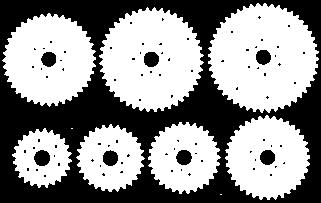
19 Spur Gears Most common type of gear, a wheel with teeth. beam axle (put bushings on the back side) Spur gears do three things. 1. Change rot. speed 2. Change torque 3. Change direction 8 tooth gear 40 tooth gear Make sure there isn t too much friction between the gears and the beam. The gears should spin easily.


20 Gears (Spur) Meshing Vertically 2 4 Using 24 tooth and 8 tooth at distance of 2 stud lengths Using 24 tooth and 40 tooth at distance of 4 stud lengths Mesh at even stud lengths for best results
21 NOMENCLATURE OF SPUR GEARS See Gears Kinematics Reference for more information
22 NOMENCLATURE. Pitch surface: The surface of the imaginary rolling cylinder (cone, etc.) that the toothed gear may be considered to replace. Pitch circle: A right section of the pitch surface. Addendum circle: A circle bounding the ends of the teeth, in a right section of the gear. Root (or dedendum) circle: The circle bounding the spaces between the teeth, in a right section of the gear. Addendum: The radial distance between the pitch circle and the addendum circle. Dedendum: The radial distance between the pitch circle and the root circle. Clearance: The difference between the dedendum of one gear and the addendum of the mating gear.
23 NOMENCLATURE. Face of a tooth: That part of the tooth surface lying outside the pitch surface. Flank of a tooth: The part of the tooth surface lying inside the pitch surface. Circular thickness (also called the tooth thickness): The thickness of the tooth measured on the pitch circle. It is the length of an arc and not the length of a straight line. Tooth space: pitch diameter The distance between adjacent teeth measured on the pitch circle. Backlash: The difference between the circle thickness of one gear and the tooth space of the mating gear. Circular pitch (Pc) : The width of a tooth and a space, measured on the pitch circle.
24 What happens with improper mesh? When 2 gears are meshed, there is a certain amount of built in play between them called backlash. When 2 gears are not meshed properly i.e. within specification you get too much backlash called slop OR too little backlash and they are jammed together and this creates friction.

25 Gears (Spur) Meshing Diagonally Slop or friction typically occurs when you make gears mesh diagonally Some Schools of Thought 1. Don t do it as it makes gears out of specification and something may go wrong e.g. gear teeth skipping 2. Do it as it gives you more creativity in meshing gears in different configurations. 3. Do it but within some tolerance e.g. under 1%
26 What is the best type of gear teeth? Gears need to have teeth that mesh properly otherwise they will not work. Best is a curve on the teeth that provides for constant velocity when gear turning Involute curves modeled on the teeth provides this advantage and is the basis for most modern gears.

27 Gear Tooth Geometry The involute curve can be generated by wrapping a string around a circle. Ideal Gear Tooth Shape
28 MESHING OF GEAR TEETH
29 Gear Ratio In order to determine what a gear will do for us, we must quantify it. Best measure is the gear ratio. Gear Ratio = number of teeth in follower number of teeth in driver G.R. = F t / D t e.g. ⅓ or 1:3 (read as 1 to 3) Interpret above as one turn of driver will turn the follower 3 times.
30 What is the gear ratio? 84 tooth driver 60 tooth follower
31 What is the gear ratio? Show Videos driver follower 5 to 7 or 5:7 follower teeth 60 teeth gear ratio = = = driver teeth 84 teeth 5 7
32 Idler Gears An idler gear is a gear that is inserted between 2 other gears. idler gear 8 tooth gear to the right of the 40 tooth gear. How many turns of the 8 tooth gear on the left does it take to make 1 turn of the new 8 tooth gear on the right?

33 Idler Gears Answer: 1! It s as if the 8 tooth gears are meshed together. Idler gears DO NOT change the gear ratio. Idler gears DO make both 8 tooth gears rotate in the same direction, add spacing between gears.
34 Long Gear Trains The gear attached to the motor is the driver. The gear doing work is the follower. All in-between gears are idlers. Ignore the idler gears! Driver Follower Gear Ratio = 24 / 40 = 3 / 5 3 turns of the 40 tooth gear will turn the 24 tooth gear 5 times. Idlers
35 Compound Gears (Multiple Gears on One Axle) 1. Pair up drivers and followers 2. Start a new driver/follower pair if an axle has a second gear attached. 3. Multiply the gear ratios of all the driver/follower pairs. D 2 Gear 1 = 12 teeth Gear 3 = 12 teeth Gear 2 = 36 teeth Gear 4 = 60 teeth
36 Compound Gears (Multiple Gears on One Axle) 1. Pair up drivers and followers 2. Start a new driver/follower pair if an axle has a second gear attached. 3. Multiply the gear ratios of all the driver/follower pairs. Gear 1 & Gear 2: follower driver = = 3 1 D 2 Gear 1 = 12 teeth Gear 3 = 12 teeth Gear 2 = 36 teeth Gear 4 = 60 teeth
37 1. Pair up drivers and followers Compound Gears (Multiple Gears on One Axle) 2. Start a new driver/follower pair if an axle has a second gear attached. 3. Multiply the gear ratios of all the driver/follower pairs. Gear 1 & Gear 2: follower driver = = 3 1 Gear 1 = 12 teeth Gear 3 = 12 teeth D 2 Gear 2 = 36 teeth Gear 4 = 60 teeth Gear 3 & Gear 4: follower 60 = = driver x 5 1 = Multiply the gear ratios:

38 1. Pair up drivers and followers Compound Gears (Multiple Gears on One Axle) 2.Start a new driver/follower pair if an axle has a second gear attached. 1. Multiply the gear ratios of all the driver/follower pairs. Gear 1 & Gear 2: follower driver = = 3 1 Gear 1 = 12 teeth Gear 3 = 12 teeth D 2 Gear 2 = 36 teeth Gear 4 = 60 teeth Gear 3 & Gear 4: follower 60 = = driver = Multiply the gear ratios: 15:1
39 Calculate the Gear Ratio (Assume the last axle does the useful work) 60t 36t 12t 12t 12t 36t
40 Calculate the Gear Ratio (Assume the last axle does the useful work) Pair 1: 12t 36t 12t 60t follower driver = = t 36t
41 Calculate the Gear Ratio (Assume the last axle does the useful work) 12t 12t 36t 12t 36t t 3 4 follower driver = Pair 2: follower 36 = = driver 12 Pair 1: 3 = 1 3 1
42 Calculate the Gear Ratio (Assume the last axle does the useful work) 12t 12t 36t 12t 36t t 3 4 follower driver = = Pair 2: follower 36 = = driver 12 Pair 3: follower 60 = = driver 12 Pair 1:

43 Calculate the Gear Ratio (Assume the last axle does the useful work) 12t 36t 12t 60t follower driver Pair 2: 36 = 12 Pair 1: 3 = 1 12t 36t follower = driver Pair 3: = 3 1 follower driver = = 5 1 Multiply the gear ratios: = :1

44 Clever 2-Speed Transmission!
45 Calculate This: 60 tooth 36 tooth 60 tooth 36 tooth 60 tooth 60 tooth Is this transmission currently geared up or down? geared down What is the current gear ratio of this transmission? 60:36 = 5:3 What is the gear ratio of the other set of gears? 60:60 = 1:1

46 Calculate This: 60 tooth 36 tooth 60 tooth 36 tooth 60 tooth 60 tooth Is this transmission currently geared up or down? geared down What is the current gear ratio of this transmission? 60:36 = 5:3 What is the gear ratio of the other set of gears? 60:60 = 1:1


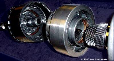
47 Bevel Gears Bevel gears are spur gears that mesh at a 90 degree angle. The gear ratio rules remain the same, but the axles are perpendicular to one another. These 12 tooth bevel gears can only mesh with them-selves.


48 Where Can You Find a Bevel Gear? Hand drill Car differential Shaft-driven bicycle The bevel gear is used to change rotational motion at a 90 angle. Using gears with differing numbers of teeth will change the speed and torque.


49 Worm Gears 1x6 beam 1 #6 axle x4 plates half bushing 4 24 tooth gear 1x4 beam 5 worm gear full bushing #10 axle
50 Worm Gears Worm gears have some special properties. 1: The axles are perpendicular, like bevel gears. 2: How many rotations of the worm gear does it take for 1 rotation of the spur gear? ANSWER: 24! The worm gear acts like a gear with 1 tooth! This gives very large gear ratios.
51 Worm Gears Worm gears are not back-driveable. You can turn the worm gear s axle, but you can t turn the spur gear s axle. This property is used as a locking mechanism.
52 Gear Analysis To analyze any gear train you need to: 1. Locate the driver gear (see force applied) 2. Locate the follower gear (see where useful work done) 3. Figure out if it is geared up or geared down (big circle turning small circle geared up) 4. Calculate the Gear Ratio using F t /D t. Use the following 3 rules for gear ratio calculation.

53 Rule 1 Pair up gears In the case of 2 gears, it is easy. The driver is the one driven by the motor or applied force. The follower is the one doing work. Driver Follower Gear Ratio = 8 / 24 = 1 / 3 One turn of the 24 tooth will turn the 8 tooth 3 times based on GR=F/D

54 Rule 2 - Long Gear Trains For many gears on different axles, driver is one connected to applied force, follower is the last one in the gear train. All others idlers. Driver Follower Gear Ratio = 24 / 40 = 3 / 5 3 turns of the 40 tooth will turn the 24 tooth 5 times based on GR=F/D Idlers

55 Rule 3 Compound Gears Pair up as many drivers and followers and label them D1, F1, D2, F2, etc. as needed. Note every time you follow an axle and it has a second gear attached, start a new driver. Multiply the gear ratios of all pairs of driver-follower. Based on GR=F/D D2 F2 Gear Ratio = 24 / 40 X 24 / 40 = 3 / 5 X 3 / 5 F1 = 9 / 25 D1
56 Speed Change The change in RPM from the input gear to the output gear is directly proportional to the gear ratio Example: 3:1 gear ratio Input gear turns at 900 RPM Output gear turns at 300 RPM
57 Torque Multiplication The change in torque from the input gear to the output gear is directly proportional to the gear ratio Example: 3:1 gear ratio Motor turns input gear at 900 RPM with 50 lb/ft of force Output gear turns driveshaft at 300 RPM with 150 lb/ft of force ** this is what you want in robotics, slower RPMs with more torque
58 Gear Types Spur gears Helical gears Bevel gears Differential gears Worm gears Planetary Gears Harmonic Drive gears


59 Simple Gear Train with Idler Input and Output Shafts parallel IDLER GEAR Speed is decreased Torque is increased Ratio 4:1 Flow of Power reversible Input and Output Gears same direction Without Idler Gear different direction

60 Where Do You Find a Simple Gear Train with Idler? Two meshed gears will rotate in opposite directions. An Idler Gear allows the drive and driven gears to rotate in the same direction. Paper Transport Rollers


61 90 Angle Worm and Wheel Speed is decreased Torque is increased Gear Ratio 20:1 Flow of Power NOT reversible Direction of Travel reversible


62 Where Do You Find a Worm and Wheel? Tuning mechanism on string instruments Electric winch A worm is used to reduce speed and increase torque. The motion is not reversible; a gear cannot drive a worm.l Allows for small precise incremental adjustments
63 Motor-load connection through a gear Increasing torque by using gears -

64 Planetary Gear Train (Epicyclic Gear Train)
65 Planetary Gear Train In this train, the blue gear has six times the diameter of the yellow gear The size of the red gear is not important because it is just there to reverse the direction of rotation In this gear system, the yellow gear (the sun) engages all three red gears (the planets) simultaneously All three are attached to a plate (the planet carrier), and they engage the inside of the blue gear (the ring) instead of the outside.
66 Planetary Gear Train Because there are three red gears instead of one, this gear train is extremely rugged. Planetary gear sets can produce different gear ratios depending on which gear you use as the input, which gear you use as the output They have higher gear ratios. Because you have an idler gear the direction is the same

67 Planetary Gear Train They are popular for automatic transmissions in automobiles. They are also used in bicycles for controlling power of pedaling automatically or manually. They are also used for power train between internal combustion engine and an electric motor Used to achieve large speed reductions in compact space Can achieve different reduction ratios by holding different combinations of gears fixed

68 Calculating Planetary Gear Ratios Direct Drive = 1:1 Carrier is output # of sun gear teeth + #of ring gear teeth # of teeth on the driving member = Ratio


69 Example: Electric drill includes an integrated planetary gearbox with either a 15:1 or 4.25:1 ratio. A massive 9mm thick steel ring gear supports the steel planet gears riding on hardened 5mm steel pins.

70 Gear Transmissions Output Shaft Two Stage, parallel shaft, helical gearset - from the SKIL electric drill Ball Bearing Bushing Input Pinion

71 A variant of a planetary gear Carrier 71

72 Planetary gears in automotive transmission 72 Planetary gears

73 Gear box Stick shift Synchronizers 73 The gear box is in first gear, second gear

74 AndyMark Toughbox 12.75:1 Ratio Options for 6:1 and 8.5:1 Long shaft option 2.5 lbs $98

75 AndyMark Gen 2 Shifter 11:1 & 4:1 Ratios 3.6 lbs Servo or pneumatic shifting Two chain paths Encoder included $350

76 AndyMark SuperShifter 24:1 & 9:1 standard ratios + options Made for direct drive of wheels 4.6 lbs Servo or pneumatic shifting Direct Drive Shaft Includes encoder $360
77 Instantaneous Motor Torque Stall Torque Motor Torque = - ( ) * Motor RPM + Stall Torque Free Speed When Motor RPM = 0, Output Torque = Stall Torque (stopped) When Motor RPM = free speed Output Torque = 0 (in theory) Accelerati on = Acceleration Force - Friction Resistance Robot Mass Stall Current - Free Current Current Draw = * Torque Load + Free Current Stall Torque

78 Where Do You Find a Crown and Pinion? Watches Carousel DVD player How many crown and pinion gears do you see in this pendulum clock?


79 Rack and Pinion Input Movement rotary Output Movement Linear (prismatic) Distance is 2 in. With a Larger Pinion Gear - the rack will move a longer distance Flow of Power reversible Direction of Travel reversible


80 Lead Screw Input Movement rotary Output Movement linear 6 Revolutions = 1 in. Flow of Power NOT reversible Force is Increased Direction of Travel reversible

81 Where Do You Find a Lead Screw? Jack Vice Changes rotary movement into linear movement Significantly increases force A person can put a little force into turning the handle to move a heavy car.


82 Cam and Follower Input Movement rotary FOLLOWER CAM Output Movement reciprocating Follower moves up and down 1 time for every revolution of the crank Flow of Power Not reversible Direction of Travel reversible
83 Belts & Pulleys Belts & pulleys are related to gears. They change speed and torque, but with a few differences... Pulleys transfer their force by the friction of the belts, rather than direct contact with the teeth of gears. Unlike gears, the pulleys rotate in the same direction. This can cause the belts to slip.

84 Belts & Pulleys Belts can transfer force across long distances. Like gears, however, belts and pulleys do have a gear ratio. It is the ratio of the diameters of the pulleys.


85 Pulley and Belt Input and Output Shaft parallel Speed is increased Torque is decreased Ratio 1:2.5 Flow of Power is reversible Open Belt wheels turn in same direction Crossed Belt wheels turn in opposite direction


86 BELTS AND CHAINS FLAT BELT DRIVES WITH PARALLEL SHAFTS
87 BELTS AND CHAINS FLAT BELT DRIVES WITH PERPENDICULAR SHAFTS


88 A. Non-slip Panther drive (Standard on H-frame style) Ideal for robot arms, in between each joint! Extremely efficient Best for operation in rain and snow Uses synchronous gearbelts and sprockets B. V-belt drive - Conventional Frame Only Very smooth and almost silent Economical 4L belts are widely available

89 ROLLER CHAIN TERMINOLOGY BELTS, CHAINS, AND GEARS

90 BELTS, CHAINS, AND GEARS SPROCKETS Notes: Set screws, shaft locking pin
91 Useful for arm links

92 BELTS, CHAINS, AND GEARS CHAIN DRIVE WITH LONG CENTER DISTANCE
93 REFERENCES
94 Wheels
95 Wheels are a Compromise (Like everything else) Coefficient of friction You can have too much traction! Weight Diameter Bigger equals better climbing and grip but also potentially higher center of gravity, weight, and larger sprockets. Forward vs lateral friction


96 Wheel Types Conveyor belt covered Solid Plastic Pneumatic Omniwheels
97

98 Innovation FIRST

99 Two Wheels - Casters Pros: Simple Light Turns easily Cheap Cons: Easily pushed Driving less predictable Limited traction Some weight will always be over nondrive wheels If robot is lifted or tipped even less dive wheel surface makes contact.

 Can high center during climbs Bigger")
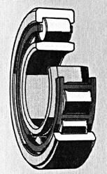
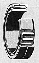
100 4 Standard Wheels Pros: Simpler than 6 wheel Lighter than 6 wheels Cheaper than 6 wheels All weight supported by drive wheels Resistant to being pushed Cons Turning! (keep wheel base short) Can high center during climbs Bigger wheels = higher COG

101 4 Wheels With Omni Wheels Pros: Same as basic four wheel Turns like a dream but not around the robot center Cons: Vulnerable to being pushed on the side when bumping into objects Traction may not be as high as 4 standard wheels


102 6 Wheels Pros: Great traction under most circumstances Smaller wheels Smaller sprockets = weight savings Turns around robot center Can t be easily high centered Resistant to being pushed Cons: Weight More complex chain paths Chain tensioning can be fun More expensive

103 Six Wheel Variants
 Redundancy Turns around robot center Cons: Lower traction Can high center")

104 Mecanum Pros: Highly maneuverable Might reduce complexity elsewhere in robot Simple Chain Paths (or no chain) Redundancy Turns around robot center Cons: Lower traction Can high center Not great for climbing or pushing Software complexity Drift dependant on weight distribution Shifting transmissions impractical Autonomous challenging More driver practice necessary Expensive

105 Holonomic Drive


106 Treads Pros: Great traction Turns around robot center Super at climbing Resistant to being pushed Looks awesome! Cons Not as energy efficient High mechanical complexity Difficult for student-built teams to make Needs a machine shop or buy them Turns can tear the tread off and/or stall motors

107 Swerve/Crab Wheels steer independently or as a set More traction than Mecanum Mechanically Complex! Adds weight

108


109 Bearings Two Common Types Bushings - simple, cheap, limited life, porous material such as Oilite which holds oil like a sponge Rolling Element support axial or radial loading, long life, grease or oil-filled, various types of seals, readily available from standard product catalogs, ex. ball bearings


110 Roller Bearings Needle Roller Tapered Roller Spherical Roller

111 Rolling Element Bearing Parts Outer Race Inner Race The parts and nomenclature for a Ball Bearing Bore Ball Cage or Separator
112 Bearings -continued Hydrodynamic or Sleeve - oil filled, no wear, radial or thrust, common in automobile engines (e.g., crankshaft bearings) Rotating Shaft Sleeve Bearing Shaft Rides On Oil Wedge Oil Filled Cavity A typical radial clearance is on the order of.010
113 END
GEAR CONTENTS POWER TRANSMISSION GEAR TYPES OF GEARS NOMENCLATURE APPLICATIONS OF GEARS VELOCITY RATIO GEAR TRAINS EXAMPLE PROBLEMS AND QUESTIONS
 GEAR CONTENTS POWER TRANSMISSION GEAR TYPES OF GEARS NOMENCLATURE APPLICATIONS OF GEARS VELOCITY RATIO GEAR TRAINS EXAMPLE PROBLEMS AND QUESTIONS GEAR.. Power transmission is the movement of energy from
What is a Mechanism?
 Mechanisms What is a Mechanism? A mechanism is the part of a machine which contains two or more pieces arranged so that the motion of one compels the motion of the others. Generally used to: Change the
Graphical representation of a gear
 Homework 4 Gears Gears are designed to transmit rotary motion. Often they are arranged in a gear train (meshed together). Gear trains provide a change in speed, torque (turning force) and direction (clockwise
How to Build with the Mindstorm Kit
 How to Build with the Mindstorm Kit There are many resources available Constructopedias Example Robots YouTube Etc. The best way to learn, is to do Remember rule #1: don't be afraid to fail New Rule: don't
Chapter 3. Transmission Components
 Chapter 3. Transmission Components The difference between machine design and structure design An important design problem in a mechanical system is how to transmit and convert power to achieve required
Introduction. Kinematics and Dynamics of Machines. Involute profile. 7. Gears
 Introduction The kinematic function of gears is to transfer rotational motion from one shaft to another Kinematics and Dynamics of Machines 7. Gears Since these shafts may be parallel, perpendicular, or
Driver Driven. InputSpeed. Gears
 Gears Gears are toothed wheels designed to transmit rotary motion and power from one part of a mechanism to another. They are fitted to shafts with special devices called keys (or splines) that ensure
(POWER TRANSMISSION Methods)
") UNIT-5 (POWER TRANSMISSION Methods) It is a method by which you can transfer cyclic motion from one place to another or one pulley to another pulley. The ways by which we can transfer cyclic motion are:-
UNIT-5 (POWER TRANSMISSION Methods) It is a method by which you can transfer cyclic motion from one place to another or one pulley to another pulley. The ways by which we can transfer cyclic motion are:-
TECHNOLOGY MECHANISMS
 TECHNOLOGY MECHANISMS 3º ESO IES CHAN DO MONTE URTAZA 1 WHAT IS A MECHANISM? Mechanism are devices that have been designed to make jobs easier. They all have certain things in common: They involve some
12/6/2013 9:09 PM. Chapter 13. Gears General. Dr. Mohammad Suliman Abuhaiba, PE
 Chapter 13 Gears General 1 2 Chapter Outline 1. Types of Gears 2. Nomenclature 3. Conjugate Action 4. Involute Properties 5. Fundamentals 6. Contact Ratio 7. Interference 8. The Forming of Gear Teeth 9.
KINEMATICS OF MACHINARY UBMC302 QUESTION BANK UNIT-I BASICS OF MECHANISMS PART-A
 KINEMATICS OF MACHINARY UBMC302 QUESTION BANK UNIT-I BASICS OF MECHANISMS PART-A 1. Define the term Kinematic link. 2. Classify kinematic links. 3. What is Mechanism? 4. Define the terms Kinematic pair.
1/2/2015 2:04 PM. Chapter 13. Gears General. Dr. Mohammad Suliman Abuhaiba, PE
 Chapter 13 Gears General 1 2 Chapter Outline 1. Types of Gears 2. Nomenclature 3. Conjugate Action 4. Involute Properties 5. Fundamentals 6. Contact Ratio 7. Interference 8. The Forming of Gear Teeth 9.
CHAPTER 6 GEARS CHAPTER LEARNING OBJECTIVES
 CHAPTER 6 GEARS CHAPTER LEARNING OBJECTIVES Upon completion of this chapter, you should be able to do the following: Compare the types of gears and their advantages. Did you ever take a clock apart to
Chapter 8 Kinematics of Gears
 Chapter 8 Kinematics of Gears Gears! Gears are most often used in transmissions to convert an electric motor s high speed and low torque to a shaft s requirements for low speed high torque: Speed is easy
Part VII: Gear Systems: Analysis
 Part VII: Gear Systems: Analysis This section will review standard gear systems and will provide the basic tools to perform analysis on these systems. The areas covered in this section are: 1) Gears 101:
UNIT -I. Ans: They are specified by the no. of strands & the no. of wires in each strand.
 VETRI VINAYAHA COLLEGE OF ENGINEERING AND TECHNOLOGY, THOTTIAM, NAMAKKAL-621215. DEPARTMENT OF MECHANICAL ENGINEERING SIXTH SEMESTER / III YEAR ME6601 DESIGN OF TRANSMISSION SYSTEM (Regulation-2013) UNIT
Lecture (7) on. Gear Measurement. By Dr. Emad M. Saad. Industrial Engineering Dept. Faculty of Engineering. Fayoum University.
 on. Gear Measurement. By Dr. Emad M. Saad. Industrial Engineering Dept. Faculty of Engineering. Fayoum University.") 1 Lecture (7) on Gear Measurement Fayoum University By Dr. Emad M. Saad Industrial Engineering Dept. Faculty of Engineering Fayoum University Faculty of Engineering Industrial Engineering Dept. 2015-2016
1 Lecture (7) on Gear Measurement Fayoum University By Dr. Emad M. Saad Industrial Engineering Dept. Faculty of Engineering Fayoum University Faculty of Engineering Industrial Engineering Dept. 2015-2016
Code No: R Set No. 1
 Code No: R05310304 Set No. 1 III B.Tech I Semester Regular Examinations, November 2007 KINEMATICS OF MACHINERY ( Common to Mechanical Engineering, Mechatronics, Production Engineering and Automobile Engineering)
2. a) What is pantograph? What are its uses? b) Prove that the peaucellier mechanism generates a straight-line motion. (5M+10M)
 What is pantograph? What are its uses? b) Prove that the peaucellier mechanism generates a straight-line motion. (5M+10M)") Code No: R22032 R10 SET - 1 1. a) Define the following terms? i) Link ii) Kinematic pair iii) Degrees of freedom b) What are the inversions of double slider crank chain? Describe any two with neat sketches.
Code No: R22032 R10 SET - 1 1. a) Define the following terms? i) Link ii) Kinematic pair iii) Degrees of freedom b) What are the inversions of double slider crank chain? Describe any two with neat sketches.
ME6601 DESIGN OF TRANSMISSION SYSTEMS
 SYED AMMAL ENGINEERING COLLEGE (Approved by the AICTE, New Delhi, Govt. of Tamilnadu and Affiliated to Anna University, Chennai) Established in 1998 - An ISO 9001:2008 Certified Institution Dr. E.M.Abdullah
Transmission systems: Multiple components that have the same type of movement (rotational, linear, etc)
") Transmission systems: Multiple components that have the same type of movement (rotational, linear, etc) Transformation systems: Different components in the system have different types of movement Ex: rotational
Transmission systems: Multiple components that have the same type of movement (rotational, linear, etc) Transformation systems: Different components in the system have different types of movement Ex: rotational
MECHANISM: TRANSMISSION THE TYPE OF INPUT MOVEMENT IS THE SAME AS THE OUTPUT TRANSFORMATION THE MECHANISM TRANSFORMS THE TYPE OF MOVEMENT
 MECHANISM: The mechanisms are elements intended to transmit and transform forces and movements from an INPUT element (motor) to an OUTPUT element. Types of movements: Rotary Motion -this is motion in a
ME6401 KINEMATICS OF MACHINERY UNIT- I (Basics of Mechanism)
") ME6401 KINEMATICS OF MACHINERY UNIT- I (Basics of Mechanism) 1) Define resistant body. 2) Define Link or Element 3) Differentiate Machine and Structure 4) Define Kinematic Pair. 5) Define Kinematic Chain.
ME6401 KINEMATICS OF MACHINERY UNIT- I (Basics of Mechanism) 1) Define resistant body. 2) Define Link or Element 3) Differentiate Machine and Structure 4) Define Kinematic Pair. 5) Define Kinematic Chain.
MANUAL TRANSMISSION SERVICE
 MANUAL TRANSMISSION SERVICE Introduction Internal combustion engines develop very little torque or power at low rpm. This is especially obvious when you try to start out in direct drive, 4th gear in a
Simple Gears and Transmission
 Simple Gears and Transmission Simple Gears and Transmission page: of 4 How can transmissions be designed so that they provide the force, speed and direction required and how efficient will the design be?
MECHANISMS. AUTHORS: Santiago Camblor y Pablo Rivas INDEX
 MECHANISMS AUTHORS: Santiago Camblor y Pablo Rivas INDEX 1 INTRODUCTION 2 LEVER 3 PULLEYS 4 BELT AND PULLEY SYSTEM 5 GEARS 6 GEARS WITH CHAIN 7 WORM GEAR 8 RACK AND PINION 9 SCREW AND NUT 10 CAM 11 ECCENTRIC
Mechanisms. Prepared by Juan Blázquez, Alissa Gildemann
 Unit 9 Mechanisms 1. Mechanisms Mechanisms are devices that transmit and convert forces and motions from an input to an output element. They enable us to use less effort to carry out a task. We can classify
Moments. It doesn t fall because of the presence of a counter balance weight on the right-hand side. The boom is therefore balanced.
 Moments The crane in the image below looks unstable, as though it should topple over. There appears to be too much of the boom on the left-hand side of the tower. It doesn t fall because of the presence
Simple Gears and Transmission
 Simple Gears and Transmission Contents How can transmissions be designed so that they provide the force, speed and direction required and how efficient will the design be? Initial Problem Statement 2 Narrative
LEGO Parts Guide. Naming and Building with LEGO parts. Version 1.3 4/12/10
 LEGO Parts Guide Naming and Building with LEGO parts Version 1.3 4/12/10 Table of Contents Connectors... 4 Friction Pegs... 4 Frictionless Pegs... 5 Ball Joints / Tie Rods... 6 Bushings... 7 Angle Connectors...
Basic Fundamentals of Gear Drives
 Basic Fundamentals of Gear Drives Course No: M06-031 Credit: 6 PDH A. Bhatia Continuing Education and Development, Inc. 9 Greyridge Farm Court Stony Point, NY 10980 P: (877) 322-5800 F: (877) 322-4774
Mechanism Feasibility Design Task
 Mechanism Feasibility Design Task Dr. James Gopsill 1 Contents 1. Last Week 2. Types of Gear 3. Gear Definitions 4. Gear Forces 5. Multi-Stage Gearbox Example 6. Gearbox Design Report Section 7. This Weeks
Chapter seven. Gears. Laith Batarseh
 Chapter seven Gears Laith Batarseh Gears are very important in power transmission between a drive rotor and driven rotor What are the functions of gears? - Transmit motion and torque (power) between shafts
Model Library Power Transmission
 Model Library Power Transmission The Power Transmission libraries in SimulationX support the efficient modeling and analysis of mechanical powertrains as well as the simulation-based design of controlled
Instantaneous Centre Method
 Instantaneous Centre Method The combined motion of rotation and translation of the link AB may be assumed to be a motion of pure rotation about some centre I, known as the instantaneous centre of rotation.
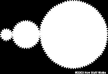
Gear Drives. A third gear added to the system will rotate in the same direction as the drive gear Equal diameters = Equal number of teeth = Same speed
 Gear Drive Systems Gear Drives Gear Drive: Synchronous mechanical drive that uses gears to transfer power Gear: A toothed wheel that meshes with other toothed wheels to transfer rotational power Pinion
Mechanical Power Transmission. September 16, 2008
 2008 TE Sessions Supported by Mechanical Power Transmission September 16, 2008 www.robojackets.org Goals Hand out kits to teams that don t have one. More physics concepts and terms Understanding key devices
CH#13 Gears-General. Drive and Driven Gears 3/13/2018
 CH#13 Gears-General A toothed wheel that engages another toothed mechanism in order to change the speed or direction of transmitted motion The gear set transmits rotary motion and force. Gears are used
Gear Tooth Geometry - This is determined primarily by pitch, depth and pressure angle
 Gear Tooth Geometry - This is determined primarily by pitch, depth and pressure angle Addendum: The radial distance between the top land and the pitch circle. Addendum Circle: The circle defining the outer
11/23/2013. Chapter 13. Gear Trains. Dr. Mohammad Suliman Abuhiba, PE
 Chapter 13 Gear Trains 1 2 13.2. Types of Gear Trains 1. Simple gear train 2. Compound gear train 3. Reverted gear train 4. Epicyclic gear train: axes of shafts on which the gears are mounted may move
Spur Gears. Helical Gears. Bevel Gears. Worm Gears
 Spur s General: Spur gears are the most commonly used gear type. They are characterized by teeth which are perpendicular to the face of the gear. Spur gears are by far the most commonly available, and
St.MARTIN S ENGINEERING COLLEGE Dhulapally, Secunderabad
 St.MARTIN S ENGINEERING COLLEGE Dhulapally, Secunderabad-500 014 Subject: Kinematics of Machines Class : MECH-II Group A (Short Answer Questions) UNIT-I 1 Define link, kinematic pair. 2 Define mechanism
All levers are one of three types, usually called classes. The class of a lever depends on the relative position of the load, effort and fulcrum:
 Página 66 de 232 Mechanisms A mechanism is simply a device which takes an input motion and force, and outputs a different motion and force. The point of a mechanism is to make the job easier to do. The
NEXEN WHITEPAPER. Nexen Group, Inc. 560 Oak Grove Parkway / Vadnais Heights, MN /
 NEXEN WHITEPAPER Roller Versatility, Pinion Precision Systemand Short Lead Times: The CRD MR Rotary Indexer Nexen s new indexer is a cost-effective solution for automating a wide variety of tasks. Whether
What are the functions of gears? What is gear?
 8//0 hapter seven Laith atarseh are very important in power transmission between a drive rotor and driven rotor What are the functions of gears? - Transmit motion and torque (power) between shafts - Maintain
Marine Engineering Exam Resource Review of Couplings
 1. What are rigid couplings used for? Used to join drive shafts together. True alignment and rigidity are required. Example Drive shafts and production lines, bridge cranes, solid shaft that needs to be
11. GEAR TRANSMISSIONS
 11. GEAR TRANSMISSIONS 11.1. GENERAL CONSIDERATIONS Gears are one of the most important elements used in machinery. There are few mechanical devices that do not have the need to transmit power and motion
SECTION 8 BEVEL GEARING
 SECTION 8 BEVEL GEARING For intersecting shafts, bevel gears offer a good means of transmitting motion and power. Most transmissions occur at right angles, Figure 8-1, but the shaft angle can be any value.
KINGS COLLEGE OF ENGINEERING DEPARTMENT OF MECHANICAL ENGINEERING
 KINGS COLLEGE OF ENGINEERING DEPARTMENT OF MECHANICAL ENGINEERING QUESTION BANK Sub Code/Name: ME 1352 DESIGN OF TRANSMISSION SYSTEMS Year/Sem: III / VI UNIT-I (Design of transmission systems for flexible
Copyright Notice. Small Motor, Gearmotor and Control Handbook Copyright Bodine Electric Company. All rights reserved.
 Copyright Notice Small Motor, Gearmotor and Control Handbook Copyright 1993-2003 Bodine Electric Company. All rights reserved. Unauthorized duplication, distribution, or modification of this publication,
What Are Gears? What Do They Do?
 What Are Gears? What Do They Do? Pre-Lesson Quiz 1. What is a gear? 2. List as many examples as you can of gears or objects that use gears. 2 Pre-Lesson Quiz Answers 1. What is a gear? A gear is a wheel
 VALLIAMMAI ENGINEERING COLLEGE DEPARTMENT OF MECHANICAL ENGINEERING ME6401- KINEMATICS OF MACHINERY QUESTION BANK PART-A Unit 1-BASICS OF MECHANISMS 1. Define degrees of freedom. BT1 2. Describe spatial
Question 8 Engineering Higher Level
 Rack and Pinion Rotary motion to linear motion As pinion rotates, gear teeth mesh with those on rack Applications: Lowering table on pillar drill ; Steering in Car Worm and Worm wheel Transmits power through
 DEPARTMENT OF MECHANICAL ENGINEERING Subject code: ME6601 Subject Name: DESIGN OF TRANSMISSION SYSTEMS UNIT-I DESIGN OF TRANSMISSION SYSTEMS FOR FLEXIBLE ELEMENTS 1. What is the effect of centre distance
 DEPARTMENT OF MECHANICAL ENGINEERING ME6401- KINEMATICS OF MACHINERY QUESTION BANK Part-A Unit 1-BASICS OF MECHANISMS 1. Define degrees of freedom. 2. What is meant by spatial mechanism? 3. Classify the
CHENDU COLLEGE OF ENGINEERING & TECHNOLOGY DEPARTMENT OF MECHANICAL ENGINEERING QUESTION BANK IV SEMESTER
 CHENDU COLLEGE OF ENGINEERING & TECHNOLOGY DEPARTMENT OF MECHANICAL ENGINEERING QUESTION BANK IV SEMESTER Sub Code: ME 6401 KINEMATICS OF MACHINERY UNIT-I PART-A 1. Sketch and define Transmission angle
Wheeled Mobile Robots
 Wheeled Mobile Robots Most popular locomotion mechanism Highly efficient on hard and flat ground. Simple mechanical implementation Balancing is not usually a problem. Three wheels are sufficient to guarantee
Chain Drives. Pitch. Basic Types -There are six major types of power-
 1 2 Power transmission chains have two things in common; side bars or link plates, and pin and bushing joints. The chain articulates at each joint to operate around a toothed sprocket. The pitch of the
Introduction to Gear Design
 Introduction to Gear Design Course No: M03-016 Credit: 3 PDH Robert P. Tata, P.E. Continuing Education and Development, Inc. 9 Greyridge Farm Court Stony Point, NY 10980 P: (877) 322-5800 F: (877) 322-4774
Robot components: Actuators
 Robotics 1 Robot components: Actuators Prof. Alessandro De Luca Robotics 1 1 Robot as a system program of tasks commands Robot actions working environment mechanical units supervision units sensor units
The Life of a Lifter, Part 2
 Basics Series: The Life of a Lifter, Part 2 -Greg McConiga Last time we looked at some complicated dynamics and compared flats to rollers. Now for the hands-on. 6 FEATURE This off-the-shelf hydraulic lifter
GEARBOXES. Gearboxes. Gearboxes. Gearbox is a mechanical device utilized to increase the output torque or change
 GEARBOXES Gearboxes Gearboxes Gearbox is a mechanical device utilized to increase the output torque or change the speed of a motor. The motor's shaft is attached to one end of the gearbox and through the
Purposes of a Drive Axle Assembly
 Differentials Purposes of a Drive Axle Assembly To transmit power from the drive shaft to the wheels To turn the power flow 90 degrees on RWD cars To allow the wheels to turn at different speeds while
If the windlass has a diameter of 300mm, calculate the torque produced by the load. (Show all working and units.)
") 8. A winch system used to raise a 5N load is shown. (a) If the windlass has a diameter of mm, calculate the torque produced by the load. (Show all working and units.) T = r = 5 5 = 875Nmm = 8. 75Nm substitution
8. A winch system used to raise a 5N load is shown. (a) If the windlass has a diameter of mm, calculate the torque produced by the load. (Show all working and units.) T = r = 5 5 = 875Nmm = 8. 75Nm substitution
1. (a) Discuss various types of Kinematic links with examples. (b) Explain different types of constrained motions with examples.
 Discuss various types of Kinematic links with examples. (b) Explain different types of constrained motions with examples.") Code No: RR310304 Set No. 1 III B.Tech I Semester Supplementary Examinations, February 2007 KINEMATICS OF MACHINERY ( Common to Mechanical Engineering, Mechatronics and Production Engineering) Time: 3
Code No: RR310304 Set No. 1 III B.Tech I Semester Supplementary Examinations, February 2007 KINEMATICS OF MACHINERY ( Common to Mechanical Engineering, Mechatronics and Production Engineering) Time: 3
Gearheads H-51. Gearheads for AC Motors H-51
 Technical Reference H-51 for AC Since AC motor gearheads are used continuously, primarily for transmitting power, they are designed with priority on ensuring high permissible torque, long life, noise reduction
Friction Management Solutions for Industrial Gear Drives
 Friction Management Solutions for Industrial Gear Drives A complete range of bearings and complementary services help the gear drive industry to meet ever-increasing requirements in product reliability
Power Transmission Elements II: Gears and Bearings. Lecture 3, Week 4
 Power Transmission Elements II: Gears and Bearings Lecture 3, Week 4 Announcements Lab 4 need to finish by Friday Friday lab can get started today Project proposal Due at 23:59 tonight Email to us: matthewg@mit.edu,
Unit IV GEARS. Gallery
 Gallery Components of a typical, four stroke cycle, DOHC piston engine. (E) Exhaust camshaft, (I) Intake camshaft, (S) Spark plug, (V) Valves, (P) Piston, (R) Connecting rod, (C) Crankshaft, (W) Water
Bearings. Rolling-contact Bearings
 Bearings A bearing is a mechanical element that limits relative motion to only the desired motion and at the same time it reduces the frictional resistance to the desired motion. Depending on the design
BRCM COLLEGE OF ENGINEERING & TECHNOLOGY BAHAL, BHIWANI Practical Experiment Instructions Sheet
 BRCM COLLEGE OF KOM ME- 212 F KINEMATICS OF MACHINES LAB BRANCH-ME List of Experiments : 1. To study various types of Kinematic links, pairs, chains and Mechanisms. 2. To study inversions of 4 Bar Mechanisms,
Mechanics and Mechanisms. What is do you think about when you hear the word mechanics? Mechanics. Is this a mechanism? 2/17/2011
 Mechanics and Mechanisms What is do you think about when you hear the word mechanics? Mechanics Mechanics is the study of how things move Is this a mechanism? Concerned with creating useful movement through
Product design: Mechanical systems
 Product design: Mechanical systems Recall Mechanisms can: change direction of movement, e.g. from clockwise to anticlockwise or from horizontal to vertical; change type of movement, e.g. from rotating
High Tech High Top Hat Technicians. Gearbox Design as Seen Through the Toughbox. Gear Up
 High Tech High Top Hat Technicians Gearbox Design as Seen Through the Toughbox Or Gear Up Toughbox Gear Pairs Diametral Pitch (DP): 20 per inch Pressure angle: 14.5 degrees Gear Teeth 14 50 16 48 19 45
Drive Systems. Steve Shade October 26, 2013
 Steve Shade October 26, 2013 Introduction Steve Shade 15 year veteran Chesapeake Team Development Lead Chesapeake Head Referee Senior Controls and Simulation Engineer for Rolls-Royce Marine North America
Axles & Differentials
 ATASA 5 th Study Guide Chapter 39 Pages 1138 1172 60 Points Please Read The Summary Before We Begin Keeping in mind the Career Cluster of Transportation, Distribution & Logistics Ask yourself: What TDL
1.6 Features of common gears
 1.6 Features of common gears Chapter 1.2 covered briefly on types of gear. The main gear features are explained here. Helical gear Helical gear has characteristics of transferability of larger load, less
Mechanical Motion. Control Components. and Subsystems. Understanding How Components Effect System Performance
 Mechanical Motion Control Components and Subsystems Understanding How Components Effect System Performance Mechanical Motion Control Components and Subsystems Overview: Bearings Linear Bearing Technologies
UNIT III TRANSMISSION SYSTEMS CONTENTS: Clutch-types and construction Gear boxes- manual and automatic Gear shift mechanisms Over drive Transfer box
 UNIT III TRANSMISSION SYSTEMS CONTENTS: Clutch-types and construction Gear boxes- manual and automatic Gear shift mechanisms Over drive Transfer box Fluid flywheel Torque converter Propeller shaft Slip
TYPICAL EXPERIMENTS Centers of gravity. Force triangle. Force polygon and Bow s Notation. Non- concurrent forces.
 MM 500-001 BASIC PANEL The panel is made from a perforated stainless steel sheet mounted on two supports with adjustable footings. The panel can be tilted, put in portrait or landscape position. Accessories
The Available Solution CYCLO DRIVE. Gearmotors & Speed Reducers. Series
 The Available Solution CYCLO DRIVE Gearmotors & Speed Reducers 6000 Series WHAT DO YOU THINK OF THIS? THESE ARE THE ADVANTAGES OF THE NEWEST CYCLO, 6000 SERIES: More frame sizes, gear ratios and motor
NuVinci Planetary Analogy
 NuVinci Planetary Analogy 2012 Fallbrook Technologies Inc. All rights reserved. Slide 1 Discussion of Planetary Analogy An ordinary planetary gear has three components: A ring gear A sun gear A carrier
Catalog Q Conversion For those wishing to ease themselves into working with metric gears
 1.3.4 Conversion For those wishing to ease themselves into working with metric gears by looking at them in terms of familiar inch gearing relationships and mathematics, Table 1-5 is offered as a means
Moon Transmission Systems. Def: System has one type of movement rotaon
 Moon Transmission Systems Def: System has one type of movement rotaon Made up of: Driver: Iniates the moon Driven: Receives the moon Intermediate: Found between driver and driven Driver component Driven
Sheet 1 Variable loading
 Sheet 1 Variable loading 1. Estimate S e for the following materials: a. AISI 1020 CD steel. b. AISI 1080 HR steel. c. 2024 T3 aluminum. d. AISI 4340 steel heat-treated to a tensile strength of 1700 MPa.
Gear Engineering Data. Spur Gear Gear Formulas Drive Selection Horsepower and Torque Tables
 Engineering Gear Engineering Data Spur Gear Gear Formulas Drive Selection Horsepower and Torque Tables G-79 Gear Selection Stock Spur Gear Drive Selection When designing a stock gear drive using the horsepower
INDEX. 414 Agitator reversing mechanism which varies point of reversal. 250 Alternate and intermittent drive for two shafts
 INDEX Agitating device for pin hopper.----------------------------------------- 414 Agitator reversing mechanism which varies point of reversal. 250 Alternate and intermittent drive for two shafts.-----.----------.--..--
Robot components: Actuators
 Robotics 1 Robot components: Actuators Prof. Alessandro De Luca Robotics 1 1 Robot as a system program of tasks commands Robot actions working environment mechanical units supervision units sensor units
1 135 teeth to rack
 1. A spur gear with 46 teeth, 2.5 module has to be cut on a column and knee type horizontal milling machine with a rotary disc type form gear milling cutter. The 2.5 module cutter no. 3 is used on a blank
MECHANICAL DRIVES 1 SPUR GEAR DRIVES LEARNING ACTIVITY PACKET BB502-XD06AEN
 MECHANICAL DRIVES 1 LEARNING ACTIVITY PACKET SPUR GEAR DRIVES BB502-XD06AEN LEARNING ACTIVITY PACKET 6 SPUR GEAR DRIVES INTRODUCTION This LAP will begin the study of the third type of adjacent shaft-to-shaft
PRODUCT OVERVIEW HIGHEST PRECISION
 PRODUCT OVERVIEW If you need high precision gear reducers at a reasonable cost and you value innovation and excellent service, take a close look at our product line. You ll find a wide range of products
ME3200Practice Questions
 ME3200Practice Questions 5.(15 pts) esign an active low-pass filter with a gain of 5 and a time constant of 50 msec. Use realistic values as were used in lab. 6. (8 pts) A pressure sensor is made by gluing
M3 Design Product Teardown Kobalt Double-Drive Screwdriver
 19 Jun, 2013 Why do the product teardowns? M3 Design Product Teardown Kobalt Double-Drive Screwdriver Part of the product development process is to apply knowledge gained from prior experience during the
Theory of Machines. CH-1: Fundamentals and type of Mechanisms
 CH-1: Fundamentals and type of Mechanisms 1. Define kinematic link and kinematic chain. 2. Enlist the types of constrained motion. Draw a label sketch of any one. 3. Define (1) Mechanism (2) Inversion
Changes in direction.! Using pulleys with belts
 Mechanisms Changes in direction! Using pulleys with belts Changes in direction! Using friction wheels Changes in direction! Using gears Worm drive! Reduces the speed! It is non-reversible Worm drive! Multiple
FIRSTRANKER. 2. (a) Distinguish (by neat sketches) betweenpeaucellier mechanism and Hart mechanism.
 Distinguish (by neat sketches) betweenpeaucellier mechanism and Hart mechanism.") Code No: 07A51404 R07 Set No. 2 IIIB.Tech I Semester Examinations,May 2011 KINEMATICS OF MACHINERY Mechatronics Time: 3 hours Max Marks: 80 Answer any FIVE Questions All Questions carry equal marks 1.
Code No: 07A51404 R07 Set No. 2 IIIB.Tech I Semester Examinations,May 2011 KINEMATICS OF MACHINERY Mechatronics Time: 3 hours Max Marks: 80 Answer any FIVE Questions All Questions carry equal marks 1.
Lectures on mechanics
 Lectures on mechanics (lesson #3) francesco.becchi@telerobot.it LESSONS TIME TABLE (pls. take note) 28/11 h9/12- mech components 1 (3h) 4/12 h9/12 mech components 2 (3h) 11/12 h9/12 mech technologies (3h)
Shifting gears: simplify your design with slewing ring bearings
 White Paper Shifting gears: simplify your design with slewing ring bearings Scott Hansen, VP, Manufacturing Planning, Kaydon Bearings, an SKF Group company A slewing ring bearing has rolling elements designed
STEERING SYSTEM Introduction
 STEERING SYSTEM Introduction The steering makes it possible to change direction. The steering must be reliable and safe; there must not be too much play in the steering. It must be possible to steer accurately.
INTRODUCTION TO DRIVETRAINS
 Chapter3 INTRODUCTION TO DRIVETRAINS OBJECTIVES After studying Chapter 3, the reader should be able to: 1. Identify the major components of an automotive drivetrain. 2. Describe the purpose of the major