Design & Development of Precision Plastic Gear Transmissions
|
|
|
- Duane Leslie Cannon
- 5 years ago
- Views:
Transcription


1 Design & Development of Precision Plastic Gear Transmissions David Sheridan Senior Design Engineer TICONA Ticona Gears Webinar Gear_DesignPPT_AM_0212_016.pdf
2 Overview Methodical and rational procedure for designing and developing high-precision injection-molded plastic gear transmissions that function satisfactorily across the entire range of manufacturing tolerances and operating conditions. Calculations to examine the effects of tolerances and environmental influences on gear geometry, operating center distance, and gear performance Ticona Gears Webinar Gear_DesignPPT_AM_0212_016.pdf
3 Outline 1. Why plastics for gears 2. Gear types and arrangements for plastics 3. Design and engineering 4. Specifications 5. Prototype parts and mold development 6. Measurement and inspection 7. Testing and validation 8. Production molding Ticona Gears Webinar Gear_DesignPPT_AM_0212_016.pdf


4 Plastic vs. Metal Gears Plastic Advantages Lower cost Injection molding vs. machining Especially for large quantities As-molded, no finishing Greater design flexibility Parts consolidation Molded-in features Allow other gear geometries Easy to mold, difficult to machine, e.g., internal and cluster gears Less noise Lower modulus Do not transmit sound Greater tooth deflection increases load sharing and reduces transmission error effects Light weight, low inertia Reduce dynamic loading and noise Ticona Gears Webinar Gear_DesignPPT_AM_0212_016.pdf


5 Plastic vs. Metal Gears Plastic Advantages Inherent lubricity Do not need lubrication in many low-load applications Internal lubricants For applications that cannot use external lubricants Computer printers Motorized toys Chemical and corrosion resistance External lubricants Grease Oil Water Lawn sprinklers Water meters Shower heads Ticona Gears Webinar Gear_DesignPPT_AM_0212_016.pdf
6 Outline 1. Why plastics for gears 2. Gear types and arrangements for plastics 3. Design and engineering 4. Specifications 5. Prototype parts and mold development 6. Measurement and inspection 7. Testing and validation 8. Production molding Ticona Gears Webinar Gear_DesignPPT_AM_0212_016.pdf
7 Involute Gearing Involute Curve Taut String Base Circle Ticona Gears Webinar Gear_DesignPPT_AM_0212_016.pdf
8 Involute Gearing Advantages of Involute Gear Teeth Provide constant angular velocity (or ratio) between two gears conjugate action Conjugate action is independent of changes in center distance (CD) design flexibility insensitive to manufacturing tolerances, material expansion and contraction Manufacturing ease and accuracy with basic rack Conjugate Action Independent of CD Ticona Gears Webinar Gear_DesignPPT_AM_0212_016.pdf
9 Gear Types and Arrangements Parallel Axis Spur Helical External or Internal Non-Parallel Intersecting Axis Bevel, On-Center Face, On-Center Non-Intersecting Axis Worms Bevel, Off-Center Face, Off-Center Ticona Gears Webinar Gear_DesignPPT_AM_0212_016.pdf


10 Straight Bevel Gears Dudley Critical on Mounting and Alignment Ticona Gears Webinar Gear_DesignPPT_AM_0212_016.pdf


11 Face Gears Not critical on center distance Not critical on axial position Dudley Recommended for Plastics Ticona Gears Webinar Gear_DesignPPT_AM_0212_016.pdf
12 Worm Gearing Characteristics High ratio Low part count Low cost Low noise Low capacity Types of Worm Gears Involute worm (crossed-helical) Worm thread profile straight in axial plane Worm thread profile straight in normal plane Worm produced by conical mill or grinding wheel with straight sides These are NOT interchangeable! Ticona Gears Webinar Gear_DesignPPT_AM_0212_016.pdf


13 Worm Gearing Singleenveloping Doubleenveloping Semienveloping Cylindrical Dudley Critical on Mounting and Alignment Ticona Gears Webinar Gear_DesignPPT_AM_0212_016.pdf

14 Crossed-Helical Involute Gears Not critical on center distance Not critical on axial position Theoretical POINT contact Useful for low power low cost low noise Recommended for Plastic Worm Gearing Ticona Gears Webinar Gear_DesignPPT_AM_0212_016.pdf
15 Gear Types and Arrangements Parallel Axis Spur Helical External or Internal Epicyclics Non-Parallel Intersecting Axis Bevel, On-Center Face, On-Center Non-Intersecting Axis Worms Bevel, Off-Center Face, Off-Center Ticona Gears Webinar Gear_DesignPPT_AM_0212_016.pdf
16 Epicyclic Drives Epicyclic Arrangements Simple epicyclics Multi-stage epicyclics Compound epicyclics Coupled epicyclics Fixed differentials Characteristics Large reductions High power density Small space Split power path Simple Epicyclics Planetary Star Sun Input Output Simple Planetary Ticona Gears Webinar Gear_DesignPPT_AM_0212_016.pdf Dudley
17 Relative Gear Train Size 15:1 Reduction Single Reduction 100% ( f d 2 ) Double Reduction Single Branch 40% Double Reduction Double Branch 25% 2-Stage Planetary 9.5% Ticona Gears Webinar Gear_DesignPPT_AM_0212_016.pdf
18 Outline 1. Why plastics for gears 2. Gear types and arrangements for plastics 3. Design and engineering 4. Specifications 5. Prototype parts and mold development 6. Measurement and inspection 7. Testing and validation 8. Production molding Ticona Gears Webinar Gear_DesignPPT_AM_0212_016.pdf

19 Gear Noise Influence of Gear Quality 56.8dB 61.1dB 58.3dB 68.5dB Low Noise Gears High Large Noise Gears Ticona Gears Webinar Gear_DesignPPT_AM_0212_016.pdf
20 The Plastic Gear Development Team Project Engineer Molder Manufacturing Engineer Tool Builder Gear Engineer Purchasing Material Supplier Plastics Engineer Quality Control Engineer Ticona Gears Webinar Gear_DesignPPT_AM_0212_016.pdf
21 Plastic Gear Development Identify Application Voice of the Customer (VOC) Define Operating Requirements Prime mover Torque and speed Inertia, natural freq. Load(s) Torque and speed Special conditions Inertia, natural freq. Duty cycle Life Physical limits Ratio Precision Efficiency Lubrication Environment Temperature Chemical exposure Moisture exposure Test requirements Other Anticipate Future Applications Ticona Gears Webinar Gear_DesignPPT_AM_0212_016.pdf Gears-007r1 EN 12/11

22 Select Overall Transmission Geometry From requirements Minimum weight? Minimum size? Good plastic designs may use more gears with split power path Carefully consider added features Runout Distortion Shafting and bearings Precision Efficiency Housing considerations Stiffness Tolerances Ticona Gears Webinar Gear_DesignPPT_AM_0212_016.pdf

23 Preliminary Gear Sizing Select materials Select preliminary gear geometry Number of teeth Size (pitch or module) Profile (tooth proportions) Nominal ambient conditions Simple load analysis K-factor Unit load Ticona Gears Webinar Gear_DesignPPT_AM_0212_016.pdf For more information see ANSI/AGMA 1106-A97, Tooth Proportions for Plastic Gears

24 Select Materials Suit operating environment Temperature range Dimensional behavior Property behavior Chemical environment Dimensional behavior Property behavior Appropriate property mix Fatigue Stiffness Impact Creep Interaction with other components Friction Wear For more information see AGMA 920-A01, Materials for Plastic Gears Ticona Gears Webinar Gear_DesignPPT_AM_0212_016.pdf
25 Determine Production Tolerances Gears Diameters and tolerances Tooth thickness and tolerance Tip radius and tolerance Accuracy grade Housing Center distance and tolerance Shafts, bearings, and bushings Diameters and tolerances Runout Ticona Gears Webinar Gear_DesignPPT_AM_0212_016.pdf
26 Precision Engineering Components Dimensional Requirements (i.e., Tolerances) MUST Equal Manufacturing Capabilities Ticona Gears Webinar Gear_DesignPPT_AM_0212_016.pdf Gears-007r1 EN 12/11
27 Preliminary Cost Estimate Overall geometry Components sized Materials selected Tolerances Cost Estimate Alternative concepts Ticona Gears Webinar Gear_DesignPPT_AM_0212_016.pdf
28 Decision Point Evaluate changes Refine cost estimate Commit tooling Gear Design Begins Engineering data for materials Analyze theoretical gear tooth geometry Extreme geometry conditions Extreme load conditions Iterate Ticona Gears Webinar Gear_DesignPPT_AM_0212_016.pdf
29 Plastic Properties & Dimensions Mechanical properties vary Temperature Moisture Obtain strength & modulus data for load analysis At operating conditions Dimensions vary Temperature Thermal expansion > metals (x10) Moisture Obtain material data for dimensional stability considerations Thermal expansion Moisture expansion Ticona Gears Webinar Gear_DesignPPT_AM_0212_016.pdf
30 About Gear Tooth Geometry and Assembly Always perfect in analytical models Always perfect in CAD models Always imperfect in production Operating environment alters geometry Ticona Gears Webinar Gear_DesignPPT_AM_0212_016.pdf
31 Gear Engineer s Job To develop gear tooth geometry and assembly specifications that will produce gears that function satisfactorily under all operating conditions and across the entire range of manufacturing tolerances and environmental influences on dimensions Ticona Gears Webinar Gear_DesignPPT_AM_0212_016.pdf Gears-007r1 EN 12/11

32 One Approach Use analytical models for gear tooth geometry and load analysis Include all possible tolerances and environmental influences on dimensions in effective operating center distance Design Perfect gear geometries Develop gear geometry at tight mesh Re-analyze at open mesh Analyze worst load condition Ticona Gears Webinar Gear_DesignPPT_AM_0212_016.pdf
33 Develop at Tight Mesh Condition Maximum Material Condition Maximum tooth thickness Minimum tip radius External gear Maximum outer diameter Maximum root diameter Internal gear Minimum inner diameter Minimum root diameter Select Tight Center Distance External gear set Minimum effective operating center distance Internal gear set Maximum effective operating center distance Ticona Gears Webinar Gear_DesignPPT_AM_0212_016.pdf

34 Develop at Tight Mesh Condition Optimize geometry Maximize contact ratio Minimize root clearance Tip interference? Minimize backlash Minimize specific sliding Load analysis at temperature Minimize or balance stresses Excessive tooth deflection? Tip relief? Ticona Gears Webinar Gear_DesignPPT_AM_0212_016.pdf
 Environmental effects Environmental conditions Temperature range Moisture exposure Dimensional response between housing and gears Thermal response (CLTE)")
35 Determine Effective Operating Center Distance Range Assembled center distance range Mounting center distance and tolerance Bushings, bearings, and shafts Maximum and minimum radial play Runout Gears Total composite tolerances (Accuracy grades) Environmental effects Environmental conditions Temperature range Moisture exposure Dimensional response between housing and gears Thermal response (CLTE) Moisture response Examine when Cold-Dry Cold-Wet Hot-Dry Hot-Wet Determine extreme CD range and conditions Ticona Gears Webinar Gear_DesignPPT_AM_0212_016.pdf
36 Assembled Center Distance Range Mounting Center Distance Housing Center distance and tolerance C M C Mmin C Mmax Ticona Gears Webinar Gear_DesignPPT_AM_0212_016.pdf


37 Assembled Center Distance Range Mounting Center Distance Shafts, bushings, bearings Diameters and tolerance Maximum and minimum radial play Maximum radial play Minimum radial play Maximum bushing diameter Minimum shaft diameter Minimum bushing diameter Maximum shaft diameter Ticona Gears Webinar Gear_DesignPPT_AM_0212_016.pdf
38 Assembled Center Distance Range Mounting Center Distance Shafts, bushings, bearings Concentricity or runout Nominal Radius Runout Ticona Gears Webinar Gear_DesignPPT_AM_0212_016.pdf
 Total Composite Error, TCE 39 2012 Ticona Gears Webinar")
39 Assembled Center Distance Range Mounting Center Distance Gears Accuracy grade Total composite tolerance (TCT) Total Composite Error, TCE Ticona Gears Webinar Gear_DesignPPT_AM_0212_016.pdf
40 Assembled Center Distance Range External Gear Set C Amin C Mmin (BRP (BRO Pmin P BRP Gmin BRO )/2 G )/2 C Amax C Mmax (BRP (BRO Pmax P BRP Gmax BRO G )/2 )/2 TCT P TCT G C C A M BRO BRP TCT Assembled center distance Mounting center distance Bearing runout Bearing radial play Total composite tolerance Subscripts: A - assembled M - mounting P - pinion G - gear Ticona Gears Webinar Gear_DesignPPT_AM_0212_016.pdf
41 Assembled Center Distance Range Internal Gear Set C Amin C Mmin (BRP (BRO Pmax P BRP Gmax BRO G )/2 )/2 (TCT P TCT G ) C Amax C Mmax (BRP Pmin (BRO P BRP Gmin BRO )/2 G )/2 C C A M BRO BRP TCT Assembled center distance Mounting center distance Bearing runout Bearing radial play Total composite tolerance Subscripts: A - assembled M - mounting P - pinion G - gear Ticona Gears Webinar Gear_DesignPPT_AM_0212_016.pdf
42 Operating Center Distance Range Environmental Effects Add change in center distance due to temperature and moisture effects to assembled center distance range Examine at temperature and moisture extremes Cold-dry C O min C Amin C Cold-wet Hot-dry Hot-wet C O max C Amax C Find overall maximum and minimum operating center distance Ticona Gears Webinar Gear_DesignPPT_AM_0212_016.pdf
43 Ticona Gears Webinar Gear_DesignPPT_AM_0212_016.pdf RH T T d RH T T d C P M P P M M P G M G G M M G ) ( 2 ) ( 2 Operating Center Distance Range Environmental Effects - External gear set moisture expansion of Coefficient expansion thermal of Coefficient Operating pitch diameter Change in relative humidity Change in temperature T distance Change in center C d RH A A G G A P P A M M RH RH RH T T T T T T T T T
44 Ticona Gears Webinar Gear_DesignPPT_AM_0212_016.pdf Operating Center Distance Range Environmental Effects - Internal gear set moisture expansion of Coefficient expansion thermal of Coefficient Operating pitch diameter Change in relative humidity Change in temperature T distance Change in center C d RH A A G G A P P A M M RH RH RH T T T T T T T T T RH T T d RH T T d C P M P P M M P G M G G M M G ) ( 2 ) ( 2
45 Analyze at Open Mesh Condition Minimum Material Condition Minimum tooth thickness Maximum tip radius External gear Minimum outer diameter Minimum root diameter Internal gear Maximum inner diameter Maximum root diameter Open Center Distance External gear set Maximum effective operating center distance Internal gear set Minimum effective operating center distance Ticona Gears Webinar Gear_DesignPPT_AM_0212_016.pdf

46 Analyze at Open Mesh Condition Check geometry Contact ratio > 1? If not, go back to beginning, Select new diametral pitch or module Change tooth proportions Renegotiate tolerances Load analysis at temperature Load capacity Excessive tooth deflection? Tip relief? Ticona Gears Webinar Gear_DesignPPT_AM_0212_016.pdf

47 Analyze Other Load Conditions Tight mesh condition is often hot and moist Open mesh condition is often cold and dry But worst load condition Open mesh - minimum load sharing Hot and moist - minimum material properties Transient conditions Cold housing and hot gears Hot housing and cold gears Ticona Gears Webinar Gear_DesignPPT_AM_0212_016.pdf
 Computer programs are necessary")

48 Finally Iterate until all of the above works Design time cheap Changes during/after development costly ($ and ) Computer programs are necessary Analytical programs preferred Graphical programs often cause problems Write specifications Ticona Gears Webinar Gear_DesignPPT_AM_0212_016.pdf
49 Outline 1. Why plastics for gears 2. Gear types and arrangements for plastics 3. Design and engineering 4. Specifications 5. Prototype parts and mold development 6. Measurement and inspection 7. Testing and validation 8. Production molding Ticona Gears Webinar Gear_DesignPPT_AM_0212_016.pdf
 Dimensions Material properties Making certain the resulting design intent is specified clearly, accurately, and precisely to the gear manufacturer is essential to ensuring")
50 Specifications Plastic gear transmissions require significant engineering effort. Components Gears Housings Shafts Bearings Variations Manufacturing tolerances Operating conditions (i.e., temperature, moisture) Dimensions Material properties Making certain the resulting design intent is specified clearly, accurately, and precisely to the gear manufacturer is essential to ensuring performance, cost, and delivery requirements are met Ticona Gears Webinar Gear_DesignPPT_AM_0212_016.pdf
51 Specifications For more information see AGMA 909-A06, Specifications for Molded Plastic Gears Ticona Gears Webinar Gear_DesignPPT_AM_0212_016.pdf
52 Specifications For more information see AGMA 909-A06, Specifications for Molded Plastic Gears Ticona Gears Webinar Gear_DesignPPT_AM_0212_016.pdf
53 Outline 1. Why plastics for gears 2. Gear types and arrangements for plastics 3. Design and engineering 4. Specifications 5. Prototype parts and mold development 6. Measurement and inspection 7. Testing and validation 8. Production molding Ticona Gears Webinar Gear_DesignPPT_AM_0212_016.pdf
54 High-Precision Gear Molding Accurately predicting and consistently controlling (precision) shrinkage Ticona Gears Webinar Gear_DesignPPT_AM_0212_016.pdf Gears-007r1 EN 12/11

55 The Controlling Principle Shrinkage is only affected by material s: Orientation (polymer and reinforcement) Temperature Pressure Almost everything can have an effect on at least one of these three things and will effect shrinkage Ticona Gears Webinar Gear_DesignPPT_AM_0212_016.pdf
56 Accuracy vs. Precision The Target Analogy High Accuracy Low Precision High Precision Low Accuracy Ticona Gears Webinar Gear_DesignPPT_AM_0212_016.pdf
57 Precision Material Crystalline resins vs. amorphous resins Shrinkage data Fiber reinforcement Viscosity Part Geometry Wall thicknesses Features/ribs/holes/cams/etc. Fillets inside corners Gate(s) Mold Tolerances Cavitation Cooling Process Temperatures Pressures Cycle time Ticona Gears Webinar Gear_DesignPPT_AM_0212_016.pdf


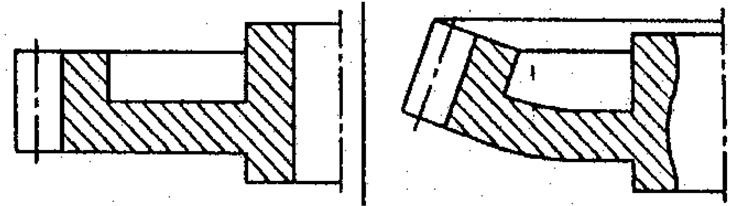
58 Precision Geometry Web Off-Center Web Centered m = 1.0 mm; z = 28; = 20 ; b = 15 mm; Hostaform C Ticona Gears Webinar Gear_DesignPPT_AM_0212_016.pdf
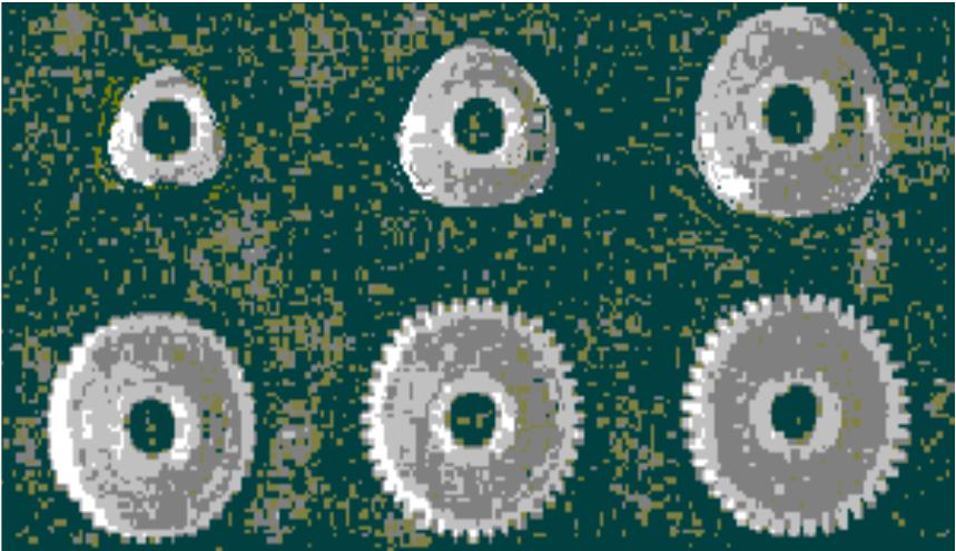
59 Precision Ribs 6 Ribs 12 Ribs No Ribs m = 1.0 mm; z = 28; = 20 ; b = 15 mm; Hostaform C Ticona Gears Webinar Gear_DesignPPT_AM_0212_016.pdf


60 Precision Gates Ticona Gears Webinar Gear_DesignPPT_AM_0212_016.pdf

61 Precision Gates Filling Roundness Ticona Gears Webinar Gear_DesignPPT_AM_0212_016.pdf

62 Precision Gates Filling Roundness Ticona Gears Webinar Gear_DesignPPT_AM_0212_016.pdf
63 Precision Mold Cooling Bad Better Ticona Gears Webinar Gear_DesignPPT_AM_0212_016.pdf
64 Precision Mold Cooling Best Ticona Gears Webinar Gear_DesignPPT_AM_0212_016.pdf
65 Prototyping Verification of part and material performance Verification of manufacturing capabilities with dimensional control Represent production as mush as possible Mold Molding conditions Mold material # cavities, runners, gates, etc. Cooling channels Molder Molding machine Barrel size residence time Injection rate Clamp tonnage Identical to Production Temperatures Mold Melt Cycle profile Injection speed Hold time & pressure Cooling time Screw RPM & back pressure Ticona Gears Webinar Gear_DesignPPT_AM_0212_016.pdf
66 Prototype Mold Development Precision Follow material supplier s molding recommendations Establish appropriate processing window Maximize material properties Resist correcting dimensions with extreme processing conditions Wide, stable processing window Minimal variational effects on properties and dimensions Maximize dimensional stability Consistent as-molded dimensions Precision vs. cycle time Minimize post-molding shrinkage Mold temperature must exceed operating temperature Pay now, or pay later! Design of experiments (DOE) Ticona Gears Webinar Gear_DesignPPT_AM_0212_016.pdf Stability Equals Precision

67 Prototype Mold Development Accuracy Then correct tooling for shrinkage Cut molds steel safe Undersized cavities Oversized cores Use inserts Iterate Measure thoroughly Make what you designed Then Correct for Accuracy Ticona Gears Webinar Gear_DesignPPT_AM_0212_016.pdf
68 Outline 1. Why plastics for gears 2. Gear types and arrangements for plastics 3. Design and engineering 4. Specifications 5. Prototype parts and mold development 6. Measurement and inspection 7. Testing and validation 8. Production molding Ticona Gears Webinar Gear_DesignPPT_AM_0212_016.pdf
69 Plastic Gear Development Cycle Design & Engineering Prints & Specifications Prototype Tool & Parts Measurement & Inspection Testing Production Ticona Gears Webinar Gear_DesignPPT_AM_0212_016.pdf
 General inspection Outside radius Root radius Tooth thickness Measurement over pins or balls Elemental Inspection for Development 70 2012 Ticona Gears Webinar Gear_DesignPPT_AM_0212_016.pdf")
70 Inspection and Geometry Verification During development Elemental inspection (CNC) Profile error (involute error) Lead error (helix angle error) Pitch error (spacing error) Runout (radial position error) General inspection Outside radius Root radius Tooth thickness Measurement over pins or balls Elemental Inspection for Development Ticona Gears Webinar Gear_DesignPPT_AM_0212_016.pdf
 Tooth-to-tooth error (TTE) Runout Composite Inspection for QC 71 2012 Ticona Gears Webinar Gear_DesignPPT_AM_0212_016.")
71 Inspection and Geometry Verification During production Composite inspection (Double-flank roll checker) Total composite error (TCE) Tooth-to-tooth error (TTE) Runout Composite Inspection for QC Ticona Gears Webinar Gear_DesignPPT_AM_0212_016.pdf
72 Outline 1. Why plastics for gears 2. Gear types and arrangements for plastics 3. Design and engineering 4. Specifications 5. Prototype parts and mold development 6. Measurement and inspection 7. Testing and validation 8. Production molding Ticona Gears Webinar Gear_DesignPPT_AM_0212_016.pdf

73 Testing and Validation Geometry verification! Realistic Properly represents end-use conditions Continuous testing when end-use is intermittent Overheating No thermal or dimensional recovery time Temperature control Effective Static loads Creep and creep rupture Impact loads Motor stall load Motor rotor inertia load Appropriate Test procedures often developed for metal gears Ticona Gears Webinar Gear_DesignPPT_AM_0212_016.pdf Keep It Real
74 Plastic Gear Development Cycle Design & Engineering Prints & Specifications Prototype Tool & Parts Measurement & Inspection Testing Production Ticona Gears Webinar Gear_DesignPPT_AM_0212_016.pdf
75 Outline 1. Why plastics for gears 2. Gear types and arrangements for plastics 3. Design and engineering 4. Specifications 5. Prototype parts and mold development 6. Measurement and inspection 7. Testing and validation 8. Production molding Ticona Gears Webinar Gear_DesignPPT_AM_0212_016.pdf

76 Production Utilize prototype knowledge Minimize deviations Mold Mold machine Molding conditions Wide, stable process Maximum material properties Consistent dimensions Correct tooling for accuracy Measure thoroughly Make what you designed and verified Run capability study Establish production QC methodology Produce! Ticona Gears Webinar Gear_DesignPPT_AM_0212_016.pdf
77 Thank You Questions? Ticona Gears Webinar Gear_DesignPPT_AM_0212_016.pdf


78 David Sheridan Sr. Design Engineer Product Information Ticona Gears Webinar Gear_DesignPPT_AM_0212_016.pdf
79 NOTICE TO USERS: Information is current as of February 2012 and is subject to change without notice. The information contained in this publication should not be construed as a promise or guarantee of specific properties of our products. Any determination of the suitability of a particular material and part design for any use contemplated by the user is the sole responsibility of the user. We strongly recommend that users seek and adhere to the manufacturer s current instructions for handling each material they use. Any existing intellectual property rights must be observed Ticona. Except as otherwise noted, trademarks are owned by Ticona or its affiliates Ticona Gears Webinar Gear_DesignPPT_AM_0212_016.pdf
How to Achieve a Successful Molded Gear Transmission
 How to Achieve a Successful Molded Gear Transmission Rod Kleiss Figure 1 A molding insert tool alongside the molded gear and the gear cavitiy. Molded plastic gears have very little in common with machined
Part VII: Gear Systems: Analysis
 Part VII: Gear Systems: Analysis This section will review standard gear systems and will provide the basic tools to perform analysis on these systems. The areas covered in this section are: 1) Gears 101:
Ernie Reiter and Irving Laskin
 F I N E P I T C H, P L A S T I C FA C E G E A R S : Design Ernie Reiter and Irving Laskin Ernie Reiter is a consultant specializing in the design of gears and geared products. He has authored modern software
GEAR CONTENTS POWER TRANSMISSION GEAR TYPES OF GEARS NOMENCLATURE APPLICATIONS OF GEARS VELOCITY RATIO GEAR TRAINS EXAMPLE PROBLEMS AND QUESTIONS
 GEAR CONTENTS POWER TRANSMISSION GEAR TYPES OF GEARS NOMENCLATURE APPLICATIONS OF GEARS VELOCITY RATIO GEAR TRAINS EXAMPLE PROBLEMS AND QUESTIONS GEAR.. Power transmission is the movement of energy from
Kaydon white paper. The importance of properly mounting thin section bearings. an SKF Group brand. by Rob Roos, Senior Product Engineer
 The importance of properly mounting thin section by Rob Roos, Senior Product Engineer an SKF Group brand Figure 1 Radial Load Reversing Thrust Overturning Moment Thin section ball have a much thinner cross-section
Gear Tooth Geometry - This is determined primarily by pitch, depth and pressure angle
 Gear Tooth Geometry - This is determined primarily by pitch, depth and pressure angle Addendum: The radial distance between the top land and the pitch circle. Addendum Circle: The circle defining the outer
Using and Specifying Plastic Gears Zan Smith, Ticona Staff Engineer and Maribeth Fletcher, Celcon Product Manager - General Industries
 Using and Specifying Plastic Gears Zan Smith, Ticona Staff Engineer and Maribeth Fletcher, Celcon Product Manager - General Industries For mechanical engineers, plastic gears are a powerful means of cutting
Introduction. Kinematics and Dynamics of Machines. Involute profile. 7. Gears
 Introduction The kinematic function of gears is to transfer rotational motion from one shaft to another Kinematics and Dynamics of Machines 7. Gears Since these shafts may be parallel, perpendicular, or
Copyright Notice. Small Motor, Gearmotor and Control Handbook Copyright Bodine Electric Company. All rights reserved.
 Copyright Notice Small Motor, Gearmotor and Control Handbook Copyright 1993-2003 Bodine Electric Company. All rights reserved. Unauthorized duplication, distribution, or modification of this publication,
Sheet 1 Variable loading
 Sheet 1 Variable loading 1. Estimate S e for the following materials: a. AISI 1020 CD steel. b. AISI 1080 HR steel. c. 2024 T3 aluminum. d. AISI 4340 steel heat-treated to a tensile strength of 1700 MPa.
Mounting Overlap Shield. Face Clamps. Gap. Seat Depth. Lead In Chamfer. Loose Fit.
 Mounting Introduction: Reali-Slim thin section ball bearings have a crosssection thickness that is much thinner than standard bearings of the same diameter, and are therefore more sensitive to shaft and
Chapter 8 Kinematics of Gears
 Chapter 8 Kinematics of Gears Gears! Gears are most often used in transmissions to convert an electric motor s high speed and low torque to a shaft s requirements for low speed high torque: Speed is easy
CH#13 Gears-General. Drive and Driven Gears 3/13/2018
 CH#13 Gears-General A toothed wheel that engages another toothed mechanism in order to change the speed or direction of transmitted motion The gear set transmits rotary motion and force. Gears are used
Lecture (7) on. Gear Measurement. By Dr. Emad M. Saad. Industrial Engineering Dept. Faculty of Engineering. Fayoum University.
 on. Gear Measurement. By Dr. Emad M. Saad. Industrial Engineering Dept. Faculty of Engineering. Fayoum University.") 1 Lecture (7) on Gear Measurement Fayoum University By Dr. Emad M. Saad Industrial Engineering Dept. Faculty of Engineering Fayoum University Faculty of Engineering Industrial Engineering Dept. 2015-2016
1 Lecture (7) on Gear Measurement Fayoum University By Dr. Emad M. Saad Industrial Engineering Dept. Faculty of Engineering Fayoum University Faculty of Engineering Industrial Engineering Dept. 2015-2016
 DEPARTMENT OF MECHANICAL ENGINEERING Subject code: ME6601 Subject Name: DESIGN OF TRANSMISSION SYSTEMS UNIT-I DESIGN OF TRANSMISSION SYSTEMS FOR FLEXIBLE ELEMENTS 1. What is the effect of centre distance
Program Internal Gear Set Profile Shift Coefficients With Zero Backlash Introduction
 Program 60-107 Internal Gear Set Profile Shift Coefficients With Zero Backlash Introduction The purpose of this model is to provide data for a gear set when the tooth thickness and/or the center distance
Chapter 3. Transmission Components
 Chapter 3. Transmission Components The difference between machine design and structure design An important design problem in a mechanical system is how to transmit and convert power to achieve required
Chapter seven. Gears. Laith Batarseh
 Chapter seven Gears Laith Batarseh Gears are very important in power transmission between a drive rotor and driven rotor What are the functions of gears? - Transmit motion and torque (power) between shafts
CHAPTER 5 PREVENTION OF TOOTH DAMAGE IN HELICAL GEAR BY PROFILE MODIFICATION
 90 CHAPTER 5 PREVENTION OF TOOTH DAMAGE IN HELICAL GEAR BY PROFILE MODIFICATION 5.1 INTRODUCTION In any gear drive the absolute and the relative transmission error variations normally increases with an
KINGS COLLEGE OF ENGINEERING DEPARTMENT OF MECHANICAL ENGINEERING
 KINGS COLLEGE OF ENGINEERING DEPARTMENT OF MECHANICAL ENGINEERING QUESTION BANK Sub Code/Name: ME 1352 DESIGN OF TRANSMISSION SYSTEMS Year/Sem: III / VI UNIT-I (Design of transmission systems for flexible
DUDLEY'S" HANDBOOK OF PRACTICAL GEAR DESIGN AND MANUFACTURE. Stephen P. Radzevich
 Second Edition DUDLEY'S" HANDBOOK OF PRACTICAL GEAR DESIGN AND MANUFACTURE Stephen P. Radzevich LßP) CRC Press VV J Taylors Francis Group Boca Raton London New York CRC Press is an imprint of the Taylor
1/2/2015 2:04 PM. Chapter 13. Gears General. Dr. Mohammad Suliman Abuhaiba, PE
 Chapter 13 Gears General 1 2 Chapter Outline 1. Types of Gears 2. Nomenclature 3. Conjugate Action 4. Involute Properties 5. Fundamentals 6. Contact Ratio 7. Interference 8. The Forming of Gear Teeth 9.
Quindos the Ultimate Software package for Gears, Gear Tools and other Special Applications
 Quindos the Ultimate Software package for Gears, Gear Tools and other Special Applications Quindos gear packages Gearings Cylindrical Gear Unknown Gear Involute & Lead Master Straight Bevel Gear Spiral
What are the functions of gears? What is gear?
 8//0 hapter seven Laith atarseh are very important in power transmission between a drive rotor and driven rotor What are the functions of gears? - Transmit motion and torque (power) between shafts - Maintain
12/6/2013 9:09 PM. Chapter 13. Gears General. Dr. Mohammad Suliman Abuhaiba, PE
 Chapter 13 Gears General 1 2 Chapter Outline 1. Types of Gears 2. Nomenclature 3. Conjugate Action 4. Involute Properties 5. Fundamentals 6. Contact Ratio 7. Interference 8. The Forming of Gear Teeth 9.
Shifting gears: simplify your design with slewing ring bearings
 White Paper Shifting gears: simplify your design with slewing ring bearings Scott Hansen, VP, Manufacturing Planning, Kaydon Bearings, an SKF Group company A slewing ring bearing has rolling elements designed
Selecting Inching Drives for Mill and Kiln Applications
 Article Reprint Selecting Inching Drives for Mill and Kiln Applications Glen Cahala Frank C Uherek, Principal Engineer - Gear Engineering Software Development Abstract The ing drive, also known as a barring
ME6401 KINEMATICS OF MACHINERY UNIT- I (Basics of Mechanism)
") ME6401 KINEMATICS OF MACHINERY UNIT- I (Basics of Mechanism) 1) Define resistant body. 2) Define Link or Element 3) Differentiate Machine and Structure 4) Define Kinematic Pair. 5) Define Kinematic Chain.
ME6401 KINEMATICS OF MACHINERY UNIT- I (Basics of Mechanism) 1) Define resistant body. 2) Define Link or Element 3) Differentiate Machine and Structure 4) Define Kinematic Pair. 5) Define Kinematic Chain.
KISSsoft 03/2017 Tutorial 15
 KISSsoft 03/2017 Tutorial 15 Bevel gears KISSsoft AG Rosengartenstrasse 4 8608 Bubikon Switzerland Tel: +41 55 254 20 50 Fax: +41 55 254 20 51 info@kisssoft.ag www.kisssoft.ag Contents 1 Starting KISSsoft...
Six keys to achieving better precision in linear motion control applications
 profile Drive & Control Six keys to achieving better precision in linear motion control applications Achieving precise linear motion Consider these factors when specifying linear motion systems: Equipped
Chapter 7. Shafts and Shaft Components
 Chapter 7 Shafts and Shaft Components 2 Chapter Outline Introduction Shaft Materials Shaft Layout Shaft Design for Stress Deflection Considerations Critical Speeds for Shafts Miscellaneous Shaft Components
CLASSIFICATION OF ROLLING-ELEMENT BEARINGS
 CLASSIFICATION OF ROLLING-ELEMENT BEARINGS Ball bearings can operate at higher speed in comparison to roller bearings because they have lower friction. In particular, the balls have less viscous resistance
Gear Measurement. Lecture (7) Mechanical Measurements
 Mechanical Measurements") 18 3. Gear profile checking 2. Involute measuring machine In this method the gear is held on a mandrel and circular disc of same diameter as the base circle of gear for the measurement is fixed on the
18 3. Gear profile checking 2. Involute measuring machine In this method the gear is held on a mandrel and circular disc of same diameter as the base circle of gear for the measurement is fixed on the
The Geometry of Involute Gears
 The Geometry of Involute Gears J.R. Colbourne The Geometry of Involute Gears With 217 Illustrations Springer-Verlag New York Berlin Heidelberg London Paris Tokyo J.R. Colbourne Department of Mechanical
In-house development Own manufacturing Sole distributor in Germany Working with distributors worldwide
 In-house development Own manufacturing Sole distributor in Germany Working with distributors worldwide External Clamping devices Overview 3073 Mini-Range For very low torque transmission Very small profile
Gearheads H-51. Gearheads for AC Motors H-51
 Technical Reference H-51 for AC Since AC motor gearheads are used continuously, primarily for transmitting power, they are designed with priority on ensuring high permissible torque, long life, noise reduction
KISSsoft 03/2013 Tutorial 15
 KISSsoft 03/2013 Tutorial 15 Bevel gears KISSsoft AG Rosengartenstrasse 4 8608 Bubikon Switzerland Tel: +41 55 254 20 50 Fax: +41 55 254 20 51 info@kisssoft.ag www.kisssoft.ag Contents 1 Starting KISSsoft...
Therefore, it is the general practice to test the tooth contact and backlash with a tester. Figure 19-5 shows the ideal contact for a worm gear mesh.
 19. Surface Contact Of Worm And Worm Gear There is no specific Japanese standard concerning worm gearing, except for some specifications regarding surface contact in JIS B 1741. Therefore, it is the general
Catalog Q Conversion For those wishing to ease themselves into working with metric gears
 1.3.4 Conversion For those wishing to ease themselves into working with metric gears by looking at them in terms of familiar inch gearing relationships and mathematics, Table 1-5 is offered as a means
Innovative PPS Blow-Molded Air Duct for Turbocharged Diesel Engine
 Innovative PPS Blow-Molded Air Duct for Turbocharged Diesel Engine High Performance Polymers for Automotive Powertrain Applications Duane Emerson Ticona Engineering Polymers SPE ACCE Conference September
EFFICIENZA E ANALISI TERMICA. Ing. Ivan Saltini Italy Country Manager
 EFFICIENZA E ANALISI TERMICA Ing. Ivan Saltini Italy Country Manager How to get most realistic efficiency calculation for gearboxes? Topics Motivation / general calculation Industrial bevel-helical gearbox
Design of Helical Gear and Analysis on Gear Tooth
 Design of Helical Gear and Analysis on Gear Tooth Indrale Ratnadeep Ramesh Rao M.Tech Student ABSTRACT Gears are mainly used to transmit the power in mechanical power transmission systems. These gears
Program Center Distance Change
 Introduction Program 60-146--Center Distance Change When the coefficient of thermal expansion of the material used for gears is different from the coefficient for the mountg or housg material, it is necessary
Customer Application Examples
 Customer Application Examples The New, Powerful Gearwheel Module 1 SIMPACK Usermeeting 2006 Baden-Baden 21. 22. March 2006 The New, Powerful Gearwheel Module L. Mauer INTEC GmbH Wessling Customer Application
SECTION 8 BEVEL GEARING
 SECTION 8 BEVEL GEARING For intersecting shafts, bevel gears offer a good means of transmitting motion and power. Most transmissions occur at right angles, Figure 8-1, but the shaft angle can be any value.
KISSsoft Tutorial 012: Sizing of a fine pitch Planetary Gear set. 1 Task. 2 Starting KISSsoft
 KISSsoft Tutorial: Sizing of a fine pitch Planetary Gear set KISSsoft Tutorial 012: Sizing of a fine pitch Planetary Gear set For Release: 10/2008 kisssoft-tut-012-e-sizing-of-planetary-gear-set.doc Last
Engineering Information
 Engineering nformation Gear Nomenclature ADDENDUM (a) is the height by which a tooth projects beyond the pitch circle or pitch line. BASE DAMETER (D b ) is the diameter of the base cylinder from which
DESIGN OF MACHINE ELEMENTS UNIVERSITY QUESTION BANK WITH ANSWERS. Unit 1 STEADY STRESSES AND VARIABLE STRESSES IN MACHINE MEMBERS
 DESIGN OF MACHINE ELEMENTS UNIVERSITY QUESTION BANK WITH ANSWERS Unit 1 STEADY STRESSES AND VARIABLE STRESSES IN MACHINE MEMBERS 1.Define factor of safety. Factor of safety (FOS) is defined as the ratio
Technical Publications Catalog. October 2016
 Technical Publications Catalog October 2016 Table of Contents How to Purchase Documents... 1 Index of AGMA Standards and Information Sheets by Number... 1 Index of AGMA Standards and Information Sheets
ScienceDirect A NEW EXPERIMENTAL APPROACH TO TEST OPEN GEARS FOR WINCH DRUMS
 Available online at www.sciencedirect.com ScienceDirect Procedia Engineering 133 (2015 ) 192 201 6th Fatigue Design conference, Fatigue Design 2015 A NEW EXPERIMENTAL APPROACH TO TEST OPEN GEARS FOR WINCH
AN OPTIMAL PROFILE AND LEAD MODIFICATION IN CYLINDRICAL GEAR TOOTH BY REDUCING THE LOAD DISTRIBUTION FACTOR
 AN OPTIMAL PROFILE AND LEAD MODIFICATION IN CYLINDRICAL GEAR TOOTH BY REDUCING THE LOAD DISTRIBUTION FACTOR Balasubramanian Narayanan Department of Production Engineering, Sathyabama University, Chennai,
ANALYSIS OF GEAR QUALITY CRITERIA AND PERFORMANCE OF CURVED FACE WIDTH SPUR GEARS
 8 FASCICLE VIII, 8 (XIV), ISSN 11-459 Paper presented at Bucharest, Romania ANALYSIS OF GEAR QUALITY CRITERIA AND PERFORMANCE OF CURVED FACE WIDTH SPUR GEARS Laurentia ANDREI 1), Gabriel ANDREI 1) T, Douglas
Marswell Engineering Ltd.
 Marswell Engineering Ltd. Specialized in small module plastic gearing and gearbox Automated injection molding and molds for any small, precision component. Table of content page table of content i Background
Spur Gears. Helical Gears. Bevel Gears. Worm Gears
 Spur s General: Spur gears are the most commonly used gear type. They are characterized by teeth which are perpendicular to the face of the gear. Spur gears are by far the most commonly available, and
11. GEAR TRANSMISSIONS
 11. GEAR TRANSMISSIONS 11.1. GENERAL CONSIDERATIONS Gears are one of the most important elements used in machinery. There are few mechanical devices that do not have the need to transmit power and motion
ANALYSIS OF SURFACE CONTACT STRESS FOR A SPUR GEAR OF MATERIAL STEEL 15NI2CR1MO28
 ANALYSIS OF SURFACE CONTACT STRESS FOR A SPUR GEAR OF MATERIAL STEEL 15NI2CR1MO28 D. S. Balaji, S. Prabhakaran and J. Harish Kumar Department of Mechanical Engineering, Chennai, India E-Mail: balajimailer@gmail.com
Bibliography. [1] Buckingham, Earle: "Analytical Mechanics of Gears", McGraw-Hill, New York, 1949, and republished by Dover, New York, 1963.
![Bibliography. [1] Buckingham, Earle: Analytical Mechanics of Gears, McGraw-Hill, New York, 1949, and republished by Dover, New York, 1963.](/thumbs/87/96820687.jpg "Bibliography. [1] Buckingham, Earle: Analytical Mechanics of Gears, McGraw-Hill, New York, 1949, and republished by Dover, New York, 1963.") Bibliography The first five references listed are books on gearing. Some of them deal not only with the geometry, but also with many other aspects of gearing. However, the books are included in this bibliography
Bibliography The first five references listed are books on gearing. Some of them deal not only with the geometry, but also with many other aspects of gearing. However, the books are included in this bibliography
Direction of Helix (R) No. of Teeth (20) Module (1) Others (Ground Gear) Type (Helical Gear) Material (SCM440)
 No. of Teeth (20) Module (1) Others (Ground Gear) Type (Helical Gear) Material (SCM440)") KH round Series Newly added m1 ~ 3 Page 168 SH Steel m2, 3 Page 178 CP acks acks Catalog Number of KHK Stock The Catalog Number for KHK stock gears is based on the simple formula listed below. Please order
KH round Series Newly added m1 ~ 3 Page 168 SH Steel m2, 3 Page 178 CP acks acks Catalog Number of KHK Stock The Catalog Number for KHK stock gears is based on the simple formula listed below. Please order
(POWER TRANSMISSION Methods)
") UNIT-5 (POWER TRANSMISSION Methods) It is a method by which you can transfer cyclic motion from one place to another or one pulley to another pulley. The ways by which we can transfer cyclic motion are:-
UNIT-5 (POWER TRANSMISSION Methods) It is a method by which you can transfer cyclic motion from one place to another or one pulley to another pulley. The ways by which we can transfer cyclic motion are:-
Technical Publications Catalog. October 2015
 Technical Publications Catalog October 2015 Table of Contents How to Purchase Documents... 1 Index of AGMA Standards and Information Sheets by Number... 1 Index of AGMA Standards and Information Sheets
Graphical representation of a gear
 Homework 4 Gears Gears are designed to transmit rotary motion. Often they are arranged in a gear train (meshed together). Gear trains provide a change in speed, torque (turning force) and direction (clockwise
Methodology for Designing a Gearbox and its Analysis
 Methodology for Designing a Gearbox and its Analysis Neeraj Patel, Tarun Gupta B.Tech, Department of Mechanical Engineering, Maulana Azad National Institute of Technology, Bhopal, India. Abstract Robust
Is Low Friction Efficient?
 Is Low Friction Efficient? Assessment of Bearing Concepts During the Design Phase Dipl.-Wirtsch.-Ing. Mark Dudziak; Schaeffler Trading (Shanghai) Co. Ltd., Shanghai, China Dipl.-Ing. (TH) Andreas Krome,
10 Thrust ball bearings
 10 Thrust ball bearings Designs and variants.............. 1010 Single direction thrust ball bearings... 1010 Double direction thrust ball bearings.. 1010 Cages............................ 1010 Bearings
Figure 1.1 "Bevel and hypoid gears" "Modules" Figure / August 2011 Release 03/2011
 KISSsoft Tutorial 015: Bevel Gears KISSsoft AG - +41 55 254 20 50 Uetzikon 4 - +41 55 254 20 51 8634 Hombrechtikon - info@kisssoft. AG Switzerland - www. KISSsoft. AG KISSsoft Tutorial: Bevel Gears 1 Starting
ME6601 DESIGN OF TRANSMISSION SYSTEMS
 SYED AMMAL ENGINEERING COLLEGE (Approved by the AICTE, New Delhi, Govt. of Tamilnadu and Affiliated to Anna University, Chennai) Established in 1998 - An ISO 9001:2008 Certified Institution Dr. E.M.Abdullah
Polymers Outperform Metals In Precision Gearing
 WHITE PAPER Power of knowledge engineering Polymers Outperform Metals In Precision Gearing Some of the most innovative gears today are not made from metal or injection-molded plastics but from machined
Gear Drives. A third gear added to the system will rotate in the same direction as the drive gear Equal diameters = Equal number of teeth = Same speed
 Gear Drive Systems Gear Drives Gear Drive: Synchronous mechanical drive that uses gears to transfer power Gear: A toothed wheel that meshes with other toothed wheels to transfer rotational power Pinion
Technical Publications Catalog. April 2014
 Technical Publications Catalog April 2014 Table of Contents American Gear Manufacturers Association... iii How to Purchase Documents... 1 Index of AGMA Standards and Information Sheets by Number... 1 Index
GEARING. Theory of. Stephen. Kinetics, Geometry, and Synthesis. P. Radzevich. /Ov CRC Press yc*** J Taylor& Francis Croup Boca Raton
 Theory of GEARING Kinetics, Geometry, and Synthesis Stephen P. Radzevich /Ov CRC Press yc*** J Taylor& Francis Croup Boca Raton London New York CRC Press is an imprint of the Taylor & Francis Group, an
Transmission Error in Screw Compressor Rotors
 Purdue University Purdue e-pubs International Compressor Engineering Conference School of Mechanical Engineering 2008 Transmission Error in Screw Compressor Rotors Jack Sauls Trane Follow this and additional
Tribology Aspects in Angular Transmission Systems
 Tribology Aspects in Angular Transmission Systems Part II Straight Bevel Gears Dr. Hermann Stadtfeld (This is the second of an eight-part series on the tribology aspects of angular gear drives. Each article
GatesFacts Technical Information Library Gates Compass Power Transmission CD-ROM version 1.2 The Gates Rubber Company Denver, Colorado USA
 SELECTING SYNCHRONOUS BELTS FOR PRECISE POSITIONING A W Wallin Power Transmission Design February, 1989 Synchronous belts are well known for precise positioning. However, some precision applications require
Thermal Analysis of Helical and Spiral Gear Train
 International Journal for Ignited Minds (IJIMIINDS) Thermal Analysis of Helical and Spiral Gear Train Dr. D V Ghewade a, S S Nagarale b & A N Pandav c a Principal, Department of Mechanical, GENESIS, Top-Kolhapur,
15. Bearing Handling Storage Fitting A-97
 15. Bearing Handling Bearings are precision parts, and in order to preserve their accuracy and reliability, care must be exercised in their handling. In particular, bearing cleanliness must be maintained,
The Available Solution CYCLO DRIVE. Gearmotors & Speed Reducers. Series
 The Available Solution CYCLO DRIVE Gearmotors & Speed Reducers 6000 Series WHAT DO YOU THINK OF THIS? THESE ARE THE ADVANTAGES OF THE NEWEST CYCLO, 6000 SERIES: More frame sizes, gear ratios and motor
ANALYSIS OF SPUR GEAR GEOMETRY AND STRENGTH WITH KISSSOFT SOFTWARE
 ANALYSIS OF SPUR GEAR GEOMETRY AND STRENGTH WITH KISSSOFT SOFTWARE Ashwini Gaikwad 1, Rajaram Shinde 2 1,2 Automobile Engineering Department, Rajarambapu Institute of Technology, Sakharale, Dist. Sangli,
Bearing Handling. 15. Bearing Handling Bearing storage Installation
 15. Bearing Handling Bearings are precision parts and, in order to preserve their accuracy and reliability, care must be exercised in their handling. In particular, bearing cleanliness must be maintained,
1.7 Backlash. Summary of the backlash is play or clearance between one pair of gear. Fig. 17 Backlash
 1.7 Backlash Summary of the backlash is play or clearance between one pair of gear. Fig. 17 Backlash Great care is taken to produce the gear with zero deviation. However we are unable to completely eliminate
2. a) What is pantograph? What are its uses? b) Prove that the peaucellier mechanism generates a straight-line motion. (5M+10M)
 What is pantograph? What are its uses? b) Prove that the peaucellier mechanism generates a straight-line motion. (5M+10M)") Code No: R22032 R10 SET - 1 1. a) Define the following terms? i) Link ii) Kinematic pair iii) Degrees of freedom b) What are the inversions of double slider crank chain? Describe any two with neat sketches.
Code No: R22032 R10 SET - 1 1. a) Define the following terms? i) Link ii) Kinematic pair iii) Degrees of freedom b) What are the inversions of double slider crank chain? Describe any two with neat sketches.
PIPINGSOLUTIONS, INC.
 Piping Stress Analysis Where do I start? The following information will take you step-by-step through the logic of the data collection effort that should occur prior to beginning to model a piping system
Internal Gears. No. of teeth (60) Module (1) Others (Ring Gear) Type (Internal Gear) Material (S45C)
 Module (1) Others (Ring Gear) Type (Internal Gear) Material (S45C)") ph: (410)8-10 (0)68-180 fx: (410)8-142 (0)872-929 rfq form: http://mdmetric.com/rfq.htm Internal Internal Miter CP Racks & Pinions Racks Helical Spur SI Steel Internal SIR Steel Ring m0. ~ Page 184 m2
ph: (410)8-10 (0)68-180 fx: (410)8-142 (0)872-929 rfq form: http://mdmetric.com/rfq.htm Internal Internal Miter CP Racks & Pinions Racks Helical Spur SI Steel Internal SIR Steel Ring m0. ~ Page 184 m2
Bevel Gears. Fig.(1) Bevel gears
 Bevel gears") Bevel Gears Bevel gears are cut on conical blanks to be used to transmit motion between intersecting shafts. The simplest bevel gear type is the straighttooth bevel gear or straight bevel gear as can be
Bevel Gears Bevel gears are cut on conical blanks to be used to transmit motion between intersecting shafts. The simplest bevel gear type is the straighttooth bevel gear or straight bevel gear as can be
INCREASE IN FATIGUE LIFE OF SPUR GEAR BY INTRODUCING CIRCULAR STRESS RELIEVING FEATURE
 INTERNATIONAL JOURNAL OF MECHANICAL ENGINEERING AND International Journal of Mechanical Engineering and Technology (IJMET), ISSN 0976 6340(Print), ISSN 0976 6359(Online), Volume TECHNOLOGY 6, Issue 5,
Metrology Prof. Dr Kanakuppi Sadashivappa Bapuji Institute of Engineering and Technology Davangere. Lecture 25 Introduction of Gears
 Metrology Prof. Dr Kanakuppi Sadashivappa Bapuji Institute of Engineering and Technology Davangere Lecture 25 Introduction of Gears I welcome you for the series of lecture on gear measurement and at module
NODIA AND COMPANY. Model Test Paper - I GATE Machine Design. Copyright By Publishers
 No part of this publication may be reproduced or distributed in any form or any means, electronic, mechanical, photocopying, or otherwise without the prior permission of the author. Model Test Paper -
Chapter 7: Thermal Study of Transmission Gearbox
 Chapter 7: Thermal Study of Transmission Gearbox 7.1 Introduction The main objective of this chapter is to investigate the performance of automobile transmission gearbox under the influence of load, rotational
UNIT -I. Ans: They are specified by the no. of strands & the no. of wires in each strand.
 VETRI VINAYAHA COLLEGE OF ENGINEERING AND TECHNOLOGY, THOTTIAM, NAMAKKAL-621215. DEPARTMENT OF MECHANICAL ENGINEERING SIXTH SEMESTER / III YEAR ME6601 DESIGN OF TRANSMISSION SYSTEM (Regulation-2013) UNIT
TECHNICAL INFORMATION
 General Nomenclature Spherical Roller Bearings The spherical roller bearing is a combination radial and thrust bearing designed for taking misalignment under load When loads are heavy, alignment of housings
MANUFACTURING OF GEAR BOXES
 Profile No.: 29 NIC Code: 29301 MANUFACTURING OF GEAR BOXES 1. INTRODUCTION: Gears play a prominent role in mechanical power transmission. A gear or cogwheel is a rotating machine part having cut teeth,
Ball Rail Systems RE / The Drive & Control Company
 Ball Rail Systems RE 82 202/2002-12 The Drive & Control Company Rexroth Linear Motion Technology Ball Rail Systems Roller Rail Systems Standard Ball Rail Systems Super Ball Rail Systems Ball Rail Systems
A General Discussion of Gear Configurations
 A General Discussion of Gear Configurations 1. A. Single Helical a. Thrust Bearings b. Thrust collars c. Elimination of Thrust Bearings in Single Helical Units B. Double Helical 2. How Pitch Line Velocity
Mechanism Feasibility Design Task
 Mechanism Feasibility Design Task Dr. James Gopsill 1 Contents 1. Last Week 2. Types of Gear 3. Gear Definitions 4. Gear Forces 5. Multi-Stage Gearbox Example 6. Gearbox Design Report Section 7. This Weeks
Development of High Power Column-Type Electric Power Steering System
 TECHNICAL REPORT Development of High Power Column-Type Electric Power Steering System Y. NAGAHASHI A. KAWAKUBO T. TSUJIMOTO K. KAGEI J. HASEGAWA S. KAKUTANI Recently, demands have increased for column-type
CHAPTER 3 page 35 PRINCIPLES OF GEAR-TOOTH GENERATION. .1 Angular Velocity Ratio
 CHAPTER 1 page 1..., ATURE, NOTATION AND CONVENTIONS TYPES OF GEAR 1.1 Spur 1.2 Helical 1.3 Double-Helical 1.4 Crossed Helical 1.5 Conical Involute 1.6 Bevel 1.7 Spiral Bevel 1.8 Hypoid 1.9 Worm NOMENCLATURE
Planetary Roller Type Traction Drive Unit for Printing Machine
 TECHNICAL REPORT Planetary Roller Type Traction Drive Unit for Printing Machine A. KAWANO This paper describes the issues including the rotation unevenness, transmission torque and service life which should
Endurance+ Efficiency. A guide to plastic gearing
 Endurance+ Efficiency LNP Specialty Compounds A guide to plastic gearing SABIC Founded in 1976, SABIC is today the first public, global multinational enterprise headquartered in the Middle East. Our products
Structural Stress Analysis of Reduction Helical Gear box Casing
 International OPEN ACCESS Journal Of Modern Engineering Research (IJMER) Structural Stress Analysis of Reduction Helical Gear box Casing Sudhir Mane *, Vijay Patil ** * Department Of Mechanical Engineering,
Introduction to Gear Design
 Introduction to Gear Design Course No: M03-016 Credit: 3 PDH Robert P. Tata, P.E. Continuing Education and Development, Inc. 9 Greyridge Farm Court Stony Point, NY 10980 P: (877) 322-5800 F: (877) 322-4774
Why bigger isn t always better: the case for thin section bearings
 White Paper Why bigger isn t always better: the case for thin section bearings Richard Burgess, Les Miller and David VanLangevelde, Kaydon Bearings Typical applications Thin section bearings have proven