A General Discussion of Gear Configurations
|
|
|
- Maximilian Perry
- 6 years ago
- Views:
Transcription
1 A General Discussion of Gear Configurations 1. A. Single Helical a. Thrust Bearings b. Thrust collars c. Elimination of Thrust Bearings in Single Helical Units B. Double Helical 2. How Pitch Line Velocity affects the Pitch Line Velocity of the et 3. An Overview on Gear tooth Lead Corrections A. Temperature Effects 4. Understanding Thermal Ratings of Gearboxes A. Introduction B. On High Speed Units 5. Epicyclic Page: 1 of 14

2 The earliest gear drives utilized a spur gear tooth design. Although modification to the addendum, improves the smooth transfer of load from tooth to tooth with the introduction of a helix angle the transfer of load from tooth to tooth occurs at a slower rate. At the same time load sharing (more than one tooth in contact at any moment which shares the load) is increased due to the increase in the number of teeth in contact at any one time. With the tooth form optimized, this increases the contact or bearing area of the gear rotor consequently increasing surface load carrying capability. However a helix angle design introduces an axial component of force. There are a number of arrangements, which can be used to accommodate the axial force: 1. A. Single Helical a. Thrust Bearings The most traditional method for a single helical design is to utilize a tilting pad thrust bearings or if powers are low enough, an integrally constructed tapered land thrust bearing. The gear thrust is then absorbed by the thrust bearings incorporated within the gearbox. The use of the tapered land type is based on limits of either rotor of.5 N/mm sq. or approximately 4000 HP and/or 4000 RPM. b. Thrust Collars One very successful method is to incorporate a thrust collar on the pinion. Page: 2 of 14


3 This solution eliminates internal thrust. The tangential velocity between the collar and bearing surface is relative and so the resultant sliding velocity is small. A continuous oil film provides a hydrodynamic boundary, which eliminates metal to metal contact thereby providing an infinite life bearing. The disadvantage to this design is that the rotor needed to accommodate the thrust collar or collars increases the span support. Another problem with very high operating speeds for large power units involves keeping the collars on the shafts as these collars are shrunk on after machining. An example of an extreme gear successfully operating with this type design is a MAAG model type GBX-47 rated for HP and a speed increaser ratio 4950/9178 RPM. This gear has been in continuous service since Cost is another factor here however as thrust collars add cost to the gear and may result in a somewhat higher selling price. c. Elimination of Thrust Bearings in Single Helical Units An alternate arrangement is to locate the gear train off of a thrust bearing located in the driver or the driven equipment. It is important these thrust bearings be arranged in such a way so they do not oppose each other without consideration to axial flexibility in thermal growth or shaft run out. B Double Helical Another method is to split the helices into a left and right hand helix. This method eliminates internal thrust without thrust bearings while still maintaining a helical design for load sharing and smooth transfer of load from tooth to tooth. Without the need for Page: 3 of 14
4 thrust bearings double helical gears tend to be higher in efficiency and require less lube oil than single helical gears. However, this style gear is subject to a mismatch of the helices between the pinion and the gear. In the case of a single helix, the pinion can be adjusted to properly mesh with the gear whereas in the case of two helices a compromise must be made between left and right hand helices. Mismatch is not necessarily symmetrical but can be accumulative which further complicates mesh alignment. In double helical gears there is a certain error of the apex formed by the helices commonly referred to as apex wander resulting in an axial runout over one revolution of the rotor. This causes a shuttling of the pinion axially with respect to the gear during operation. This is evident as an axial vibration. It is particularly evident during a no load full speed mechanical running test. Under these, no load conditions the pinion is most subject to the internal errors of the gearset. Without any load to dampen or stabilize the pinion, inherent manufacturing errors take over and produce a vibration. In earlier times, double helical gears were constructed of softer through hardened gears, the pinion usually somewhat harder than the gear. This results in the pinion working the gear during operation by wearing it in. This process wears down the uneven loaded surface across the gear face width resulting from the mismatch until even load sharing across the gear face width is achieved. Oftentimes, at first, because the loading can be quite uneven, highly loaded localized areas of the toothing begin to show some initial pitting. Due to the higher sliding velocities of high-speed gears, this pitting could become quite severe. However, as the pinion and gear wear in, this condition slowly heals itself and the gearset develops a high degree of polish. But early day manufactured double helical turbo gears ran at lower speeds than what is demanded of today s highly loaded designs and so this condition was not serious. Also, because of slower speed conditions, the shuttling of the pinion due to apex runout was not a serious concern and this too worked itself out under load as the gearset wore in. With the increase of speeds in today s turbo market, the resulting PLV (pitch line velocity) has increased due to larger powers and higher speeds. The pinion moves too quickly for it to compensate for toothing errors and therefore does not have sufficient time to shuttle back and forth. As PLV levels exceed fpm, it is almost impossible for any movement to occur at all. The initial pitting may be severe enough that the quality of the tooth surface becomes questionable resulting in a condition where pitting is now in a destructive realm incapable of repairing itself. Thus the pitting continues until gear failure. Page: 4 of 14

5 2. How Gear Geometry affects the Pitch Line Velocity of a et It was evident very early in the history of the development of gear tooth geometry that as higher speeds were demanded from gears, a tooth form that provided quiet rolling contact was essential if the gears were to operate reliably. Hence the need to meet the following goals: Lower the sliding action in the gear mesh thereby allowing greater capability for the gearset to carry load. If the pinion/gear tooth surfaces could roll through engagement the surface wear will be reduced. Quieter running gears where lower noise is a needed quality. This was demanded of gear design in the earlier history of electric passenger railcar systems where quiet running gears were greatly desirable. Both of these factors fostered the development of the involute tooth form in gear design. This resulted in the optimum tooth form. Today the involute gear tooth form is the accepted design for of all high speed gear manufacturers in the world. The earliest drives utilized a straight spur gear tooth configuration with an involute tooth form. Modifying the tooth form assist the load entry and load distribution beyond a single tooth engagement while maintaining the involute profile. With the use of a helix angle the effective engagement beyond a single tooth is achieved by overlapping one tooth mesh with another. This added further load sharing of the gear teeth and the number of engaged toothing is referred to as the contact ratio. cos i 1 R b r i The combination for both is referred to as the total contact ratio. This results in an overlap ratio beyond a single tooth. Page: 5 of 14
6 The total contact ratio is the sum of the transverse contact ratio + the overlap ratio: The PLV (Ft/min) is calculated by: Є γ = Є α + Є β *n v = PLV (ft/min) a = gearset center to center distance, inches n1 = pinion rpm u = gear ratio From this relationship it can be seen that if the CD can be reduced the PLV will also be reduced. Thus if a gearset can be manufactured with higher load carrying capability, the elements are therefore reduced in size. This is achieved by gear hardening. The power rating capacity of a carburized gearset is considerably higher thereby reducing the size of the rotor geometry and lowering the PLV. This can be referenced by the allowable stress numbers listed in ANSI/AGMA D04 Sec Both single and double helical gearing benefits from the utilization of case carburized gearing with reduced rotor size and PLV for the same transmitted power. Great care must be given to gear accuracy to mitigate the aforementioned toothing errors. The purpose of reducing the PLV is to reduce the relative sliding action that occurs in the gear mesh. Although theoretically the involute form follows a line of contact nevertheless as the gear enters into contact and exits from contact with its mating part there exists some relative sliding velocity along the involute profile on the path of contact. The sliding velocity is detrimental to the gearset since it results in a power loss that translates into heat. This heat then increases the temperature of the gearset elements which expands the rotors and distorts the tooth form. The greater the distortion, the poorer the actual form the gear tooth in service becomes which further exacerbates the condition making for a poorly operating gearset. The combination of further distortion & relative tooth sliding could locally overload limited sections of the mating surfaces. This highly localized condition could fail the lube film thickness bringing the surface teeth into direct contact. The results may be surface distress (scuffing, micropitting, macropitting), thereby shortening gear life. For high pitch line velocities (greater than 100 m/s (19700 f/m) reliability of gears is challenged by higher face width thermal gradients. Gear tooth distortion, commonly referred to as barreling is a Page: 6 of 14
7 process combination of tooth & rotor deformation observed in service. During gear unit operation there is a high velocity axial flow of lube, oil and air across the helix(s) of the mesh. Through mesh engagement, oil and air are mixed and compressed resulting in an asymmetrical (uneven) tooth flank temperature gradient creating a linear distortion of the tooth lead across the face. 3 An Overview on Gear Tooth Lead Corrections When a pinion having uniform meshing at no load, is torqued at one end, it bends and twists according to a known algebraic combined deflection, the load distribution is proportional to the tooth deflection. For applications that require large gearboxes high pitch line velocities will increase scuffing risk due to higher sliding velocities and greater tooth quenching losses due to the increased velocity of oil/air combination traveling axially along the tooth face. This will require deeper lead and profile modifications which increase sensitivity to proper tooth contact. Gear teeth distortion, commonly referred to as barreling is a process combination of tooth & rotor deformation as described above. During gear unit operation the high velocity axial flow of lube, oil and air across the helix(s) of the mesh are mixed and compressed resulting in the asymmetrical (uneven) tooth flank temperature gradient. Lead and profile corrections to account for these deviations must be applied to the gear toothing thereby assuring uniform load distribution. Single helical gears are subject to greater thermal deformation due to lower helix angles and longer travel on the tooth face. Double helical gears benefit from the higher helix angle and shorter face travel thereby reducing the amount of thermal deformation. However the corrections for double helical gears are more complex. If less than optimum correction is discovered in during gear unit operation single helical gears are easily adjusted to align the mesh loads whereas double helical gears can only approximate the adjusted value. A. Temperature effects Usually the pinion operates at a higher temperature than the wheel. The pinion will expand and hence the pitch will change variably along the tooth face. The change in axial pitch is most important as this wears the teeth at one end of the helix Page: 7 of 14

8 In single helical gears the combination of deflection of deflection and distortion is a single accumulated deviation from the unloaded tooth. Single Helical Gear Toothing Deflections of the Lead In double helical gears the deflection is the same but the thermal distortion is split between the helices. The combined deviation is therefore more complex. However the thermal distortion is of lesser magnitude. With double helical gears the position of the helices relative to each other is important. If the apex is trailing into the mesh, the teeth bear hard on the inner ends and with apex leading the teeth bear hard on the outer ends. Apex trailing is advantageous as apex leading teeth tend to compound the effect of heat distortion into the torque distortion Page: 8 of 14

9 Double Helical Gear Toothing Deflections of the Lead 4 Understanding the Thermal Rating of Gearboxes A. Introduction This is a complex issue and not one with easy solutions. In the gearbox or power transmission industry, oftentimes we refer to the thermal efficiency of a gearbox, whether it is an increaser or reducer as the "thermal rating" of the gear unit. This means an assigned value measured in BTU's/min (joules/min) is converted to HP (kw) (power dissipated through the gear unit structure). If the gear unit utilizes a circulating lube oil system designed to both lubricate and cool the gear unit, the residual amount of heat not eliminated by the lube oil system but rather transferred out into the atmosphere or adjacent equipment becomes the measure of the thermal rating. Gear units vary in size and weight depending on the material of housing construction; for example fabricated steel, cast iron or aluminum. Each has a different heat coefficient. Each will be Page: 9 of 14


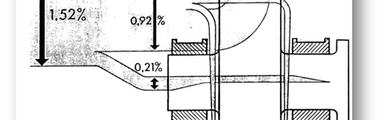
10 constructed according to strength. Carburized and ground gears have much higher load carrying capability than gears that are through hardened. This will vary the gear set size. Thus the total physical size of a gear unit can vary greatly depending on the technology used for design and construction of the gear set for the same power and speeds. And so the thermal rating will vary considerably as well. regardless of size in a parallel shaft single mesh configuration will have a mechanical efficiency of approximately 98%. So a rough rule of thumb would be a 2% loss per mesh. Therefore regardless of size the heat to be dissipated is the same. And bigger gears will dissipate heat better than smaller ones. If a gearbox has no circulating system for its lube oil but is depending on the rotors dipping and splashing oil for lubrication than the heat must be dissipated entirely through the housing walls. Sometimes fins are designed onto the housing for increasing the surface area to the atmosphere and thereby increasing the thermal rating. Further capacity to dissipate heat is sometimes accomplished with the addition of a fan or blower. B. On High speed gears The physical sizes of the gearset rotors are determined by the torque transmitted through the gearset. Torque is really the defining measure of size not power. A low speed machine of relatively modest horsepower can be physically larger than a high speed machine of lesser horsepower. However the inefficiency of the gear unit remains a percentage of the transmitted power. So high speed gears with high horsepower's produce a great amount of heat in a relatively small gear unit. In high speed units therefore the thermal rating becomes a small amount of the unit s ability to dissipate heat. Also windage losses from the rotors operating with high peripheral speeds will increase the losses and hence increase the amount of produced heat. The unit becomes entirely dependent on the lubrication circulating system for cooling. Much has been done in testing gears for a measurement of their efficiencies and thermal ratings. This includes gears from fractional HP up to 94,000 HP (70 MW). Here is an approximate breakdown of how the energy is dissipated in high speed gears: Bearings 42% Churning & Windage (air & oil) 85% Toothing 58% Friction 15% Page: 10 of 14

11 Page: 11 of 14


12 Typical illustration of gear efficiency: In this example: Gearbox is 29,000 HP - speeds: 4670 rpm/9022 rpm These efficiency curves are primarily theoretical. If some of the actual operating conditions of torque and speed are points along these curves, then the conditions diverge considerably from the nominal operating conditions for which the gear has been laid out. This means that various points which diverge must be recalculated, taking into account the gear tooth modifications for the nominal condition, for tooth load capacity. The above curves were calculated not considering the effect of the modifications, therefore it brings into question their practical use. Basically one should consider, for instance, that 100% load at 50% speed is only a theoretical point. If this is an actual point, then it should be known at the time the gear is designed to assure the operating conditions are optimized for actual service duty. Page: 12 of 14
13 Efficiency calculation methods: For the use of an analytical method see ANSI/AGMA 6011-I03 Annex F. An alternate method can be found in the latest revision of AGMA 6123-B06. For a simple means of calculating the gearbox oil flow requirement based on a given efficiency the following can be used; Or. ΔT = T 1 T 2 Where: T 1 = gearbox oil inlet temperature T 2 = gearbox oil outlet temperature 6. Epicyclic Powers and speeds are ever increasing requirements of gear drives increasing the physical size of the gear elements which in turn has resulted in higher pitch line velocities, higher mesh sliding velocities and wider face widths. This in turn places greater emphasis on accurate lead and profile corrections in order to compensate for the operating thermal deformation needed to assure good load distribution and reduced scuffing risk. But the thermal effects generate higher operating temperatures demanding closer attention to the quality of the lubricant employed, size and quality of the lubricating system and the frequency of maintenance schedules. Further metallurgical considerations which affect the behavior of the material in its operational environment is extremely Page: 13 of 14


14 important such as the heat treatment procedures and, relative amount of retained austenite in carburized elements. The use of epicyclic gears has been avoided by API due to the complexity of service and repair. However there are alternative solutions available which make these concerns more tolerable. Best of all epicyclic gearing directly provides alternative layouts that address the consequences listed above when compared to single mesh power paths in parallel shaft gear units. The advantage is a significant reduction in the pitch line velocity for a comparable parallel shaft unit with a single mesh power path thereby reducing the negative impact created by thermal affects. There are commercial advantages as well: 1. Envelope size (smaller than parallel shaft for same power) therefore less installed space required. 2. Coaxial Shafts (in line system) resulting in more compact installation 3. Lower weight 4. Lower cost for the entire train layout Epicyclic units is an alternative to applications where special considerations can take advantage of the epicyclic layout. The mesh rating of the gears in epicyclic units can apply to the same rating calculations for parallel shaft gears. Page: 14 of 14
API 613, FIFTH EDITION, SPECIAL PURPOSE GEAR UNITS FOR PETROLEUM, CHEMICAL AND GAS INDUSTRY SERVICES OVERVIEW PRESENTATION
 API 613, FIFTH EDITION, SPECIAL PURPOSE GEAR UNITS FOR PETROLEUM, CHEMICAL AND GAS INDUSTRY SERVICES OVERVIEW PRESENTATION by Robert W. (Wes) Conner Machinery Engineer Fluor Daniel Sugarland, Texas and
Copyright Notice. Small Motor, Gearmotor and Control Handbook Copyright Bodine Electric Company. All rights reserved.
 Copyright Notice Small Motor, Gearmotor and Control Handbook Copyright 1993-2003 Bodine Electric Company. All rights reserved. Unauthorized duplication, distribution, or modification of this publication,
High Speed Gears - New Developments
 High Speed Gears - New Developments by T. Oeeg Contents: 1. Introduction 2. Back to Back Test Bed 3. Radial Tilting Pad Bearings 3.1 Design 3.2 Test Results 3.3 Deformation Analysis 4. Axial Tilting Pad
UNIT -I. Ans: They are specified by the no. of strands & the no. of wires in each strand.
 VETRI VINAYAHA COLLEGE OF ENGINEERING AND TECHNOLOGY, THOTTIAM, NAMAKKAL-621215. DEPARTMENT OF MECHANICAL ENGINEERING SIXTH SEMESTER / III YEAR ME6601 DESIGN OF TRANSMISSION SYSTEM (Regulation-2013) UNIT
CHAPTER 5 PREVENTION OF TOOTH DAMAGE IN HELICAL GEAR BY PROFILE MODIFICATION
 90 CHAPTER 5 PREVENTION OF TOOTH DAMAGE IN HELICAL GEAR BY PROFILE MODIFICATION 5.1 INTRODUCTION In any gear drive the absolute and the relative transmission error variations normally increases with an
CH#13 Gears-General. Drive and Driven Gears 3/13/2018
 CH#13 Gears-General A toothed wheel that engages another toothed mechanism in order to change the speed or direction of transmitted motion The gear set transmits rotary motion and force. Gears are used
Introduction to Gear Design
 Introduction to Gear Design Course No: M03-016 Credit: 3 PDH Robert P. Tata, P.E. Continuing Education and Development, Inc. 9 Greyridge Farm Court Stony Point, NY 10980 P: (877) 322-5800 F: (877) 322-4774
ME6601 DESIGN OF TRANSMISSION SYSTEMS
 SYED AMMAL ENGINEERING COLLEGE (Approved by the AICTE, New Delhi, Govt. of Tamilnadu and Affiliated to Anna University, Chennai) Established in 1998 - An ISO 9001:2008 Certified Institution Dr. E.M.Abdullah
Gear Tooth Geometry - This is determined primarily by pitch, depth and pressure angle
 Gear Tooth Geometry - This is determined primarily by pitch, depth and pressure angle Addendum: The radial distance between the top land and the pitch circle. Addendum Circle: The circle defining the outer
Therefore, it is the general practice to test the tooth contact and backlash with a tester. Figure 19-5 shows the ideal contact for a worm gear mesh.
 19. Surface Contact Of Worm And Worm Gear There is no specific Japanese standard concerning worm gearing, except for some specifications regarding surface contact in JIS B 1741. Therefore, it is the general
Sheet 1 Variable loading
 Sheet 1 Variable loading 1. Estimate S e for the following materials: a. AISI 1020 CD steel. b. AISI 1080 HR steel. c. 2024 T3 aluminum. d. AISI 4340 steel heat-treated to a tensile strength of 1700 MPa.
12/6/2013 9:09 PM. Chapter 13. Gears General. Dr. Mohammad Suliman Abuhaiba, PE
 Chapter 13 Gears General 1 2 Chapter Outline 1. Types of Gears 2. Nomenclature 3. Conjugate Action 4. Involute Properties 5. Fundamentals 6. Contact Ratio 7. Interference 8. The Forming of Gear Teeth 9.
1/2/2015 2:04 PM. Chapter 13. Gears General. Dr. Mohammad Suliman Abuhaiba, PE
 Chapter 13 Gears General 1 2 Chapter Outline 1. Types of Gears 2. Nomenclature 3. Conjugate Action 4. Involute Properties 5. Fundamentals 6. Contact Ratio 7. Interference 8. The Forming of Gear Teeth 9.
Analysis of Eclipse Drive Train for Wind Turbine Transmission System
 ISSN 2395-1621 Analysis of Eclipse Drive Train for Wind Turbine Transmission System #1 P.A. Katre, #2 S.G. Ganiger 1 pankaj12345katre@gmail.com 2 somu.ganiger@gmail.com #1 Department of Mechanical Engineering,
HYBRID LINEAR ACTUATORS BASICS
 HYBRID LINEAR ACTUATORS BASICS TECHNICAL OVERVIEW Converting the rotary motion of a stepping motor into linear motion can be accomplished by several mechanical means, including rack and pinion, belts and
LESSON Transmission of Power Introduction
 LESSON 3 3.0 Transmission of Power 3.0.1 Introduction Earlier in our previous course units in Agricultural and Biosystems Engineering, we introduced ourselves to the concept of support and process systems
SECTION 8 BEVEL GEARING
 SECTION 8 BEVEL GEARING For intersecting shafts, bevel gears offer a good means of transmitting motion and power. Most transmissions occur at right angles, Figure 8-1, but the shaft angle can be any value.
Integral Gear Unit MULTICOM
 Innovative Power Transmission RENK-MAAG Integral Gear Unit MULTICOM The heart of multi-tiered compressor systems! RENK-MAAG MULTICOM gearbox GMX (for integrally geared compressors) Integral Gear Unit MULTICOM
Gearheads H-51. Gearheads for AC Motors H-51
 Technical Reference H-51 for AC Since AC motor gearheads are used continuously, primarily for transmitting power, they are designed with priority on ensuring high permissible torque, long life, noise reduction
Determination and improvement of bevel gear efficiency by means of loaded TCA
 Determination and improvement of bevel gear efficiency by means of loaded TCA Dr. J. Thomas, Dr. C. Wirth, ZG GmbH, Germany Abstract Bevel and hypoid gears are widely used in automotive and industrial
Introduction. Kinematics and Dynamics of Machines. Involute profile. 7. Gears
 Introduction The kinematic function of gears is to transfer rotational motion from one shaft to another Kinematics and Dynamics of Machines 7. Gears Since these shafts may be parallel, perpendicular, or
Vacuum gearbox HET Gear
 Innovative Power Transmission RENK-MAAG Vacuum gearbox Worth a mint in just a short time! RENK-MAAG (High Efficiency Turbo Gear) Vacuum gearbox world s most efficient turbo gear The RENK-MAAG (High Efficiency
KISSsoft 03/2017 Tutorial 15
 KISSsoft 03/2017 Tutorial 15 Bevel gears KISSsoft AG Rosengartenstrasse 4 8608 Bubikon Switzerland Tel: +41 55 254 20 50 Fax: +41 55 254 20 51 info@kisssoft.ag www.kisssoft.ag Contents 1 Starting KISSsoft...
CLASSIFICATION OF ROLLING-ELEMENT BEARINGS
 CLASSIFICATION OF ROLLING-ELEMENT BEARINGS Ball bearings can operate at higher speed in comparison to roller bearings because they have lower friction. In particular, the balls have less viscous resistance
Spur gearing, Helical gearing [mm/iso] Pinion Gear ii Project information? i Calculation without errors.
![Spur gearing, Helical gearing [mm/iso] Pinion Gear ii Project information? i Calculation without errors.](/thumbs/80/81955134.jpg "Spur gearing, Helical gearing [mm/iso] Pinion Gear ii Project information? i Calculation without errors.") S Spur gearing, Helical gearing [mm/iso] i Calculation without errors. Pinion Gear ii Project information? Input section 1. Options of basic input parameters 1.1 Transferred power Pw [kw] 9.67 9.63 1.2
S Spur gearing, Helical gearing [mm/iso] i Calculation without errors. Pinion Gear ii Project information? Input section 1. Options of basic input parameters 1.1 Transferred power Pw [kw] 9.67 9.63 1.2
1.7 Backlash. Summary of the backlash is play or clearance between one pair of gear. Fig. 17 Backlash
 1.7 Backlash Summary of the backlash is play or clearance between one pair of gear. Fig. 17 Backlash Great care is taken to produce the gear with zero deviation. However we are unable to completely eliminate
Chapter 8 Kinematics of Gears
 Chapter 8 Kinematics of Gears Gears! Gears are most often used in transmissions to convert an electric motor s high speed and low torque to a shaft s requirements for low speed high torque: Speed is easy
Chapter 3. Transmission Components
 Chapter 3. Transmission Components The difference between machine design and structure design An important design problem in a mechanical system is how to transmit and convert power to achieve required
Methodology for Designing a Gearbox and its Analysis
 Methodology for Designing a Gearbox and its Analysis Neeraj Patel, Tarun Gupta B.Tech, Department of Mechanical Engineering, Maulana Azad National Institute of Technology, Bhopal, India. Abstract Robust
KINGS COLLEGE OF ENGINEERING DEPARTMENT OF MECHANICAL ENGINEERING
 KINGS COLLEGE OF ENGINEERING DEPARTMENT OF MECHANICAL ENGINEERING QUESTION BANK Sub Code/Name: ME 1352 DESIGN OF TRANSMISSION SYSTEMS Year/Sem: III / VI UNIT-I (Design of transmission systems for flexible
Mechanism Feasibility Design Task
 Mechanism Feasibility Design Task Dr. James Gopsill 1 Contents 1. Last Week 2. Types of Gear 3. Gear Definitions 4. Gear Forces 5. Multi-Stage Gearbox Example 6. Gearbox Design Report Section 7. This Weeks
1.8 Rack shift of the gear
 1.8 Rack shift of the gear Undercut When Number of teeth is belo minimum as shon in Fig. 3, part of dedendum is no longer an Involute curve but ill look like a shape scooped out by cutter tool. Refer to
The Available Solution CYCLO DRIVE. Gearmotors & Speed Reducers. Series
 The Available Solution CYCLO DRIVE Gearmotors & Speed Reducers 6000 Series WHAT DO YOU THINK OF THIS? THESE ARE THE ADVANTAGES OF THE NEWEST CYCLO, 6000 SERIES: More frame sizes, gear ratios and motor
Part VII: Gear Systems: Analysis
 Part VII: Gear Systems: Analysis This section will review standard gear systems and will provide the basic tools to perform analysis on these systems. The areas covered in this section are: 1) Gears 101:
Shifting gears: simplify your design with slewing ring bearings
 White Paper Shifting gears: simplify your design with slewing ring bearings Scott Hansen, VP, Manufacturing Planning, Kaydon Bearings, an SKF Group company A slewing ring bearing has rolling elements designed
Effect of Geometry Factor I & J Factor Multipliers in the performance of Helical Gears
 Effect of Geometry Factor I & J Factor Multipliers in the performance of Helical Gears 1 Amit D. Modi, 2 Manan B. Raval, 1 Lecturer, 2 Lecturer, 1 Department of Mechanical Engineering, 2 Department of
Technical Publications Catalog. October 2015
 Technical Publications Catalog October 2015 Table of Contents How to Purchase Documents... 1 Index of AGMA Standards and Information Sheets by Number... 1 Index of AGMA Standards and Information Sheets
Gear Drives. A third gear added to the system will rotate in the same direction as the drive gear Equal diameters = Equal number of teeth = Same speed
 Gear Drive Systems Gear Drives Gear Drive: Synchronous mechanical drive that uses gears to transfer power Gear: A toothed wheel that meshes with other toothed wheels to transfer rotational power Pinion
Technical Publications Catalog. April 2014
 Technical Publications Catalog April 2014 Table of Contents American Gear Manufacturers Association... iii How to Purchase Documents... 1 Index of AGMA Standards and Information Sheets by Number... 1 Index
Tooth thickness Dedendum. Addendum. Centre distance Nominal
 FORMULAS SPUR GEARS TO FIND:- PCD ØD MODULE No. of TEETH CP ADDENDUM DEDENDUM MODULE No. of TEETH x MOD (mm) (No. of TEETH + ) x MOD (mm) 5.4 MODULE CP π (mm) PCD MODULE (mm) MODULE x π (mm) MODULE (mm)
o f Tip Relief on Transmission
 E v a l u a t i o n o f M e t h o d s f o r C a l c u l a t i n g E f f e c t s o f Tip Relief on Transmission E r r o r, N o i s e a n d S t r e s s i n L o a d e d S p u r G e a r s Dr. David Palmer
TECHNICAL PAPER. New Opportunities with Molded Gears. by: R.E. Kleiss, A.L. Kapelevich and N.J. Kleiss Jr., Kleiss Gears, Inc.
 01FTM9 New Opportunities with Molded Gears by: R.E. Kleiss, A.L. Kapelevich and N.J. Kleiss Jr., Kleiss Gears, Inc. American Gear Manufacturers Association TECHNICAL PAPER New Opportunities with Molded
TE 73 TWO ROLLER MACHINE
 TE 73 TWO ROLLER MACHINE Background The TE 73 family of machines dates back to original Plint and Partners Ltd designs from the 1960s. These machines are all to the overhung roller design in which test
Model Dual Function Planetary Gear Reducer
 Model 3210 Dual Function Planetary Gear Reducer I. OVERVIEW The Model 3210 Planetary Gear Reducer is an extremely robust, dual function power transmission device that combines a conventional (in line)
Fig. 1 Two stage helical gearbox
 Lecture 17 DESIGN OF GEARBOX Contents 1. Commercial gearboxes 2. Gearbox design. COMMERICAL GEARBOX DESIGN Fig. 1 Two stage helical gearbox Fig. 2. A single stage bevel gearbox Fig. 4 Worm gearbox HELICAL
KISSsoft 03/2013 Tutorial 15
 KISSsoft 03/2013 Tutorial 15 Bevel gears KISSsoft AG Rosengartenstrasse 4 8608 Bubikon Switzerland Tel: +41 55 254 20 50 Fax: +41 55 254 20 51 info@kisssoft.ag www.kisssoft.ag Contents 1 Starting KISSsoft...
(POWER TRANSMISSION Methods)
") UNIT-5 (POWER TRANSMISSION Methods) It is a method by which you can transfer cyclic motion from one place to another or one pulley to another pulley. The ways by which we can transfer cyclic motion are:-
UNIT-5 (POWER TRANSMISSION Methods) It is a method by which you can transfer cyclic motion from one place to another or one pulley to another pulley. The ways by which we can transfer cyclic motion are:-
bearings (metric series)
") Taper roller bearings (metric series) 32302 B J2 / Q CL7C Nomenclature 1 2 3 4 1. Contact angle: 3. Features: B Larger contact angle than standard Q Improved friction torque characteristics and raceway
Taper roller bearings (metric series) 32302 B J2 / Q CL7C Nomenclature 1 2 3 4 1. Contact angle: 3. Features: B Larger contact angle than standard Q Improved friction torque characteristics and raceway
Why bigger isn t always better: the case for thin section bearings
 White Paper Why bigger isn t always better: the case for thin section bearings Richard Burgess, Les Miller and David VanLangevelde, Kaydon Bearings Typical applications Thin section bearings have proven
MAAG TM LGD lateral gear drive for horizontal mills
 MAAG TM LGD lateral gear drive for horizontal mills 2 Our Quality Policy FLSmidth MAAG Gear is committed to creating long lasting relationships that establish us as a trustworthy, reliable and professional
Simple Gears and Transmission
 Simple Gears and Transmission Simple Gears and Transmission page: of 4 How can transmissions be designed so that they provide the force, speed and direction required and how efficient will the design be?
ScienceDirect A NEW EXPERIMENTAL APPROACH TO TEST OPEN GEARS FOR WINCH DRUMS
 Available online at www.sciencedirect.com ScienceDirect Procedia Engineering 133 (2015 ) 192 201 6th Fatigue Design conference, Fatigue Design 2015 A NEW EXPERIMENTAL APPROACH TO TEST OPEN GEARS FOR WINCH
Chapter 1 Gear Design
 Chapter 1 Gear Design GTU Paper Analysis Sr. No. Questions Nov 16 May 17 Nov 17 May 18 Theory 1. Explain the following terms used in helical gears: (a) Helix angle; (b) Normal pitch; (c) Axial pitch; (d)
11. GEAR TRANSMISSIONS
 11. GEAR TRANSMISSIONS 11.1. GENERAL CONSIDERATIONS Gears are one of the most important elements used in machinery. There are few mechanical devices that do not have the need to transmit power and motion
The development of a differential for the improvement of traction control
 The development of a differential for the improvement of traction control S E CHOCHOLEK, BSME Gleason Corporation, Rochester, New York, United States of America SYNOPSIS: An introduction to the function
Part C: Electronics Cooling Methods in Industry
 Part C: Electronics Cooling Methods in Industry Indicative Contents Heat Sinks Heat Pipes Heat Pipes in Electronics Cooling (1) Heat Pipes in Electronics Cooling (2) Thermoelectric Cooling Immersion Cooling
TRANSLATION (OR LINEAR)
") 5) Load Bearing Mechanisms Load bearing mechanisms are the structural backbone of any linear / rotary motion system, and are a critical consideration. This section will introduce most of the more common
5) Load Bearing Mechanisms Load bearing mechanisms are the structural backbone of any linear / rotary motion system, and are a critical consideration. This section will introduce most of the more common
Engineering Information
 Engineering nformation Gear Nomenclature ADDENDUM (a) is the height by which a tooth projects beyond the pitch circle or pitch line. BASE DAMETER (D b ) is the diameter of the base cylinder from which
LAPPING OR GRINDING? WHICH TECHNOLOGY IS THE RIGHT CHOICE IN THE AGE OF INDUSTRY 4.0?
 LAPPING OR GRINDING? WHICH TECHNOLOGY IS THE RIGHT CHOICE IN THE AGE OF INDUSTRY 4.0? Bevel gear transmissions for the automotive industry are subject to extremely stringent requirements. They must be
Simple Gears and Transmission
 Simple Gears and Transmission Contents How can transmissions be designed so that they provide the force, speed and direction required and how efficient will the design be? Initial Problem Statement 2 Narrative
GEARBOXES. Gearboxes. Gearboxes. Gearbox is a mechanical device utilized to increase the output torque or change
 GEARBOXES Gearboxes Gearboxes Gearbox is a mechanical device utilized to increase the output torque or change the speed of a motor. The motor's shaft is attached to one end of the gearbox and through the
Technical Publications Catalog. October 2016
 Technical Publications Catalog October 2016 Table of Contents How to Purchase Documents... 1 Index of AGMA Standards and Information Sheets by Number... 1 Index of AGMA Standards and Information Sheets
Ball Rail Systems RE / The Drive & Control Company
 Ball Rail Systems RE 82 202/2002-12 The Drive & Control Company Rexroth Linear Motion Technology Ball Rail Systems Roller Rail Systems Standard Ball Rail Systems Super Ball Rail Systems Ball Rail Systems
Bevel Gears. Fig.(1) Bevel gears
 Bevel gears") Bevel Gears Bevel gears are cut on conical blanks to be used to transmit motion between intersecting shafts. The simplest bevel gear type is the straighttooth bevel gear or straight bevel gear as can be
Bevel Gears Bevel gears are cut on conical blanks to be used to transmit motion between intersecting shafts. The simplest bevel gear type is the straighttooth bevel gear or straight bevel gear as can be
1104 Highway 27 W Alexandria, MN
 1104 Highway 27 W Alexandria, MN 56308 800-253-7940 www.itwheartland.com APPLICATION GUIDE A certified leader in precision engineered machines, parts, gears, and electro-mechanical products for over 30
AGMA Catalog of Technical Publications
 Topic AGMA Catalog of Technical Publications 2000-2007 TABLE OF CONTENTS American Gear Manufacturers Association... ii How to Purchase ocuments... iii Index of AGMA Standards and Information Sheets by
SECTION 4 SPUR GEAR CALCULATIONS
 Function of α, or invα, is known as involute function. Involute function is very important in gear design. Involute function values can be obtained from appropriate tables. With the 3.1 Contact Ratio center
PRECISION BELLOWS COUPLINGS
 PRECISION BELLOWS COUPLINGS Bellows couplings are used where precise rotation, high speeds, and dynamic motion must be transmitted. They exhibit zero backlash and a high level of torsional stiffness, offering
FEM Analysis and Development of Eclipse Gearbox for Wind Turbine
 International Journal of Current Engineering and Technology E-ISSN 2277 4106, P-ISSN 2347 5161 2016 INPRESSCO, All Rights Reserved Available at http://inpressco.com/category/ijcet Research Article G.B.
Tribology Aspects in Angular Transmission Systems
 Tribology Aspects in Angular Transmission Systems Part II Straight Bevel Gears Dr. Hermann Stadtfeld (This is the second of an eight-part series on the tribology aspects of angular gear drives. Each article
Program Internal Gear Set Profile Shift Coefficients With Zero Backlash Introduction
 Program 60-107 Internal Gear Set Profile Shift Coefficients With Zero Backlash Introduction The purpose of this model is to provide data for a gear set when the tooth thickness and/or the center distance
Specification for High Speed Helical Gear Units
 ANSI/AGMA 6011- I03 (Revision of ANSI/AGMA 6011--H98) AMERICAN NATIONAL STANDARD Specification for High Speed Helical Gear Units ANSI/AGMA 6011-I03 American National Standard Specification for High Speed
Transmission Error in Screw Compressor Rotors
 Purdue University Purdue e-pubs International Compressor Engineering Conference School of Mechanical Engineering 2008 Transmission Error in Screw Compressor Rotors Jack Sauls Trane Follow this and additional
Design of Helical Gear and Analysis on Gear Tooth
 Design of Helical Gear and Analysis on Gear Tooth Indrale Ratnadeep Ramesh Rao M.Tech Student ABSTRACT Gears are mainly used to transmit the power in mechanical power transmission systems. These gears
Determination of the optimum flank line modifications for gear pairs and for planetary stages
 Determination of the optimum flank line modifications for gear pairs and for planetary stages Authors: Dr. Ing. Ulrich Kissling, KISSsoft AG Dipl. Ing. Hanspeter Dinner, EES-KISSsoft GmbH KISSsoft AG Rosengartenstrasse
 DEPARTMENT OF MECHANICAL ENGINEERING Subject code: ME6601 Subject Name: DESIGN OF TRANSMISSION SYSTEMS UNIT-I DESIGN OF TRANSMISSION SYSTEMS FOR FLEXIBLE ELEMENTS 1. What is the effect of centre distance
Enhanced gear efficiency calculation including contact analysis results and drive cycle consideration
 Enhanced gear efficiency calculation including contact analysis results and drive cycle consideration Dipl.-Ing. J. Langhart, KISSsoft AG, CH-Bubikon; M. Sc. T. Panero, KISSsoft AG, CH-Bubikon Abstract
Spiroid High Torque Skew Axis Gearing A TECHNICAL PRIMER F. EVERTZ, M. GANGIREDDY, B. MORK, T. PORTER & A. QUIST
 2016 Spiroid High Torque Skew Axis Gearing A TECHNICAL PRIMER F. EVERTZ, M. GANGIREDDY, B. MORK, T. PORTER & A. QUIST Table of Contents INTRODUCTION PAGE 02 SPIROID GEAR SET CHARACTERISTICS PAGE 03 BASIC
GEAR NOISE REDUCTION BY NEW APPROACHES IN GEAR FINISHING PROCESSES
 GEAR NOISE REDUCTION BY NEW APPROACHES IN GEAR FINISHING PROCESSES Nikam Akshay 1, Patil Shubham 2, Pathak Mayur 3, Pattewar Vitthal 4, Rawanpalle Mangesh 5 1,2,3,4,5 Department of Mechanical Engineering,
Seals Stretch Running Friction Friction Break-Out Friction. Build With The Best!
 squeeze, min. = 0.0035 with adverse tolerance build-up. If the O-ring is made in a compound that will shrink in the fluid, the minimum possible squeeze under adverse conditions then must be at least.076
How to Achieve a Successful Molded Gear Transmission
 How to Achieve a Successful Molded Gear Transmission Rod Kleiss Figure 1 A molding insert tool alongside the molded gear and the gear cavitiy. Molded plastic gears have very little in common with machined
EXPERIENCE WITA SPECIAL APPLIcATIrnS
 EXPERIENCE WITA SPECIAL APPLIcATIrnS by R. Schoch 1 Splitter Gears for Distribution 2 Large Gear Boxes with Thrust Collars 3 Parallel Shaft Gears with Extreme, Speed and Pitch Line Velocity 4 Epicyclic
Chapter seven. Gears. Laith Batarseh
 Chapter seven Gears Laith Batarseh Gears are very important in power transmission between a drive rotor and driven rotor What are the functions of gears? - Transmit motion and torque (power) between shafts
Topic 1. Basics of Oil Hydraulic Systems
 Topic 1. Basics of Oil Hydraulic Systems Fluid power Fluid power is the technology that deals with the generation, control and transmission of forces and movement of mechanical element or system with the
C. Brake pads Replaceable friction surfaces that are forced against the rotor by the caliper piston.
 BRAKES UNIT 1: INTRODUCTION TO BRAKE SYSTEMS LESSON 1: FUNDAMENTAL PRINCIPLES OF BRAKE SYSTEMS I. Terms and definitions A. Brake fading Loss of brakes, usually due to heat. B. Brake lining Material mounted
KISSsoft Tutorial 012: Sizing of a fine pitch Planetary Gear set. 1 Task. 2 Starting KISSsoft
 KISSsoft Tutorial: Sizing of a fine pitch Planetary Gear set KISSsoft Tutorial 012: Sizing of a fine pitch Planetary Gear set For Release: 10/2008 kisssoft-tut-012-e-sizing-of-planetary-gear-set.doc Last
Bearing preload. Preload considerations
 Bearing preload There may be some applications where the bearing arrangement needs to be preloaded i.e. requires a negative operating clearance. In applications such as machine tool spindles, automotive
GEAR GENERATION GEAR FORMING. Vipin K. Sharma
 GEAR GENERATION GEAR FORMING 1 GEAR MANUFACTURING Manufacturing of gears needs several processing operations in sequential stages depending upon the material and type of the gears and quality desired.
INVOLUTE TOOLING CORPORATION
 MANUFACTURERS OF DRIVES AND TRANSMISSIONS OFFICE: 13, JORBAGH, NEW DELHI - 110 003, INDIA, TEL: +91(011)24621453 FAX: +91(011) 24603609 WORKS: PLOT-65, SEC-27C, FARIDABAD - 121 003. INDIA, TEL: +91(0129)
AN OPTIMAL PROFILE AND LEAD MODIFICATION IN CYLINDRICAL GEAR TOOTH BY REDUCING THE LOAD DISTRIBUTION FACTOR
 AN OPTIMAL PROFILE AND LEAD MODIFICATION IN CYLINDRICAL GEAR TOOTH BY REDUCING THE LOAD DISTRIBUTION FACTOR Balasubramanian Narayanan Department of Production Engineering, Sathyabama University, Chennai,
Features of the LM Guide
 Features of the Functions Required for Linear Guide Surface Large permissible load Highly rigid in all directions High positioning repeatability Running accuracy can be obtained easily High accuracy can
Design & Development of Precision Plastic Gear Transmissions
 Design & Development of Precision Plastic Gear Transmissions David Sheridan Senior Design Engineer TICONA 1 2012 Ticona Gears Webinar Gear_DesignPPT_AM_0212_016.pdf Overview Methodical and rational procedure
Spur Gears. Helical Gears. Bevel Gears. Worm Gears
 Spur s General: Spur gears are the most commonly used gear type. They are characterized by teeth which are perpendicular to the face of the gear. Spur gears are by far the most commonly available, and
Influential Criteria on the Optimization of a Gearbox, with Application to an Automatic Transmission
 Influential Criteria on the Optimization of a Gearbox, with Application to an Automatic Transmission Peter Tenberge, Daniel Kupka and Thomas Panéro Introduction In the design of an automatic transmission
FZG Rig-Based Testing of Flank Load-Carrying Capacity Internal Gears
 FZG Rig-Based Testing of Flank Load-Carrying Capacity Internal Gears B.-R. Höhn, K. Stahl, J. Schudy, T. Tobie and B. Zornek (Printed with permission of the copyright holder, the American Gear Manufacturers
DESIGN OF DC MACHINE
 DESIGN OF DC MACHINE 1 OUTPUT EQUATION P a = power developed by armature in kw P = rating of machine in kw E = generated emf, volts; V = terminal voltage, volts p = number of poles; I a = armaure current,
Comparison Chart. extremely difficult. Finally, separated components can rarely be re-used.
 JAN 2014 Traditional Connections Why Go Keyless Keyed Bushing Systems Both QD and Taper-Lock bushing and weld-on hub systems are popular component mounting technologies. Yet both are ultimately keyed connections
MAIN SHAFT SUPPORT FOR WIND TURBINE WITH A FIXED AND FLOATING BEARING CONFIGURATION
 Technical Paper MAIN SHAFT SUPPORT FOR WIND TURBINE WITH A FIXED AND FLOATING BEARING CONFIGURATION Tapered Double Inner Row Bearing Vs. Spherical Roller Bearing On The Fixed Position Laurentiu Ionescu,
A pump is a machine used to move liquid through a piping system and to raise the pressure of the liquid.
 What is a pump A pump is a machine used to move liquid through a piping system and to raise the pressure of the liquid. Why increase a liquid s pressure? Static elevation a liquid s pressure must be increased
Aero-Engine Fan Gearbox Design
 The 16 th Israeli Symposium on Jet Engines and Gas Turbines November 9, 2017 Aero-Engine Fan Gearbox Design Presented by: Ilan Berlowitz BEDEK Aviation Group, Aircraft & Programs Division Israel Aerospace