Set your Mobile Phones to Silent Respect your colleagues no private conversations Be on time
|
|
|
- Delphia Lawson
- 5 years ago
- Views:
Transcription


1 Set your Mobile Phones to Silent Respect your colleagues no private conversations Be on time E. Francalanza 1


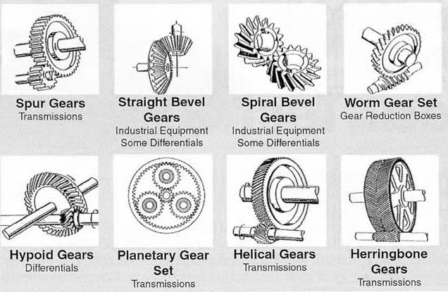
2 Thread Applications Thread Manufacturing Thread Design Thread Gaging Thread Measurement CMMs Gears Gear Applications Gear Manufacturing Gear Design Gear Measurement E. Francalanza 2

3 Coordinate Measuring Machines (CMMs) are extremely powerful metrological instruments: they enable us to locate point coordinates on three-dimensional structures. When we add a computer to the CMM, we create an instrument that c automatically perform complex analysis and that can learn measurement routines to compare how a piece conforms to its specifications. E. Francalanza 3
 and performing cumbersome mathematics, you can dimensionally evaluate complex workpieces with precision and speed- and you can store data for later")

4 Instead of performing timeconsuming measurements with traditional, single axis instruments (micrometres, height gages, etc.) and performing cumbersome mathematics, you can dimensionally evaluate complex workpieces with precision and speed- and you can store data for later analysis or comparisons. The greater the complexity of the piece, the greater the benefits from a CMM. Coordinate measuring machines play an important role in a large number of industries, including aerospace, automotive, electronics, food processing, health care, paper, pharmaceuticals, plastics, research and development and semiconductor. E. Francalanza 4


5 The ability to quickly and accurately capture and evaluate dimensional data distinguishes the CMM from other types of measurement processes. Sophisticated contact and noncontact sensors, combined with vast computer processing capabilities, make the CMM a practical, cost-effective solution. By reducing inspection time on the order of 80-90%, CMMs become a viable solution. CMMs are particularly suited for the following conditions: Short runs We may be producing hundreds or even thousands of a part, but the production run is not sufficient to justify the cost of production inspection tooling. Multiple features When we have a number of features, both dimensional and geometric, to control, CMM is the instrument that makes control easy and economical. Flexibility Because we can choose the application of the CMM system, we can also do short runs and measure multiple features. E. Francalanza 5
6 CMMs are particularly suited for the following conditions: High Unit Cost Because reworking or scrapping is costly, CMM systems significantly increases the production of acceptable parts. Production interruption Whenever you have to inspect and pass one part before you can start machining on the next part, a machining centre may actually be able to help a manufacturer save more money by reducing down time than would be saved by inspection. Cantilever Type In the cantilever-type CMM, a vertical probe moves in the z axis, carried by a cantilevered arm that moves in the y axis. This arm also moves laterally through the x axis. You have easy access to the work area, and the cantilever CMM provides a relatively large envelope without taking up too much floor space. E. Francalanza 6


7 Moving Bridge Type The most popular type of CMM, this machine has a moving bridge. It is similar to the cantilever type, because it has a support for the outer ends of the y-axis bean on the base. The bridge construction adds rigidity to the machine, but it also forces us to make sure that both ends of the y axis track at exactly the same rate. Column Type This CMMs construction is similar to the most popular type of jig borer and is often referred to as a universal measuring machine, instead of a CMM. The column type CMMs construction provides exceptional rigidity and accuracy, and these machines are usually reserved for gage rooms rather then inspection. E. Francalanza 7


8 Horizontal Arm Type Unlike the pervious machines, the basic horizontal arm-type CMM, also referred to as a layout machine, has a moving arm and the probe is carried along the y axis. This machine s main advantage is that it provides a large, unobstructed work area, which makes it perfect for very large workpieces like automotive dies. Gantry Type CMM In this type, the support of the workpiece is independent of the x and y axes, both of which are overhead, supported by four vertical columns rising from the floor. This setup allows you to walk along the workpiece with the probe, which is helpful for extremely large pieces. E. Francalanza 8


9 Sometimes a manufacturer will find it impractical or impossible to move a part of assembly to a stationary CMM. In those instances, a portable arm CMM can move to the part. Portable CMMs are an articulated measuring arm, with precision bearings and rotary transducers at eac of tis joints. Manual A manual mode CMM has a free floating probe that you, as the operator, move along the machine s three axes to establish contact with the part feature you are assessing. The differences between the contact positions are the measurements E. Francalanza 9
10 Manual Computer Assisted In the manual computer-assisted mode, we add electronic digital displays for these machines, making zero setting; changing the sign; converting inch and SI; and printing out data easy and practical. Even without further sophistication, these features save time, minimize calculations, and reduce errors. Motorized Computer Assisted A motorized CMM uses a joystick to drive the machine exes. The operator manipulates the joystick to bring the probe sensor into contact with the workpiece. E. Francalanza 10

11 Direct Computer Controlled (DCC) A direct computer controlled CMM is fully programmable. The CMM uses taught locations of CAD data to determine where the probe sensor contacts the workpiece, collecting measurement data. The fully automated CMM allows the operator to place the workpiece in a fixture or on the worktable, run a sored program, collect the data points, and generate an output reports. E. Francalanza 11
12 The probe is at the heart of the CMM operation. All CMMs consist of a probe and a way to move it along three axes relative to a workpiece. In a sense a CMM is three calipers placed in an orthogonal array. Probes fall into two general categories: Contact Non Contact Contact probes are the most commonly used on CMMs. Contact probes can include touch-trigger probes, and analogue scanning probes which maintain contact with the part as they can along the surface of the part as they measure. Noncontact probes include laser and video probes. E. Francalanza 12


13 Non Contact Probes Scanning Probes Laser Probes Non Contact Probes Video Probes Touch Trigger Probes The programming of the machine or the software of the system enables a CMM to reach its full potential for accuracy, precision, and speed. Contour programs allow the CMM to quickly define detailed, complex non-geometric shapes without straight edges such as gears, cams, and injection moulds. These programs also can be used to compare the measurement data with a CAD Model. E. Francalanza 13


14 CMM manufacturers claim repeatability to or in excess of 2.5µm and accuracy of 10µm, however these values decrease as the size of the CMM increases. Designers and manufacturers of CMMs take care that their machines, through their function, fulfil the fundamental principles of metrology, and features like system rigidity and the capability of the probe system make their success possible. E. Francalanza 14
15 CMMs reduce computational errors, but this reduction must be balanced with any errors that we might find in the programming. When you manually measure, you add systematic error because of the method you use, even though you may not even recognize the errors are there. E. Francalanza 15


16 E. Francalanza 16


17 Gearboxes and Differentials At the heart of each motorized vehicle lies an extremely complex system which makes use of different types of gears to transmit torque in varying ratios from the engine to the wheels. From Grandfather Clocks to Wristwatches With the move to the digital age, gears in clocks and watches are loosing their importance. Yet the most luxurious and exclusive watches all use gears as their principal mechanism. E. Francalanza 17


18 CD Drives, Printer and Scanners These items can be found on each desk in every office. They make use of gears to achieve linear or rotary motion from electrical motors. Mountain Bikes One of the most notorious gear manufacturers Shimano, produces gears for mountain bikes. E. Francalanza 18


19 Broaching is one of the most common methods to manufacture gears. Two types of broaches exist: Internal and External. Broaching uses a toothed tool to remove material. It is used for machining of gears since it allow for high precision machining and is idle for the odd shape of gears. Broaching finishes a surface in a single pass, which makes it very efficient. E. Francalanza 19
20 Hobbing is a machining process for making gears, splines, and sprockets on a hobbing machine, which is a special type of milling machine. The teeth or splines are progressively cut into the workpiece by a series of cuts made by a cutting tool called a hob. Compared to other gear forming processes it is relatively inexpensive but still quite accurate, thus it is used for a broad range of parts and quantities. It is the most widely used gear cutting process for creating spur and helical gears and more gears are cut by hobbing than any other process since it is relatively quick and inexpensive E. Francalanza 20


21 For high production of gears, especially gears which are small in size the plastic injection moulding method is an extremely popular method, since many gears can be produced in one cycle. E. Francalanza 21
22 Metal Casting is a common type of manufacturing process by which a liquid metal is poured into a mould. For Gear manufacture the hollow cavity in which the metal is poured will hold the shape of the gear to be cast. Especially used for very large and complex gears. E. Francalanza 22
23 E. Francalanza 23
24 For process control, particularly in the setup of gear making machines, and for the inspection of gear cutting tools; often the errors of individual tooth elements must be determined in a series of analytical measurements. The discrete measurement of particular gear elements is also needed for the inspection of gears intended for critical applications. E. Francalanza 24
25 To determine how the gear will perform in continual engagement with a mating gear. Instruments providing close approximation of the actual operating conditions are used, and the composite action of several potential tooth errors is measured by the functional checking of a work gear, commonly using for mating member a master gear of known accuracy. Analytical gear measurements are used to check for compliance of particular gear tooth parameters with the pertinent design specifications, or deviations, to measure the characteristics and extent of the error. E. Francalanza 25
26 1. To determine the sources of improper gear operation, either experienced in use or discovered by functional checking 2. To inspect the accuracy of specific gear tooth parameters, for example involute profile, tooth spacing or backlash errors that may be mutually compensating. 3. To provide guidance in the proper setup of gear manufacturing machines, thereby avoiding the production of faulty gears. 4. To check the appropriate execution or sharpening of gear cutting tools, such as hobs or gear cutters. 5. To determine the effects of the applied heat-treating processes so that appropriate modification in work material or procedures can be made. E. Francalanza 26

27 Pitch is the theoretical distance between corresponding points on adjacent teeth. The actual distance between those points is the tooth-to-tooth spacing, a directly measurable dimension. The profile of the gear tooth is the shape of its functional surface that during the operation of the gear is in contact with the corresponding tooth surface of the mating gear. The involute curve proved to be particularly well adapted for the profile of most types of commonly used gear teeth because it can assure a constant velocity transmission of the rotation in a slippagefree rolling contact. E. Francalanza 27

28 A Involute profile B Lead C Contact line (path of the tooth form generating tool) In the manufacture of gears the teeth are usually made thinner than the width of the tooth space along the pitch circle in order to assure the specified backlash. That additional space is commonly required to avoid tooth jamming as the consequence of tolerances in pitch, profile, concentricity etc. On the other hand, too much backlash cause by excessive tooth thinning results in noisy and inaccurate gears. E. Francalanza 28


29 Tooth thickness is the length of the pitch circle section bounded by the opposite flanks of the gear tooth. The length of the circle section is the arc thickness of the tooth, but for practical reasons the straight line distance between the end points of that arc is the distance measured. Actual Measurement A direct method of tooth thickness measurement is by means of a gear tooth Caliper. The gear tooth Caliper has two adjustable members, the tongue for setting the addendum and the jaws for measuring the chordal thickness. E. Francalanza 29

30 The method determines the composite effect of gear errors, simulating the operational conditions by running two mating gears in mesh. The tight mesh engagement, which is used for most functional gear checking, produces contact on both flanks of the meshing gear teeth, and for that reason it is also termed double flank or dual flank testing. Cylindrical Gear Running Machines are used for monitoring the functional quality, e.g. for evaluating the running and noise behaviour. Speeds up to 3000 rpm and braking torques up to 20 Nm can be realized. E. Francalanza 30
31 In Double flank testing both flanks of the mating gears are in simultaneous contact along a portion of the tooth flank exceeding the area that is active in most types of actual gear operations. Single flank gear testing simulates the actual operating conditions of a gear pair running at a fixed centre distance. The single flank gear tester measures the transmission error of a pair of gears. A Double flank contact gear rolling with the gears in tight mesh. Variations of tooth profile and pitch produce centre distance changes as composite effect. B Single flank testing with gears mounted at fixed centre distance. Variations of gear tooth profile and pitch cause transmission errors which are registered by an optical electronic rotary resolver and recorded on a strip chart. E. Francalanza 31

32 Several different objectives may warrant the inspection of gears in a n automatic process, such as: Inspection during manufacturing, between two successive production steps, for avoiding the continued processing of defective workpieces. Inspection of finished gears, which are produced in large volume and are intended for critical applications. Through analysis of a series of gear parameters measured with a high degree of accuracy. This fully automatic CNC controlled gear measuring centre has been designed as a compact unit for the smaller workpiece diameter range up to 260 mm. The measuring centre is suitable for testing many types of different gears. In addition to the mechanical components of the measuring centre such as bed, workpiece rotation, the tailstock, the horizontal, vertical and tangential measuring axis and the 3D tracer head, a 4-axis path control in conjunction with a computer ensures the functions of this machine. E. Francalanza 32

33 A Reminder: Many of the gear measuring instruments have various automatic functions, however two significant functions of those instruments are not automated: The mounting and removal of the work gear being inspected. The evaluation and decision-making based on the determined dimensional conditions. E. Francalanza 33
34 During this lecture we have seen: Gear Applications Gear Manufacturing Gear Design Gear Measurement CMMs E. Francalanza 34


35 E. Francalanza 35
Gear Measurement. Lecture (7) Mechanical Measurements
 Mechanical Measurements") 18 3. Gear profile checking 2. Involute measuring machine In this method the gear is held on a mandrel and circular disc of same diameter as the base circle of gear for the measurement is fixed on the
18 3. Gear profile checking 2. Involute measuring machine In this method the gear is held on a mandrel and circular disc of same diameter as the base circle of gear for the measurement is fixed on the
Verifying the accuracy of involute gear measuring machines R.C. Frazer and J. Hu Design Unit, Stephenson Building, University ofnewcastle upon Tyne,
 Verifying the accuracy of involute gear measuring machines R.C. Frazer and J. Hu Design Unit, Stephenson Building, University ofnewcastle upon Tyne, Abstract This paper describes the most common methods
STRAIGHT SPUR GEARS and RACKS
 STRAIGHT SPUR GEARS and RACKS SPUR GEARS WITH LATERAL HUB page 4 SPUR GEARS WITHOUT HUB 7 RACKS 9 SPUR GEARS AND RACKS SPUR GEARS AND RACKS SPUR GEARS WITHOUT HUB SPUR GEARS WITH LATERAL HUB RACKS STRAIGHT
Quindos the Ultimate Software package for Gears, Gear Tools and other Special Applications
 Quindos the Ultimate Software package for Gears, Gear Tools and other Special Applications Quindos gear packages Gearings Cylindrical Gear Unknown Gear Involute & Lead Master Straight Bevel Gear Spiral
11. GEAR TRANSMISSIONS
 11. GEAR TRANSMISSIONS 11.1. GENERAL CONSIDERATIONS Gears are one of the most important elements used in machinery. There are few mechanical devices that do not have the need to transmit power and motion
GatesFacts Technical Information Library Gates Compass Power Transmission CD-ROM version 1.2 The Gates Rubber Company Denver, Colorado USA
 SELECTING SYNCHRONOUS BELTS FOR PRECISE POSITIONING A W Wallin Power Transmission Design February, 1989 Synchronous belts are well known for precise positioning. However, some precision applications require
Introduction. Kinematics and Dynamics of Machines. Involute profile. 7. Gears
 Introduction The kinematic function of gears is to transfer rotational motion from one shaft to another Kinematics and Dynamics of Machines 7. Gears Since these shafts may be parallel, perpendicular, or
(POWER TRANSMISSION Methods)
") UNIT-5 (POWER TRANSMISSION Methods) It is a method by which you can transfer cyclic motion from one place to another or one pulley to another pulley. The ways by which we can transfer cyclic motion are:-
UNIT-5 (POWER TRANSMISSION Methods) It is a method by which you can transfer cyclic motion from one place to another or one pulley to another pulley. The ways by which we can transfer cyclic motion are:-
UNIT -I. Ans: They are specified by the no. of strands & the no. of wires in each strand.
 VETRI VINAYAHA COLLEGE OF ENGINEERING AND TECHNOLOGY, THOTTIAM, NAMAKKAL-621215. DEPARTMENT OF MECHANICAL ENGINEERING SIXTH SEMESTER / III YEAR ME6601 DESIGN OF TRANSMISSION SYSTEM (Regulation-2013) UNIT
Gear Tooth Geometry - This is determined primarily by pitch, depth and pressure angle
 Gear Tooth Geometry - This is determined primarily by pitch, depth and pressure angle Addendum: The radial distance between the top land and the pitch circle. Addendum Circle: The circle defining the outer
ME6601 DESIGN OF TRANSMISSION SYSTEMS
 SYED AMMAL ENGINEERING COLLEGE (Approved by the AICTE, New Delhi, Govt. of Tamilnadu and Affiliated to Anna University, Chennai) Established in 1998 - An ISO 9001:2008 Certified Institution Dr. E.M.Abdullah
How to Achieve a Successful Molded Gear Transmission
 How to Achieve a Successful Molded Gear Transmission Rod Kleiss Figure 1 A molding insert tool alongside the molded gear and the gear cavitiy. Molded plastic gears have very little in common with machined
ANALYSIS OF GEAR QUALITY CRITERIA AND PERFORMANCE OF CURVED FACE WIDTH SPUR GEARS
 8 FASCICLE VIII, 8 (XIV), ISSN 11-459 Paper presented at Bucharest, Romania ANALYSIS OF GEAR QUALITY CRITERIA AND PERFORMANCE OF CURVED FACE WIDTH SPUR GEARS Laurentia ANDREI 1), Gabriel ANDREI 1) T, Douglas
Technology of Machine Tools
 PowerPoint to accompany Technology of Machine Tools 6 th Edition Krar Gill Smid Gear Cutting Unit 70 Copyright The McGraw-Hill Companies, Inc. Permission required for reproduction or display. 70-2 Objectives
GEAR CONTENTS POWER TRANSMISSION GEAR TYPES OF GEARS NOMENCLATURE APPLICATIONS OF GEARS VELOCITY RATIO GEAR TRAINS EXAMPLE PROBLEMS AND QUESTIONS
 GEAR CONTENTS POWER TRANSMISSION GEAR TYPES OF GEARS NOMENCLATURE APPLICATIONS OF GEARS VELOCITY RATIO GEAR TRAINS EXAMPLE PROBLEMS AND QUESTIONS GEAR.. Power transmission is the movement of energy from
Lecture (7) on. Gear Measurement. By Dr. Emad M. Saad. Industrial Engineering Dept. Faculty of Engineering. Fayoum University.
 on. Gear Measurement. By Dr. Emad M. Saad. Industrial Engineering Dept. Faculty of Engineering. Fayoum University.") 1 Lecture (7) on Gear Measurement Fayoum University By Dr. Emad M. Saad Industrial Engineering Dept. Faculty of Engineering Fayoum University Faculty of Engineering Industrial Engineering Dept. 2015-2016
1 Lecture (7) on Gear Measurement Fayoum University By Dr. Emad M. Saad Industrial Engineering Dept. Faculty of Engineering Fayoum University Faculty of Engineering Industrial Engineering Dept. 2015-2016
NEXEN WHITEPAPER. Nexen Group, Inc. 560 Oak Grove Parkway / Vadnais Heights, MN /
 NEXEN WHITEPAPER Roller Versatility, Pinion Precision Systemand Short Lead Times: The CRD MR Rotary Indexer Nexen s new indexer is a cost-effective solution for automating a wide variety of tasks. Whether
Introducing Galil's New H-Bot Firmware
 March-16 Introducing Galil's New H-Bot Firmware There are many applications that require movement in planar space, or movement along two perpendicular axes. This two dimensional system can be fitted with
Part VII: Gear Systems: Analysis
 Part VII: Gear Systems: Analysis This section will review standard gear systems and will provide the basic tools to perform analysis on these systems. The areas covered in this section are: 1) Gears 101:
KISSsoft 03/2017 Tutorial 15
 KISSsoft 03/2017 Tutorial 15 Bevel gears KISSsoft AG Rosengartenstrasse 4 8608 Bubikon Switzerland Tel: +41 55 254 20 50 Fax: +41 55 254 20 51 info@kisssoft.ag www.kisssoft.ag Contents 1 Starting KISSsoft...
Determination and improvement of bevel gear efficiency by means of loaded TCA
 Determination and improvement of bevel gear efficiency by means of loaded TCA Dr. J. Thomas, Dr. C. Wirth, ZG GmbH, Germany Abstract Bevel and hypoid gears are widely used in automotive and industrial
CH#13 Gears-General. Drive and Driven Gears 3/13/2018
 CH#13 Gears-General A toothed wheel that engages another toothed mechanism in order to change the speed or direction of transmitted motion The gear set transmits rotary motion and force. Gears are used
AN OPTIMAL PROFILE AND LEAD MODIFICATION IN CYLINDRICAL GEAR TOOTH BY REDUCING THE LOAD DISTRIBUTION FACTOR
 AN OPTIMAL PROFILE AND LEAD MODIFICATION IN CYLINDRICAL GEAR TOOTH BY REDUCING THE LOAD DISTRIBUTION FACTOR Balasubramanian Narayanan Department of Production Engineering, Sathyabama University, Chennai,
GEAR NOISE REDUCTION BY NEW APPROACHES IN GEAR FINISHING PROCESSES
 GEAR NOISE REDUCTION BY NEW APPROACHES IN GEAR FINISHING PROCESSES Nikam Akshay 1, Patil Shubham 2, Pathak Mayur 3, Pattewar Vitthal 4, Rawanpalle Mangesh 5 1,2,3,4,5 Department of Mechanical Engineering,
Artisan Technology Group is your source for quality new and certified-used/pre-owned equipment
 Artisan Technology Group is your source for quality new and certified-used/pre-owned equipment FAST SHIPPING AND DELIVERY TENS OF THOUSANDS OF IN-STOCK ITEMS EQUIPMENT DEMOS HUNDREDS OF MANUFACTURERS SUPPORTED
Metrology Prof. Dr Kanakuppi Sadashivappa Bapuji Institute of Engineering and Technology Davangere. Lecture 25 Introduction of Gears
 Metrology Prof. Dr Kanakuppi Sadashivappa Bapuji Institute of Engineering and Technology Davangere Lecture 25 Introduction of Gears I welcome you for the series of lecture on gear measurement and at module
Gearheads H-51. Gearheads for AC Motors H-51
 Technical Reference H-51 for AC Since AC motor gearheads are used continuously, primarily for transmitting power, they are designed with priority on ensuring high permissible torque, long life, noise reduction
Metal forming machines: a new market for laser interferometers O. Beltrami STANIMUC Ente Federate UNI, via A. Vespucci 8, Tbrmo,
 Metal forming machines: a new market for laser interferometers O. Beltrami STANIMUC Ente Federate UNI, via A. Vespucci 8, Tbrmo, Abstract Laser interferometers have traditionally been a synonymous of very
END-OF-LINE SYSTEM. DISCOM Noise Analysis for Gear Test
 END-OF-LINE SYSTEM DISCOM Noise Analysis for Gear Test FLEXIBLE ACOUSTICAL ANALYSIS Acoustic emission identifies faults in gears. Small vibration pulses are emitted from nicks, grinding effects, or deformation.
PRECISION BELLOWS COUPLINGS
 PRECISION BELLOWS COUPLINGS Bellows couplings are used where precise rotation, high speeds, and dynamic motion must be transmitted. They exhibit zero backlash and a high level of torsional stiffness, offering
MANUFACTURING OF GEAR BOXES
 Profile No.: 29 NIC Code: 29301 MANUFACTURING OF GEAR BOXES 1. INTRODUCTION: Gears play a prominent role in mechanical power transmission. A gear or cogwheel is a rotating machine part having cut teeth,
12/6/2013 9:09 PM. Chapter 13. Gears General. Dr. Mohammad Suliman Abuhaiba, PE
 Chapter 13 Gears General 1 2 Chapter Outline 1. Types of Gears 2. Nomenclature 3. Conjugate Action 4. Involute Properties 5. Fundamentals 6. Contact Ratio 7. Interference 8. The Forming of Gear Teeth 9.
Catalog Q Conversion For those wishing to ease themselves into working with metric gears
 1.3.4 Conversion For those wishing to ease themselves into working with metric gears by looking at them in terms of familiar inch gearing relationships and mathematics, Table 1-5 is offered as a means
 DEPARTMENT OF MECHANICAL ENGINEERING Subject code: ME6601 Subject Name: DESIGN OF TRANSMISSION SYSTEMS UNIT-I DESIGN OF TRANSMISSION SYSTEMS FOR FLEXIBLE ELEMENTS 1. What is the effect of centre distance
Design of Helical Gear and Analysis on Gear Tooth
 Design of Helical Gear and Analysis on Gear Tooth Indrale Ratnadeep Ramesh Rao M.Tech Student ABSTRACT Gears are mainly used to transmit the power in mechanical power transmission systems. These gears
Linear Shaft Motors in Parallel Applications
 Linear Shaft Motors in Parallel Applications Nippon Pulse s Linear Shaft Motor (LSM) has been successfully used in parallel motor applications. Parallel applications are ones in which there are two or
HAKO Overheadmodels - Section 7 Mechanical engineering, pneumatics, hyraulics
 Order no. 216 Caliper gauge - design of a caliper gauge - four different vernier scales can be read (1/10mm, 1/20mm extended and 1/50mm) - all values can be clearly read Order no. 218 Micrometer - full
1 135 teeth to rack
 1. A spur gear with 46 teeth, 2.5 module has to be cut on a column and knee type horizontal milling machine with a rotary disc type form gear milling cutter. The 2.5 module cutter no. 3 is used on a blank
Code No: R Set No. 1
 Code No: R05310304 Set No. 1 III B.Tech I Semester Regular Examinations, November 2007 KINEMATICS OF MACHINERY ( Common to Mechanical Engineering, Mechatronics, Production Engineering and Automobile Engineering)
bearing to conform to the same elliptical shape as the wave generator plug.
 32 Gear Product News April 2006 t h e b a s i c s o f H a r m o n i c D r i v e G e a r i n g Anthony Lauletta H armonic drives were invented in the late 1950s and have been a major part of the motion
Transmission Error in Screw Compressor Rotors
 Purdue University Purdue e-pubs International Compressor Engineering Conference School of Mechanical Engineering 2008 Transmission Error in Screw Compressor Rotors Jack Sauls Trane Follow this and additional
KISSsoft 03/2013 Tutorial 15
 KISSsoft 03/2013 Tutorial 15 Bevel gears KISSsoft AG Rosengartenstrasse 4 8608 Bubikon Switzerland Tel: +41 55 254 20 50 Fax: +41 55 254 20 51 info@kisssoft.ag www.kisssoft.ag Contents 1 Starting KISSsoft...
SECTION 4 SPUR GEAR CALCULATIONS
 Function of α, or invα, is known as involute function. Involute function is very important in gear design. Involute function values can be obtained from appropriate tables. With the 3.1 Contact Ratio center
KISSsoft Tutorial 012: Sizing of a fine pitch Planetary Gear set. 1 Task. 2 Starting KISSsoft
 KISSsoft Tutorial: Sizing of a fine pitch Planetary Gear set KISSsoft Tutorial 012: Sizing of a fine pitch Planetary Gear set For Release: 10/2008 kisssoft-tut-012-e-sizing-of-planetary-gear-set.doc Last
11/23/2013. Chapter 13. Gear Trains. Dr. Mohammad Suliman Abuhiba, PE
 Chapter 13 Gear Trains 1 2 13.2. Types of Gear Trains 1. Simple gear train 2. Compound gear train 3. Reverted gear train 4. Epicyclic gear train: axes of shafts on which the gears are mounted may move
HYBRID LINEAR ACTUATORS BASICS
 HYBRID LINEAR ACTUATORS BASICS TECHNICAL OVERVIEW Converting the rotary motion of a stepping motor into linear motion can be accomplished by several mechanical means, including rack and pinion, belts and
MAXXMILL Vertical milling center for 5-sided machining MILLING
 MAXXMILL 400 630 750 Vertical milling center for 5-sided machining MILLING EMCO-WORLD.COM MAXXMILL 400 Compact vertic 1 MACHINE BED Machine bed and slide systems made of solid welded steel and cast iron
1/2/2015 2:04 PM. Chapter 13. Gears General. Dr. Mohammad Suliman Abuhaiba, PE
 Chapter 13 Gears General 1 2 Chapter Outline 1. Types of Gears 2. Nomenclature 3. Conjugate Action 4. Involute Properties 5. Fundamentals 6. Contact Ratio 7. Interference 8. The Forming of Gear Teeth 9.
Brake caliper machining: improve process control and reduce inspection costs
 Case brief Brake caliper machining: improve process control and reduce inspection costs Reduce part costs Full traceability High accuracy automated shop floor gauging Overview Manufacturers of brake calipers
2 HEXAGON MANUFACTURING INTELLIGENCE HexagonMI.com
 GLOBAL S DATA SHEET 2 HEXAGON MANUFACTURING INTELLIGENCE HexagonMI.com GLOBAL S The Coordinate Measuring Machine that Pushes Productivity Further The GLOBAL S coordinate measuring machine (CMM) series
KINGS COLLEGE OF ENGINEERING DEPARTMENT OF MECHANICAL ENGINEERING
 KINGS COLLEGE OF ENGINEERING DEPARTMENT OF MECHANICAL ENGINEERING QUESTION BANK Sub Code/Name: ME 1352 DESIGN OF TRANSMISSION SYSTEMS Year/Sem: III / VI UNIT-I (Design of transmission systems for flexible
Instantaneous Centre Method
 Instantaneous Centre Method The combined motion of rotation and translation of the link AB may be assumed to be a motion of pure rotation about some centre I, known as the instantaneous centre of rotation.
SKF FX Keyless Bushings
 SKF FX Keyless ushings Contents The SKF brand now stands for more than ever before, and means more to you as a valued customer. While SKF maintains its leadership as a high-quality bearing manufacturer
Overview of Air Bearings and Design Configurations Richard Pultar OPTI521 December 14, 2016
 Overview of Air Bearings and Design Configurations Richard Pultar OPTI521 December 14, 2016 Introduction Air bearings are a type of bearing that use pressurized air to create an air gap between two surfaces.
LIQUID MEASUREMENT STATION DESIGN Class No
 LIQUID MEASUREMENT STATION DESIGN Class No. 2230.1 Michael Frey Systems Sales Manager Daniel Measurement & Control, Inc. 5650 Brittmoore Rd. Houston, Texas 77041 INTRODUCTION The industry continues to
Wikov Flexible-pin Gearboxes for Industrial Applications
 Wikov Flexible-pin Gearboxes for Industrial Applications By Jan Vosatka, Wikov Industry a.s. and Vilem Rosko, Orbital2 Ltd. Introduction Various industrial driven machines are demanding continuous powertrain
Variable Valve Drive From the Concept to Series Approval
 Variable Valve Drive From the Concept to Series Approval New vehicles are subject to ever more stringent limits in consumption cycles and emissions. At the same time, requirements in terms of engine performance,
EMC-HD. C 01_2 Subheadline_15pt/7.2mm
 C Electromechanical 01_1 Headline_36pt/14.4mm Cylinder EMC-HD C 01_2 Subheadline_15pt/7.2mm 2 Elektromechanischer Zylinder EMC-HD Short product name Example: EMC 085 HD 1 System = ElectroMechanical Cylinder
SECTION 8 BEVEL GEARING
 SECTION 8 BEVEL GEARING For intersecting shafts, bevel gears offer a good means of transmitting motion and power. Most transmissions occur at right angles, Figure 8-1, but the shaft angle can be any value.
Connection technology for Linear Motion Systems 1.3
 Connection technology for Linear Motion Systems 1.3 2 Connection technology for Linear Motion Systems 1.3 Connection technology for Linear Motion Systems 1.3 3 Contents 4 Combination options for -Z linear
ECO225LM Series. Mechanical Bearing, Linear-Motor Stage. High-performance in a cost-effective, economic package. Rugged mechanical design
 Linear Stages Mechanical Bearing, Linear-Motor Stage High-performance in a cost-effective, economic package Rugged mechanical design Direct-drive linear motor for precision motion Nine models with travels
ENGINEERED SOLUTIONS Based on Reali-Slim Bearings A N I L L U S T R A T E D M O U N T I N G G U I D E
 ENGINEERED SOLUTIONS Based on Reali-Slim Bearings A N I L L U S T R A T E D M O U N T I N G G U I D E Reali-Slim thin-section bearings have contributed to reductions in weight and size in thousands of
RACK JACK. Synchronous Lifting Systems
 RACK JACK Synchronous Lifting Systems RACK JACK (ROUND RACK TYPE) Operation The Rack Jack from WMH Herion provides simple synchronous lifting motion. The system of rack and pinion transforms linear motion
Engineering Information
 Engineering nformation Gear Nomenclature ADDENDUM (a) is the height by which a tooth projects beyond the pitch circle or pitch line. BASE DAMETER (D b ) is the diameter of the base cylinder from which
Dual Applicators for Non-Atomized Conformal Coating Improve High- Volume Manufacturing
 Dual Applicators for Non-Atomized Conformal Coating Improve High- Volume Manufacturing By Camille Sybert and Michael Szuch Nordson ASYMTEK Atomized spray is the most common method for applying conformal
50 g 50 e g ars e o ars lut o i lut on o s n.c s o.c m o
 50 gearsolutions.com Analysis and Optimization of Asymmetric Epicyclic Gears By Alexander L. Kapelevich Following the Direct Gear Design approach to asymmetric epicyclic gear stages with singular and compound
1. (a) Discuss various types of Kinematic links with examples. (b) Explain different types of constrained motions with examples.
 Discuss various types of Kinematic links with examples. (b) Explain different types of constrained motions with examples.") Code No: RR310304 Set No. 1 III B.Tech I Semester Supplementary Examinations, February 2007 KINEMATICS OF MACHINERY ( Common to Mechanical Engineering, Mechatronics and Production Engineering) Time: 3
Code No: RR310304 Set No. 1 III B.Tech I Semester Supplementary Examinations, February 2007 KINEMATICS OF MACHINERY ( Common to Mechanical Engineering, Mechatronics and Production Engineering) Time: 3
Chapter 7: Thermal Study of Transmission Gearbox
 Chapter 7: Thermal Study of Transmission Gearbox 7.1 Introduction The main objective of this chapter is to investigate the performance of automobile transmission gearbox under the influence of load, rotational
GEARBOXES. Gearboxes. Gearboxes. Gearbox is a mechanical device utilized to increase the output torque or change
 GEARBOXES Gearboxes Gearboxes Gearbox is a mechanical device utilized to increase the output torque or change the speed of a motor. The motor's shaft is attached to one end of the gearbox and through the
Simple Gears and Transmission
 Simple Gears and Transmission Contents How can transmissions be designed so that they provide the force, speed and direction required and how efficient will the design be? Initial Problem Statement 2 Narrative
1.8 Rack shift of the gear
 1.8 Rack shift of the gear Undercut When Number of teeth is belo minimum as shon in Fig. 3, part of dedendum is no longer an Involute curve but ill look like a shape scooped out by cutter tool. Refer to
Moments. It doesn t fall because of the presence of a counter balance weight on the right-hand side. The boom is therefore balanced.
 Moments The crane in the image below looks unstable, as though it should topple over. There appears to be too much of the boom on the left-hand side of the tower. It doesn t fall because of the presence
TECHNICAL PAPER. New Opportunities with Molded Gears. by: R.E. Kleiss, A.L. Kapelevich and N.J. Kleiss Jr., Kleiss Gears, Inc.
 01FTM9 New Opportunities with Molded Gears by: R.E. Kleiss, A.L. Kapelevich and N.J. Kleiss Jr., Kleiss Gears, Inc. American Gear Manufacturers Association TECHNICAL PAPER New Opportunities with Molded
GEAR GENERATION GEAR FORMING. Vipin K. Sharma
 GEAR GENERATION GEAR FORMING 1 GEAR MANUFACTURING Manufacturing of gears needs several processing operations in sequential stages depending upon the material and type of the gears and quality desired.
Polymers Outperform Metals In Precision Gearing
 WHITE PAPER Power of knowledge engineering Polymers Outperform Metals In Precision Gearing Some of the most innovative gears today are not made from metal or injection-molded plastics but from machined
MultiCam 3000 Series CNC Router Feature and Specification Guide. Versatile, Feature-Rich Production Routing! The MultiCam. Ideal for Cutting: Wood
 MultiCam 3000 Series CNC Router Feature and Specification Guide Versatile, Feature-Rich Production Routing! The MultiCam 3000 Series CNC Routers are loaded with standard features normally associated with
Chapter 3. Transmission Components
 Chapter 3. Transmission Components The difference between machine design and structure design An important design problem in a mechanical system is how to transmit and convert power to achieve required
Twin Screw Compressor Performance and Its Relationship with Rotor Cutter Blade Shape and Manufacturing Cost
 Purdue University Purdue e-pubs International Compressor Engineering Conference School of Mechanical Engineering 1994 Twin Screw Compressor Performance and Its Relationship with Rotor Cutter Blade Shape
LIFTING OFF WITH LEADING-EDGE INSPECTION. MTU Aero Engines turns to PolyWorks Inspector to optimize its inspection processes
 MTU AERO ENGINES LIFTING OFF WITH LEADING-EDGE INSPECTION MTU Aero Engines turns to PolyWorks Inspector to optimize its inspection processes When you are flying at 30,000 feet in the air at a speed of
ZERO-POINT CLAMPING SYSTEM
 simple. gripping. future. ZERO-POINT CLAMPING SYSTEM 22 Quick Point Grid Plates 3 Quick Point Plates 34 Quick Point Round Plates 39 Quick Point Adaptor Plates 4 Quick Point Clamping Studs 43 Quick Point
Compact Modules. with ball screw drive and toothed belt drive R310EN 2602 ( ) The Drive & Control Company
 The Drive & Control Company") with ball screw drive and toothed belt drive R310EN 2602 (2007.02) The Drive & Control Company Bosch Rexroth AG Linear Motion and Assembly Technologies Ball Rail Systems Roller Rail Systems Linear Bushings
with ball screw drive and toothed belt drive R310EN 2602 (2007.02) The Drive & Control Company Bosch Rexroth AG Linear Motion and Assembly Technologies Ball Rail Systems Roller Rail Systems Linear Bushings
White paper: Pneumatics or electrics important criteria when choosing technology
 White paper: Pneumatics or electrics important criteria when choosing technology The requirements for modern production plants are becoming increasingly complex. It is therefore essential that the drive
Small Tool Instruments and Data Management
 Small Tool Instruments and Data Management Digital Micrometers Pages 28 34 Analogue Micrometers Pages 35 42 Special Version Micrometers Pages 43 63 External screw type micrometers accessories Pages 65
St.MARTIN S ENGINEERING COLLEGE Dhulapally, Secunderabad
 St.MARTIN S ENGINEERING COLLEGE Dhulapally, Secunderabad-500 014 Subject: Kinematics of Machines Class : MECH-II Group A (Short Answer Questions) UNIT-I 1 Define link, kinematic pair. 2 Define mechanism
Optimizing Battery Accuracy for EVs and HEVs
 Optimizing Battery Accuracy for EVs and HEVs Introduction Automotive battery management system (BMS) technology has advanced considerably over the last decade. Today, several multi-cell balancing (MCB)
PROFIMAT MT. Profile grinding with increased profitability. More than Precision
 PROFIMAT MT Profile grinding with increased profitability More than Precision PROFIMAT MT Universal state of the art grinding technology for profile grinding applications The multi-talent in profile grinding
machine tools for railways
 machine tools for railways RAFAMET S.A. Comprehensive solutions, advanced technologies and cost efficient productivity now much more than ever before are obvious requirements that the right equipment supplier
Simultaneous 5-axis vertical machining centres FLEXI
 FLEXI An innovative project at the top of technology. New FLEXI vertical machining centres, with movable worktable and 5 simultaneous axes, have an universal field of application and they are conceived
CHAPTER 5 PREVENTION OF TOOTH DAMAGE IN HELICAL GEAR BY PROFILE MODIFICATION
 90 CHAPTER 5 PREVENTION OF TOOTH DAMAGE IN HELICAL GEAR BY PROFILE MODIFICATION 5.1 INTRODUCTION In any gear drive the absolute and the relative transmission error variations normally increases with an
o f Tip Relief on Transmission
 E v a l u a t i o n o f M e t h o d s f o r C a l c u l a t i n g E f f e c t s o f Tip Relief on Transmission E r r o r, N o i s e a n d S t r e s s i n L o a d e d S p u r G e a r s Dr. David Palmer
Transmissions. Pat Willoughby Wednesday Section 2/16/2005
 Transmissions Pat Willoughby Wednesday Section /6/005 Strategies -> Concepts -> Modules Strategies (What are you going to do?) Basic movements on table, how you will score Analysis of times to move, physics
Different types of gears. Spur gears. Idler gears. Worm gears. Bevel gears. Belts & Pulleys
 GEARS Robot Gears By using different gear diameters, you can exchange between rotational (or translation) velocity and torque. by looking at the motor datasheet you can determine the output velocity and
Dr. TRETTER AG. Tolerance Rings. safe cost-effective fast assembly
 Dr. TRETTER AG Tolerance Rings safe cost-effective fast assembly Tolerance Rings are corrugated metal strips manufactured of high quality spring steel. Tolerance Rings are a fastening device between two
Graphical representation of a gear
 Homework 4 Gears Gears are designed to transmit rotary motion. Often they are arranged in a gear train (meshed together). Gear trains provide a change in speed, torque (turning force) and direction (clockwise
A pump is a machine used to move liquid through a piping system and to raise the pressure of the liquid.
 What is a pump A pump is a machine used to move liquid through a piping system and to raise the pressure of the liquid. Why increase a liquid s pressure? Static elevation a liquid s pressure must be increased
Candy Coup-Link OVER YEARS OF INNOVATION
 Candy Coup-Link Zero-backlash, flexible-shaft couplings High torque, excellent response Accommodates misalignment and shaft endplay Aluminum and stainless steel options Inch and metric bores available
Glide Screw. Combines the Features of a Linear Bearing and Screw in One Compact Package
 Glide Combines the Features of a Linear Bearing and in One Compact Package Introduction What is a Glide? Part linear bearing, part lead screw; a combination of two favorites to create something better
ENGINEERED SOLUTIONS. Bearings. Based on Reali-Slim AN ILLUSTRATED MOUNTING GUIDE
 ENGINEERED SOLUTIONS Based on Reali-Slim Bearings AN ILLUSTRATED MOUNTING GUIDE Reali-Slim thin-section bearings have contributed to reductions in weight and size in thousands of applications since we
LAPPING OR GRINDING? WHICH TECHNOLOGY IS THE RIGHT CHOICE IN THE AGE OF INDUSTRY 4.0?
 LAPPING OR GRINDING? WHICH TECHNOLOGY IS THE RIGHT CHOICE IN THE AGE OF INDUSTRY 4.0? Bevel gear transmissions for the automotive industry are subject to extremely stringent requirements. They must be
USER-PROGRAMMABLE AND ROBUST
 NC FREELY PROGRAMMABLE ROTARY TABLES NC ROTARY TABLE NC ROTARY TABLE: USER-PROGRAMMABLE AND ROBUST OPTIMISED BEARINGS To achieve maximum quality and reliability, even when under load, all roller bearings