Rexnord TableTop and MatTop Chains
|
|
|
- Maud Bradford
- 5 years ago
- Views:
Transcription


1 Rexnord FlatTop Engineering Manual Rexnord TableTop and MatTop Chains Engineering Manual
2 Engineering Manual Flattop SAFETY CONSIDERATIONS Product Safety: Products designed and manufactured by Rexnord are capable of being used in a safe manner; but Rexnord cannot warrant their safety under all circumstances. Purchaser must install and use the products in safe and lawful manner in compliance with applicable health and safety regulations and laws and general standards of reasonable care; and if purchaser fails to do so, purchaser shall indemnify Rexnord from any loss, cost or expense resulting directly or indirectly from such failure. Safety Devices: Products are provided with only safety devices identified herein. It is the responsibility of the purchaser to furnish appropriate guards for machinery parts in compliance with MSHA or OSHA Standards, as well as any other safety devices desired by Purchaser and/or required by law; and if purchaser fails to do so, purchaser shall indemnify Rexnord from all loss, cost or expense resulting directly or indirectly from such failure. General Safety Precautions: To avoid personal injury, all machinery must be turned off and locked out, prior to chain installation, inspection, maintenance and removal Always use safety glasses to protect eyes. Wear protective clothing, gloves and safety shoes Support the chain to prevent uncontrolled movement of the chain and parts Maintain tools in proper condition and assure their proper use. Use of chain assembly tools is recommended when applicable Do not attempt to connect or disconnect chain unless chain construction is clearly known and understood Do not re-use any sections of damaged chain because they may have been overloaded and weakened If any flame cutting, welding, etc. is to occur in the conveyor vicinity, take adequate precautions to insure that no burning of any chain or other components occurs. If adequate protection cannot be provided, remove the chain and other plastic components from the conveyor and store in a safe location. Thermoplastic and similar materials can burn and give off toxic fumes. Do not install, operate or perform maintenance on these products until you read and understand the instructions contained in this manual. MCC Engineering Manual
3 Engineering Manual TableTop Chains Conveyor Design Straight running configuration The length of a conveyor is not unlimited. There is a certain maximum length for each application. The limits are depending on factors like chain- or belt type, lubrication, kind of product, load. The exact maximum conveyor length can be calculated with the readily available calculation program. Generally for straight running conveyors we recommended a Max. track length of 12 meters. Tail shaft A meters max. Drive shaft B Shorter conveyors are built to obtain lower backline pressure by means of better control facilities. The chain speeds can be controlled using frequency controlled drives. When for instance one conveyor runs full, the chain speed of the preceding conveyor can then slowly be decreased. Pasteurisers, warmers and coolers can require longer track lengths. Side flexing configuration When planning a side-flexing conveyor layout, the designer must consider the following factors that affect chain life: Minimize the number of corners whenever possible When conveying from point A to point B, design the conveyors so that the drive is positioned furthest from the last corner (see drawing), resulting in lower chain tension and maximizing chain life A Tail shaft A Tail shaft Drive shaft B Drive shaft B Preferred Avoid Maximum chain speed slatband chains Chain material and Maximum speed (m/) type Dry water Water & soap Steel chains Straight Magnetflex Plastic chains Straight run Sideflex, tab *) Check PV-limit Magnetflex *) Check PV-limit CC-chains *) Check PV-limit 60** 80** *) PV-Limit Maximum speed values depend on the PV-value of the curve, which represents a combination of pressure and velocity with a specific limit. **) Contact Technical Support for higher speeds Abrasive conditions or exceeding the speed, results in increased wear, and a decrease in working load. EM-TT-01 MCC Engineering Manual
4 Engineering Manual TableTop Chains Conveyor Design Slip stick / Pulsating effects Slip-stick is the changeover from static friction to dynamic friction. Stick-slip can be caused for example by uneven lubrication, long track length, frequency inverters at low frequency or vibrations from the chain return. Slip-stick effects can cause a pulsating chain operation. We have the experience that with long, low speed conveyors, the chance of a pulsating operation increases. To avoid stick-slip, try to influence the points named above. Please contact application engineering whether you need further help. Inclining / declining conveyor configuration Slatband chains can be used on in- or declined conveyors which are basically constructed in the same way as level conveyors. Main concern is to avoid that the products slide down or tip. Conveyors can be constructed with a level in/outfeed section, see below. Level in/outfeed No in/outfeed In case the inclined/declined conveyor is equipped with a Magnetflex curve, we recommend a imum level section of 1 meter. This eliates the chance the chain is lifted out of the curve. Max. possible angle The maximum possible angle is depending on several factors: Coefficient of friction between chain and product; acceleration/deceleration; product stability and external factors like dirt or debris. Below a general table is shown with maximum angles detered by chain friction. Maximum angles inclines / declines Chaintype Lubricated Dry running Steel chains 4º 8º Plastic chains 2.5º 4.5º Rubbertop chains 9º 20º Variations can vary due to actual circumstances. Please contact Application Engineering for further information. MCC Engineering Manual EM-TT-02
5 Engineering Manual TableTop Chains Conveyor Design Uni-directional end driven conveyors These conveyors have the drive-motor and sprocket at the end of the conveyor Bi-directional conveyors with End Drive These conveyors have the drive-motor and sprocket at the end of the conveyor Bi-directional conveyors with Centre Drive These conveyors can have a small end roller to reduce the transfer area Drive constructions inclines Drive constructions declines EM-TT-03
6 Engineering Manual TableTop Chains Conveyor Design Declined conveyors have the drive at the upper- or at the lower side of the conveyer. This position depends on the friction between the chain/belt and the upperpart, and also on the preferred angle of the decline. See explanation below to detere where the position of the drive should be. Calculate the critical angle ( critical) with: Tan (critical) = Friction between chain - wearstrips Decline angle is less than critical angle Drive Decline angle is steeper than critical angle Drive Please note that a gravity tensioner is recommended for declined conveyors MCC Engineering Manual Most Rexnord chains have a preferred running direction, which is shown on the underside. Wrap around angle Recommended wrap angle on sprockets is: 140º +/- 10º. When the wrap angle is too small, the sprocket will not be able to transfer the load to the chain anymore causing the chain/belt to jump on the sprockets. When the wrap angle is too big, the chain/belt can stick to the sprocket. EM-TT-04
7 Engineering Manual TableTop Chains Conveyor Design Catenary sag It is recommended to create a catenary sag just behind the sprocket which provides a complete discharge of the chainload and ensures proper running. type A (mm) B (mm) Vertical sag Y(mm) Slatband Crate chains 700 N/A 1) LBP-chains ) ) Use flat returnpart for CC-series chains 2) Use guide shoes/flat return for LBP chains The right vertical catenary sag can usually be obtained automatically by just pulling both ends together and mounting them together. Note the chain can elongate due to strain and wear of the pins and hinge eyes. Therefore it is important to check and adjust the catenary regularly. Tensioner construction A tensioner construction is only necessary if the conveyor design does not allow a proper catenary sag. A tensioner can also be used with declined conveyors, but in all other cases it is not recommend to tension the chain/belt. The tensioner roller/sprocket can be fixed on an arm or move up and down in slots in the conveyor sideplates. This will bring constant tension, independent of length differences in the chain. Please contact our Technical Support whether you need to calculate the weight of a tensioner roller. Roller diameter for slatband chains Idler rollers Chaintype Slatband chains LBP chains CC chains > 100mm >100mm 100mm Return rollers mm Guide shoes are recommended mm Backflex rollers 300mm Not recommended 120mm The recommended roller diameters in the table are an indication. The width of the conveyor is not taken into account. The diameter of the shaft should be large enough to avoid deflection of the roller. At the same time it is recommended not to exceed the maximum diameter, because the roller friction may be too high to be set in motion by the belt. EM-TT-05 MCC Engineering Manual
8 Engineering Manual TableTop Chains Conveyor Design Guiding of slatband chains Guiding of single 3.25 chains Guiding of multiple 3.25 chains Guiding of 4.5 plastic chains Guiding of plastic chains Guiding of Double Hinge slatband chains Guiding of stainless double hinge chains Guiding of plastic double hinge chains Guiding of Heavy Duty slatband chains Guiding of stainless Heavy Duty chains Guiding of Heavy Duty plastic chains EM-TT-06
9 Engineering Manual TableTop Chains Conveyor Design Wearstrip Materials Metal wearstrips Metal wearstrips can be used in most situations using plastic chains and are strongly recommended in abrasive environments. Stainless steel: Recommended for corrosive, abrasive or high temperature applications Abrasive particles are less likely to imbed in metal wearstrips in comparison to plastic A cold rolled austenitic grade with a hardness of at least 25Rc is recommended which offers the best corrosion resistant properties Hardness is more critical than grade for better wear resistance Hot rolled AISI 304 (Werkstoff-Nr ) is not recommended as wearstrip material. Plastic wearstrips Friction is low compared to steel wearstrips. Two types of plastic are suitable to be used as a wearstrip material. UHMWPE / ULF: Most common used wearstrip material with extreme low friction; Excellent resistance against many chemicals; Virtually no moisture absorption, therefore very suitable for lubricated lines; Good dimension stability; Reduces some of the noise conveyors produce; Suitable for dry running conveyors with speeds up to 100 m/ (ULF) or up to 60 mtr/ (UHMWPE); Recommendation: RAM-Extruded UHMWPE (see page EM-TT-08) or Rexnord ULF. Polyamide: Only suitable for dry applications Relatively high moisture absorption which makes the material expand; Polyamide is also used with additives to reduce the coefficient of friction; Suitable for dry running high speed conveyors. Recommended wearstrip materials Wearstrip material Steel chains Plastic chains Dry Lubr. Dry Lubr. UHMWPE / ULF ) + 2) Polyamide +/- - +/- - Stainless steel Recommended +/- Satisfactory - Not recommended 1) Up to 60 m/ in non abrasive conditions 2) Only in non abrasive conditions It is not recommended to use the same material for the wearstrip and chain. EM-TT-07
10 Engineering Manual TableTop Chains Conveyor Design UHMWPE Wearstrip Installation RAM-extruded wearstrips We recommend to use RAM-extruded wearstrips. Main benefits of RAM-extruded UHMWPE wearstrips is that less debris will embed in the material in comparison to worm extruded or machined UHWMPE. This will results in less chain / belt wear. Ram-extruded wearstrips can be recognized by weld lines which occur with each ram stroke, see drawing. Weld lines Chamfering of wearstrips Wearstrips should always be chamfered at the beginning of the strip where they are fixed. Chamfering reduces the risk of chain-obstruction resulting in a smooth operation. The wearstrips should be chamfered at the sides and at the top. Splitting the wearstrips On straight sections with a length of more than 3 meters, or for high (40º - 70ºC) application temperatures, we recommend to divide the wearstrip into several sections, because of the thermal expansion of the strips. It is recommended to cut the wearstrips at 45º angles to provide smooth chain/ belt transfers. Make sure only the infeed side of the wearstrip is fixed to the conveyor frame to avoid bulging of the wearstrips. Gap The gap depends on the expected elongation due to e.g. thermal expansion, see drawing. Calculation example For Marbett RAM-Extruded UHMWPE material the expansion coefficient is 0.2 mm/m/ºc. A temperature increase of 20ºC would elongate a 3 meter wearstrip with: 20ºC * 3mtr * 0.2=12 mm MCC Engineering Manual In this case, the gap between the wearstrips should be a bit larger than 12 mm. We recommend a maximum wearstrip length of 6 meters with UHWMPE wearstrips. EM-TT-08


11 Engineering Manual TableTop Chains Conveyor Design Chain return construction Rubberized rollers Reduced wear Simple construction. Good accessibility Noise reduction Higher friction between chain and roller ensures free rotation of the rollers Only point contact between chain and roller. Rotating rollers Reduced wear Simple construction. Good accessibility Ejection of debris in the returnpart by the movement of the chain. Only point contact between chain and roller. Small rollers may cause a rattling sound. Fixed guide shoes Good accessibility Simple construction. Ejection of debris in the returnpart by the movement of the chain. Required for LBP chains/belts. Risk of uneven wear chain surface Only point contact between chain and guide shoe. High friction. Minimum guide shoe radius is 200 mm. Serpentine wearstrips Full support of the chain over the length of the conveyor. Reduced noise in returnpart. Recommended in high speed lines with slatband chains Less favorable accessibility for maintenance. Less possibility to absorb elongation. Uneven wear of the chain/belt when not supported over entire width. Higher friction. Material used for wearstrips should be UHMWPE. A roller can be used for the infeed onto the serpentine wearstrips EM-TT-09
12 Engineering Manual TableTop Chains Conveyor Design Position sprocket - wearstrips When the chain enters the sprocket, it tends to raise and fall slightly (chordal action). For this reason the sprockets should be mounted in such a way that its highest point is no higher than the top of the wearstrips. The frond edges of the wearstrips should bevel to allow smooth and free running of the chain. The distance from the end of the wearstrip to the sprocket shaft centerline should equal dimension L, otherwise the wearstrip will interfere with the free articulation of the chain as it enters the sprockets. Chain type Steel chains 1.5 pitch SH, SWH, 820, 821 Steel chains 661 SHD, 831 SHP, SRH, RH(D), 880, RHM, RHMP, RHMD, RHMDP, 879, HDS, HDF, HDFM, 882, 883 PR CC-600 CC-1400 Drive sprocket H (mm) L mm Idler Drum H (mm) L mm Keyway dimensions of MCC sprockets d1 (mm) b (mm) t (mm) 25mm mm mm mm mm mm mm d1 (inch) b (inch) t (inch) 1" 1/4 1 1/8 1 1/4" 1/4 1 3/8 1 1/2" 3/8 1 9/16 1 3/4" 3/8 1 15/16 2" 1/2 2 1/4 EM-TT-10
13 Engineering Manual TableTop Chains Conveyor Design Shafts In all situations stainless steel is recommended for shaft material. Metaloxydes that come from a rusty shaft are extremely abrasive and would therefore reduce the life of the conveyor components. It is also important to use shafts with a sufficient hardness and a smooth surface. The shaft diameter depends on the conveyor load and its width. For slatband chain sprockets round shafts are used. Maximum deflection of the shaft must not exceed 2 mm. Depending on the load and length of the shaft, it can be necessary to use a larger diameter shaft or an extra bearing in the middle of the shaft to reduce the shaft deflection. Shaft tolerances It is important that the tolerance of the shaft meets the specifications of the sprocket, so the sprocket can slide over the shaft at all times. In combination with all MCC sprockets the following shaft specifications are required, depending on the shaft diameter. Dimension (mm) Shaft tolerance (mm) Idler shaft surface finish (µm) Round shaft < Ø 90 max h 9 (ISO) 0.8 > Ø 90 Max h 11 (ISO) 1.2 Bearings Drive sprocket drum Idler sprocket Shaft with keyway equipped with bearings Fixed idler shaft without keyway. The idler drum rotates freely on the shaft. Suitable for lower speed < 30mtr/ dry run < 60mtr/ well lubricated Idler shaft with keyway equipped with bearings for higher conveyor speed > 30mtr/ dry run > 60mtr/ well lubricated In polluted areas an idler shaft with bearings is recommended. Before selecting bearings, check which chemicals will be present. Also check if dust and water are present. Sealed bearings have a better protection against dust. Also use bearings with high mechanical and heat resistance for a longer life of the construction. Make sure the edges of the shaft are rounded off to ease assembly and to avoid damage to the rubber parts of the bearing sealing units. Fix sprockets with lowest speed When the speed of the idler sprockets on the same shaft is different, we recommend fixing the sprocket with the lowest speed to the shaft. This way the relative speed difference which occurs between the shaft and the other idler sprockets is as low as possible and the fixed idlers will not drive the slower moving idlers. This case all other idler sprockets must be able to rotate independently. EM-TT-11


14 Engineering Manual TableTop Chains Conveyor Design Magnetflex curve materials Magnetflex curves are available in several materials, each for specific applications, see below. Curve Color Properties & Applications Notes Combi A MCC 1200 High grade UHMWPE for good wear and abrasion resistance. Suitable for most applications with steel and plastic chains. Lubricated or dry running Combi G MCC 2000 Special UHMWPE with ceramic additives for superior abrasion resistance For abrasive conditions with stainless steel chains Lubricated or dry running Combi S MCC 3500 Special polyamide for high PV limits and optimum wear resistance. Suitable for dry running high speed conveyors equipped with plastic chains. Also suitable for abrasive conditions. Dry running only Combi X MCC 5000 New hybrid construction with high performance ULF-material ensures high wear resistance and very low friction. For dry and lubricated applications with plastic and stainless steel chains. Lubricated or dry running Return part material is MCC 1001 UHMWPE, return guide shoe material is MCC 1000 UHMWPE CURVE MATERIAL Combi-A Combi-G Combi-S Combi-X Lubricated, clean, stainless steel chains, plastic chains Lubricated, abrasive, stainless steel chains APPLICATION Lubricated, abrasive, plastic chains Dry running, low speed, abrasive, steel chains Dry running, low speed, clean, plastic chains Dry running, high speed, clean, plastic chains Dry running, high speed, abrasive, plastic chains MCC Engineering Manual EM-TT-12


15 Engineering Manual TableTop Chains 32mm 32mm 3mm 3mm Conveyor Design Curve installation For Magnetflex curves, the following installation recommendations should be taken into account. Installing Magnetflex curves Magnetflex curves are mounted to the conveyor frame using inserts in the curve returnpart. The upperpart is fixed to the returnpart with screws. It is important to take care of the position of the inserts. Magnetflex curves should only be drilled in the underpart, taking the dimensions into account shown in the drawing. Note: Always check returnpart for protruding bolts, which could obstruct the chain. Installing multiple track curves Curve supported by cross bars For multiple track curves (>500mm) we recommend to support the curve upperpart and the curve returnpart with cross bars. Note: make sure the curve is mounted level, and the conveyor frame is positioned level Chamfering the curve infeed All upperpart infeed sides should be chamfered to ensure a smooth running of the chains. Make sure the chamfered parts stay vertical. The chamfering of the curves has to be done only at the infeed sides. Magnetflex guide shoe installation The MCC return guide shoes helps the chain run into the returnpart. The return guide shoe has to be mounted at the infeed side of the return part of the curve. Returnpart at same level Staggered returnpart 1050/1055 chain belts Returnpart guide shoe should be mounted against infeed of underpart, with underside of the guide shoe 30 mm lower than the curve underside. Curves with a track pitch of less than 89 mm, feature a staggered returnpart. Returnpart should be mounted 20 mm off the curve infeed. The infeed shoe should be positioned 20 mm below the curve infeed, at distance of 60 mm. EM-TT-13 MCC Engineering Manual

![Properties CC600 CC631 CC1400 CC1431 Pitch [mm] 63.5 63.5 83 83 Max. working load [N] 3950 3950 6500 6500 Tabs with/without with with/without with Height of links [mm] 28.6 31.](/docs-images/86/94483321/images/16-1.jpg "8 38 43 Note: CC-chains have a preferred running direction, which is indicated on the chains. The pins can be mounted only in one direction ( in ) and dismounted only one direction ( out ).")
16 Engineering Manual TableTop Chains Conveyor Design Case Conveyor chains Case conveyor chains are available in different types. Plastic Case Conveyor chains have been designed to convey heavy crates, boxes and kegs and the open design is very suitable for dirty conditions and easy cleaning. Properties CC600 CC631 CC1400 CC1431 Pitch [mm] Max. working load [N] Tabs with/without with with/without with Height of links [mm] Note: CC-chains have a preferred running direction, which is indicated on the chains. The pins can be mounted only in one direction ( in ) and dismounted only one direction ( out ). CC-chains should not be tensioned in the returnpart. Conveyor design straight sections W Chaintype W (mm) H (mm) CC CC600TAB CC631TAB H CC CC1400TAB CC Please check wearstrip recommendations for best wearstrip choice. The wearstrips should have open slots to allow dirt and debris to fall down. Conveyor design corners Curves for CC chains should be made open to allow debris to fall down. The chains can be secured by guiding strips at the inner radius of the curve. Chaintype C CC600TAB 19.5 CC631TAB 19.5 CC1400TAB 21 C CC1431TAB 21 Please check wearstrip recommendations for best wearstrip choice EM-TT-14


17 Engineering Manual TableTop Chains Conveyor Design Installation of slatband chains Chains can be installed using Rexnord chain tool, hammer and a punch. Pins should be positioned exactly in the middle of the hinge eyes. Wrong assembly. If pins stick out the chain can jam. Pins in plastic chains should have the knurl on the same side, and this knurled side should be put in the chain last. D-style pins have no direction preference. Check running direction, since the chain should always be driven at the fixed hinge eyes. Running direction is shown at the underside of the chain. Do not tension the chain when installing. Tensioning will result in a higher chainlaod and more wear of components. During installation the proper tension is manually achieved. Chain tools Rexnord have for most chains an assembly tool available for installing or removing the pin of the chain. Chain tools for the following chains are available: Plastic & Metal Table Top Chain with 1.5 Pitch (Code: ) Metal Heavy Duty Table Top Chain (Code: ) Metal Table Top Chain 661 Series (Code: ) Metal Table Top Chain Heavy Duty Double Hinge (Code: ) EM-TT-15 MCC Engineering Manual


18 Engineering Manual TableTop Chains Quick-Link Conveyor Design The Rexnord Stainless Steel chains can also be equipped with the Rexnord Quick-Link. With this link the chains can be opened and closed within seconds. Less installation time Extra safety Cost savings Identification of the Quick-Link with a red dot 820 sprocket required to accommodate the spring Chain inspection & maintenance Check the condition of the chain regularly, and replace links which are damaged. Important in this matter is to try to find the cause of the damaged links. Wear patterns or damage on a chain can often lead you to a problem area elsewhere in the conveyor. Check the amount of catenary sag and remove links or modules when the catenary of the chains exceeds prescriptions. Remember catenary grows during full load. Check if the rollers turn freely, repair or replace (with rubberized rollers) if not. In case of lubrication check if the lubrication system operates properly. Check carryways and wear strips for excessive wear or peculiar wear patterns. Check positions of transfer plates and check the fingerplates for broken/ worn parts and repair or replace if necessary. Chain replacement We recommend replacement of slatband chains, if the following is the case: Chain is elongated more then 3%, see below New chain Time to replace MCC Engineering Manual EM-TT pitches 762mm 20 pitches > 785mm The thickness of the topplate of the slatband chain is reduced to 2.0 mm The surface becomes unflat or very rough due to (uneven) wear, especially in applications where product handling is critical. Also replace if the side of the hinge of sideflexing chains wears away and exposes the pin. The chain jumps on the sprocket It is also important to look at the position of the chain in the production line. Chains that run on a no-pressure inliner have to be replaced all at once. If only one chain is replaced there will be a chance of unacceptable height differences, which could result in products topping over.
19 Engineering Manual MatTop Chains Conveyor Design Straight running configuration The length of a conveyor is not unlimited. There is a certain maximum length for each application. The limits are depending on factors like chain- or belt type, lubrication, kind of product, load. The exact maximum conveyor length can be calculated with the readily available calculation program. Generally for straight running conveyors we recommend a maximum track-length of 20m. Tail shaft A 20 mtr max. Drive shaft B Shorter conveyors are built to obtain lower backline pressure by means of better control facilities. The chainspeed can be controlled using frequency controlled drives. When for instance one conveyor runs full, the chainspeed of the preceding conveyor can then slowly be decreased. Pasteurisers, warmers and coolers can require longer track lengths. Side flexing configuration When planning a side-flexing conveyor layout, the designer must consider the following factors that affect chain life: Minimize the number of corners whenever possible When conveying from point A to point B, design the conveyors so that the drive is positioned furthest from the last corner (see drawing), resulting in lower chain tension and maximizing chain life A Tail shaft A Tail shaft Drive shaft B Drive shaft B Preferred Avoid For further information on side-flexing belt we refer to the side-flexing belt section. Maximum chain speed modular belts Chain material and Maximum speed (m/) type Dry water Water & soap PSX XLG AS 60 N/A N/A XP LBP SupergrIp RBP flexbelts 40) 1 40) 1 40) 1 ¹) PV-Limit Maximum speed values depend on the PV-value of the curve, which represents a combination of pressure and velocity with a specific limit. Abrasive conditions or exceeding the speed, results in increased wear, and a decrease in working load. EM-MT-01
20 Engineering Manual MatTop Chains Conveyor Design Slip stick / Pulsating effects Slip-stick is the changeover from static friction to dynamic friction. Stick-slip can be caused for example by uneven lubrication, long track length, frequency inverters at low frequency or vibrations from the chain return. Slip-stick effects can cause a pulsating chain operation. We have the experience that with long, low speed conveyors, the chance of a pulsating operation increases. To avoid stick-slip, try to influence the points named above. Please contact application engineering whether you need further help. Inclining / declining conveyor configuration Slatband chains can be used on in- or declined conveyors which are basically constructed in the same way as level conveyors. Main concern is to avoid that the products slide down or tip. Conveyors can be constructed with a level in/outfeed section, see below. Level in/outfeed No in/oufeed We recommend a imum level section of 1 mtr. This eliates the chance the chain is lifted out of the curve. Max. possible angle The maximum possible angle is depending on several factors: Coefficient of friction between chain and product; acceleration/deceleration; product stability and external factors like dirt or debris. Below a general table is shown with maximum angles detered by belt friction. Maximum angles inclines / declines Chaintype Lubricated Dry running Plastic modular belts 2.5º 4.5º Rubbertop belts 9º 20º Variations can vary due to actual circumstances. Please contact Application Engineering for further information. EM-MT-02
21 Engineering Manual MatTop Chains Conveyor Design Uni-directional conveyors These conveyors have the drive motor and sprocket at the end of the conveyor. End-drive conveyor End-drive conveyor & snub roller Uni directional Centre-drive conveyor Bi-directional conveyors with End Drive (Low load) These conveyors have the drive motor and sprocket at the end of the conveyor Bi-directional conveyors with Centre Drive (High load) These conveyors can have a small end roller to reduce the transfer area EM-MT-03
22 Engineering Manual MatTop Chains Conveyor Design Drive construction inclines Drive construction declines Declined conveyors have the drive at the upper- or at the lower side of the conveyer. This position depends on the friction between the chain/belt and the upperpart, and also on the preferred angle of the decline. See explanation below to detere where the position of the drive should be. Calculate the critical angle ( critical) with: Tan (critical) = Friction between chain - wearstrips Decline angle is steeper than critical angle Drive Decline angle is less than critical angle Drive Note: Please note that a gravity tensioner is recommended for declined conveyors EM-MT-04
23 Engineering Manual MatTop Chains Conveyor Design Wrap around angle Recommended wrap angle on sprockets is: 140º +/- 10º. When the wrap angle is too small, the sprocket will not be able to transfer the load to the chain anymore causing the chain/belt to jump on the sprockets. When the wrap angle is too big, the chain/belt can stick to the sprocket. Catenary sag It is recommended to create a catenary sag just behind the sprocket which provides a complete discharge of the chainload. Type A B Vertical 500-series (mm) 700 (mm) sag 510-series series series series series series series series series series series ) 2) 3) Use guide shoes or flat return for LBP chains For and 9200-series see Engineering manual Pasteurisers / warmers / coolers For and 3120-series see Engineering manual Automotive The right vertical catenary sag can usually be obtained automatically by just pulling both ends together and mounting them together. Only for large and 2500-series belts tensioners have to be used during installation. The catenary sag will increase due to elevated temperatures. Furthermore, the chain or belt can elongate due to strain and wear of the pins and hinge eyes. Therefore it is important to check and adjust the catenary regularly. End drive with tensioner Centre drive with tensioner A tensioner construction is only necessary if the conveyor design does not allow for proper catenary sag due to a lack of space. A tensioner can also be used with declined conveyors, but in all other cases it is not recommend to tension the chain/belt. NOTE: The tensioner roller/sprocket can be fixed on an arm or move up and down in slots in the conveyor sideplates. Please contact our Technical Support for a calculation of the tensioner weight. EM-MT-05
24 Engineering Manual MatTop Chains Conveyor Design Roller diameter for slatband chains Idler Rollers Return Rollers Backflex Rollers Type 500-series > > series > > series > >50 (RR >100) 5930-series > > series > >60 (RR >100) 1005-series > > series > > series > > series > > series > >100 (RR >120) 2010-series > >100 The recommended roller diameters in the table are an indication. The width of the conveyor is not taken into account. The diameter of the shaft should be large enough to avoid excessive deflection of the roller. At the same time it is recommended not to exceed the maximum diameter, because the roller friction may be too heavy to be set in motion by the belt. 45mm is acceptable with rubberized rollers only. Wearstrip spacing belts Parallel wearstrips 150 mm Chevron wearstrips 150 mm Standard construction for slatband chains and modular (Positrack) belts. Recommended for bi-directional conveyors (wearstrips should be chamfered at both sides) and for belts with Positrack guiding. Load: Low to middle Suitable for modular belts but not directly suitable for belts with Positrack. An extra parallel guiding strip makes Positrack possible. Best construction regarding even belt wear. Load: middle to high. EM-MT-06

25 Engineering Manual MatTop Chains Conveyor Design Belts without Positrack Belts without Positrack should be guided at the side of the belt. Make sure there is sufficient clearance for thermal expansion. Positrack belts Belts equipped with Positrack lugs should be guided at these lugs only. When multiple tracks are used both Positrack lugs must be placed at the transfer. Belt return Modular belts can be returned on rollers, guideshoes or serpentine wearstrips, as shown below. Rotating rollers Fixed guideshoes Reduced wear Simple construction. Good accessibility Speed up to 60 m/ Only point contact between chain/ belt and roller. - small rollers may cause a rattling sound. Rollers should rotate freely, therefore rollers with rubber cover are recommended. Good accessibility Simple construction. Recommended only for LBP chains/belts. Risk of uneven wear chainsurface Only point contact between chain and guide shoe. High friction Minimum guide shoe radius is 200 mm. Serpentine Speed higher than 60 m/ possible Reduction of vibrations and pulsation Even wear of chain surface Conveyor length < 12m Low capacity to absorb chain elongation EM-MT-07
26 Engineering Manual MatTop Chains Conveyor Design Wearstrip materials Metal wearstrips Metal wearstrips can be used in most situations using plastic belts and are strongly recommended in abrasive environments. Plastic wearstrips Friction is low compared to steel wearstrips. Two types of plastic are suitable to be used as a wearstrip material. Stainless steel: Recommended for abrasive conditions due to avoiding of dirt embedding in the wearstrips; Recommended for plastic chains/belts in dry environments with speeds > 60m/; Cold rolled stainless steel with a hardness of at least 25 Rc and a surface finish of maximum 1.6 µm is recommended; Best results can be achieved by using stainless steel AISI 431 (Werkstoff-Nr material; Hot rolled AISI 304 (Werkstoff-Nr ) is not recommended as wearstrip material. UHMWPE / ULF: Most common used wearstrip material with extreme low friction; Excellent resistance against many chemicals; Virtually no moisture absorption, therefore very suitable for lubricated lines; Good dimension stability; Reduces some of the noise conveyors produce; Suitable for dry running conveyors with speeds up to 100 m/ (ULF) or up to 60 m/ (UHMWPE); Ram Extruded UHMWPE or Rexnord ULF is recommended. Polyamide: Relatively high moisture absorption which makes the material expand; Polyamide is also used with additives to reduce the coefficient of friction; Suitable for dry running high speed conveyors. Recommended wearstrip materials Wearstrip material Plastic modular belts Dry Lubr. UHMWPE /ULF 1) + 2) + Polyamide +/- - Stainless steel Recommended +/- Satisfactory - Not recommended 1) Up to 60 m/ in non abrasive conditions 2) Only in non abrasive conditions EM-MT-08
27 Engineering Manual MatTop Chains Conveyor Design UHMWPE Wearstrip Installation RAM-extruded wearstrips We recommend to use RAM-extruded wearstrips. Main benefits of RAM-extruded UHMWPE wearstrips is that less debris will embed in the material in comparison to worm extruded or machined UHWMPE. This will results in less belt wear. Weld lines Ram-extruded wearstrips can be recognized by weld lines which occur with each ram stroke, see drawing. Chamfering of wearstrips Wearstrips should always be chamfered at the beginning of the strip where they are fixed. Chamfering reduces the risk of chain-obstruction resulting in a smooth operation.the wearstrips should be chamfered at the sides and at the top. Splitting the wearstrips On straight sections with a length of more than 3 metres, or for high (40º - 70ºC) application temperatures, we recommend to divide the wearstrip into several sections, because of the thermal expansion of the strips. It is recommended to cut the wearstrips at 45º angles to provides smooth chain/ belt transfers. Make sure only the infeed side of the wearstrip is fixed to the conveyor frame to avoid bulging of the wearstrips. C The size of clearance depends on the expected elongation due to e.g. thermal expansion, see drawing. Calculation example For MCC 1000 UHMWPE material the expansion coefficient is 0.2 mm/m/ºc. A temperature increase of 20ºC would elongate a 3 meter wearstrip with: 20ºC * 3mtr * 0.2=12 mm In this case, the gap between the wearstrips should be a bit larger than 12 mm. We recommend a maximum wearstrip length of 6mtr. with UHWMPE wearstrips. EM-MT-09
28 Engineering Manual MatTop Chains Conveyor Design Position sprocket - wearstrips When the chain enters the sprocket, it tends to raise and fall slightly (chordal action). For this reason the sprockets should be mounted in such a way that its highest point is no higher than the top of the wearstrips. The front edges of the wearstrips should be bevelled to allow smooth and free running of the chain. The distance from the end of the wearstrip to the sprocket shaft centerline should equal dimension L, otherwise the wearstrip will interfere with the free articulation of the chain as it enters the sprockets. Belt type 500-series 510-series 1500-series 8500-series 5930-series 1000-series 1005-series 1010-series 7700-series 6390-series 2000-series 2010-series Drive sprocket Idler roller H L mm H (mm) (mm) L mm Keyway dimensions of MCC sprockets Dimensions in mm Dimensions in inch d1 b t d1 b t 25mm " 1/4 1 1/8 30mm /4" 1/4 1 3/8 35mm /2" 3/8 1 9/16 40mm /4" 3/8 1 15/16 45mm " 1/2 2 1/4 50mm mm EM-MT-10
.")

29 Engineering Manual MatTop Chains Conveyor Design Round shafts Square shafts More readily available Usually straighter than square shafts Easier to install Shafts are ready to accommodate bearings More rigid than round shafts of the same size (less torsion & deflection). No keyway preparation is required Larger drive surface results in a better load transfer Shafts In all situations stainless steel is recommended for shaft material. Metaloxydes that come from a rusty shaft are extremely abrasive and would therefore reduce the wearlife of the conveyor components. It is also important to use shafts with a sufficient hardness and a smooth surface. The shaft diameter depends on the conveyor load and its width. NOTE: Maximum deflection of the shaft must not exceed 2 mm. Depending on the load and shaft length, it can be necessary to use a larger diameter shaft or an extra bearing in the middle of the shaft to reduce the shaft deflection. Shaft tolerances It is important that the tolerance of the shaft meets the specifications of the sprocket, so the sprocket can slide over the shaft at all times. In combination with all MCC sprockets the following shaft specifications are required, depending on the shaft diameter. Dimension (mm) Shaft tolerance (mm) Round shaft Idler shaft surface finish (µm) < Ø 90 max h 9 (ISO) 0.8 > Ø 90 max h 11 (ISO) 1.2 Square shafts 40 x / x / x / Belts with Positrack If belts with Positrack lugs are used, sprockets should be able to move sideways on the shaft. If belts without Positrack are used, the centre sprockets should be fixed. EM-MT-11
30 Engineering Manual MatTop Chains Conveyor Design Bearings Drive sprocket Sprocket or drum Idler sprocket Shaft with keyway equipped with bearings Fixed idler shaft without keyway. The idler drum rotates freely on the shaft. Suitable for lower speed < 30mtr/ dry run < 60mtr/ lubricated Idler shaft with keyway equipped with bearings for higher conveyor speed. In polluted areas an idler shaft with bearings is also recommended. Before selecting bearings, check which chemicals will be present. Also check if dust and water are present. Sealed bearings have a better protection against dust. Also use bearings with high mechanical and heat resistance for a longer wearlife of the construction. Make sure the edges of the shaft are rounded off to ease assembly and to avoid damage to the rubber parts of the bearing sealing units. Fixation all sprockets When the speed of all idler sprockets on the shaft is the same, e.g. on a wide belt conveyor, we recommend to fix all idlers on a shaft with bearings. This way there is no difference in velocity between the shaft and the sprockets and no wear of the idlers will occur. Fix sprocket with lowest speed When the speed of the idler sprockets on the same shaft is different, we recommend fixing the sprocket with the lowest speed to the shaft. This way the relative speed difference which occurs between the shaft and the other idler sprockets is as low as possible and the fixed idlers will not drive the slower moving idlers. EM-MT-12
31 Engineering Manual MatTop Chains Conveyor Design Freeflow transfers Freeflow is a system of integrated, tapered flights at the edge of the belt which allows for smooth 90º transfers without deadplates resulting in a self clearing construction. The MCC Free Flow system is always equipped with the MCC Positrack system which ensures an optimum tracking of the belt at the 90º Freeflow transfer. Freeflow with single Positrack G 0.5mm X1 Y From: To: FFGP 1000 FG(P) 500 FFTP 1000 FFGP 1000 FT(P) 1000 FG(P) 1000 X = Not recommended Z teeth X1 [mm] Y [mm] X X Freeflow with double Positrack G 0.5mm X2 Y From: To: FFGP 1000 FG(P) 500 FFTP 1000 FFGP 1000 FT(P) 1000 FG(P) 1000 FFTP 1005 FT(P) 1000 FFTP 1005 FT(P) 1005 X = Not recommended Z teeth X2 [mm] Y [mm] X X In order to be able to adjust dimensions X and G, we recommend making the return shaft adjustable in X- and Y- direction within a range of some millimetres. EM-MT-13

32 Engineering Manual MatTop Chains Conveyor Design Deadplate transfer Mass handling an pack handling conveyors with head to tail transfers use less floorspace then side transfers. A disadvantage is that the deadplates may cause products to stop. Minimum widths of deadplates can be calculated with the data below. Chain/ Belt type 500-series 505-series Flexbelt 1500-series 1000-series 1000-series Super Grip 1005-series Flattop 1005-series LBP 1005-series Super Grip 1255-series Flexbelt Roller/ Sprocket L D H 19 mm nosebar teeth mm teeth mm nosebar teeth mm teeth mm teeth mm teeth mm teeth mm teeth mm teeth Self clearing transfer Transfer distance We experienced that a deadplate length of less than 0.6 * product base diameter will result in a continuous flow of products. Fingerplate transfers Fingerplate transfers ensure a trouble-free transfer of products from and to the raised rib belts. Rexnord has developed a unique Click-Comb system, which makes it possible to click the combs onto a special Omega style bar, providing a smooth product transfer. RR 1000-series and RR-2000 series Finger combs are clicked onto a special profile. This way, it is easy to install and remove the fingerplates and system can expand and move freely. The profile is mounted on a base profile with M6 screws series 2000-series X = 85.0mm X = 76.2mm H = 18mm H = 15mm The length of the profile must be somewhat longer than the noal width of the belt to accommodate expansion and the movement of the combs. EM-MT-14
33 Engineering Manual MatTop Chains Conveyor Design Finger transfer RR 1000-series Finger transfer RR 1000-series narrow belts Nr. of teeth A B D Fingerplate transfer for 1000-series belts are available in two widths (85 or 170 mm). For 1000-series belts in Anti Static material, the Fingerplates are also available in AS material. Nr. of teeth A B D Please note that the finger transfers are screw-on type. Finger transfer RR 2000-series in general conditions Nr. of teeth A B D For RR 2000-series belt, a 190 mm long fingerplate is used in general applications. Finger transfer RR 2000-series for glass applications Nr. of teeth A B D For glass handling applications, this special fingerplate features shorter and wider fingers. For the 1000/2000-series fingerplates, a imum gap of 2 mm next to the fingertransfer plates is recommended. This gap is necessary for easy removal of the fingerplates for replacement. EM-MT-15


34 Engineering Manual MatTop Chains Conveyor Design Sprocket Positions The required number of sprockets on the shafts depends on the load and the width of the belt. For an easy deteration of the required number of sprockets to be used on the drive shaft and the idler shaft we advise to use the MCC calculation programme for chains & belts. 500-Series 2000-Series Sprockets can be positioned anywhere except the very outer pockets or at the module transfer 1000-Series On 2000-Series belts, the sprockets cannot be placed at the very two outer pockets of the belt Series Sprockets can be positioned anywhere except the very outer pockets or at the module transfer Sprockets can only be placed in fixed positions at one pocket each 85mm. EM-MT-16


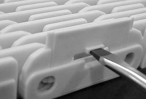
35 Engineering Manual MatTop Chains Conveyor Design 500-series Place screwdriver in rectangular hole. Remove open clip by pushing and turning screwdriver series Place screwdriver in oblong hole of the clip. Turn clip counter clock wise to open it series Place screwdriver in oblong hole of the clip. Turn clip counter clock wise to open it series Place screwdriver in rectangular hole. Remove open clip by pushing and turning screwdriver. EM-MT-17
36 Engineering Manual MatTop Chains Conveyor Design Ispection of modular belts A good condition of the line can be maintained when people recognise signs of initial wear/ failure and react accordingly. Following aspects are of importance during regular check-up. Check the condition of the chain/ belt regularly, and replace links/ modules which are damaged. Important in this matter is to try to find the cause of the damaged links/ modules. Wear patterns or damage on a chain or belt can often lead you to a problem area elsewhere in the conveyor. Check the amount of catenary sag and remove links or modules when the catenary of the chains exceeds prescriptions. Remember catenary could be larger under load. Check if the returnrollers turn freely, repair or replace if not; Remove dirt and debris which is stuck in the grid of the belt or inbetween the chain/ belt and the conveyor construction. In case of lubrication check if the lubrication system operates properly. Check carryways and wear strips for excessive wear or peculiar wear patterns. Check positions of transfer plates and check the fingerplates for broken/ worn parts and repair or replace if necessary. Note: It is very important to replace damaged modules in plastic belts and links in plastic chains as soon as possible since small damage could lead to bigger damage if it is not repaired. If any damage is found such as pieces of plastic broken off, or a wear pattern at the side of the belt, the cause of the problem should be located. EM-MT-18
37 Engineering Manual MatTop Chains Conveyor Design Cleaning instructions To be able to keep production lines running at highest efficiency, cleaning is most important. Cleaning should include the removal of grease, dirt, dust and bacteria from the chain/ belt and the components. Cleaning is importance because it gives the following results: Disinfecting results in a hygienic system Products will be cleaner when they are packed Reduction of friction between chains/belts and products results in less tipping products and less wear. Removal of abrasive particles for longer wear life and components. Note: It is recommended always to flush the chain/ belts with plenty of water after having the chains/ belts cleaned, to remove the cleaning agent from the conveyor. Cleaning dry running conveyors With dry running conveyors there is no continuous cleaning like with lubricated conveying. All products (beer or lemonade) spilled on the chain/ belt will result in pollution of the containers, increasing the friction, and the risk of products toppling over. The main indicator for the necessity of cleaning is the increase of friction, which negatively affects the product flow. The required intervals for cleaning depend on the product type that is being filled, the stability of the product and the position in the line. For example: a conveyor next to a filler needs to be cleaned more often, compared to a mass handling conveyor near the palletizer. In case of product spillage on the tracks, it is recommended to remove this as soon as possible in order to prevent drying up, preferable by rinsing with warm softened water. The run dry conveyors in the most critical sections of a line should be cleaned daily to obtain maximum sanitation and performance. At the very imum, rinse daily and thoroughly sanitize weekly. Partially Lubricated Lines should thoroughly sanitized these on a weekly basis. Methods of cleaning 1. Periodic high pressure hot water rinse or steam cleaning should prove satisfactory. Spray the chain/belt in place on each conveyor, both on the carry and in the return sections. For easy access to the undersides of the chains/belts in the carry and return ways, some manufacturers provide clean-out holes in the side frames. 2. Warm water and mild soap are commonly used to clean the conveyors. 3. Foag agents or other chemical cleaners may be used if they are compatible with conveyor materials (see General Guidelines, item 4). Carefully follow the instructions provided by the manufacturer to detere proper concentration of solutions and proper, safe use and disposal. Note: Keep water, steam and chemicals away from electrical disconnects, motors, photo eyes, etc. 4. In extreme situations, it may be necessary to periodically clean the chains/belts with a bristle brush. Clean the chain/belt in place on the conveyor, both on the carry and in the return sections. 5. When running dry after a period, fine wear-dust can arise, cog from the wearstrips, curves and/or chain/belt. Remove this dust periodically with cloth or vacuum cleaner. Note: Note: The main objective is to clean the chain/belt carrying surface and underside as well as the wearstrips and tracks. Inspect conveyors often. Remove broken or jammed containers or pieces of containers as soon as they are detected. Use cleaning solutions to clean away excessive spillage. EM-MT-19
 Surface Bottom 500-series 1 mm 1 mm 1500-series 1 mm 1 mm 505-series 1.5 mm 1.")
38 Engineering Manual MatTop Chains Conveyor Design Belt replacement Belts have to be replaced if the thickness of the belts is reduced unacceptably. In the table below guidelines are shown regarding replacement criteria. Belt type Max wear (mm) Surface Bottom 500-series 1 mm 1 mm 1500-series 1 mm 1 mm 505-series 1.5 mm 1.5 mm 1000-series 1 mm 1 mm 1005-series 1.5 mm 1.5 mm 1255-series 1.5 mm 1.5 mm 2000-series 2 mm 2 mm 2500-series 3 mm 3 mm In practice, the product handling will dictate whether the surface wear is acceptable or not. If wear at the top or bottom surface results in product tippage, replacement is eent. 3% elongation of the pitch, is the ultimate elongation limit of belts. Further elongation causes the belt jumping on the sprockets under load. Note: When replacing chains or belts always replace the wearstrips, the sprockets and idlers as well Sprocket & idler replacement The teeth show a hookshape, which obstructs the chain. Also replace sprockets when teeth are damaged or when chain jumps on the sprocket. The idler is oscillating on the shaft, because of a worn bore If belt is replaced due to elongation, always install new sprockets! Note: When replacing sprockets on multiple track conveyors, make sure all sprockets are mounted in the same position on the shaft. Wearstrip replacement When chains are replaced always replace the wearstrips. Dirt or debris is embedded in the wearstrip material in unacceptable amounts EM-MT-20
39 Engineering Manual Sideflexing Belts Sideflexing Belts M Basic design considerations Side flexing configuration When planning the side-flexing conveyor layout, the designer must consider the following factors that affect chain life: Minimize the number of corners in each conveyor whenever possible When conveying from point A to point B, design the conveyors so that the last curve is positioned furthest from the last drive (see drawing), resulting in lower chain tension and maximizing chain life A Tail shaft A Tail shaft Drive shaft B Drive shaft B Preferred Avoid End drive construction These conveyors have the drive-motor and sprocket at the end of the conveyor. End-drive conveyor End-drive conveyor & snub roller C should be mm Centre-drive conveyor Wrap around angle Recommended wrap angle on sprockets is: 140º +/- 10º. When the wrap angle is too small, the sprocket will not be able to transfer the load to the chain anymore causing the chain/belt to jump on the sprockets. When the wrap angle is too big, the chain/belt can stick to the sprocket. EM-SF-01
40 Engineering Manual Sideflexing Belts Sideflexing Belts Catenary sag It is recommended to create a catenary sag which provides a complete discharge of the load on the belt. type A (mm) B (mm) Vertical sag Y(mm) 505-series series series series series series The right vertical catenary sag can usually be obtained automatically by just pulling both ends of the belt together and connecting them. The catenary sag will increase due to elevated temperatures. Furthermore, the belt can elongate due to strain and wear of the pins and hinge eyes. Therefore it is important to check and adjust the catenary regularly. End drive with tensioner Centre drive with tensioner A tensioner construction is only necessary if the conveyor design does not allow a proper catenary sag due to lack of space. A tensioner can also be used with declined conveyors, but in all other cases it is not recommend to tension the chain/belt. NOTE: The tensioner roller/sprocket can be fixed on an arm or move up and down in slots in the conveyor sideplates. Maximum speed sideflexing belts The maximum speed of a sideflexing belt depends on the PV-value of the curve. This PV-value represents a combination of pressure and velocity with a specific limit. Please contact application engineering if you require support in detering the PV-limit and maximum speed of an application. A maximum speed of 40 m/ is recommended. For higher speeds please contact application engineering. EM-SF-02
41 Engineering Manual Sideflexing Belts Sideflexing Belts Roller diameter for sideflexing belts Belttype 505- series series series series series series Idler rollers All dimensions in mm >30 >60¹ >60¹ >60¹ >60¹ Depends on execution Return rollers Backflex rollers > 30 > 80 > 80 > 80 > 80 > 300 ¹ For long conveyors with high load we recommend to use a roller with a diameter of 80mm. The recommended roller diameters in the table are an indication. The width of the conveyor is not taken into account. The diameter of the shaft should be large enough to avoid excessive deflection of the roller. At the same time it is recommended not to exceed the maximum diameter, because the roller friction may be too heavy to be set in motion by the belt. Position sprocket - wearstrips When the belts enter the sprocket, it tends to rise and fall slightly (chordal action). For this reason the sprockets should be mounted in such a way that their highest point is no higher than the top of the wearstrips. The front edges of the wearstrips should be chamfered to allow smooth and free running of the chain. The distance from the end of the wearstrip to the sprocket shaft centerline should equal dimension L, otherwise the wearstrip will interfere with the free articulation of the chain as it enters the sprockets. Belt type 505-series 1255-series 1265-series 1275-series 1285-series 7956-series Drive sprocket H (mm) L mm Idler roller H (mm) L mm EM-SF-03 MCC Engineering Manual
42 Engineering Manual Sideflexing Belts Keyway dimensions of MCC sprockets Sideflexing Belts d1 (mm) b (mm) t (mm) d1 (inch) b (inch) t (inch) 25mm " 1/4 1 1/8 30mm /4" 1/4 1 3/8 35mm /2" 3/8 1 9/16 40mm /4" 3/8 1 15/16 45mm " 1/2 2 1/4 50mm mm Wearstrip materials Stainless steel wearstrips Can be used in most situations using plastic belts and are strongly recommended in abrasive environments. Recommended for abrasive conditions due to avoiding of dirt embedding in the wearstrips; Recommended for plastic chains/belts in dry environments with speeds > 40m/; Cold rolled stainless steel with a hardness of at least 25 Rc and a surface finish of maximum 1.6 µm is recommended; Best results can be achieved by using stainless steel AISI 431 (Werkstoff-Nr material; soft AISI 304 (Werkstoff-Nr ) is not recommended as wearstrip material. UHMWPE / ULF wearstrips Friction is low compared to steel wearstrips. Two types of plastic are suitable to be used as a wearstrip material. Most common used wearstrip material with extreme low friction; Excellent resistance against many chemicals; Virtually no moisture absorption, therefore very suitable for lubricated lines; Good dimension stability; Reduces some of the noise conveyors produce; Suitable for dry running conveyors with speeds up to 40 m/ (UHMWPE) or up to 60 m/ (ULF); Extruded quality 1000 grade UHMWPE is recommended. Recommended wearstrip materials Wearstrip material Plastic modular belts Dry Lubr. UHMWPE / ULF + + Polyamide +/- - Stainless steel Recommended +/- Satisfactory - Not recommended 1) Up to 60 m/ in non abrasive conditions 2) Only in non abrasive conditions MCC Engineering Manual Belt return For sideflexing belts we recommend to use rotating rollers for the returnpart to reduce wear. Simple construction. Good accessibility EM-SF-04 Only point contact between chain/ belt and roller. Small rollers may cause a rattling sound. Rollers should rotate freely therefore, rollers with rubber cover are recommended.
43 Engineering Manual Sideflexing Belts RBP 505-Series Beltstyle RBP 505-series Minimum backflex diameter: Minimum end roller diameter: 30mm 30mm Lay-out Guidelines A A Drive B B D C Idler C D * For centre-drive add 200mm. Minimum straight section drive side* For belt width <500mm: imal 500mm. For belt width >500mm: imal belt width. Minimum straight in between 2 curves (S-bend) 1.5 x belt width Minimum straight section idler side 500mm Minimum inside radius 2 x belt width MCC guiding Profile RBP 505-series The MCC guiding profile should be used to guide the belt through the curve. Material of the guiding strip is special polyamide, which offers low friction and high wear resistance. Standard: Codenr (length of 3m, MCC 3500) FDA-approved: Codenr (length of 2m, MCC 3600) ULF: Codenr (length of 3m, MCC 4000) Straight section RBP 505-series Below a cross section drawing is shown with recommended straight section construction Please make sure there is enough space between belt and conveyor / surrounding area. Sideguides can prevent the belt from touching the conveyor sheet, especially after the curves. EM-SF-05
44 Engineering Manual Sideflexing Belts RBP 505-Series Curve section RBP 505-series Below a cross section drawing is shown with recommended curve construction Sprocket positions RBP 505-series Outside Radius Inside Radius Belt Nr. of sprockets width Drive Idler 170 mm mm mm mm mm mm mm 10 8 Roller dimension RBP 505-series Rollers should rotate freely at all times; therefore we strongly recommend to equip the rollers with bearings. *) For high loads (>500 N) or wide belts (>510 mm) use bigger shaft diameter and/ or support the shaft in the centre Additional Notes Complete machined UHMPWE curves including curve profiles are available in any angle and for any belt width. Please note that the catenary sag can increase under load. Make sure the belt cannot catch against the sideframe in the retourpart taking increased catenary into account. EM-SF-06
45 Engineering Manual Sideflexing Belts RB 1255-Series Beltstyle RB 1255-series Minimum backflex diameter: Minimum end roller diameter: 60mm 60mm Lay-out Guidelines A Drive B D Idler C A B C D Minimum straight section drive side 750mm with normal drive, 500mm width gravity tensioner. Minimum straight in between 2 curves (S-bend) 1.5*belt width Minimum straight section idler side 500mm Minimum inside radius 2 * belt width Recommended guiding Profile dimensions for RB 1255-series The guiding profile should be used to guide the belt through the curve. We recommend to use a c-profile according to the drawings dimension. Recommended material of the guiding strip is Nylatron special polyamide, which offers low friction and high wear resistance. UHMWPE can also be used. Straight section RB 1255-series Below a cross section drawing is shown with recommended straight section construction Curve section RB 1255-series EM-SF-07
46 Engineering Manual Sideflexing Belts RB 1255-Series Below a cross section drawing is shown with recommended curve construction Sprocket positions RB 1255-series Outside Radius Inside Radius Belt Nr. of sprockets width Drive Idler 170 mm mm mm mm mm mm mm 10 8 Inside Radius Outside Radius Roller dimension RB 1255-series Rollers should rotate freely at all times; therefore we strongly recommend to equip the rollers with bearings. EM-SF-08
47 Engineering Manual Sideflexing Belts RBP 1255-Series Beltstyle RBP 1255-series Minimum backflex diameter: Minimum end roller diameter: 60mm 60mm Lay-out Guidelines A Drive B D Idler C A B C D Minimum straight section drive side 750mm with normal drive, 500mm width gravity tensioner. Minimum straight in between 2 curves (S-bend) 1.5 * beltwidth Minimum straight section idler side 500mm Minimum inside radius 2 * beltwidth MCC guiding Profile RBP 1255-series The MCC guiding profile should be used to guide the belt through the curve and along the frame. There are 2 materials available: MCC3500: Special polyamide MCC4000: Ultra Low Friction UHMWPE Profile for curve: Standard: Codenr (length of 3m, MCC3500) ULF: Codenr (length of 3m, MCC4000) Profile for frame: Standard: Codenr (length of 1.8m, MCC3500) ULF: Codenr (length of 3m, MCC4000) Straight section RBP 1255-series Below a cross section drawing is shown with recommended straight section construction EM-SF-09
48 Engineering Manual Sideflexing Belts RBP 1255-Series Curve section RBP 1255-series Below a cross section drawing is shown with recommended curve construction Also completely machined UHMWPE curves are available in any angle and for any belt width. Sprocket positions RBP 1255-series Outside Radius Inside Radius Belt Nr. of sprockets width Drive Idler 170 mm mm mm mm mm mm mm 10 8 Inside Radius Outside Radius Roller dimension RBP 1255-series Rollers should rotate freely at all times; therefore we strongly recommend to equip the rollers with bearings. EM-SF-10
49 Engineering Manual Sideflexing Belts RBT 1255-Series Beltstyle RBT 1255-series Minimum backflex diameter: Minimum end roller diameter: 60mm 60mm Lay-out Guidelines A Drive B D Idler C A B C D Minimum straight section drive side 750mm with normal drive, 500mm width gravity tensioner. Minimum straight in between 2 curves (S-bend) 1.5*belt width Minimum straight section idler side 500mm Minimum inside radius 2 * belt width Recommended guiding Profile dimensions for RBT 1255-series The MCC guiding profile should be used to guide the belt through the curve and along the frame. There are 2 materials available: MCC3500: Special polyamide MCC4000: Ultra Low Friction UHMWPE Standard: Codenr (length of 3m) ULF: Codenr (length of 3m) Straight section RBT 1255-series Below a cross section drawing is shown with recommended straight section construction *) For the returnpart, also rotating rollers can be used. EM-SF-11
50 Engineering Manual Sideflexing Belts RBT 1255-Series Curve section RBT 1255-series Below a cross section drawing is shown with recommended curve construction Sprocket position RBT 1255-series Outside Radius Inside Radius Belt Nr. of sprockets width Drive Idler 170 mm mm mm mm mm mm mm 10 8 Outside Radius Inside Radius Roller dimension RBT 1255-series Rollers should rotate freely at all times; therefore we strongly recommend to equip the rollers with bearings. Additional Notes Complete machined UHMWPE curves including curve profiles are available in any angle and for any belt width EM-SF-12
51 Engineering Manual Sideflexing Belts RBT 1265-Series Beltstyle 1265-series Minimum backflex diameter: Minimum end roller diameter: 60mm 60mm Lay-out Guidelines B D C A Idler Drive A B C D Minimum straight section drive side 750mm with normal drive, 500mm width gravity tensioner. Minimum straight in between 2 curves (No S-bend!) No imum straight needed Minimum straight section idler side 500mm Minimum inside radius 2 * belt width MCC guiding Profile 1265-series The MCC guiding profile should be used to guide the belt through the curve and along the frame. There are 2 materials available: MCC3500: Special polyamide MCC4000: Ultra Low Friction UHMWPE Profile for curve: Standard: Codenr (length of 2.8m, MCC3500) ULF: Codenr (length of 2.8m, MCC4000) Profile for frame: Standard: Codenr (length of 1.8m, MCC3500) Straight section 1265-series Below a cross section drawing is shown with recommended straight section construction EM-SF-13
52 Engineering Manual Sideflexing Belts RBT 1265-Series Curve section 1265-series Below a cross section drawing is shown with recommended curve construction Also completely machined UHMWPE curves are available in any angle and for any belt width. Sprocket position RBT 1265-series Outside Radius Inside Radius Belt Nr. of sprockets width Drive Idler 170 mm mm mm mm mm mm mm 9 8 Roller dimension 1265-series Rollers should rotate freely at all times; therefore we strongly recommend to equip the rollers with bearings. *) For high loads (>500 N) or wide belts (>510 mm) use bigger shaft diameter and / or support the shaft in the centre Additional Notes To reduce friction in the curve section, we can also offer machined curves with roller bearing inserts. Please ask our Engineering for further information. We recommend to use roller with 80mm diameter for heavy duty applications. EM-SF-14
53 Engineering Manual Sideflexing Belts RBP 1275-Series Beltstyle RBP 1275-series Minimum backflex diameter: Minimum end roller diameter: 60mm 60mm Lay-out Guidelines B A Minimum straight section drive side 750mm with normal drive, 500mm width gravity tensioner. B Minimum straight in between 2 curves (No S-bend!) D No imum straight needed A C C Minimum straight section idler side Idler Drive D 500mm Minimum inside radius ( R) Belt width Min. radius Belt width Min. radius MCC guiding Profile RBP 1275-series The MCC guiding profile should be used to guide the belt through the curve and along the frame. There are 2 materials available: MCC3500: Special polyamide MCC4000: Ultra Low Friction UHMWPE Profile for curve: Standard: Codenr (length of 3m, MCC3500) ULF: Codenr (length of 3m, MCC4000) Profile for frame: Standard: Codenr (length of 1.8m, MCC3500) ULF: Codenr (length of 3m, MCC4000) Straight section RBP 1275-series Below a cross section drawing is shown with recommended straight section construction EM-SF-15
54 Engineering Manual Sideflexing Belts RBP 1275-Series Curve section RBP 1275-series Below a cross section drawing is shown with recommended curve construction Sprocket positions RBP 1275-series Outside Radius Inside Radius Belt Nr. of sprockets width Drive Idler 170 mm mm mm mm mm mm mm 10 8 Inside Radius outnside Radius Roller dimension RBP 1275-series Rollers should rotate freely at all times; therefore we strongly recommend to equip the rollers with bearings. *) For high loads (>500 N) or wide belts (>510 mm) use bigger shaft diameter and/ or support the shaft in the centre Additional Notes We recommend to use the MCC machined corner tracks, which allow a simple design and a trouble-free operation. EM-SF-16 Engineering Manual MatTop Chains
55 Engineering Manual Sideflexing Belts RBT 1275-Series Beltstyle RBT 1275-series Minimum backflex diameter: Minimum end roller diameter: 60mm 60mm Lay-out Guidelines B D A C Idler Drive A Minimum straight section drive side 750mm with normal drive, 500mm width gravity tensioner. B Minimum straight in between 2 curves (No S-bend!) No imum straight needed C Minimum straight section idler side 500mm D Minimum inside radius ( R) Belt width Min. radius Belt width Min. radius MCC guiding Profile RBT 1275-series The MCC guiding profile should be used to guide the belt through the curve and along the frame. There are 2 materials available: MCC3500: Special polyamide MCC4000: Ultra Low Friction UHMWPE Standard: Codenr (length of 3m) ULF: Codenr (length of 3m) Straight section RBT 1275-series Below a cross section drawing is shown with recommended straight section construction EM-SF-17
56 Engineering Manual Sideflexing Belts RBT 1275-Series Curve section RBT 1275-series Below a cross section drawing is shown with recommended curve construction Sprocket position RBT 1275-series Outside Radius Inside Radius Belt Nr. of sprockets width Drive Idler 170 mm mm mm mm mm mm mm 10 8 Inside Radius Outside Radius Roller dimension 1275-series Rollers should rotate freely at all times; therefore we strongly recommend to equip the rollers with bearings.. *) For high loads (>500 N) or wide belts (>510 mm) use bigger shaft diameter and/ or support the shaft in the centre EM-SF-18
57 Engineering Manual Sideflexing Belts RBT 1285-Series Belt style RBT 1285-series Minimum backflex diameter: Minimum end roller diameter: 60mm 60mm Lay-out Guidelines B A Minimum straight section drive side 750mm with normal drive, 500mm width gravity tensioner. B Minimum straight in between 2 curves (No S-bend!) D No imum straight needed A C C Minimum straight section idler side Idler Drive D 500mm Minimum inside radius ( R) Belt width Min. radius Belt width Min. radius MCC guiding Profile RBT 1285-series The MCC guiding profile should be used to guide the belt through the curve and along the frame. There are 2 materials available: MCC3500: Special polyamide MCC4000: Ultra Low Friction UHMWPE Profile for curve: Standard: Codenr (length of 2.8m, MCC3500) ULF: Codenr (length of 2.8m, MCC4000) Profile for frame: Standard: Codenr (length of 1.8m, MCC3500) Straight section RBT 1285-series Below a cross section drawing is shown with recommended straight section construction EM-SF-19
58 Engineering Manual Sideflexing Belts RBT 1285-Series Curve section RBT 1285-series Below a cross section drawing is shown with recommended curve construction Also completely machined UHMWPE curves are available in any angle and for any belt width. Sprocket position RBT 1285-series Outside Radius Inside Radius Belt Nr. of sprockets width Drive Idler 170 mm mm mm mm mm mm mm 9 8 Roller dimension RBT 1285-series Rollers should rotate freely at all times; therefore we strongly recommend to equip the rollers with bearings. Additional Notes Complete machined UHMWPE curves including curve profiles are available in any angle and for any belt width We recommend to use rollers with 80mm diameter for heavy duty applications. EM- SF-20


59 Engineering Manual Sideflexing Belts Sideflexing Belts Installation instructions 505-series Turn screwdriver counter clockwise to remove clip. Place screwdriver between clip and belt end. Please note that 505-series belts have a specific running direction, indicated by the arrow at the bottom series belt Lift belt out of tracks and position belt on the lugs. Now, push one belt module downwards. Place screwdriver in opposite end hole and push pin out series belt Turn screwdriver counter clockwise to open clip. Place screwdriver in opposite end hole and push pin out. EM-SF-21 MCC Engineering Manual
60 Engineering Manual Sideflexing Belts Engineering C Sideflexing Belts 1275-series belt Lift belt out of tracks and position belt on the lugs. Now, push one belt module downwards. Place screwdriver in opposite end hole and push pin out series belt Turn screwdriver counter clockwise to open clip. Place screwdriver in opposite end hole and push pin out. MCC Engineering Manual EM-SF-22
61 MCC Sideflexing Belts Engineering
62 Engineering Manual Material Index Materials MCC Material Prefix Description Page Primary Components FDA Approved AS Anti-Static MA 1 Electrically conductive acetal (POM) No BHT Blue High Temperature MA 12 Polypropylene (PP) Yes BLT Blue Low Temperature MA 15 Polyethylene (HDPE) Yes BRSM Black Cut Resistance with Red Links MA 2 Cut and abrasive wear resistant acetal (POM) Yes BSM Black Cut Resistance MA 28 Cut and abrasive wear resistant acetal (POM) Yes BUV Blue Acetal Ultraviolet Resistant MA 5 Ultraviolet resistant acetal (POM) No BYSM Black Cut Resistance with Yellow Links MA 2 Cut and abrasive wear resistant acetal (POM) Yes CR Extreme Chemical Resistant MA 3 Fluorinated polymer Yes D Plain Acetal MA 4 Acetal (POM) No DUV Plain Acetal Ultraviolet Resistant MA 5 Ultraviolet resistant acetal (POM) No EPDM Ethylene Propylene Rubber MA 6 Ethylene propylene rubber No FR Flame Retardant MA 7 Flame retardant polyester (PBT) No FR-ESD Flame Retardant Electrostatic Dissipative MA 33 High capacity electrostatic dissipative acetal (POM) No GTC Grey Tough Composite MA 8 High strength, impact modified composite No HCAS High Capacity Anti-static (Black) MA 32 High capacity Anti-static acetal (POM) No HP High Performance MA 9 High performance, internally lubricated acetal (POM) Yes HS Heat Stabilized MA 11 Heat stabilized nylon (PA) No HT High Temperature MA 12 Polypropylene (PP) Yes HTB Black High Temperature MA 12 Polypropylene (PP) Yes KHT Khaki High Temperature MA 12 Polypropylene (PP) Yes LF Low Friction MA 14 Low friction acetal (POM) Yes LT Low Temperature MA 15 Polyethylene (HDPE) Yes MR Melt Resistant MA 16 Melt resistant nylon (PA) No Neoprene Neoprene MA 17 Neoprene No P Chemical Resistant MA 18 Polyester (PBT) Yes PS Platinum Series MA 19 High speed, Platinum Series internally lubricated acetal (POM) Yes PSX Platinum Series MA 20 High speed, Platinum Series internally lubricated acetal (POM) Yes RHT Red High Temperature MA 12 Polyethylene (HDPE) Yes RSM Red Cut Resistant MA 28 Cut and abrasive wear resistant acetal (POM) Yes RUV Red Acetal Ultraviolet Resistant MA 5 Ultraviolet resistant acetal (POM) No S Carbon Steel MA 21 Carbon Steel No SMB Blue Cut Resistant MA 28 Cut and abrasive wear resistant acetal (POM) Yes SRMB Blue Cut Resistant with Red End Links MA 22 Cut and abrasive wear resistant acetal (POM) Yes SS Stainless Steel MA 22 Austenitic stainless steel Yes SSB Stainless Steel Low Magnetic MA 23 Low ferromagnetic austenitic stainless steel Yes SYMB Blue Cut Resistant with Yellow End Links MA 2 Cut and abrasive wear resistant acetal (POM) Yes USP Ultra Stabilized Polypropylene MA 27 Polypropylene (PP) and chemical stabilizers Yes WD White Plain Acetal MA 4 Acetal (POM) No WHP White High Performance MA 9 High performance, internally lubricated acetal (POM) Yes WHT White High Temperature MA 12 Polypropylene (PP) Yes WLF White Low Friction MA 14 Low friction acetal (POM) Yes WLT White Low Temperature MA 15 Polyethylene (HDPE) Yes WSM White Cut Resistant MA 28 Cut and abrasive wear resistant acetal (POM) Yes XLA Internally Lubricated Polyacetal (Grey) MA 30 Internally lubricated polyacetal (POM) Yes XLG Low Friction Acetal (Green) MA 31 Internally lubricated polyacetal (POM) Yes YSM Yellow Cut Resistant MA 28 Cut and abrasive wear resistant acetal (POM) Yes YUV Yellow Acetal Ultraviolet Resistant MA 5 Ultraviolet resistant acetal (POM) No MCC Engineering Manual
63 AS Materials Rexnord Anti-Static Material Brief Description Formulated to reduce or eliate nuisance static buildup that can occur while conveying products or during product accumulation. Used to dissipate nuisance sparks for Class II type static environments only. Please contact Application Engineering at for specific uses for this material. Primary Components Electrically conductive acetal (POM) General Information Temperature Fahrenheit Celsius FDA Prefix Material max max Approval dry wet dry wet AS Anti-Static (Black) NR NR No Friction Factors Between Material and Product Product Material Returnable Glass Non-Returnable Plastic (crates, Condition Aluum Paper PET Steel Bottles** Glass Bottles shrink wrap, etc) Dry Water NR NR NR NR NR NR NR Soap and Water NR NR NR NR NR NR NR Oil NR NR NR NR NR NR NR Friction Factors Between Material and Wearstrips Wearstrip Material Carbon and Condition UHMWPE Nylatron Stainless Steel Dry Water NR NR NR Soap and Water NR NR NR Oil NR Regulatory Information Rexnord and TableTop are trademarks of Rexnord Corporation. All rights reserved. Nylatron is a registered trademark of Quadrant Engineering Plastics Products. NR denotes "not recommended", Dash denotes "combination not tested" 1. Types of Static Environments: Class I: Static spark causes explosion. Use stainless steel chain materials. Class II: Static spark is a nuisance charge causing slight shock, possible circuit damage or electrical malfunction. 2. Electrical Properties: Surface resistivity = 10 3 Ω/sq. 3. Wearstrip Recommendations: Wearstrips must be grounded to the conveyor frame and must be electrically conductive to be effective. The conveyor frame should also be externally grounded. 4. Strength Considerations: Rexnord TableTop & MatTop Chains molded from anti-static material must be derated 40% from their acetal counterparts. Pressure-Velocity (PV) Limits: PV Limit of Rexnord TableTop Chains molded from anti-static material must be derated 40% from acetal materials. PV Limits relate to the speed and tension exerted as the chain travels around the corners. 5. Depending on application requirements, the entire conveyor chain can be comprised of anti-static material or sections of antistatic material can be interspersed at various intervals. 6. AS friction factor should be used when interspersing AS links into any other material. **Friction of returnable bottles will vary depending on the quality of the glass, the amount of roughed up surface, etc. AS EM - MA - 1
 only assembled in the same chain.")
64 BRSM BYSM SRMB SYMB BRSM BYSM SRMB Materials SYMB Brief Description Automotive handling applications require chains to be assembled with different color end links to provide contrast. These are the same chain modules molded in wear and cut resistant materials (BSM, SMB, RSM and YSM) only assembled in the same chain. Can be used in both dry and wet conditions and in applications where abrasive wear due to products or environment is a concern. Has good impact resistance and is as strong as standard acetal materials. Primary Components Cut and abrasive wear resistant acetal (POM) General Information Temperature Fahrenheit Celsius FDA Prefix Material max max Approval dry wet dry wet BRSM Black Cut Resistant with Red End Links Yes BYSM Black Cut Resistant with Yellow End Links Yes SRMB Blue Cut Resistant with Red End Links Yes SYMB Blue Cut Resistant with Yellow End Links Yes Rexnord Cut Resistant Material Friction Factors Between Material and Product Product Material Returnable Glass Non-Returnable Plastic (crates, Condition Aluum Paper PET Steel Bottles** Glass Bottles shrink wrap, etc) Dry Water NR NR NR NR NR NR NR Soap and Water NR NR NR NR NR NR NR Oil NR Friction Factors Between Material and Wearstrips Wearstrip Material Carbon and Condition UHMWPE Nylatron Stainless Steel Dry Water Soap and Water Oil Regulatory Information The Food and Drug Adistration (FDA) accepts certain materials for direct food contact. FDA approved material is compliant to FDA 21 CFR 177. Rexnord is a trademark of Rexnord Corporation. All rights reserved. Nylatron is a registered trademark of Quadrant Engineering Plastics Products. NR denotes "not recommended", Dash denotes "combination not tested" EM - MA Not available for Rexnord TableTop and Multiflex chains. **Friction of returnable bottles will vary depending on the quality of the glass, the amount of roughed up surface, etc.
 376-4800 for specific uses for this material.")
65 CR Materials Rexnord Extreme Chemical Resistant Material Brief Description Able to withstand nearly any harsh chemical environment, including applications where strong oxidizing agents, acids and bases such as sodium hydroxide, sulfuric acid, hydrochloric acid, hydrofluoric acid and iodine are present. Please contact Rexnord at (262) for specific uses for this material. Primary Components Fluorinated polymer General Information Temperature Fahrenheit Celsius FDA Prefix Material max max Approval dry wet dry wet CR Extreme Chemical Resistant (White) Yes Friction Factors Between Material and Product Product Material Returnable Glass Non-Returnable Plastic (crates, Condition Aluum Paper PET Steel Bottles** Glass Bottles shrink wrap, etc) Dry Water NR Soap and Water NR Oil NR Friction Factors Between Material and Wearstrips Wearstrip Material Carbon and Condition UHMWPE Nylatron Stainless Steel Dry Water Soap and Water Oil Regulatory Information The Food and Drug Adistration (FDA) accepts certain materials for direct food contact. FDA approved material is compliant to FDA 21 CFR 177. Rexnord and TableTop are trademarks of Rexnord Corporation. All rights reserved. Nylatron is a registered trademark of Quadrant Engineering Plastics Products. 1. Strength Considerations: Rexnord TableTop Chains molded from extreme chemical resistant material (with stainless steel pins) must be derated 20% from their acetal counterparts (with stainless steel pins). Rexnord TableTop Chains molded from extreme chemical resistant material (with plastic pins) must be derated 40% from their acetal counterparts (with stainless steel pins). Rexnord MatTop Chains molded from extreme chemical resistant material must be derated 20% from their acetal counterparts. Pressure-Velocity (PV) Limits: PV Limit of Rexnord TableTop Chains molded from extreme chemical resistant material must be derated 20% from acetal materials. PV Limits relate to the speed and tension exerted as the chain travels around the corners. NR denotes "not recommended", Dash denotes "combination not tested" **Friction of returnable bottles will vary depending on the quality of the glass, the amount of roughed up surface, etc. EM - MA - 3 CR
66 D WD Rexnord Plain Acetal Material D Brief Description A general-purpose conveyor chain material which has low friction, high strength, excellent wear life, superior fatigue resistance and is chemical resistant in a wide range of environments. Regulatory Information NR denotes "not recommended", Dash denotes "combination not tested" Primary Components Acetal (POM) General Information Temperature Fahrenheit Celsius FDA Prefix Material max max Approval dry wet dry wet D Plain Acetal (Gray) No WD White Plain Acetal No DBM Dark Blue Material No GM Gray Material No RM Red Material No YM Yellow Material No Friction Factors Between Material and Product Product Material Returnable Glass Non-Returnable Plastic (crates, Condition Aluum Paper PET Steel Bottles** Glass Bottles shrink wrap, etc) Dry Water NR Soap and Water NR Oil NR Friction Factors Between Material and Wearstrips Wearstrip Material Carbon and Condition UHMWPE Nylatron Stainless Steel Dry Water Soap and Water Oil The Food and Drug Adistration (FDA) accepts certain materials for direct food contact. FDA approved material is compliant to FDA 21 CFR 177. Rexnord is a trademark of Rexnord Corporation. All rights reserved. Nylatron is a registered trademark of Quadrant Engineering Plastics Products. EM - MA - 4 WD RM DBM YM GM **Friction of returnable bottles will vary depending on the quality of the glass, the amount of roughed up surface, etc. Materials
67 DUV BUV RUV YUV Materials Rexnord Plain Acetal Ultraviolet Resistant Material Brief Description Primary Components Formulated to reduce or eliate material degradation in applications where ultraviolet radiation exposure is a concern. Retains its mechanical integrity when exposed to direct sunlight (outdoor applications) as well as in applications that use ultraviolet radiation to run a process. Has the same strength and wear properties as plain acetal material. Ultraviolet resistant acetal (POM) General Information Temperature Fahrenheit Celsius FDA Prefix Material max max Approval dry wet dry wet DUV Acetal Ultraviolet Resistant (Black) No BUV Blue Acetal Ultraviolet Resistant No RUV Red Acetal Ultraviolet Resistant No YUV Yellow Acetal Ultraviolet Resistant No Friction Factors Between Material and Product Product Material Returnable Glass Non-Returnable Plastic (crates, Condition Aluum Paper PET Steel Bottles** Glass Bottles shrink wrap, etc) Dry Water NR Soap and Water NR Oil NR Friction Factors Between Material and Wearstrips Wearstrip Material Carbon and Condition UHMWPE Nylatron Stainless Steel Dry Water Soap and Water Oil Regulatory Information Rexnord is a trademark of Rexnord Corporation. All rights reserved. Nylatron is a registered trademark of Quadrant Engineering Plastics Products. NR denotes "not recommended", Dash denotes "combination not tested" **Friction of returnable bottles will vary depending on the quality of the glass, the amount of roughed up surface, etc. EM - MA - 5 BUV YUV RUV DUV
 for different applications.")
68 EPDM Rexnord EPDM Material EPDM (Black) Brief Description EPDM is used as a gripper material that has outstanding resistance to oxygen and ozone. It also has good resistance to the very hot water used in many SideGrip rinser applications. It is available in several different durometers (or hardness) for different applications. Regulatory Information NR denotes "not recommended", Dash denotes "combination not tested" Primary Components General Information Temperature Fahrenheit Celsius FDA Prefix Material max max Approval dry wet dry wet - EPDM No Friction Factors Between Material and Product Product Material Returnable Glass Non-Returnable Plastic (crates, Condition Aluum Paper PET Steel Bottles** Glass Bottles shrink wrap, etc) Dry NR NR NR NR NR NR NR Water NR NR NR NR NR NR NR Soap and Water NR NR NR NR NR NR NR Oil NR NR NR NR NR NR NR Friction Factors Between Material and Wearstrips Wearstrip Material Carbon and Condition UHMWPE Nylatron Stainless Steel Dry NR NR NR Water NR NR NR Soap and Water NR NR NR Oil NR NR NR Rexnord, TableTop and MatTop is a trademark of Rexnord Corporation. All rights reserved. Nylatron is a registered trademark of Quadrant Engineering Plastics Products. EM - MA - 6 Ethylene Propylene Rubber EPDM (White) This material is not available in TableTop, MatTop, or Multiflex chains. It is only available as a gripper material for SideGrip chains. 2. The temperature range for standard 50 shore EPDM grippers. Other hardnesses will affect the operating temperature. 3. Color may be black or white depending on chain series. See specific chain series in 4. Product Catalog for color. **Friction of returnable bottles will vary depending on the quality of the glass, the amount of roughed up surface, etc. Materials
69 FR Brief Description Formulated to eliate the possibility of sustained combustion should the chain be accidentally ignited. Will self extinguish per the UL Standard 94 V-O standard when the source of ignition or flame is removed. Regulatory Information NR denotes "not recommended", Dash denotes "combination not tested" Primary Components Flame retardant polyester (PBT) General Information Temperature Fahrenheit Celsius FDA Prefix Material max max Approval dry wet dry wet FR Flame Retardant (Gray) No Friction Factors Between Material and Product Product Material Returnable Glass Non-Returnable Plastic (crates, Condition Aluum Paper PET Steel Bottles** Glass Bottles shrink wrap, etc) Dry Water NR Soap and Water NR Oil NR Friction Factors Between Material and Wearstrips Wearstrip Material Carbon and Condition UHMWPE Nylatron Stainless Steel Dry Water Soap and Water Oil Rexnord, TableTop and MatTop is a trademark of Rexnord Corporation. Nylatron is a registered trademark of Quadrant Engineering Plastics Products. 1. Strength Considerations: Materials Rexnord TableTop Chains molded from flame retardant material must be derated 40% from their acetal counterparts. Rexnord MatTop Chains molded from flame retardant material must be derated 15% from their acetal counterparts. Pressure-Velocity (PV) Limits: PV Limit of Rexnord TableTop Chains molded from flame retardant material must be derated 20% from acetal materials. PV Limits relate to the speed and tension exerted as the chain travels around the corners. 2. Flame retardant material is not recommended for high temperature applications. **Friction of returnable bottles will vary depending on the quality of the glass, the amount of roughed up surface, etc. FR Rexnord Flame Retardant Material EM - MA - 7
70 Rexnord Grey Tough Composite Material GTC Materials Brief Description GTC is a high strength, toughened composite material specifically formulated to take constant impact. It's combination of high strength and low stretch make it an excellent material for high speed case incline (or decline) conveyors. Has excellent impact resistance as well as good chemical resistance. Primary Components High strength, impact modified composite General Information Prefix Material Temperature Fahrenheit Celsius FDA max max Approval dry wet dry wet GTC Grey Tough Composite No Friction Factors Between Material and Product Product Material Returnable Glass Non-Returnable Plastic (crates, Condition Aluum Paper PET Steel Bottles** Glass Bottles shrink wrap, etc) Dry Water NR Soap and Water NR Oil NR Friction Factors Between Material and Wearstrips Wearstrip Material Carbon and Condition UHMWPE Nylatron Stainless Steel Dry Water Soap and Water Oil Regulatory Information The Food and Drug Adistration (FDA) accepts certain materials for direct food contact. FDA approved material is compliant to FDA 21 CFR 177. Rexnord and TableTop are trademarks of Rexnord Corporation. All rights reserved. Nylatron is a registered trademark of Quadrant Engineering Plastics Products. Patent Pending. GTC NR denotes "not recommended", Dash denotes "combination not tested" EM - MA - 8 **Friction of returnable bottles will vary depending on the quality of the glass, the amount of roughed up surface, etc.
71 HP Brief Description Patented Rexnord High Performance Material has the lowest coefficient of friction of any chain or belt material. Extensive testing has proven that new high performance materials can reduce wear up to 40% over plain acetal and 25% over low friction acetal. Ideal for dry running applications and will permit greater operating speeds for aggressive applications in the beverage and container industry. Used to lower product backline pressure and to imize conveyor pulsation resulting in reduced chain flight wear and reduced chain elongation. Regulatory Information NR denotes "not recommended", Dash denotes "combination not tested" Primary Components High performance, internally lubricated acetal (POM) General Information Temperature Fahrenheit Celsius FDA Prefix Material max max Approval dry wet dry wet HP High Performance (Brown) Yes WHP White High Performance Yes Friction Factors Between Material and Product Product Material Returnable Glass Non-Returnable Plastic (crates, Condition Aluum Paper PET Steel Bottles** Glass Bottles shrink wrap, etc) Dry Water NR Soap and Water NR Oil NR Friction Factors Between Material and Wearstrips Wearstrip Material Carbon and Condition UHMWPE Nylatron Stainless Steel Dry Water Soap and Water Oil The Food and Drug Adistration (FDA) accepts certain materials for direct food contact. FDA approved material is compliant to FDA 21 CFR 177. Rexnord and HP are trademarks of Rexnord Corporation. All rights reserved. Nylatron is a registered trademark of Quadrant Engineering Plastics Products. U.S. Patent: WHP **Friction of returnable bottles will vary depending on the quality of the glass, the amount of roughed up surface, etc. Materials EM - MA - 9 HP WHP Rexnord High Performance Material
72 Rexnord High Performance Friction Top Material HP RubberTop / SuperGrip Materials Brief Description HPM is specifically formulated for general high friction applications. The high performance HP base links in conjunction with molded high friction pads make it ideal for high speed incline or decline conveyors. Primary Components High performance HP with molded high friction pads General Information Temperature Fahrenheit Celsius FDA Prefix Material max max Approval dry wet dry wet HP High Performance Friction Top No Friction Factors Between Material and Product Product Material Returnable Glass Non-Returnable Plastic (crates, Condition Aluum Paper PET Steel Bottles Glass Bottles shrink wrap, etc) Dry NR NR NR NR NR NR NR Water NR NR NR NR NR NR NR Soap and Water NR NR NR NR NR NR NR Oil NR NR NR 0.87*** 0.85*** NR NR Friction Factors Between Material and Wearstrips Wearstrip Material Carbon and Condition UHMWPE Nylatron Stainless Steel Dry Water Soap and Water Oil Regulatory Information ***It is not recommended to accumulate on RubberTop products; however, these values can be utilized when detering brake belt or hold back calculations. Rexnord is a trademark of Rexnord Corporation. All rights reserved. Nylatron is a registered trademark of Quadrant Engineering Plastics Products. HPM NR denotes "not recommended", Dash denotes "combination not tested" EM - MA - 10 **Friction of returnable bottles will vary depending on the quality of the glass, the amount of roughed up surface, etc.
73 HS Brief Description Formulated to retain strength and resist degradation and swelling in hot, wet environments. Can be used in demanding high temperature applications such as bottle rinsers, sterilizers, warmers and pasteurizers. Regulatory Information NR denotes "not recommended", Dash denotes "combination not tested" Primary Components General Information Temperature Fahrenheit Celsius FDA Prefix Material max max Approval dry wet dry wet HS Heat Stabilized (Green) No Friction Factors Between Material and Product Product Material Returnable Glass Non-Returnable Plastic (crates, Condition Aluum Paper PET Steel Bottles** Glass Bottles shrink wrap, etc) Dry Water NR Soap and Water NR Oil NR Friction Factors Between Material and Wearstrips Wearstrip Material Carbon and Condition UHMWPE Nylatron Stainless Steel Dry Water Soap and Water Oil Rexnord and TableTop are trademarks of Rexnord Corporation. All rights reserved. Nylatron is a registered trademark of Quadrant Engineering Plastics Products. Heat stabilized nylon (PA) 1. Strength Considerations: Pressure-Velocity (PV) Limits: PV Limit of Rexnord TableTop Chains molded from heat stabilized material must be derated 20% from acetal materials. PV Limits relate to the speed and tension exerted as the chain travels around the corners. 2. Heat stabilized material, unlike other nylon materials, can be used in wet environments without the risk of swelling. **Friction of returnable bottles will vary depending on the quality of the glass, the amount of roughed up surface, etc. Materials EM - MA - 11 HS Rexnord Heat Stabilized Material
74 Rexnord High Temperature Material Materials HT WHT RHT KHT HTB BHT Brief Description Formulated to be used in both high temperature and general applications in both dry and wet conditions. A good general purpose conveyor chain material and in addition has excellent resistance to chemicals including salts, alcohol, bases and many acids. Primary Components Polypropylene (PP) General Information Temperature Fahrenheit Celsius FDA Prefix Material max max Approval dry wet dry wet HT High Temperature (Beige) Yes WHT White High Temperature Yes RHT Red High Temperature Yes KHT Khaki High Temperature Yes BHT Blue High Temperature Yes HTB Black High Temperature Yes HT HTB BHT KHT RHT WHT Friction Factors Between Material and Product Product Material Returnable Glass Non-Returnable Plastic (crates, Condition Aluum Paper PET Steel Bottles** Glass Bottles shrink wrap, etc) Dry Water NR Soap and Water NR Oil NR Friction Factors Between Material and Wearstrips Wearstrip Material Carbon and Condition UHMWPE Nylatron Stainless Steel Dry Water Soap and Water Oil Regulatory Information The Food and Drug Adistration (FDA) accepts certain materials for direct food contact. FDA approved material is compliant to FDA 21 CFR 177. Rexnord and TableTop are trademarks of Rexnord Corporation. All rights reserved. Nylatron is a registered trademark of Quadrant Engineering Plastics Products. NR denotes "not recommended", Dash denotes "combination not tested" EM - MA Buoyant in water. 2. Not available for Rexnord TableTop and Multiflex chains. **Friction of returnable bottles will vary depending on the quality of the glass, the amount of roughed up surface, etc.


75 HT RubberTop / SuperGrip Brief Description HT is specifically formulated for general high friction applications. The polypropylene base links in conjunction with high friction surface make it ideal for incline or decline conveyors Regulatory Information NR denotes "not recommended", Dash denotes "combination not tested" Primary Components General Information Temperature Fahrenheit Celsius FDA Prefix Material max max Approval dry wet dry wet HT High Temperature Yes KHT Khaki High Temperature Yes WHT White High Temperature Yes Friction Factors Between Material and Product Product Material Returnable Glass Non-Returnable Plastic (crates, Condition Aluum Paper PET Steel Bottles Glass Bottles shrink wrap, etc) Dry NR NR NR NR NR NR NR Water NR NR NR NR NR NR NR Soap and Water NR NR NR NR NR NR NR Oil NR NR NR 0.87*** 0.85*** NR NR Friction Factors Between Material and Wearstrips Wearstrip Material Carbon and Condition UHMWPE Nylatron Stainless Steel Dry Water Soap and Water Oil ***It is not recommended to accumulate on RubberTop products; however, these values can be utilized when detering brake belt or hold back calculations. Rexnord is a trademark of Rexnord Corporation. All rights reserved. Nylatron is a registered trademark of Quadrant Engineering Plastics Products. KHT WHT High temperature polypropylene with high friction pads 1. Buoyant in water 2. Not available for Rexnord TableTop and Multiflex chains **Friction of returnable bottles will vary depending on the quality of the glass, the amount of roughed up surface, etc. Materials EM - MA - 13 HT Rexnord High Temperature Friction Top Material
76 LF WLF Rexnord Low Friction Material LF Brief Description An excellent conveyor chain material with a low coefficient of friction between a variety of materials. Extensive testing has proven that low friction materials can reduce wear up to 15% over plain acetal. Ideal for dry running applications and will permit greater operating speeds. Used to lower product backline pressure and imize conveyor pulsation resulting in reduced chain flight wear and reduced chain elongation. Regulatory Information NR denotes "not recommended", Dash denotes "combination not tested" Primary Components General Information Temperature Fahrenheit Celsius FDA Prefix Material max max Approval dry wet dry wet LF Low Friction (Tan) Yes WLF White Low Friction Yes Friction Factors Between Material and Product Product Material Returnable Glass Non-Returnable Plastic (crates, Condition Aluum Paper PET Steel Bottles** Glass Bottles shrink wrap, etc) Dry Water NR Soap and Water NR Oil NR Friction Factors Between Material and Wearstrips Wearstrip Material Carbon and Condition UHMWPE Nylatron Stainless Steel Dry Water Soap and Water Oil The Food and Drug Adistration (FDA) accepts certain materials for direct food contact. FDA approved material is compliant to FDA 21 CFR 177. Rexnord is a trademark of Rexnord Corporation. All rights reserved. Nylatron is a registered trademark of Quadrant Engineering Plastics Products. U.S. Patent: EM - MA - 14 WLF Patented blend of low friction acetal (POM) and lubricants **Friction of returnable bottles will vary depending on the quality of the glass, the amount of roughed up surface, etc. Materials
.")
77 WLT BLT Materials Rexnord Low Temperature Material LT Brief Description Primary Components Formulated to retain toughness, impact strength and ductility in both dry and wet conditions. Retains its properties in temperatures as low as -100 F (-73 C). Has excellent impact resistance, and because of its inherent ductility, is excellent in applications where other materials may chip or fracture. Is also chemical resistant to most bleaches, bases, acids and hydrocarbons. Polyethylene (HDPE) General Information Temperature Fahrenheit Celsius FDA Prefix Material max max Approval dry wet dry wet WLT White Low Temperature Yes BLT Blue Low Temperature Yes LT Low Temperature (natural) Yes Friction Factors Between Material and Product Product Material Returnable Glass Non-Returnable Plastic (crates, Condition Aluum Paper PET Steel Bottles** Glass Bottles shrink wrap, etc) Dry Water NR Soap and Water NR Oil NR Friction Factors Between Material and Wearstrips Wearstrip Material Carbon and Condition UHMWPE Nylatron Stainless Steel Dry Water Soap and Water Oil Regulatory Information The Food and Drug Adistration (FDA) accepts certain materials for direct food contact. FDA approved material is compliant to FDA 21 CFR 177. Rexnord and TableTop are trademarks of Rexnord Corporation. All rights reserved. Nylatron is a registered trademark of Quadrant Engineering Plastics Products. NR denotes "not recommended", Dash denotes "combination not tested" 1. Buoyant in water. 2. Not available for Rexnord TableTop and Multiflex chains. **Friction of returnable bottles will vary depending on the quality of the glass, the amount of roughed up surface, etc. EM - MA - 15 LT BLT WLT
78 MR Rexnord Melt Resistant Material MR Brief Description Formulated to be used in applications where conveying hot products may cause chain top surface to melt. Can resist contact temperatures up to 375 F (190 C). Used to convey high temperature products such as hot cans and hot pans in container manufacturing and industrial part processing applications Regulatory Information NR denotes "not recommended", Dash denotes "combination not tested" Primary Components General Information Temperature Fahrenheit Celsius FDA Prefix Material max max Approval dry wet dry wet MR Melt Resistant (Black) NR NR No Friction Factors Between Material and Product Product Material Returnable Glass Non-Returnable Plastic (crates, Condition Aluum Paper PET Steel Bottles** Glass Bottles shrink wrap, etc) Dry Water NR NR NR NR NR NR NR Soap and Water NR NR NR NR NR NR NR Oil NR Friction Factors Between Material and Wearstrips Wearstrip Material Carbon and Condition UHMWPE Nylatron Stainless Steel Dry Water NR NR NR Soap and Water NR NR NR Oil Rexnord and TableTop are trademarks of Rexnord Corporation. All rights reserved. Nylatron is a registered trademark of Quadrant Engineering Plastics Products. Melt resistant nylon (PA) 1. Strength Considerations: EM - MA - 16 Materials Pressure-Velocity (PV) Limits: PV Limit of Rexnord TableTop Chains molded from melt resistant material must be derated 20% from acetal materials. PV Limits relate to the speed and tension exerted as the chain travels around the corners. 2. It is important to lubricate side-flexing chains in the corners to reduce noise levels at speeds in excess of 100 FPM; water lubrication is unacceptable because it will cause melt resistant material to swell and lose strength. **Friction of returnable bottles will vary depending on the quality of the glass, the amount of roughed up surface, etc.
79 Neoprene (Black) Neoprene (White) Materials Rexnord Neoprene Material Brief Description Primary Components Neoprene is used as a gripper material that has good resistance to gasoline, sunlight, ozone & oxidation. It is available in several different durometers (or hardness) for different applications. Neoprene General Information Temperature Fahrenheit Celsius FDA Prefix Material max max Approval dry wet dry wet - Neoprene No Friction Factors Between Material and Product Product Material Returnable Glass Non-Returnable Plastic (crates, Condition Aluum Paper PET Steel Bottles Glass Bottles shrink wrap, etc) Dry NR NR NR NR NR NR NR Water NR NR NR NR NR NR NR Soap and Water NR NR NR NR NR NR NR Oil NR NR NR NR NR NR NR Friction Factors Between Material and Wearstrips Wearstrip Material Carbon and Condition UHMWPE Nylatron Stainless Steel Dry NR NR NR Water NR NR NR Soap and Water NR NR NR Oil NR NR NR Regulatory Information Rexnord, TableTop and MatTop are trademarks of Rexnord Corporation. All rights reserved. Nylatron is a registered trademark of Quadrant Engineering Plastics Products. 1. This material is not available in TableTop, MatTop, or Multiflex chains. It is only available as a gripper material for SideGrip chains. 2. The temperature range for standard 40 shore Neoprene grippers. Other hardnesses will affect the operating temperature. 3. Color may be black or white depending on chain series. See specific chain series in Product Catalog for color. NR denotes "not recommended", Dash denotes "combination not tested" **Friction of returnable bottles will vary depending on the quality of the glass, the amount of roughed up surface, etc. EM - MA - 17 Neoprene
80 P Rexnord Chemical Resistant Material P Brief Description Formulated to reduce or eliate material degradation in applications where chemicals such as chlorine and phosphorous are present at moderate concentrations Regulatory Information NR denotes "not recommended", Dash denotes "combination not tested" Primary Components General Information Temperature Fahrenheit Celsius FDA Prefix Material max max Approval dry wet dry wet P Chemical Resistant (White) Yes Friction Factors Between Material and Product Product Material Returnable Glass Non-Returnable Plastic (crates, Condition Aluum Paper PET Steel Bottles** Glass Bottles shrink wrap, etc) Dry Water NR Soap and Water NR Oil NR Friction Factors Between Material and Wearstrips Wearstrip Material Carbon and Condition UHMWPE Nylatron Stainless Steel Dry Water Soap and Water Oil The Food and Drug Adistration (FDA) accepts certain materials for direct food contact. FDA approved material is compliant to FDA 21 CFR 177. Rexnord, TableTop and MatTop are trademarks of Rexnord Corporation. All rights reserved. Nylatron is a registered trademark of Quadrant Engineering Plastics Products. EM - MA - 18 Polyester (PBT) 1. Strength Considerations: Rexnord TableTop Chains molded from chemical resistant material (with stainless steel pins) must be derated 20% from their acetal counterparts (with stainless steel pins). Rexnord TableTop Chains molded from chemical resistant material (with plastic pins) must be derated 40% from their acetal counterparts (with stainless steel pins). Rexnord MatTop Chains molded from chemical resistant material must be derated 20% from their acetal counterparts. Pressure-Velocity (PV) Limits: PV Limit of Rexnord TableTop Chains molded from chemical resistant material must be derated 20% from acetal materials. PV Limits relate to the speed and tension exerted as the chain travels around the corners. **Friction of returnable bottles will vary depending on the quality of the glass, the amount of roughed up surface, etc. Materials
81 PS Materials Rexnord Platinum Series Material Brief Description Platinum Series PS material is a specially formulated material especially suited for high speed conveying. PS material can decrease high speed wear by as much as 5 times. Side-flexing PV limits are also increased which means that a side-flexing chain molded in PS can be run 200% faster than the same chain in acetal, or 150% faster than the same chain in HP! "Optimized for PET" means that PET bottles running on PS chains exhibit the lowest friction available. Low coefficients of friction reduce product backline pressures and imize pulsations. Primary Components High speed Platinum Series internally lubricated acetal (POM) General Information Temperature Fahrenheit Celsius FDA Prefix Material max max Approval dry wet dry wet PS Platinum Series (Silver) Yes Friction Factors Between Material and Product Product Material Returnable Glass Non-Returnable Plastic (crates, Condition Aluum Paper PET Steel Bottles** Glass Bottles shrink wrap, etc) Dry Water NR Soap and Water NR Oil NR Friction Factors Between Material and Wearstrips Wearstrip Material Carbon and Condition UHMWPE Nylatron Stainless Steel Dry Water Soap and Water Oil Regulatory Information The Food and Drug Adistration (FDA) accepts certain materials for direct food contact. FDA approved material is compliant to FDA 21 CFR 177. Rexnord, Platinum Series, PS and HP are trademarks of Rexnord Corporation. All rights reserved. Nylatron is a registered trademark of Quadrant Engineering Plastics Products. NR denotes "not recommended", Dash denotes "combination not tested" **Friction of returnable bottles will vary depending on the quality of the glass, the amount of roughed up surface, etc. EM - MA - 19 PS
82 Rexnord Platinum Series X Material PSX Materials Brief Description Platinum Series X PSX material is an advanced performance polymer alloy engineered specifically for run dry applications. PSX material imizes the amount of conveyor lubrication needed, and in many cases offers a completely run dry solution. PSX material also imizes the dusting phenomena in dry running conditions. Primary Components Advanced performance polymer alloy designed specifically for run dry applications General Information Temperature Fahrenheit Celsius FDA Prefix Material max max Approval dry wet dry wet PSX Platinum Series X (Gray) Yes Friction Factors Between Material and Product Product Material Returnable Glass Non-Returnable Plastic (crates, Condition Aluum Paper PET Steel Bottles** Glass Bottles shrink wrap, etc) Dry Water NR Soap and Water NR Oil NR Friction Factors Between Material and Wearstrips Wearstrip Material Carbon and Condition UHMWPE Nylatron Stainless Steel ULF Dry Water Soap and Water Oil Regulatory Information The Food and Drug Adistration (FDA) accepts certain materials for direct food contact. FDA approved material is compliant to FDA 21 CFR 177. Rexnord, Platinum Series, Platinum Series X, PS, PSX and HP are trademarks of Rexnord Corporation. All rights reserved. PSX NR denotes "not recommended", Dash denotes "combination not tested" EM - MA - 20 **Friction of returnable bottles will vary depending on the quality of the glass, the amount of roughed up surface, etc.

83 S Materials Rexnord Carbon Steel Material Brief Description A strong, abrasion resistant, fine grained, hardened carbon steel with a smooth surface finish. Used in applications requiring high strength, impact resistance and hardened chain surface such as parts handling. Primary Components Carbon steel General Information Temperature Fahrenheit Celsius FDA Prefix Material max max Approval dry wet dry wet S Carbon Steel NR NR No Friction Factors Between Material and Product Product Material Returnable Glass Non-Returnable Plastic (crates, Condition Aluum Paper PET Steel Bottles** Glass Bottles shrink wrap, etc) Dry Water NR NR NR NR NR NR NR Soap and Water NR NR NR NR NR NR NR Oil NR NR NR NR 0.10 Friction Factors Between Material and Wearstrips Wearstrip Material Carbon and Condition UHMWPE Nylatron Stainless Steel Dry Water NR NR NR Soap and Water NR NR NR Oil Regulatory Information Rexnord and MatTop are trademarks of Rexnord Corporation. All rights reserved. Nylatron is a registered trademark of Quadrant Engineering Plastics Products It is important to lubricate side-flexing chains in the corners to reduce noise levels; water lubrication is unacceptable due to the potential for corrosion and rusting. Melt resistant material to swell and lose strength. 2. Not available for Rexnord MatTop and Multiflex chains. NR denotes "not recommended", Dash denotes "combination not tested" **Friction of returnable bottles will vary depending on the quality of the glass, the amount of roughed up surface, etc. EM - MA - 21 S
84 SS Rexnord Stainless Steel Material SS Brief Description Has excellent corrosion and abrasion resistance. Possess resistance to acids, have non-magnetic qualities, good impact resistance, good surface hardness and smooth surface finish. Used in applications requiring corrosion and abrasion resistance, including glass containers and parts handling where water or lubricants are used. The chain life of Rexnord TableTop Chains made with austenitic stainless steel material have been demonstrated to have more than 2x the wear life than competitive chains made with ferritic stainless steel. Regulatory Information NR denotes "not recommended", Dash denotes "combination not tested" Primary Components Austenitic stainless steel General Information Temperature Fahrenheit Celsius FDA Prefix Material max max Approval dry wet dry wet SS Stainless Steel Yes Friction Factors Between Material and Product Product Material Returnable Glass Non-Returnable Plastic (crates, Condition Aluum Paper PET Steel Bottles** Glass Bottles shrink wrap, etc) Dry Water NR Soap and Water NR Oil NR Friction Factors Between Material and Wearstrips Wearstrip Material Carbon and Condition UHMWPE Nylatron Stainless Steel Dry Water Soap and Water Oil Based on the material chemistries, industry standards, and the documentation in the Federal Registry, it is the opinion of Rexnord that the Rexnord TableTop stainless steel chains can be considered GRAS for direct food contact. Rexnord, TableTop and MatTop are trademarks of Rexnord Corporation. All rights reserved. Nylatron is a registered trademark of Quadrant Engineering Plastics Products. 1. It is important to lubricate side-flexing chains in the corners to reduce noise levels. 2. Not available for Rexnord MatTop and Multiflex chains. **Friction of returnable bottles will vary depending on the quality of the glass, the amount of roughed up surface, etc. Materials

85 SSB Materials Rexnord Stainless Steel Low Magnetic Material Brief Description A special austenitic stainless steel used in applications that require the chain to allow magnetic fields to pass through. In some applications, magnets are used to stabilize or hold products that are conveyed on the top of the chain. Allows magnets to interact with the product without increasing chain tension or drive requirements. Can also be used in mechanical applications were magnetism introduced into the system can cause component malfunction. Has excellent corrosion, abrasion and impact resistance. Also has good surface hardness and a smooth surface finish. Used in corrosive environments where strong acids or bases are present. Primary Components Low ferromagnetic austenitic stainless steel General Information Temperature Fahrenheit Celsius FDA Prefix Material max max Approval dry wet dry wet SSB Stainless Steel Yes Friction Factors Between Material and Product Product Material Returnable Glass Non-Returnable Plastic (crates, Condition Aluum Paper PET Steel Bottles** Glass Bottles shrink wrap, etc) Dry Water NR Soap and Water NR Oil NR Friction Factors Between Material and Wearstrips Wearstrip Material Carbon and Condition UHMWPE Nylatron Stainless Steel Dry Water Soap and Water Oil Regulatory Information Based on the material chemistries, industry standards, and the documentation in the Federal Registry, it is the opinion of Rexnord that the Rexnord TableTop stainless steel chains can be considered GRAS for direct food contact. Rexnord, TableTop and MatTop are trademarks of Rexnord Corporation. All rights reserved. Nylatron is a registered trademark of Quadrant Engineering Plastics Products. 1. It is important to lubricate side-flexing chains in the corners to reduce noise levels. 2. Not available for Rexnord MatTop and Multiflex chains. NR denotes "not recommended", Dash denotes "combination not tested" **Friction of returnable bottles will vary depending on the quality of the glass, the amount of roughed up surface, etc. EM - MA - 23 SSB
 conveyors.")
86 Rexnord Tough Composite Friction Material GTC RubberTop / SuperGrip Materials Brief Description GTC is a high strength, toughened composite material specifically formulated to take constant impact. It's combination of high strength and low stretch along with high friction surface make it excellent for high speed case incline (or decline) conveyors. Has excellent impact resistance as well as good chemical resistance. Primary Components High strength, impact modified composite with high friction pads General Information Temperature Fahrenheit Celsius FDA Prefix Material max max Approval dry wet dry wet GTC Gray Tough Composite No Friction Factors Between Material and Product Product Material Returnable Glass Non-Returnable Plastic (crates, Condition Aluum Paper PET Steel Bottles Glass Bottles shrink wrap, etc) Dry NR NR NR NR NR NR NR Water NR NR NR NR NR NR NR Soap and Water NR NR NR NR NR NR NR Oil NR NR NR 0.87*** 0.85*** NR NR Friction Factors Between Material and Wearstrips Wearstrip Material Carbon and Condition UHMWPE Nylatron Stainless Steel Dry Water Soap and Water Oil Regulatory Information ***It is not recommended to accumulate on RubberTop products; however, these values can be utilized when detering brake belt or hold back calculations. Rexnord is trademark of Rexnord Corporation. All rights reserved. Nylatron is a registered trademark of Quadrant Engineering Plastics Products. Patent Pending. 1. Not available for Rexnord TableTop and Multiflex chains. GTC NR denotes "not recommended", Dash denotes "combination not tested" EM - MA - 26 **Friction of returnable bottles will vary depending on the quality of the glass, the amount of roughed up surface, etc.
1625B-TAB Conveyor Design Manual. 1625B-TAB Series MatTop Chain
 1625B-TAB Conveyor Design Manual 1625B-TAB Series MatTop Chain Contents Safety Considerations/Introduction... 2 Chain Selection... 4 Carry Section Wearstrips... 8 Return Section Wearstrips... 11 Drive
Rexnord TableTop Chains
 Rexnord TableTop chains are engineered to satisfy a wide range of conveyor applications for virtually any industry. large selection of straight running and side-flexing chains are designed to convey flawlessly
7956 Series MatTop Chains Design Manual Series MatTop Chains
 7956 Series MatTop Chains Design Manual 7956 Series MatTop Chains 1 Contents Safety Considerations/Introduction...2-3 Chain Selection - Selection Criteria...4 - Specifying and Part Number Nomenclature...5
PRODUCT CATALOGUE REXNORD / MCC TABLETOP AND MATTOP CHAINS
 PRODUCT CATALOGUE REXNORD / MCC ISSUE 12 TABLETOP AND MATTOP CHAINS FlatTop Europe NEW IN THIS CATALOGUE: FEATURES 2012 Combi-X New Magnetflex Curves FT 1055TAB-K450 Chainbelts NSH 1005 Split sprockets
1000-SERIES MODULAR BELTS
 1000-SERIES MODULAR BELTS The 1000-series belt is multifunctional. The pitch is 1 inch. BENEFITS Perfect product handling 1000-Series belts have a relatively small 1 pitch, the material has a very low
CONVEYOR INSTALLATION MANUAL I VERSION 1. Rexnord TableTop and MatTop Chains. Rexnord Roller Upgrade System REXNORD FLATTOP
 CONVEYOR INSTALLATION MANUAL I VERSION 1 Rexnord TableTop and MatTop Chains Rexnord Roller Upgrade System REXNORD FLATTOP Rexnord Industries, LLC For more than one hundred years, Rexnord has provided superior
ENGINEERING MANUAL 167
 ENGINEERING MNUL 167 COMPNY PROFILE Engineering Plastics IRP Engineering Plastics CC was founded in 1987 and has been the industry leader in Engineering Plastics ever since. n opportunity was recognised
DTS -C. Conveyor Design Manual. Comb System 4707/
 DTS -C Comb System Conveyor Design Manual 4707/5997-7705 Rexnord, Rex, TableTop, MatTop and DTS-C are trademarks of Rexnord Industries, Inc. All rights reserved. Table of Contents Introduction / Safety.................................
TableTop and MatTop Products
 FlatTop Catalog Download the most up-to-date version at www.rexnord.com TableTop and MatTop Products Issue 15 Rexnord TableTop Chains Rexnord MatTop Chains Rexnord FlatTop conveyor chains and components
FLEXBELTS BENEFITS PROGRAMME AND...
 FLEXBELTS 505, 1255 and 7956 flexbelts are predominantly suitable for sideflexing transport of packages and clustered products, such as shrink-wrapped products and 4- and 6-packs. The 505 has a 0.5 inch
DOUBLE HINGE MAX-LINE. page 12 SINGLE HINGE WITH THICK TOP PLATE. page 29 STEEL DOUBLE HINGE MAX-LINE. page 22 HEAVY DUTY. page 48 PLASTIC TOP PLATE
 overview REXNoRD le Steel SINGLE HINGE SINGLE HINGE DOUBLE HINGE HEAVY DUTY SINGLE HINGE page 10 page 10, 11 page 12 page 12 page 13 S T R A I G H T Plastic Rubber Top lbp case conveyor SINGLE HINGE page
PRODUCT CATALOGUE 2006/2007 REXNORD / MCC FLATTOP EUROPE TABLETOP AND MATTOP CHAINS
 PRODUCT CATALOGUE 2006/2007 REXNORD / MCC TABLETOP AND MATTOP CHAINS FLATTOP EUROPE INDEX PAGE COMPANY PROFILE 4 OVERVIEW TABLETOP CHAINS 6 INTRODUCTION STEEL SLATBAND CHAINS 8 STEEL SLATBAND CHAINS 10
Rexnord FlatTop conveyor chains and components are leading edge solutions designed to continuously improve productivity for customers in every applica
 FlatTop Catalog Download the most up-to-date version at www.rexnord.com TableTop and MatTop Products Issue 11 North America Rexnord FlatTop conveyor chains and components are leading edge solutions designed
FLEXBELTS BENEFITS PROGRAMME AND...
 FLEXBELTS 505, 1255 and 7956 flexbelts are predominantly suitable for sideflexing transport of packages and clustered products, such as shrink-wrapped products and 4- and 6-packs. The 505 has a 0.5 inch
PRODUCT CATALOGUE 2008/2009 REXNORD / MCC FLATTOP EUROPE PRODUCT CATALOGUE 2008/2009 REXNORD / MCC TABLETOP AND MATTOP CHAINS
 PRODUCT CATALOGUE 2008/2009 REXNORD / MCC TABLETOP AND MATTOP CHAINS 799.02.99 WORLDWIDE CUSTOMER SERVICE AUSTRALIA Rexnord Australia Pty. Ltd. Picton, New South Wales Phone: 61-2-4677-3811 Fax: 61-2-4677-3812
May 2009 English Version Issue 3.0
 S Y S T E M P L A S T E N G I N E E R I N G M A N U A L 05/09 ENG E N G I N E E R I N G M A N U A L May 2009 English Version Issue 3.0 ENGINEERING MANUAL Issue 3.0 - May 2009 - English version The information
May 2011 English Version Issue 3.6
 E N G I N E E R I N G M A N U A L May 2011 English Version Issue 3.6 ENGINEERING MANUAL Issue 3.4 - April 2011 - English version APPLICATION CONSIDERATIONS. The proper selection and application of power
Download the most up-to-date version at KleanTop Belt Product Catalog
 Download the most up-to-date version at www.rexnord.com/documentation KleanTop Belt Product Catalog Conveniently Accessible Online Information We realize the success of your business depends on up-to-date
6990 Series Hybrid MatTop Chain Product Brochure. Rexnord 6990 Series Hybrid MatTop Chain
 6990 Series Hybrid MatTop Chain Product Brochure Rexnord 6990 Series Hybrid MatTop Chain Breakthrough Automotive Solution Count on Rexnord 6990 Series Hybrid MatTop Chain to support you in your automotive
6990 Series Hybrid MatTop Chain Product Brochure. Rexnord 6990 Series Hybrid MatTop Chain
 6990 Series Hybrid MatTop Chain Product Brochure Rexnord 6990 Series Hybrid MatTop Chain Breakthrough Automotive Solution Count on Rexnord 6990 Series Hybrid MatTop Chain to support you in your automotive
MatTop Chains. Overview Rexnord MatTop Chains. Solid Top Chains Hybrid. Perforated Top Chains 6391T. RubberTop Chains
 MatTop Chains Solid Top Chains 1000 1005 1010 2000 2015 3125 5935 6300 6995 6995 Hybrid 7700 8505 Perforated Top Chains 500 1000 2000 2016 5936 6391T 7706 8506 Overview Rexnord MatTop Chains RubberTop
Series R/W ratio, minimum*** L-curves X X X X. Work load in curve [N]
![Series R/W ratio, minimum*** L-curves X X X X. Work load in curve [N]](/thumbs/74/71445427.jpg "Series R/W ratio, minimum*** L-curves X X X X. Work load in curve [N]") Series 2351 2451 2551 2651 Name Standard Heavy Duty HD Small Radius SM HD-SM R/W ratio, minimum*** 1.6 1.6 1.0 1.0 S-curves X L-curves X X X X Work load in curve [N] 2500 3500 2500 3500 Load example 6x1.5
Series 2351 2451 2551 2651 Name Standard Heavy Duty HD Small Radius SM HD-SM R/W ratio, minimum*** 1.6 1.6 1.0 1.0 S-curves X L-curves X X X X Work load in curve [N] 2500 3500 2500 3500 Load example 6x1.5
CAUTION MAINTENANCE INFORMATION CONNECTING AND DISCONNECTING CHAIN
 CONNECTING AND DISCONNECTING CHAIN Introduction Chains are manufactured with connectors, either pins or rivets of various constructions depending upon the chain type, i.e., offset or straight sidebar,
ASHWORTH ENGINEERING Committed to on-time delivery of defect-free products and services, fit for use, exactly as promised, every time.
 ASHWORTH ENGINEERING Committed to on-time delivery of defect-free products and services, fit for use, exactly as promised, every time. PRODUCT TECHNICAL BULLETIN Reduced Radius Omni-Pro 100 USA and International
Rexnord 6990 Series Hybrid MatTop Chain Product Brochure. Rexnord 6990 Series Hybrid MatTop Chain
 Rexnord 6990 Series Hybrid MatTop Chain Product Brochure Rexnord 6990 Series Hybrid MatTop Chain Automotive Solution Breakthrough 6990 Series H4 Hybrid MatTop Chain Rexnord 6990 Series Hybrid H4 MatTop
Rexnord 1757 TAB TableTop Chain
 1757 TAB DIRECTION OF TRAVEL Width Drawing Thickness 0.19 in (4.8 mm) 0.94 in (23.9 mm) Rexnord 1757 TAB TableTop Photo shows 1757 TAB TableTop molded in High Performance (HP ) material. Information Width
FlatTop 7956 MatTop Chains Brochure. Rexnord 7956 Side-Flex MatTop Chains
 FlatTop 7956 MatTop Chains Brochure Rexnord 7956 Side-Flex MatTop Chains Rexnord 7956 Side-Flex MatTop Chains. Strong in Curves. Durable and Efficient. Rexnord is pleased to announce the introduction of
Omni-Pro 075. USA and International Patents Pending
 ASHWORTH ENGINEERING Committed to on-time delivery of defect-free products and services, fit for use, exactly as promised, every time. P R O D U C T T E C H N I C A L B U L L E T I N Omni-Pro 075 USA and
3.25, 4.5, 7.5 Tabletop Conveyor Specifications
 3.25, 4.5, 7.5 Tabletop Conveyor Specifications Complete Conveyor Systems and Equipment Conveyor Specifications Frame Material Thickness Material Finish Design 12 GA Mild steel Stardust Silver" powder
MATERIAL HANDLING SYSTEMS
 MATERIAL HANDLING SYSTEMS Transport Systems MODULAR BELTS We specialized in custom design and development of high performance plastic components for material handling systems. SERIES PLA_00 SERIES PLA_030
P R O D U C T T E C H N I C A L B U L L E T I N
 ASHWORTH ENGINEERING Committed to on-time delivery of defect-free products and services, fit for use, exactly as promised, every time. P R O D U C T T E C H N I C A L B U L L E T I N USA and International
PO W ERCO N H A N D LIN G SYST EM S (PT Y) LT D.
 LT D.") POWERCON CR MONORAIL SYSTEM GUIDE About us: POWERCON HANDLING SYSTEMS specialises in complete overhead monorail conveyors as well as complete Turnkey Operation and Factory Automation projects. Established
POWERCON CR MONORAIL SYSTEM GUIDE About us: POWERCON HANDLING SYSTEMS specialises in complete overhead monorail conveyors as well as complete Turnkey Operation and Factory Automation projects. Established
The Trusted Metal Conveyor Belt Manufacturer. Eye-Flex conveyor belts. Support Guide.
 Eye-Flex conveyor belts Support Guide www.wirebelt.com 2 Copyright 2015 Wire Belt Company Inc. Copyright 2015 Wire Belt Company Inc. Eye-Flex conveyor belt Table of Contents Support Guide Eye-Flex belt
uni Flex SNB Sideflexing
 uni Flex S 132 Pitch 25.4 (1.00 ) uni Flex S strong and tight radius sideflexing belt uni Flex S 1 pitch is created to optimize throughput in high volume operations with space limitations. The belt has
Advised minimum width SLIDING ROLLERS SERIES 20
 Pitch Drive system Belt width Advised minimum width Rod diameter 20 mm Central Multiples of 8 mm 120 mm Ø 4.6 mm FLAT TOP FLUSH GRID RAISED RIB FRICTION TOP SLIDING ROLLERS TRIAN SERIES 20 SERIES 20 SERIES
 DRUM BRAKE RIMS Periodic inspection of drum brake rims is necessary to determine indications of uneven or excessive wear. In general, brake rim failures other that regular wear are caused by brake linings
Committed to on-time delivery of defect-free products and services, fit for use, exactly as promised, every time. BAKING BAND TRACKING & MAINTENANCE
 ASHWORTH ENGINEERING Committed to on-time delivery of defect-free products and services, fit for use, exactly as promised, every time. T E C H N I C A L B U L L E T I N BAKING BAND TRACKING & MAINTENANCE
Maintenance manual XT modules
 Maintenance manual XT modules Copyright FlexLink 2013 The contents of this publication are the publishers and may not be reproduced (even extracts) unless permission is granted. Every care has been taken
DynaCon Instruction Manual
 DynaCon Instruction Manual Table of Contents Technical Specification & Warranty.... 3 Construction, Benefits & Safe Operating Procedures... 4 Noise Levels... 5 Installation, Operation & Maintenance...
Omni-Pro 120. USA and International Patents Pending
 ASHWORTH ENGINEERING Committed to on-time delivery of defect-free products and services, fit for use, exactly as promised, every time. P R O D U C T T E C H N I C A L B U L L E T I N Omni-Pro 120 USA and
CompoSeal butterfly valves, wafer style Installation & Maintenance Instructions
 Please read these instructions carefully This symbol indicates important messages and safety instructions. Intended valve use The valve is intended to be used only in applications within the pressure/temperature
Series SK Straight running plastic chains
 Series 80-83 - SK 38-8 - 857 Straight running plastic chains 80 STRAIGHT RUI CHAIS RD=50 38. 38. 7..5 3.5 9.5 Ø 6.35. STRAIGHT RUI CHAIS Series 80 Applications: Food and beverage industry: Conveying lines
CONVEYOR BELTING INSTALLATION, OPERATION AND MAINTENANCE MANUAL
 CONVEYOR BELTING INSTALLATION, OPERATION AND MAINTENANCE MANUAL Index 1. Safety Precautions... 3 2. Introduction/ Applicable equipment... 4 2. Handling & Storage... 5 3. Installation/ Set Up... 6 4. Operation
Installation and Maintenance Instructions Falk Wrapflex (Page 1 of 7) 1. General Information. 2. Safety and Advice Hints DANGER! Type 10R.
 1. General Information. 2. Safety and Advice Hints DANGER! Type 10R.") (Page 1 of 7) This is the Original Document in English Language Type 10R Type 31R Type 35R Figure 1 - Wrapflex coupling range 1. General Information 1.1. Falk Wrapflex Couplings are designed to provide
(Page 1 of 7) This is the Original Document in English Language Type 10R Type 31R Type 35R Figure 1 - Wrapflex coupling range 1. General Information 1.1. Falk Wrapflex Couplings are designed to provide
IMPORTANT INSTRUCTIONS FOR OPERATION & MAINTENANCE OF
 IMPORTANT INSTRUCTIONS FOR OPERATION & MAINTENANCE OF CONVEYORS EASIKIT 300 EASIKIT 450 EASIKIT 600, 900, 1200 & 1500 The manufacturer does not accept responsibility for any loss, damage to other equipment,
P R O D U C T T E C H N I C A L B U L L E T I N
 ASHWORTH ENGINEERING Committed to on-time delivery of defect-free products and services, fit for use, exactly as promised, every time. P R O D U C T T E C H N I C A L B U L L E T I N OMNI-FLEX 3 X 1 FLAT
Conveyors 12. slide strips roller Conveyors roller elements Conveyor rollers Chain Transfer
 Conveyors slide strips roller Conveyors roller elements Conveyor rollers Chain Transfer Application example conveyors Transport solutions and goods provision 1 2 3 4 5 6 7 8 362 9 1 slide strips Low-wear
Butterfly valves Figure 56 Installation & Maintenance Instructions
 KEYSTONE Please read these instructions carefully This symbol indicates important messages and safety instructions. Hazard potentials: disregarding of instructions improper use of product insufficiently
KEYSTONE. Butterfly valves Figure 9 Installation & Maintenance Instructions. Please read these instructions carefully
 KEYSTONE Please read these instructions carefully This symbol indicates important messages and safety instructions. Hazard potentials: disregarding of instructions improper use of product insufficiently
Design Innovative, robust construction, straight section eliminated before and after curve. Features Speed: Up to 70 meters per minute
 The new modular radius belt is available in different widths with a closed-top surface capable of handling a variety of package sizes, types and configurations including delicate products and applications
Conveyor chain catalogue
 Conveyor chain catalogue www.renold.com Table of Contents Section - Conveyor Products and Dimensions Conveyor chain introduction....................................................................5-7 BS
Rexnord 880 TAB TableTop Chain
 880 Drawing Rexnord 880 TableTop Min. Side-flex 1.63 in (41.4 mm) Overall (42.9 mm) Photo shows 880 TableTop molded in Low Friction (LF) material. Information Min. Side-flex pproximate 3 1/4 3.25 82.6
VBK 2596/12E/RSF. Thickness and Width Gauge for Strip and Profile. Operating- & Service Instructions. (with lateral guide rollers)
") Thickness and Width Gauge for Strip and Profile (with lateral guide rollers) VBK 2596/12E/RSF Operating- & Service Instructions erstellt am 5.2.1998 freigegeben am Bemerkungen Rev.01 Seiten:16 Name: Rietdorf
Thickness and Width Gauge for Strip and Profile (with lateral guide rollers) VBK 2596/12E/RSF Operating- & Service Instructions erstellt am 5.2.1998 freigegeben am Bemerkungen Rev.01 Seiten:16 Name: Rietdorf
GatesFacts Technical Information Library Gates Compass Power Transmission CD-ROM version 1.2 The Gates Rubber Company Denver, Colorado USA
 MAKING THE RIGHT SHAFT CONNECTIONS Daniel Schwartz & Gary Porter Power Transmission Design August, 1996 Securing a belt pulley to a drive shaft often seems like such a routine task, that engineers and
HORSTMAN GREASED LIGHTNING CLUTCH
 HORSTMAN GREASED LIGHTNING CLUTCH Horstman s Greased Lightning (GL) clutch is designed for ultra high performance, and requires expert setup and a serious commitment to maintenance. Warning!!! 1. Clutch
Products Media No HabasitLINK Plastic Modular Belts Product Overview. Habasit Solutions in motion
 Products Media No. 4128 HabasitLINK Plastic Modular Belts Product Overview Habasit Solutions in motion Contents 2 Product features 3 Product overview 4 Accessories 11 Features and benefits 12 Services
Wear Protection ESCO Kwik-Lok Application Guide for Crushing and Conveying P6001UWS01L0312
 ESCO Kwik-Lok Wear Protection Application Guide for Crushing and Conveying P6001UWS01L0312 Safety www.escocorp.com General Safety Information The safety practices described in this manual are meant as
Multi-Conveyor LLC. Your best, conveyed better. Quick Ship Conveyors Catalog. Quality. Quick Delivery. Value
 Multi-Conveyor LLC Your best, conveyed better. S uccess L ine Quick Ship Conveyors Catalog Quality Quick Delivery Value 25 Windustrial Road PO Box 10 Winneconne, Wisconsin 54986 Phone (920) 582-7960 Fax
B DUAL DRUM SANDER
 OWNER S MANUAL B2022-25 DUAL DRUM SANDER INDEX GENERAL SAFETY INSTRUCTIONS Page 3 Specifications Page 4 Features Page 5 Assembly Instructions Initial Assembly Page 6 Installing Abrasives Page 7 Adjusting
Marine Engineering Exam Resource Review of Couplings
 1. What are rigid couplings used for? Used to join drive shafts together. True alignment and rigidity are required. Example Drive shafts and production lines, bridge cranes, solid shaft that needs to be
Premium Dry Freight (Plywood) Door Installation REFERENCE FIGURE 1
 Door Installation REFERENCE FIGURE 1") Premium Dry Freight (Plywood) Door Installation A Premium door can be identified as usually having a two-spring balancer, 2 diameter (nominal) rollers, and end hinges with removable covers. If your Whiting
Premium Dry Freight (Plywood) Door Installation A Premium door can be identified as usually having a two-spring balancer, 2 diameter (nominal) rollers, and end hinges with removable covers. If your Whiting
Baggage Handling Conveyors
 Baggage Handling s Geo. Robson & Co. Airport Baggage Mechanical Handling Solutions offer the ultimate for speed, reliability, robustness and product life. With a range of conveying solutions to suit the
Engineering Manual Multidirectional Roller Top Belt Series 2253RT
 Engineering Manual Multidirectional Roller Top Belt Series 2253RT 1Chains 1 0& sprockets 5 0Wear 5strips 5 3accessories 3 0 0 5return 1 0systems 5 4supports 0 5 Curves 0 0& 0tracks 5 a Side 5 1guide 5
SECTION G HUBS, WHEELS AND TYRES. Section Description Page G.1 GENERAL DESCRIPTION 3 G.2 FRONT HUBS 3 G.3 FRONT HUBS - REMOVE AND REPLACE 4
 SECTION G HUBS, WHEELS AND TYRES Section Description Page G.1 GENERAL DESCRIPTION 3 G.2 FRONT HUBS 3 G.3 FRONT HUBS - REMOVE AND REPLACE 4 G.4 REAR HUBS - REMOVE AND REPLACE 5 G.5 WHEELS 6 G.6 TYRES 6
3200 SERIES CONVEYORS Heavy Duty, Low Maintenance Fabric & Modular Belt Conveyors
 Superior V-Guided Belt Tracking High Speeds - Up to 600 fpm Fast & Simple to Use Online Configurator Industry-Best Product Transfers CONVEYORS Heavy Duty, Low Maintenance Fabric & Modular Belt Conveyors
Application Tooling Specification Sheet
 Modular Crimp Head Order No. 63827-0870 Application Tooling Specification Sheet TYPE 4A Hand Crimp Tool Order No. 63827-0800 FEATURES A full cycle ratcheting hand tool ensures complete crimps Ergonomically
INSTALLATION INSTRUCTIONS
 INSTALLATION INSTRUCTIONS POWER FRONT DISC CONVERSION KIT A126-7 1963-66 CHEVY C10 PICKUP NON-POWER FRONT DISC CONVERSION KIT A126-8 1963-72 CHEVY C10 PICKUP Thank you for choosing STAINLESS STEEL BRAKES
Instruction Manual for HSPA Take-Up Units
 Installation Instruction Manual for HSPA Take-Up Units Warning: To ensure the drive is not unexpectedly started, turn off and lockout the power source before proceeding. Failure to observe these precautions
C O N V E Y O R B E L T S
 CONVEYOR BELTS GENERAL INDEX INFO....................................................... 3-9 Why Eurobelt Product Range Materials INFO SERIES 20.................................................. 10-23
Food Conveyor Belting
 Food Conveyor Belting GatesMectrol.com Food Belts 1 Gates Mectrol Design Leadership and Service Reflecting 25 years of synchronous timing belt experience, the Gates Mectrol food belt product line represents
Installation Operation Maintenance. LSSN Butterfly Valve AGA Approved 50MM - 150MM. QAD#IM6055.REVA
 LSSN Butterfly Valve Installation Operation Maintenance Licence Number: 5326 www.challengervalves.com.au 1 Index 1. INTRODUCTION 1.1 Design Features 3 1.2 Flange and Pipe Compatibility 4 1.3 Operating
CHAINS & BELTS PRODUCTION PROGRAM
 CHAINS & BELTS PODUCTION POGAM STAIGHT BELTS SIDEFLEXING BELTS SIDEFLEXING CHAINBELTS 2 INCH PITCH ½ INCH PITCH 1 ¼ INCH PITCH 1 INCH PITCH Imperial width Metric width Metric width Metric width Metric
INSTALLATION INSTRUCTIONS
 INSTALLATION INSTRUCTIONS DISC BRAKE CONVERSION KITS A121-1, A121-2, A121-3, A121-4 1967-69 Ford & Mercury Thank you for choosing STAINLESS STEEL BRAKES CORPORATION for your braking needs. Pleases take
ZE ZE ZE. Simplex expanding wedge brake Assembly and Maintenance Instructions
 Simplex expanding wedge brake Assembly and Maintenance Instructions Simplex expanding wedge brake Assembly and Maintenance Instructions Edition 1 This publication is not subject to any update service.
From a modest beginning in 1976 producing small. quantities of gravity conveyor rollers, Arnott Handling
 ARNOTT HANDLING LTD From a modest beginning in 1976 producing small quantities of gravity conveyor rollers, Arnott Handling Equipment Limited has grown to become one of the United Kingdom s foremost manufacturers
Visit Our Our Our Web Site at:
 Visit Our Our Our Web Site at: ww w ww w w w w. l o c k f o rr r m e r r r. c o m 711 OGDEN AVENUE, LISLE, ILLINOIS 60532-1399 Phone (630) 964-8000 Fax (630) 964-5685 09-1998 Operator tor s manual 20 Gauge
Food Processing Conveyor Guidelines
 Food Processing Conveyor Guidelines Revision 3: 2017 TABLE OF CONTENTS Belt Installation Plastic Link Style. 10 Belt Installation ThermoDrive... 8 Belt Removal Plastic Link Style.. 10 Belt Removal ThermoDrive.
CONVEYOR COMPONENTS CONVEYORS. All Belts are available in a variety of pitches and materials. FREEFAX:
 Freephone lines are open between 8.00am and 5.pm 0800 80 CONVEYOR COMPONENTS Moody have been appointed as a unichain distributor, and are able to offer the full range of unichain products. Chains are available
SERIES G3DB/AG3DB ELEVATOR
 TM INSTRUCTIONS AND PARTS LIST SERIES G3DB/AG3DB ELEVATOR WARNING This manual, and GENERAL INSTRUCTIONS MANUAL, CA-1, should be read thoroughly prior to pump installation, operation or maintenance. SRM00059
Signature Overhead System INSTALLATION MANUAL
 Signature Overhead System TM INSTALLATION MANUAL PACLINE Installation Manual Read All Instructions Carefully Proper installation is not difficult, and by adhering to the following procedures the conveyor
CONTENTS. Conveyor Belting Engineering Manual MODULAR PLASTIC CONVEYOR BELTS
 CONTENTS INDEX OF FIGURES AND TABLES...............................1-2 SECTION ONE, THE INTRALOX SYSTEM Belt Construction...........................................1-4 Drive Method..............................................1-4
20 Gauge Super-Speed. shoprpmachine
 Operator tor s s manual 20 Gauge Super-Speed 1 WARRANTY Our guarantee on the products we manufacture is limited to repair or replacement without charge, of any part found to be defective in materials or
SideGrip Chain. Maintenance Manual
 SideGrip Chain Maintenance Manual Rexnord, Rex, TableTop, MatTop, Platinum Series, PS, and HP are trademarks of Rexnord Industries, Inc. All rights reserved. Nylatron is a registered trademark of Quadrant
Engineering Data Tensioner Arms idler Sprocket Sets Idler Roller Pulley Sets
 CHAIN & PULLEY TENSIONERS Engineering Data Tensioner Arms idler Sprocket Sets Idler Roller Pulley Sets ENGINEERING DATA TENSIONING TECHNOLOGY Chain & V-Belt Tensioning Roller chains are power transmission
HO-Series Horizontal Offset Conveyors
 HO-Series Horizontal Offset Conveyors your Material Handling Specialist HO-Series Engineered for dependable, nearly maintenance-free operation. Flexibility in turning radius and straight length for almost
P R O D U C T T E C H N I C A L B U L L E T I N SUPER SMALL RADIUS OMNI-GRID. Turn Radius = 0.8 x (the Belt Width) (Patent Pending)
 (Patent Pending)") ASHWORTH ENGINEERING Committed to on-time delivery of defect-free products and services, fit for use, exactly as promised, every time. P R O D U C T T E C H N I C A L B U L L E T I N TABLE OF CONTENTS
ASHWORTH ENGINEERING Committed to on-time delivery of defect-free products and services, fit for use, exactly as promised, every time. P R O D U C T T E C H N I C A L B U L L E T I N TABLE OF CONTENTS
Belt Tracking. Kinder and Co. Pty. Ltd. Copyright ABN Introduction. History and Developments. Rule zero
 By: Marc Selby (Sales Engineer) Introduction Tracking (Training) is defined as the procedure required to make the conveyor belt run True under all operating conditions. A conveyor belt must run True to
Tooling Assistance Center
 Safeguards are designed into this application equipment to protect operators and maintenance personnel from most hazards during equipment operation. However, certain safety precautions must be taken by
750 Series Press Conveyor Installation and Maintenance Manual
 750 Series Press Conveyor Installation and Maintenance Manual Metzgar Conveyor Co. - 2010 METZGAR CONVEYORS SAFETY PRECAUTIONS WARNING: DO NOT ATTEMPT MAINTENANCE ON ANY CONVEYORS WHILE IN OPERATION. BEFORE
Maintenance and Repair
 Maintenance and Repair WARNING ALWAYS shut off the engine, remove key from ignition, make sure the engine is cool, and disconnect the spark plug and positive battery terminal from the battery before cleaning,
MailStar Maintenance and Adjustment March 2002
 MailStar Maintenance and Adjustment March 2002 The MailStar bicycle incorporates many new features to ease maintenance and improve handling and performance. The majority of components are similar to those
INSTALLATION INSTRUCTIONS
 INSTALLATION INSTRUCTIONS PERFORMANCE AT THE WHEELS KITS W156-6 & W156-7 1965-74 MOPAR B & E BODY Thank you for choosing STAINLESS STEEL BRAKES CORPORATION for your braking needs. Pleases take the time
What is BF? Tubes Sprockets Grooves Coatings & Platings Axles Axle Machining Bearings Roller Assembly Tapers Formed Tubes Special Features
 ROLLERmANUAL Table of Contents What is BF? Tubes Sprockets Grooves Coatings & Platings Axles Axle Machining Bearings Roller Assembly Tapers Formed Tubes Special Features Applications Questions to Ask 2
Food Conveyor Belting
 Food Conveyor Belting GM FCB 2017 US Version 8/17 GatesMectrol.com Food Belts 1 Gates Mectrol Design Leadership and Service Reflecting 25 years of synchronous timing belt experience, the Gates Mectrol
INSTALLATION INSTRUCTIONS
 INSTALLATION INSTRUCTIONS PERFORMANCE AT THE WHEELS KIT W120-22, W120-23 1964 1/2-69 MUSTANG Thank you for choosing STAINLESS STEEL BRAKES CORPORATION for your braking needs. Pleases take the time to read
Keystone Butterfly valves ParaSeal Installation and maintenance instructions
 Before installation these instructions must be fully read and understood Please read these instructions carefully Hazard potentials: disregarding of instructions improper use of product insufficiently
Sub Section Title Page No.
 Sub Section Title Page No. 1 Introduction 3 2 Routine Maintenance 3 3 Disassembly 4 3.1 Disassembly of Double Crank Design 4 3.2 Disassembly of Scotch Yoke Design 5 3.3 Disassembly of Actuator Cylinder
46 See engineering online 47
 Technical manual for the EMCS conveyor systems CONVEYOR CONSTRUCTION This technical manual has been developed to assist you with specific engineering information when a new conveyor is designed as well
KEYSTONE SERIES 320 BUTTERFLY VALVES INSTALLATION AND MAINTENANCE INSTRUCTIONS
 Before installation these instructions must be fully read and understood HAZARD POTENTIALS disregarding of instructions improper use of product insufficiently qualified personnel Valve application to be
Cross Tensioners. Frames. Bearings. Springs. Mounting Holes. Adjustment Marks
 Cross Tensioners Cross Tensioners provide constant belt or chain tension. Their automatic tensioning action translates into improved performance and extended life for most types of fixed-centre drives.