B DUAL DRUM SANDER
|
|
|
- Avis Barnett
- 6 years ago
- Views:
Transcription


1 OWNER S MANUAL B DUAL DRUM SANDER
2 INDEX GENERAL SAFETY INSTRUCTIONS Page 3 Specifications Page 4 Features Page 5 Assembly Instructions Initial Assembly Page 6 Installing Abrasives Page 7 Adjusting Drum Rollers Page 8-9 Hold Down Roller Adjustment Page 10 Maintenance Page 10 Drive Belt Adjustment & Replacement Page 11 Lubrication Page 11 Wiring Diagram Page 12 Schematic Diagrams Page Parts Breakdown Page Warranty Page 23 2
3 GENERAL SAFETY INSTRUCTIONS EXTREME CAUTION SHOULD BE USED IN OPERATING ALL POWER TOOLS. KNOW YOUR POWER TOOL, BE FAMILIAR WITH ITS OPERATION. READ THE OWNER S MANUAL AND PRACTICE SAFE USAGE PROCEDURES AT ALL TIMES. CONNECT your machine ONLY to the matched and specified power source. WEAR SAFETY GLASSES, RESPIRATORS, HEARING PROTECTION and SAFETY SHOES when operating heavy machinery. Always wear safety glasses. DO NOT wear loose clothing or jewellery when operating machinery. A Safe Environment is important. Keep the area free of dust, dirt and other debris in the immediate vicinity of the machine. BE ALERT! Do Not Use prescription or other drugs that may affect your ability or judgement to safely use this machine. DISCONNECT the power source when changing abrasive paper. NEVER leave an operating tool unattended. NEVER reach over the table when the tool is in operation. ALWAYS keep all safety guards in place and ensure their proper function. ALWAYS use push sticks and featherboards to safely feed your work through the machine. ALWAYS make sure that any tools used for adjustments are removed before operating the machine. ALWAYS secure your work with the appropriate clamps or vises. ALWAYS keep bystanders safely away while operating machinery. THINK SAFETY. WORK SAFELY. Never attempt a procedure if it does not feel safe or comfortable. 3
4 B DUAL DRUM SANDER SPECIFICATIONS As part of the growing line of Craftex woodworking equipment, we are proud to offer the B2022 Dual Drum Sander. The Craftex name guarantees Craft Excellence. By following the instructions and procedures laid out in this owner s manual, you will receive years of excellent service and satisfaction. The B2022 is a professional tool and like all power tools, proper care and safety procedures should be adhered to. Main Motor - 3HP, 220V, 1 Phase Drive Belt Motor - 1/4HP, 220V, 1 Phase Drum Diameter - 6 (Twin Rubber Coated) Hold Down Roller Diameter - 1 ½ Maximum Sanding Width - 25 Maximum Depth Per Pass - 1/64 Minimum Material Thickness - ¼ Maximum Material Thickness - 6 Minimum Material Length - 9 Conveyor Belt Speed (2) Speeds 11 FPM, 17 FPM Sanding Drum Speed 2,500 FPM Dust Collection Ports 4 Minimum Dust Collection CFM 1,100 CFM All Sealed Ball Bearings Approx. Shipping Weight 625 LBS 4
5 B DUAL DRUM SANDER FEATURES With a full 25 sanding capacity, the B2022 features twin rubber coated steel drums that isolate the drums from heat build up. The drums feature an exclusive spring-loaded adjuster to keep constant belt tension & a mechanical fastener at each end of the drum for fast attachment of your adhesive paper. Three rubber hold down rollers hold material firmly against the cast iron work table with a built in thickness gauge. Heavy duty welded pieces stand with a hinged lid for quick access to the sanding drums. The adjustable table extension rollers help to eliminate snipe & the 2-speed conveyor belt operates in both forward & reverse directions at either 11FPM or 17 FPM. NOTE: THE B2022 IS DESIGNED TO BE USED AS A FINISH SANDER AND NOT AS A SURFACE PLANER. Never increase the sanding depth by more than ¼ turn of the handle or increase the depth of cut when sanding in the reverse direction of feed. 5

 Remove the 4 eyebolts in the hinged cover.")
6 B DUAL DRUM SANDER ASSEMBLY INSTRUCTIONS 1) Remove the unit from the shipping crate. There are four bolts holding the unit to the shipping crate. These can be removed through the motor access door. 2) Install the reversing switch to the right side of the sander by removing the screw in the reversing switch cover and using two Phillip s Head screws, attach the switch and the two ground wires to the right side of the sander. Then re-install the cover on the switch and tighten the cover screw. 3) Remove the 4 eyebolts in the hinged cover. Raise the cover and install the 2 4 dust hoods with the screws and nuts provided. 4) Attach the proper plug to the power cable. The red wire and black wire are the hot leads. The green wire is used for neutral & ground. This unit must be connected only to a properly grounded 30 AMP, 220V dedicated circuit. If you have any questions about properly making the wiring connections, we recommend you contact a qualified electrician. 5) THE CONVEYOR BELT MUST BE ADJUSTED BEFORE USING THIS MACHINE. (See Figure A & B) CAUTION: Do not over tighten the conveyor belt. Excessive tension will cause the belt to stretch. Adjust the belt with as little tension as necessary for the belt to move the material and not to slip on the drive roller in the rear of the machine. Turn the two hand knobs (#73) clockwise to increase tension or counterclockwise to decrease tension. After tensioning the belt, turn the machine on and run the conveyor in the forward direction to check the tracking of the belt. Tracking adjustment may be necessary if the belt moves to one side or the other. Loosen the tensioner ¼ turn on the side the belt is moving towards and increase the tension on the side the belt is moving away from. Continue this until the belt properly tracks in the center of the table. 6
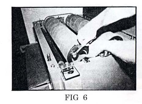
7 INSTALLING ABRASIVES B DUAL DRUM SANDER ASSEMBLY cont CAUTION: Disconnect the machine from the power source for installation or removal of abrasive paper. To install the abrasive paper, remove the four eye bolts and raise the drum cover. Remove the old paper by removing the Allen bolt #30 and the wedge #29 on the right of the drum. Remove the balance of the paper working your way to the left side. The left side is under spring pressure. When you have to come to the left side of the drum, release the paper and hold the drum to release the spring pressure. Next, remove the Allen bolt and the wedge from the left side. Save the paper you just removed to use as a pattern to cut the new abrasive with. Using the information in FIG (1) or the piece that you saved use the following procedure. Cut a new abrasive to install into the machine. To start installation of the paper, remove the 2 Allen bolts #30 and the 2 wedges #29 from the drum Next, insert the paper in the end of the left drum and install the wedge #29 and the Allen bolt #30 as shown in FIG (2) Next, hold the drum and pull the paper towards the front of the machine to engage the spring tensioner as shown in FIG (3) Continue to hold pressure on the drum while wrapping the paper around the drum for 2 full wraps. Do not release the drum until the paper has had 2 full wraps around the drum or the spring tension will be released and you will have to start over again. Continue wrapping the drum and install the tapered end of the paper in the end of the drum and install the wedge #29 and the Allen bolt #30. See FIG 5 If the end of the paper does not align with the place for the wedge, loosen the drum collar bolt (#40. FIG 6) and rotate the drum collar #28 until it properly aligns with the paper. Then retighten the retainer bolt #40. 7


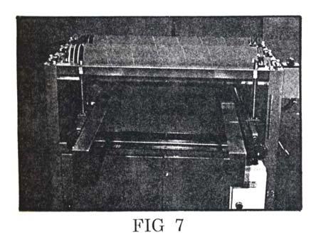
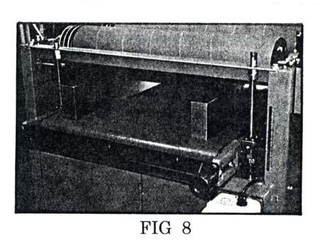
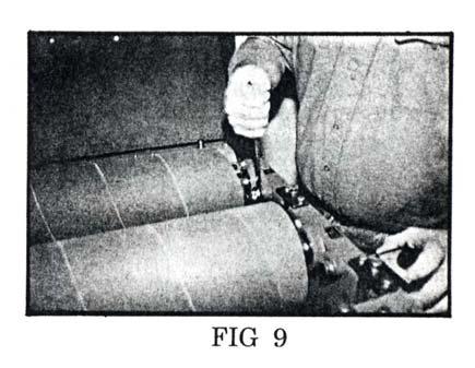
8 B DUAL DRUM SANDER ASSEMBLY cont FIG 1 ADJUSTING THE DRUM ROLLERS It may be necessary to periodically adjust the height of the drums and when using grits of different sizes, always install the coarser grit in the front drum. To adjust the drum after installing the abrasive, make the depth gauge as show in FIG 7 & 8. (Next Page) Raise the table until the front of the drum just contacts the gauge. If only a minor adjustment is necessary, you will adjust the drums. If a major adjustment is necessary, which is unlikely, you must adjust the table. To make a minor adjustment, loosen the bearing housing bolts #38 on both ends of the drum. FIG 9. Lower the drum until it just touches the gauge and re-tighten the bolts #38. 8


9 B DUAL DRUM SANDER ASSEMBLY cont 9
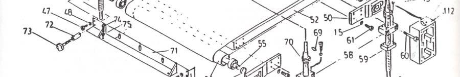
10 B DUAL DRUM SANDER WHEN RE-INSTALLING THE SAME GRIT ON BOTH DRUMS, YOU MUST RE- ADJUST THE DRUM HEIGHT. To make a major adjustment to the table requires the use of both depth gauges. Place the gauges under the drums near the outside edges of the table as shown in FIG 10. Raise the table until contact is made between the drums and the gauges. If both drums do not touch the gauges, the table must be adjusted. To adjust the tables, loosen the chain adjuster bolt #74 & remove the chain #88 from all 4 sprockets #64. FIG 11 Next, insert a screwdriver or similar tool in the hole in the top post #62, FIG 10. At the corner of the table that is lowest, turn clockwise to raise the table until the drum contacts the gauge. Do this for each post until even contact is made with the gauge. Re-install the chain #88 on all 4-corner posts and install the chain adjuster so that there is approx. 1/8 deflection in the chain between the front corner posts & the tensioner. Next, lower the table until the gauges can be removed. Now you must adjust each of the 3 hold down rollers. HOLD DOWN ROLLER ADJUSTMENT Hold down rollers will need adjustment if the material cannot be fed under the drums or when the finished surface is uneven. To adjust the rollers, loosen the roller pressure or raise the bolt to decrease the pressure. Do not over tighten the bolt as excessive down pressure will not allow material under the rollers or the conveyor belt can be stopped. MAINTANENCE About once a week, check the oil level in the gearbox. If the oil is visible in the eyeglass on the side of the gearbox, the oil is at the proper level. To add oil to the gearbox, remove the Allen bolt #136, spring #137 and ball #138. Remove the Allen bolt #86. Remove the shifter assembly and add the proper amount of machine oil. After, re-install the assembly with the shaft #134 between gears of #118. Install bolt #86 and the ball #138, spring #137 and set screw #136. The gearbox will operate at 11 FPM or 17 FPM in either direction. The gearbox speed can only be changed when the conveyor belt is moving. The conveyor belt on the sander can be used in both a forward & reverse direction. The drums rotate in only one direction. CAUTION: When changing the direction of the belt travel, allow the conveyor belt to completely stop before changing the direction of travel. 10

11 B DUAL DRUM SANDER ASSEMBLY cont DRIVE BELT ADJUSTMENT & REPLACEMENT Always replace the drive belts in matched sets of the proper size. The belt is properly adjusted if it will deflect ½ when pushed between the motor and drums. Also check that the belts ride in the center of the pulleys. Adjust the motor pulley as necessary. LUBRICATION There are grease fittings on the end of the drums that require periodic lubrication from a grease gun. The chain drive below the table also requires periodic lubrication and cleaning from build up of sawdust. At the end of each of the three hold down rollers is a bushing that should be lubricated with a dry type lubricant like graphite or silicone that will not attract build up. You now should be ready to make your first pass on your B2022. With proper maintenance, this drum sander should provide with years of Craft Excellence. 11
12 B DUAL DRUM SANDER WIRING DIAGRAM 12

13 13
14 14
15 15

16 16
17 17
18 18
19 19
20 20
21 21
22 22
23 WARRANTY CRAFTEX 2 YEAR LIMITED WARRANTY Craftex warrants every product to be free from defects in materials and agrees to correct such defects where applicable. This warranty covers two years for parts and 90 days for labour (unless specified otherwise), to the original purchaser from the date of purchase but does not apply to malfunctions arising directly or indirectly from misuse, abuse, improper installation or assembly, negligence, accidents, repairs or alterations or lack of maintenance. Proof of purchase is necessary. All warranty claims are subject to inspection of such products or part thereof and Craftex reserves the right to inspect any returned item before a refund or replacement may be issued. This warranty shall not apply to consumable products such as blades, bits, belts, cutters, chisels, punches etceteras. Craftex shall in no event be liable for injuries, accidental or otherwise, death to persons or damage to property or for incidental contingent, special or consequential damages arising from the use of our products. RETURNS, REPAIRS AND REPLACEMENTS To return, repair, or replace a Craftex product, you must visit the appropriate Busy Bee Tools showroom or call BUSY. Craftex is a brand of equipment that is exclusive to Busy Bee Tools. For replacement parts directly from Busy Bee Tools, for this machine, please call BUSY (2879), and have your credit card and part number handy. All returned merchandise will be subject to a minimum charge of 15% for re-stocking and handling with the following qualifications. Returns must be pre-authorized by us in writing. We do not accept collect shipments. Items returned for warranty purposes must be insured and shipped pre-paid to the nearest warehouse Returns must be accompanied with a copy of your original invoice as proof of purchase. Returns must be in an unused condition and shipped in their original packaging a letter explaining your reason for the return. Incurred shipping and handling charges are not refundable. Busy Bee will repair or replace the item at our discretion and subject to our inspection. Repaired or replaced items will be returned to you pre-paid by our choice of carriers. Busy Bee reserves the right to refuse reimbursement or repairs or replacement if a third party without our prior authorization has carried out repairs to the item. Repairs made by Busy Bee are warranted for 30 days on parts and labour. Any unforeseen repair charges will be reported to you for acceptance prior to making the repairs. The Busy Bee Parts & Service Departments are fully equipped to do repairs on all products purchased from us with the exception of some products that require the return to their authorized repair depots. A Busy Bee representative will provide you with the necessary information to have this done. For faster service it is advisable to contact the nearest Busy Bee location for parts availability prior to bringing your product in for repairs. 23
24 24
25 25
26 26
IMPORTANT READ ME FIRST
 IMPORTANT READ ME FIRST Thank you for purchasing your Kushlan Mixer. We hope that you will enjoy using it for many years to come. SHOULD YOU REQUIRE ANY SET-UP OR OPERATING ASSISTANCE WITH YOUR PRODUCT,
Kushlan Products, Inc. !IMPORTANT! Read Me First!
 Kushlan Products, Inc.!IMPORTANT! Read Me First! Thank you for purchasing this Kushlan Product. We hope you will enjoy using it for many years. Be sure to keep your box and all packing material in case
IMPORTANT READ ME FIRST
 IMPORTANT READ ME FIRST Thank you for purchasing your Kushlan Mixer. We hope that you will enjoy using it for many years to come. SHOULD YOU REQUIRE ANY SET-UP OR OPERATING ASSISTANCE WITH YOUR PRODUCT,
TABLE OF CONTENTS DESCRIPTION SAFETY
 TABLE OF CONTENTS Description... 1 Safety... 1-2 Purpose of this Manual...... 2 Important Safety Information......3 Identification.......3 Set-up and Operation.......4-9 Maintenance.....10 Specifications....10
CAMBELT TENSION GAUGE
 CAMBELT TENSION GAUGE Model 96557 Operating Instructions Diagrams within this manual may not be drawn proportionally. Due to continuing improvements, actual product may differ slightly from the product
FTFR Maintenance and Parts Manual SQ-1 FLOOR TRUSS FINISH ROLLER. Operators Manual
 FTFR Maintenance and Parts Manual SQ-1 FLOOR TRUSS FINISH ROLLER Operators Manual FOREWORD This manual explains the proper maintenance of Square 1 Design Floor Truss Finish Roller as well as the daily
OPERATING and MAINTENANCE INSTRUCTIONS MAX PUNCH TM T HYDRAULIC PUNCH (MP360SDPRO)
") OPERATING and MAINTENANCE INSTRUCTIONS MAX PUNCH TM 360 12T HYDRAULIC PUNCH (MP360SDPRO) 08/17 MP360SDPRO Manual READ AND UNDERSTAND ALL INSTRUCTIONS AND SAFETY INFORMATION IN THIS MANUAL BEFORE OPERATING
OPERATING and MAINTENANCE INSTRUCTIONS MAX PUNCH TM 360 12T HYDRAULIC PUNCH (MP360SDPRO) 08/17 MP360SDPRO Manual READ AND UNDERSTAND ALL INSTRUCTIONS AND SAFETY INFORMATION IN THIS MANUAL BEFORE OPERATING
SUBMERSIBLE PUMP. Model ASSEMBLY AND OPERATING INSTRUCTIONS
 SUBMERSIBLE PUMP Model 37952 ASSEMBLY AND OPERATING INSTRUCTIONS 3491 Mission Oaks Blvd., Camarillo, CA 93011 Visit our Web site at: http://www.harborfreight.com Copyright 2003 by Harbor Freight Tools.
accidents which arise due to nonobservance and the safety information herein. SPECIFICATIONS
 22 TON LOG SPLITTER Model: 6212 CALIFORNIA PROPOSITION 65 WARNING: You can create dust when you cut, sand, drill or grind materials such as wood, paint, metal, concrete, cement, or other masonry. This
1200W Paint DRYING Lamp
 1200W Paint DRYING Lamp Model 97641 Assembly And Operation Instructions Diagrams within this manual may not be drawn proportionally. Due to continuing improvements, actual product may differ slightly from
OPERATOR'S MANUAL W Series Premium Pallet Trucks
 OPERATOR'S MANUAL W Series Premium Pallet Trucks JET EQUIPMENT & TOOLS, INC. P.O. BOX 1349 253-351-6000 A WMH Company Auburn, WA 98071-1349 Fax 800-274-6840 www.jettools.com e-mail jet@jettools.com M-140075
Linear Actuator. Installation Manual. warranty installation parts list. Linear Actuator Installation Manual Page 1
 Linear Actuator Installation Manual warranty installation parts list January 2004 Linear Actuator Installation Manual Page 1 MA1221B12 Warranty Information Chore-Time Equipment ( Chore-Time ) warrants
INSTRUCTIONS FOR OUTDOOR WALL LANTERN, MODEL LPT-1032
 INSTRUCTIONS FOR OUTDOOR WALL LANTERN, MODEL LPT-1032 Page 1 Thank you for purchasing this Langport Lighting outdoor wall lantern. This product has been manufactured with the highest standards of safety
p.t.o. Slip clutch Read this material before using this product. Failure to do so can result in serious injury. Save this manual.
 p.t.o. Slip clutch 65517 Installation Instructions Distributed exclusively by Harbor Freight Tools. 3491 Mission Oaks Blvd., Camarillo, CA 93011 Visit our website at: http://www.harborfreight.com Read
1000-LB. MOTORCYCLE LIFT TABLE OWNER S MANUAL
 1000-LB. MOTORCYCLE LIFT TABLE OWNER S MANUAL WARNING: Read carefully and understand all ASSEMBLY AND OPERATION INSTRUCTIONS before operating. Failure to follow the safety rules and other basic safety
Owner s Manual & Safety Instructions
 Owner s Manual & Safety Instructions Save Save This This Manual Keep Keep this this manual manual for for the the safety safety warnings warnings and and precautions, assembly, assembly, operating, inspection,
Drum Deheader. Owner s Manual
 Drum Deheader Owner s Manual WARNING: Read carefully and understand all ASSEMBLY AND OPERATION INSTRUCTIONS before operating. Failure to follow the safety rules and other basic safety precautions may result
SIDE-WIND, A-FRAME TRAILER JACK. Model Due to continuing improvements, actual product may differ slightly from the product described herein.
 SIDE-WIND, A-FRAME TRAILER JACK Model 95157 Assembly And Operation Instructions Due to continuing improvements, actual product may differ slightly from the product described herein. 3491 Mission Oaks Blvd.,
OPERATING and MAINTENANCE INSTRUCTIONS MAXIS Grips
 OPERATING and MAINTENANCE INSTRUCTIONS MAXIS Grips (GP110/GP00AA/GP101A /GP102B/GP103C/GP104D) 04/17 GP110/GP00AA/GP101A/GP102B/GP103C/GP104D Manual READ AND UNDERSTAND ALL OF THE INSTRUCTIONS AND SAFETY
Swing Arm Magnifying Lamp
 Owner s Manual & Safety Instructions Save This Manual Keep this manual for the safety warnings and precautions, assembly, operating, inspection, maintenance and cleaning procedures. Write the product s
User Instruction Manual
 RAIL LOCK SPRING COMPRESSOR User Instruction Manual For Spring and Gas Piston Rifles and Pistols V1 03/16 Contents Parts of the Rail Lock compressor...3 Disassembling your rifle or pistol...4-6 Assembling
BCFS Belt Driven Centrifugal Filtered Supply Fans
 BCFS Belt Driven Centrifugal Filtered Supply Fans INSTALLATION, OPERATION & MAINTENANCE MANUAL IM-4300 August 2014 Throughout this manual, there are a number of HAZARD S that must be read and adhered to
Operating Instructions and Parts Manual PTX and JTX Series Pallet Trucks Models PTX-2036, PTX-2048, PTX-2748, and JTX-2748
 Operating Instructions and Parts Manual PTX and JTX Series Pallet Trucks Models PTX-2036, PTX-2048, PTX-2748, and JTX-2748 For models with serial no. 11xx0001 and higher WALTER MEIER (Manufacturing) Inc.
VIBRATORY SCREED OPERATOR/PARTS MANUAL
 VIBRATORY SCREED OPERATOR/PARTS MANUAL PO Box 3147 Rock Hill, SC 29732 USA Phone 803-324-3011 Toll Free 800-433-3026 Parts Department Fax 800-633-5534 TABLE OF CONTENTS Specifications Page 1 Engine Assembly
1250 LB. CAPACITY MECHANICAL WHEEL DOLLY
 1250 LB. CAPACITY MECHANICAL WHEEL DOLLY 67287 SET-UP AND OPERATING INSTRUCTIONS Visit our website at: http://www.harborfreight.com Read this material before using this product. Failure to do so can result
accidents which arise due to nonobservance and the safety information herein.
 2000LB WINCH Model: 7247 CALIFORNIA PROPOSITION 65 WARNING: You can create dust when you cut, sand, drill or grind materials such as wood, paint, metal, concrete, cement, or other masonry. This dust often
Manual Operated Floor Jack
 Manual Operated Floor Jack OPERATING INSTRUCTIONS Note: There may be some slight differences in the appearance of the various manually-operated floor jacks, however the instructions in this manual apply
18 GAUGE FLOORING STAPLER. Models: /13
 18 GAUGE FLOORING STAPLER Models: 7560 CALIFORNIA PROPOSITION 65 WARNING: You can create dust when you cut, sand, drill or grind materials such as wood, paint, metal, concrete, cement, or other masonry.
Owner s Manual, Operating Instructions Manual, and Replacement Parts Manual. Lift-Rite Titan Series Hand Pallet Trucks Model LCF55 - Freezer Special
 Owner s Manual, Operating Instructions Manual, and Replacement Parts Manual Lift-Rite Titan Series Hand Pallet Trucks Model LCF55 - Freezer Special Lift-Rite, 5975 Falbourne Street, Mississauga, Ontario
TIRE GROOVER OPERATING INSTRUCTIONS UPRIGHT GROOVER
 TIRE GROOVER OPERATING INSTRUCTIONS UPRIGHT GROOVER SG MODEL READ INSTRUCTIONS THOROUGHLY BEFORE OPERATING 3451 S. 40th Street Phoenix, AZ 85040 602.437.5020 800.223.4540 www.tssissg.com info@tsissg.com
OWNER'S MANUAL GPW Series
 OWNER'S MANUAL GPW Series JET EQUIPMENT & TOOLS, INC. P.O. BOX 1349 Phone: 253-351-6000 A WMH Company Auburn, WA 98071-1349 Fax: 1-800-274-6840 www.jettools.com e-mail jet@jettools.com M-181000 06/01 This
Operating Instructions and Parts Manual Wide Belt Sanders
 Operating Instructions and Parts Manual Wide Belt Sanders Models RB-25 and RB-37 WMH TOOL GROUP 2420 Vantage Drive Elgin, Illinois 60123 Part No. M-0460181 Ph.: 800-274-6848 Revision E 4/04 www.wmhtoolgroup.com
Operating Instructions and Parts Manual AHR-50 Auto Rewind Hose Reel
 Operating Instructions and Parts Manual AHR-50 Auto Rewind Hose Reel JET 427 New Sanford Road LaVergne, Tennessee 37086 Part No. M-426238 Ph.: 800-274-6848 Revision C 04/2017 www.jettools.com Copyright
Water Broom. Instruction manual ESPAÑOL: PÁGINA 7 FRANÇAIS : PAGE 13 MODEL PCA270
 ESPAÑOL: PÁGINA 7 FRANÇAIS : PAGE 13 Instruction manual Water Broom MODEL PCA270 To learn more about Porter-Cable visit our website at: http://www.porter-cable.com IMPORTANT Please make certain that the
Heavy Duty Four Wheeled Walker
 Heavy Duty Four Wheeled Walker Weight Capacity: 500 lbs. ITEM # W1802 Made in China 2011 ESSENTIAL MEDICAL SUPPLY, INC. Manufactured for Orlando, FL 32822 -- SAVE THESE INSTRUCTIONS -- Do not attempt to
SPECIFICATIONS GENERAL SAFETY RULES PERSONAL SAFETY. Save This Manual TOOL USE AND CARE WORK AREA
 SPECIFICATIONS 2 Forged Safety Latch Hooks Cable extends to: 44 Drop forged steel hanging bracket Heavy duty 3/16 Steel Cable Pulling Capacity: 1200 LB. One piece double ratchet gear Save This Manual You
4400-Lb. Capacity Extra-Long Pallet Jack
 4400-Lb. Capacity Extra-Long Pallet Jack Owner s Manual WARNING: Read carefully and understand all ASSEMBLY AND OPERATION INSTRUCTIONS before operating. Failure to follow the safety rules and other basic
INSTRUCTIONS FOR OUTDOOR WALL LANTERN, MODEL LPT-1107
 INSTRUCTIONS FOR OUTDOOR WALL LANTERN, MODEL LPT-1107 Page 1 Thank you for purchasing this Langport Lighting outdoor wall lantern. This product has been manufactured with the highest standards of safety
Table of Contents. Safety... 2 Specifications... 3 Setup Parts List and Diagram Warranty Operation Maintenance
 Table of Contents Safety Setup Operation Maintenance Safety... 2 Specifications... 3 Setup... 4 Operation... 5 WARNING SYMBOLS AND DEFINITIONS Maintenance... 9 Parts List and Diagram... 10 Warranty...
Model 35 PARTS MANUAL
 Model 35 PARTS MANUAL Version 3-2007 Ashland Industries Inc. 1115 Rail Drive P.O. Box 717 Ashland, WI. 54806 Ph: 877-634-4622 Toll Free Ph: 715-682-4622 Fx: 715-682-9717 www.ashlandind.com Model 35 Scraper
Installation / Operation Instructions Sunnex ORION Series Exam Lights
 Installation / Operation Instructions Sunnex ORION Series Exam Lights OR-120 OR-127 OR-220 OR-227 Models: OR-300 OR-400 OR-500 OR-600 1. APPLICATIONS The Sunnex ORION Series light was designed specifically
Operating Instructions and Parts Manual Hydraulic Pipe Bender Models: JHPB-20 (2-inch), JHPB-30 (3-inch)
, JHPB-30 (3-inch)") Operating Instructions and Parts Manual Hydraulic Pipe Bender Models: JHPB-20 (2-inch), JHPB-30 (3-inch) JET 427 New Sanford Road LaVergne, Tennessee 37086 Part No. M-331900 Ph.: 800-274-6848 Revision
Operating Instructions and Parts Manual Hydraulic Pipe Bender Models: JHPB-20 (2-inch), JHPB-30 (3-inch) JET 427 New Sanford Road LaVergne, Tennessee 37086 Part No. M-331900 Ph.: 800-274-6848 Revision
Mini Lever Hoist. Owner s Manual
 Mini Lever Hoist Owner s Manual WARNING: Read carefully and understand all ASSEMBLY AND OPERATION INSTRUCTIONS before operating. Failure to follow the safety rules and other basic safety precautions may
HA/HAB Fiberglass Wall Mount Ventilators
 HA/HAB Fiberglass Wall Mount Ventilators INSTALLATION, OPERATION & MAINTENANCE MANUAL IM-3100 August 2015 Throughout this manual, there are a number of HAZARD S that must be read and adhered to in order
Champion Chippers OPERATOR S MANUAL. Operation & Safety. Includes Model: CX850 CX851. Part #
 OPERATOR S MANUAL Champion Chippers Operation & Safety Includes Model: CX850 CX851 Part # 990026 YOU MUST FILL OUT YOUR WARRANTY REGISTRATION TO ACTIVATE YOUR WARRANTY AND TO QUALIFY FOR PARTS SERVICE!!
Please read and understand instructions before attempting installation. HDHWF (e/h)
") HDHWF (e/h) Universal Manual Fire Door Hoist e standard hoist h heavy duty hoist Contents: Introduction Page 2 Installation Page 3 Mounting the unit Page 3 Release arm disengaged position Page 4 Release
HDHWF (e/h) Universal Manual Fire Door Hoist e standard hoist h heavy duty hoist Contents: Introduction Page 2 Installation Page 3 Mounting the unit Page 3 Release arm disengaged position Page 4 Release
Important Operating Instructions and Warranty Information On Your New Electronic AMSEC Safe
 Important Operating Instructions and Warranty Information On Your New Electronic AMSEC Safe MODELS: ES914, ES149, ES1814, ES813, ES916, ES1014, ES2014, ES412, WES149, WES2114 Read Contents Carefully For
Read this entire manual before operation begins.
 Read this entire manual before operation begins. Record below the following information which is located on the serial number data plate. Serial No. Model No. Date of Installation Contents Specifications.............
MBF-P 2040 PLASTIC MODULAR BELT CONVEYOR
 Technical Documentation PLASTIC MODULAR BELT CONVEYOR Each serial number is unique to that specific conveyor and provides mk North America with complete order details. The conveyor serial number is located
OPERATOR S MANUAL with Parts List & Warranty. For Model 100SP Topdresser
 OPERATOR S MANUAL with Parts List & Warranty For Model 100SP Topdresser July 30, 2009 Model 100SP Topdresser LIMITED WARRANTY Earth & Turf Products, LLC warrants to the original Purchaser, all Earth &
Manual Chain Hoist. Owner s Manual
 Manual Chain Hoist Owner s Manual WARNING: Read carefully and understand all ASSEMBLY AND OPERATION INSTRUCTIONS before operating. Failure to follow the safety rules and other basic safety precautions
Vertical Stacking System for both Floor and Roof Lines. SQ-1 INTELLIGENT STACKERS. Operators Manual
 Vertical Stacking System for both Floor and Roof Lines. SQ-1 INTELLIGENT STACKERS Operators Manual FOREWORD This manual explains the proper maintenance of Square 1 Design Intelligent Stacking System as
RolsplicerTM. Maintenance Manual And Illustrated Parts List
 RolsplicerTM Maintenance Manual And Illustrated Parts List List of Illustrations Figure Page. Rolsplicer 3 2. Roller Adjustment 4 3. Rolsplicer 6 4. Lid Hold Down Assembly 8 5. Automatic Lid Speed Adjustment
DISC BRAKE CALIPER TOOL SET
 DISC BRAKE CALIPER TOOL SET 40732 ASSEMBLY AND OPERATING INSTRUCTIONS Diagrams within this manual may not be drawn proportionally. Due to continuing improvements, actual product may differ slightly from
151 Border Machine OPERATING INSTRUCTIONS MAINTENANCE INSTRUCTIONS ILLUSTRATED PARTS LIST
 Terrco, Inc. 151 Border Machine OPERATING INSTRUCTIONS MAINTENANCE INSTRUCTIONS ILLUSTRATED PARTS LIST Terrco, Inc. 222 1st Avenue NW Watertown, SD 57201 Phone: (605) 882-3888 Fax: (605) 882-0778 Email:
Hydraulic Furniture Movers
 Hydraulic Furniture Movers Owner s Manual WARNING: Read carefully and understand all ASSEMBLY AND OPERATION INSTRUCTIONS before operating. Failure to follow the safety rules and other basic safety precautions
SUBMERSIBLE MINI-PUMP
 SUBMERSIBLE MINI-PUMP Model 41287 Set up And Operating Instructions Diagrams within this manual may not be drawn proportionally. Due to continuing improvements, actual product may differ slightly from
Operating Instruction and. Parts Manual for
 Operating Instruction and 000DD Parts Manual for WARNING DO NOT ATTEMPT TO START OR OPERATE THE MACHINE UNTIL ALL THE INSTRUCTIONS HAVE BEEN READ AND UNDERSTOOD BY THE OPERATOR. FAILURE TO DO SO COULD
Owner s Manual, Operating Instructions Manual, and Replacement Parts Manual
 Owner s Manual, Operating Instructions Manual, and Replacement Parts Manual Lift-Rite Titan Series Hand Pallet Trucks Models LCR55 and LCS55 Versions This publication, 1130442C, applies to the Lift-Rite
KLAISLER MANUFACTURING CORPORATION
 KLAISLER MANUFACTURING CORPORATION FINISH ROLLER MANUAL MODELS: TR210-24 TR214-24 TR216-24 TR212-24 TR215-24 VOLUME 1, EDITION 4 7/15/04 FOREWORD This manual explains the proper maintenance of Klaisler
STRAIGHT DIE GRINDER MODEL EGA530 OWNERS MANUAL
 STRAIGHT DIE GRINDER MODEL EGA530 OWNERS MANUAL www.eaglecompressor.com 1-800-551-2406 READ THE ENTIRE MANUAL BEFORE PUTTING THIS TOOL IN SERVICE Limited Air Tool Warranty Eagle warrants air tools of its
Part Number Mini Linear Lift Assembly Installation & Operator s Instruction Manual
 Part Number 39644 Mini Linear Lift Assembly Installation & Operator s Instruction Manual April 1999 MV1505C Chore-Time Warranty Mini Linear Lift Assembly Manual Chore-Time Warranty Chore-Time Equipment
Electro-Brake 375, 475, 650, 825, 1000, 1225
 Electro-Brake 375, 475, 650, 825, 1000, 1225 P-211-WE 819-0043 Installation Instructions An Altra Industrial Motion Company Contents Installation Instructions.... 2 Electrical Coil Data.... 5 Burnishing
INSTALLATION TURN SIGNAL MIRRORS 1432
 1432 PARTS INCLUDED 1 Left Side Turn Signal Mirror Assembly with Convex Glass 1 Right Side Turn Signal Mirror Assembly with Convex Glass 1 Hardware Kit, Including: 2 5/16-18 X 1-1/2 Socket Head Cap Screws
MAXILATOR OPERATOR'S MANUAL INLINE MOWER CADDY MODEL MBS RICE ROAD ROCKMART, GA (866) HAYBALE
 HAYBALE") MAXILATOR OPERATOR'S MANUAL INLINE MOWER CADDY MODEL MBS-80 51 RICE ROAD ROCKMART, GA 30153 (866) HAYBALE MAXILATOR EQUIPMENT, LLC Phone: (866) HAYBALE LIMITED WARRANTY Effective January 1, 2016 Maxilator
MAXILATOR OPERATOR'S MANUAL INLINE MOWER CADDY MODEL MBS-80 51 RICE ROAD ROCKMART, GA 30153 (866) HAYBALE MAXILATOR EQUIPMENT, LLC Phone: (866) HAYBALE LIMITED WARRANTY Effective January 1, 2016 Maxilator
Instruction Sheet SRSR SERIES. Rotating Sliding Rail System
 Instruction Sheet SRSR SERIES Rotating Sliding Rail System THANK YOU Thank you for purchasing the SRSR Series Rotating Sliding Rail System. Please read these instructions thoroughly before assembling this
Junior Sandblaster. Model #51 WARNING! FOR YOUR SAFETY PLEASE READ INSTRUCTIONS BEFORE OPERATING TOOL & WEAR EYE PROTECTION
 Junior Sandblaster Model #51 WARNING! FOR YOUR SAFETY PLEASE READ INSTRUCTIONS BEFORE OPERATING TOOL & WEAR EYE PROTECTION PARTS LIST AND PART NUMBERS 01.Red Rubber Air Hose (5Ft) P51-01 02. Male Insert
MODEL EGA220 OWNERS MANUAL
 1/4 MINI RATCHET MODEL EGA220 OWNERS MANUAL www.eaglecompressor.com 1-800-551-2406 READ THE ENTIRE MANUAL BEFORE PUTTING THIS TOOL IN SERVICE Limited Air Tool Warranty Wood Industries, Inc. warrants air
SPECIFICATIONS CONTENTS:
 Model 3052 1,100 Lbs 2 Stage Transmission Jack INSTRUCTION MANUAL CONTENTS: Page 1 Specifications Page 2 Warning Information Page 3 Assembly Page 4 Operating Instructions Page 4 Preventative Maintenance
SLAB SAW SERIES PARTS LIST
 SLAB SAW SERIES PARTS LIST MODELS: HP Part# 020 HP20 Part# 02020 HP2 Part# 0202 MADE IN USA MADE IN USA Revision 09.20 Manual Part No. 6269 Caution: Read all safety and operating instructions before using
CONTENTS: SPECIFICATIONS 5712BT - 12 TON BENCH TOP HYDRAULIC SHOP PRESS OWNER'S MANUAL
 OWNER'S MANUAL CONTENTS: Page 1 Specifications 2 Warning Information 3 Assembly and Operating Instructions 4 Preventative Maintenance and Warranty Information 5 Exploded View Drawing and Parts List SPECIFICATIONS
Mini Cement Mixer. Owner s Manual
 Mini Cement Mixer Owner s Manual WARNING: Read and understand all instructions, warnings, and cautions before using this product. Failure to follow the instructions, warnings, and cautions may result in
3.5 CUbIC feet portable CEMENT MIxER 02/2015 INSTRUCTION MANUAL MODEL: KC-15CM-2 COPYRIGHT 2014 ALL RIGHTS RESERVED BY KING CANADA TOOLS INC.
 3.5 CUbIC feet portable CEMENT MIxER 02/2015 MODEL: KC-15CM-2 INSTRUCTION MANUAL COPYRIGHT 2014 ALL RIGHTS RESERVED BY KING CANADA TOOLS INC. WARRANTY INfORMATION 2-YEAR LIMITED WARRANTY FOR THIS CEMENT
IMPORTANT SAFETY INFORMATION
 Specifications Overall Dimensions Batteries 9" L x 6-3/4" W x 6-3/4" H 4 - AA (sold separately) IMPORTANT SAFETY INFORMATION Installation Precautions 1. Verify that installation surface has no hidden utility
MINI AIR ANGLE DIE GRINDER
 MINI AIR ANGLE DIE GRINDER Model 33171 ASSEMBLY AND OPERATING INSTRUCTIONS Due to continuing improvements, actual product may differ slightly from the product described herein. 3491 Mission Oaks Blvd.,
SPECIFICATIONS CONTENTS: Specifications Warning Information. Operating Instructions Preventative Maintenance Troubleshooting
 Model 3182 2,500 Lbs Power Train Table/Lift OWNER'S MANUAL CONTENTS: Page 1 Page 2-3 Page 3 Page 4 Page 5 Page 5 Page 6 Page 7 Page 8 Specifications Warning Information Setup Operating Instructions Preventative
Auto-Locking Trailer Coupler
 Auto-Locking Trailer Coupler 7-Ton Capacity Owner s Manual WARNING: Read carefully and understand all ASSEMBLY AND OPERATION INSTRUCTIONS before operating. Failure to follow the safety rules and other
MODEL EGA200 OWNERS MANUAL
 3/8 RATCHET WRENCH MODEL EGA200 OWNERS MANUAL www.eaglecompressor.com 1-800-551-2406 READ THE ENTIRE MANUAL BEFORE PUTTING THIS TOOL IN SERVICE Limited Air Tool Warranty Wood Industries, Inc. warrants
Operating Instructions and Parts Manual 3-1/2 ton Farm Jack Model FJ-3-1/2A
 Operating Instructions and Parts Manual 3-1/2 ton Farm Jack Model FJ-3-1/2A JET 427 New Sanford Road LaVergne, Tennessee 37086 Part No. M-440436 Ph.: 800-274-6848 Revision A1 06/2014 www.jettools.com Copyright
Use/Installation Guide
 Use/Installation Guide 5 Series Outdoor Gas Grill Carts IMPORTANT: PLEASE READ AND FOLLOW 1. Before beginning, please read these instructions completely and carefully. 2. Do not remove permanently affixed
Raydot LLC 24 Actuator (115 VOLT)
") Installation, Operation & Parts Manual Read carefully the information provided. Retain manual for future reference. Raydot LLC 24 Actuator (115 VOLT) 145 Jackson Ave. S. Cokato, MN 55321-USA (320) 286-2103
Installation, Operation & Parts Manual Read carefully the information provided. Retain manual for future reference. Raydot LLC 24 Actuator (115 VOLT) 145 Jackson Ave. S. Cokato, MN 55321-USA (320) 286-2103
O P E R A T O R S M A N U A L
 B Y T U R F M A S T E R I N D U S T R I E S O P E R A T O R S M A N U A L HM-1548 Turfmaster Industries Operator s Manual 1 INTRODUCTION The Sweep-All attachment clears and collects materials including
READ AND SAVE THESE INSTRUCTIONS. Centrifugal Downblast Exhaust Fan Belt Driven for Roof & Wall Mounting
 READ AND SAVE THESE INSTRUCTIONS INSTALLATION, OPERATING INSTRUCTIONS & PARTS MANUAL Centrifugal Downblast Exhaust Fan Belt Driven for Roof & Wall Mounting Electrical wiring and connections should be done
GUF-P MINI BELT CONVEYOR
 Technical Documentation GUF-P MINI BELT CONVEYOR Each serial number is unique to that specific conveyor and provides mk North America with complete order details. The conveyor serial number is located
4400-Lb. Capacity Pallet Jack
 Read carefully and understand all ASSEMBLY AND OPERATION INSTRUCTIONS before operating. Failure to follow the safety rules and other basic safety precautions may result in serious personal injury. Item#
INSTALLATION GUIDE. Tenino Retro Pot Filler Hi-Rise Kitchen Faucet PB-K05
 INSTALLATION GUIDE Tenino Retro Pot Filler Hi-Rise Kitchen Faucet PB-K05 RECOMMENDED TOOLS AND MATERIALS Sink Hole Cover (Optional) Allen Wrench Set Plumbers Putty Adjustable Wrench Tape Measure Basin
Operator s Manual. Nitro 1000 Nitro 1000X. Nitro 750 Nitro 750X. September REV0
 Operator s Manual Nitro 750 Nitro 750X Nitro 1000 Nitro 1000X September.27.2018REV0 Table of Contents Introduction...3 Safety.....4 Equipment Requirements......5 What You Have Received. 5 Serial Number...6
UNION Series No. 5 and No. 15 Roller Coater OPERATING MANUAL INDEX
 UNION Series No. 5 and No. 15 Roller Coater DATE: SERIAL NO.: OPERATING MANUAL INDEX Assembly Drawing No. Electrical Drawing No. Pneumatic Drawing No. A. INTRODUCTION Page 2 B. INSTALLATION Location Page
Prime Attachments & Custom Fab Brush Mower Owners/Operators Manual
 Prime Attachments & Custom Fab Brush Mower Owners/Operators Manual The operator is responsible for the safe operation and maintenance of the machine. It is important that anyone who uses the machine is
Sawhorse with Chainsaw Holder
 Sawhorse with Chainsaw Holder Owner s Manual Chainsaw not included. WARNING: Read carefully and understand all ASSEMBLY AND OPERATION INSTRUCTIONS before operating. Failure to follow the safety rules and
Read this entire manual before operation begins.
 Read this entire manual before operation begins. Record below the following information which is located on the serial number data plate. Serial No. Model No. Date of Installation Contents Specifications.............
WARRANTY POLICY FOR LD SERIES LABEL DISPENSERS REPAIR POLICY
 TDA025B INTRODUCTION Thank you for buying our automatic tape dispenser. The TDA025 can automatically cut and dispense many types of tape. Before using, please read this instruction manual carefully. WARRANTY
Toshin-Cho Itabashi-ku Tokyo, Japan Tel Fax /06
 4270 Airborn Drive Addison, TX 75001, USA Toll Free 800.259.1986 Tel 972.248.1999 Fax 972.248.1991 info@startinternational.com www.startinternational.com 1-26-14 Toshin-Cho Itabashi-ku Tokyo, Japan Tel
Operating Instructions and Parts Manual PTJ Series Pallet Trucks
 Operating Instructions and Parts Manual PTJ Series Pallet Trucks JET 427 New Sanford Road LaVergne, Tennessee 37086 Part No. M-151003 Ph.: 800-274-6848 Revision C1 09/2018 www.jettools.com Copyright 2017
PUSH BUTTON KEY CABINET
 PUSH BUTTON KEY CABINET Model 95689 INSTALLATION And Operation Instructions Due to continuing improvements, actual product may differ slightly from the product described herein. 3491 Mission Oaks Blvd.,
Part# ZX WD/4WD PRO RUNNER SS Lift PRO COMP SUSPENSION. Suspension Systems that Work!
 2360 Boswell Road Chula Vista, CA 91914 Phone 619.216.1444 Fax 619.216.1474 E-Mail tech@explorerprocomp.com PRO COMP SUSPENSION Suspension Systems that Work! Part# 1999-2006 Toyota Tundra 2WD/4WD PRO RUNNER
Operating Instructions and Parts Manual SLT-330F Scissor Lift Table
 Operating Instructions and Parts Manual SLT-330F Scissor Lift Table For serial no. 17020001 and higher JET 427 New Sanford Road LaVergne, Tennessee 37086 Part No. M-140771 Ph.: 800-274-6848 Revision C
MAXILATOR OPERATOR'S MANUAL INLINE MOWER CADDY MODEL MBS RICE ROAD ROCKMART, GA (866) HAYBALE
 HAYBALE") MAXILATOR OPERATOR'S MANUAL INLINE MOWER CADDY MODEL MBS-80 51 RICE ROAD ROCKMART, GA 30153 (866) HAYBALE MAXILATOR EQUIPMENT, LLC Phone: (866) HAYBALE LIMITED WARRANTY Effective January 1, 2016 Maxilator
MAXILATOR OPERATOR'S MANUAL INLINE MOWER CADDY MODEL MBS-80 51 RICE ROAD ROCKMART, GA 30153 (866) HAYBALE MAXILATOR EQUIPMENT, LLC Phone: (866) HAYBALE LIMITED WARRANTY Effective January 1, 2016 Maxilator
Parts Manual for 1000DD
 Operating Instruction and Parts Manual Instrucciones de operación y manual de partes de los modelos d instructions d utilisation et de pièces pour le modèle 1000DD Parts Manual for WARNING DO NOT ATTEMPT
Electric Chainsaw Sharpener With Bar Mount
 Electric Chainsaw Sharpener With Bar Mount Owner s Manual WARNING: Read carefully and understand all ASSEMBLY AND OPERATION INSTRUCTIONS before operating. Failure to follow the safety rules and other basic