Kollmorgen Direct Drive Linear Motor Selection Guide. with AKD TM Servo Drive Systems
|
|
|
- Melina Patrick
- 5 years ago
- Views:
Transcription


1 Kollmorgen Direct Drive Linear Motor Selection Guide with AKD TM Servo Drive Systems
2 Kollmorgen. Every solution comes from a real understanding of OEM challenges facing machine designers and users. The ever-escalating demands of the marketplace mean increased pressure on machine designers and users at every turn. Time constraints. Demands for better performance. Having to think about the next-generation machine even before the current one is built. While expectations are enormous, budgets are not. Kollmorgen s innovative motion solutions and broad range of quality products help engineers not only overcome these challenges but also build truly differentiated machines. Because motion matters, it s our focus. Motion can distinctly differentiate a machine and deliver a marketplace advantage by improving its performance. This translates to overall increased efficiency for your application. Perfectly deployed machine motion can make your customer s machine more reliable and efficient, enhance accuracy and improve operator safety. Motion also represents endless possibilities for innovation. We ve always understood this potential, and thus have kept motion at our core, relentlessly developing products that offer precision control of speed, accuracy and position in machines that rely on complex motion. 2 K O L KL OM LO L R MG OE RN G E N
3 KOLLMORGEN DIRECT DRIVE LINEAR MOTOR SELECTION GUIDE Removing the Barriers of Design, Sourcing, and Time At Kollmorgen, we know that OEM engineers can achieve a lot more when obstacles aren t in the way. So, we knock them down in three important ways: Integrating Standard and Custom Products The optimal solution is often not clear-cut. Our application expertise allows us to modify standard products or develop totally custom solutions across our whole product portfolio so that designs can take flight. Providing Motion Solutions, Not Just Components As companies reduce their supplier base and have less engineering manpower, they need a total system supplier with a wide range of integrated solutions. Kollmorgen is in full response mode with complete solutions that combine programming software, engineering services and best-in-class motion components. Global Footprint With direct sales, engineering support, manufacturing facilities, and distributors across North America, Europe, Middle East, and Asia, we re close to OEMs worldwide. Our proximity helps speed delivery and lend support where and when they re needed. Financial and Operational Stability Kollmorgen is part of Danaher Corporation, our $13B parent company. A key driver in the growth of all Danaher divisions is the Danaher Business System, which relies on the principle of kaizen or continuous improvement. Using world-class tools, cross-disciplinary teams of exceptional people evaluate processes and develop plans that result in superior performance. Table of Contents u Direct Drive Linear (DDL) Motor 4 u AKD Servo Drive 10 u Co-Engineering Capabilities 14 u Direct Drive Linear Motor Summary 15 u DDL Ironless - Non-cooled Data and Dimensions IL06 Series 18 IL12 Series 20 IL18 Series 22 IL24 Series 26 u Ironless Magnet Ways 28 u DDL Ironcore Data and Dimensions ICD05 Series 32 ICD10 Series 34 u ICD Magnet Ways 36 u DDL Ironcore - Non-cooled Data and Dimensions IC11 Series 40 IC22 Series 42 IC33 Series 46 IC44 Series 50 u DDL Ironcore - Water-cooled Data and Dimensions IC11 Series 54 IC22 Series 56 IC33 Series 60 IC44 Series 64 u Ironcore Magnet Ways 68 u Wiring and Output 70 u High Flex Cable Sets 72 u Application Sizing 74 u Model Nomenclature 78 u Motioneering Application Engine
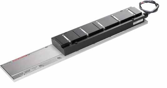
4 AD KI RD E CS T E RD VR O I VD E R ILV I EN E A R M O T O R Direct Drive Linear Motor Our direct drive linear motor series provide new dimension in performance with high throughput, accuracy, and zero maintenance. The product line are frameless, permanent magnet, three phase, brushless servomotors. The product line consists of two fundamental constructions, Ironless (slotless) and Ironcore. Ironless motors have no attractive force between the framless components and zero cogging for the ultra smooth motion. Ironcore motors provide the highest force per frame size. The feature a patented anti-cogging design which yields extremely smooth operation. 4 K O LK LOML OL RM GOERN G E N
5 The Benefits of Direct Drive Linear Motor Zero Maintenance with Greater Accuracy and Higher Bandwidth Wide Range of Sizes and Force to Cover any Linear Application Simplified, High Force Permanent Magnet Design Smoother velocity and reduced audible noise Power transmission without backlash Transmission elements such as couplings, toothed belts, ball/lead screws, rack & pinions, and other fitted components can be eliminated No gears or screws, no lubrication required Improved machine reliability Increased performance for the entire system Flat, compact drive solution Easily mix / match motors and drives Real-life acceleration up to 10 G Higher bandwidth and faster response than ball/lead screws or rack & pinion solutions Rapid indexing of heavy loads with peak force up to 12,500 N (2,800 lb) Reduced audible noise, fewer parts and lower cost of ownership More compact machine design D I R E C T D R I V E L I N E A R M O T O R 5
6 Direct Drive Linear Motor Overview D I R E C T D R I V E L I N E A R M O T O R O V E R V I E W Kollmorgen Direct Drive Linear DDL Motor Series Kollmorgen supplied its first linear motors in the late 1970 s for use in precision X-Y tables and coating systems. These were brush DC motors using the Kollmorgen patented push-through commutator bar method. This led to development in the early 1980 s of the brushless versions of the linear motor which were used in film processing applications where smooth, high stiffness, linear motion was required. During the past 30 years, advances in permanent magnet material, power semiconductors, and microprocessor technology have been the enablers for increased performance and lower costs for linear motors. DDL motors series comply with the Low Voltage Directive 73/23/EEC for installation in a machine. Safety depends upon installing and configuring motor per the manufacturer s recommendations. The machine in which this product is to be installed must conform to the provisions of EC directive 89/336/EEC. The installer is responsible for ensuring that the end product complies with all the relevant laws in the country where the equipment is installed. Standard Product Features Ironless: Peak force 60 to 1600 N (13.6 to 360 lbf) Continuous force 21 to 450 N (4.6 to 101lbf) Zero cogging Zero attractive force Smooth motion for speed as low as 1 micron/second ( in/sec) Low mass coil assembly for high acceleration Ironcore: Peak force IC series: 320 to 8407 N (71.9 to 1890 lbf) Continuous force IC series: 144 to 6916 N (32.4 to 1555 lbf) Peak force ICD series: 165 to 1099 N (38 to 254 lbf) Continuous force ICD series: 57.0 to 315 N (12.8 to 70.8 lbf) Patented anti-cogging technique for minimal cogging without magnet skewing High motor constant (Km) High force density ICD series advantage: Very low profile Low attraction force Suitable to replace many Ironless applications All Motors: Zero contact, zero maintenance, brushless design 3 phase sinusoidal commutation Peak accelerations easily above 10 G High position accuracy and resolution Very low settling time Low thermal losses Modular magnet design Standard Options: Hall effect feedback Thermal protection Thermistor Thermostat (Ironcore) Supplemental air or water cooling (Ironcore) Cable options Magnet way covers for easy cleaning (Ironcore) FM approved, hazardous environment 6 K O L L M O R G E N

.")
7 Our Direct Dirve Linear (DDL) motor series are frameless permanent magnet, three phase brushless servomotors. Fundamentally, a linear motor is a rotary motor that is rolled out flat. Stator Direct Drive Linear Motor Series with AKD Servo Drive D I R E C T D R I V E L I N E A R M O T O R O V E R V I E W N S Windings Slider Air Gap Rotor Rotary Motor Permanent Magnets Linear Motor Base Rotary Motor Rolled Out Flat The two primary components of permanent magnet brushless rotary motors are the stator (primary coils) and the rotor (secondary or rotating magnets). In brushless linear motors the rotor is rolled out flat to become the magnet track (also called the magnet way). The primary coils of the rotary motor are rolled out flat to become the coil assembly (also sometimes called the slider). In most brushless linear motor applications it is typical for the magnet way to be stationary and the coil assembly to be in motion, because of the relative masses of the two components. But it is also perfectly acceptable and sometimes advantageous to reverse this arrangement. The basic electromagnetic operating principles are the same in either case and are identical to those of a rotary motor. 7

, and low cogging forces without the need for")


8 Direct Drive Linear Motor Overview D I R E C T D R I V E L I N E A R M O T O R O V E R V I E W Ironless Motor Ironcore Motor Direct Drive Linear Motor Options Two types of linear motors are available, Ironcore and Ironless. Each one provides characteristics and features that are optimal depending upon the application. Ironcore motors have coils wound on silicon steel laminations, to maximize the generated force, with a single sided magnet way. Using a patented electromagnetic design, DDL linear motors have the highest rated force per size, a high Km motor constant (equals low thermal losses), and low cogging forces without the need for skewing of the magnets. The high thrust forces possible with these motors make them ideal for accelerating and moving high masses, and maintaining stiffness during machining or process forces. Ironless motors have no iron, or slots for the coils to be wound on. Therefore, these motors have zero cogging, a very light mass, and absolutely no attractive forces between the coil assembly and the magnet way. These characteristics are ideal for applications requiring very low bearing friction, high acceleration of lighter loads, and for maximizing constant velocity, even at ultra low speeds. The modular magnet ways consists of a double row of magnets to maximize the generated thrust force and to providea flux return path for the magnetic circuit. Feedback Types All brushless motors require feedback for commutation. The conventional rotary motor typically utilizes a resolver mounted on the rear of the motor or Hall effect devices mounted integrally in the coil windings. For a linear motor, commutation feedback can also be accomplished with a variety of methods. Digital or linear Hall effect devices are available from Kollmorgen for the DDL motor series which allow the drive electronics to commutate the linear motors in a manner identical to rotary motors. For exceptionally smooth motion requirements, sinusoidal drive electronics such as the Kollmorgen's AKD series, using digital Hall effects, provide sinusoidal drive currents to the motor for the best constant force and velocity performance. As an alternative, it is typical for linear motor applications to have a linear encoder present in the system for position feedback. It is increasingly common today for drive amplifiers, such as the AKD Digital amplifier, to derive the necessary commutation information directly from this linear encoder, either with or without supplemental digital Hall effect devices on startup. Other types of feedback used on linear motor applications include linear Inductosyns, laser interferometers, and LVDT. 8 K O L L M O R G E N
9 Advantages Wide Speed Range Since the frameless parts of the linear motor are non-contact, and no limitations of a mechanical transmission are present, both very high speeds and very low speeds are easily obtainable. Speeds are truly not limited by the motor. Instead, by eliminating the mechanical transmission, speed becomes limited by other elements in the system such as the linear bearings, and the achievable bandwidth from any feedback devices. Application speeds of greater than 5 meters per second (200 in./sec.) or less than 1 micron per second ( in./sec.) are typically achievable. In comparison, mechanical transmissions such as ball screws are commonly limited to linear speeds of 0.5 to 0.7 meters per second (20-30 in./sec.) because of resonances and wear. In addition to a wide speed range, linear motors, both ironcore and ironless, have excellent constant velocity characteristics, typically better than ± 0.01% speed variation. High System Dynamics In addition to high speed capability, direct drive linear motors are capable of very high accelerations. Limited only by the system bearings, accelerations of 3 to 5 G are quite typical for the larger motors and accelerations exceeding 10 G are easily achievable for smaller motors. Easy Selection process: 1. Determine peak and continuous force required for your applications (see our applications section on pages or use MOTIONEERING, our online sizing and selection software tool) 2. Use the motor selection guide on pages to choose your motor 3. Refer to the appropriate pages in the data publication for technical details 4. Build model number for ordering using pages Smooth Operation and Positional Accuracy Both ironless and ironcore motors exhibit very smooth motion profiles due to the inherent motor design of Kollmorgen's DDL series. Cogging, which is a component of force, is greatly reduced in the ironcore designs and is zero in the ironless designs. As a result, these direct drive linear motors provide very low force and velocity ripple for ultra smooth motion. Positioning accuracies are limited only by the feedback resolution, and sub-micron resolutions are commonly achievable. No Wear or Maintenance Linear motors have few components, therefore the need for ball screw components such as nuts, bearing blocks, couplings, motor mounts and the need to maintain these components have been eliminated. Very long life and clean operation, with no lubrication or maintenance of these parts are the result. Integration of Components is Much Simpler Frameless linear motors require much fewer components than rotary motors with mechanical transmissions. A 0.8mm airgap (0.031 inches) for the ironcore design and 0.5mm airgap (0.020 inches) for the ironless design is the only alignment of the frameless linear motor components that is necessary. No critical alignments are required as with ball screws. Straightness of travel as provided by the system linear bearings is more than sufficient for the Kollmorgen linear motors. Typical Applications for Linear Motors Include: Machine Tool Drilling Milling Grinding Laser cutting Cam grinding Semiconductor Wafer handling process Wafer-inspection Wafer slicing Tab bonding Wire bonding Ion implantation Lithography Textile Carpet tufting Measurement/inspection Coordinate measurement machines Electronic assembly Pick-and-place machines Component insertion Screen printers Adhesive dispensers PC board inspection, drilling Other applications include: Flight Simulators Acceleration sleds Catapult G-Force measurement D I R E C T D R I V E L I N E A R M O T O R O V E R V I E W Unlimited Travel With the DDL motor series, magnet ways are made in 5 modular sections: 64mm, 128mm, 256mm, 512mm and 1024mm long. Each module can be added in unlimited numbers to any other module to allow for unlimited travel. Whether the travel required is 1mm (0.04 inches) or 100 meters (330 feet), the DDL series can accommodate the need. 9
10 A K D S E R V O D R I V E AKD Servo Drive Our AKD series is a complete range of Ethernet-based servo drives that are fast, feature-rich, flexible and integrate quickly and easily into any application.* AKD ensures plug-and-play commissioning for instant, seamless access to everything in your machine. And, no matter what your application demands, AKD offers industry-leading servo performance, communication options, and power levels, all in a smaller footprint. This robust, technologically advanced family of drives delivers optimized performance when paired with our best-in-class components, producing higher quality results at greater speeds and more uptime. * Patents pending. 10 K O LK LOML OL RM GOERN G E N
11 The Benefits of AKD Servo Drive Optimized Performance in Seconds Auto-tuning is one of the best and fastest in the industry Automatically adjusts all gains, including observers Immediate and adaptive response to dynamic loads Precise control of all motor types Compensation for stiff and compliant transmission and couplings A K D S E R V O D R I V E Greater Throughput and Accuracy Easy-to-Use Graphical User Interface (GUI) for Faster Commissioning and Troubleshooting Flexible and Scalable to Meet Any Application Up to 27-bit-resolution feedback yields unmatched precision and excellent repeatability Very fast settling times result from a powerful dual processor system that executes industry-leading and patent pending servo algorithms with high resolution Advanced servo techniques such as high-order observer and bi-quad filters yield industry-leading machine performance Highest bandwidth torque-and-velocity loops. Fastest digital current loop in the market Six-channel real-time software oscilloscope commissions and diagnoses quickly Multi-function Bode Plot allows users to quickly evaluate performance Auto-complete of programmable commands saves looking up parameter names One-click capture and sharing of program plots and parameter settings allow you to send machine performance data instantly Widest range of programming options in the industry 3 to 96 Arms continuous current; 9 to 192 Arms peak Very high power density enables an extremely small package True plug-and-play with all standard Kollmorgen servomotors and positioners Supports a variety of single and multi-turn feedback devices Smart Feedback Device (SFD), EnDat2.2, 01, BiSS, analog Sine/ Cos encoder, incremental encoder, HIPERFACE, and resolver Tightly integrated Ethernet motion buses without the need to add large hardware: EtherCAT, SynqNet, Modbus/TCP, and CANopen Scalable programmability from base torque-and-velocity through multi-axis master 11


12 AKD Servo Drive A K D S E R V O D R I V E The AKD servo drive delivers cutting-edge technology and performance with one of the most compact footprints in the industry. These feature-rich drives provide a solution for nearly any application, from basic torque-and-velocity applications, to indexing, to multi-axis programmable motion with embedded Kollmorgen Automation Suite. The versatile AKD sets the standard for power density and performance. Micron Gearheads AKM Servomotors Cartridge Direct Drive Rotary Motors Housed Direct Drive Rotary Motors Best-in-Class Components AKD works seamlessly with Kollmorgen motors and positioners - well-known for quality, reliability, and performance. Direct Drive Linear Motors* Linear Positioners Multi-Axis Precision Tables AKD Servo Drive 12 K O L L M O R G E N
 Internal Regen (Watts) (Ohms) Height mm (in) Width mm (in) Depth mm (in) Depth with Cable Bend Radius mm (in) AKD-n00306 3 9 1100 0 0 168 (6.61) 57 (2.24) 153 (6.02) 184 (7.")
 230 (9.06) 265 (10.")
13 H D W General Specifications Industry-leading power density Modbus/TCP A K D S E R V O D R I V E 120 / 240 Vac 1 & 3Ø ( V) Continuous Current (Arms) Peak Current (Arms) Drive Continuous Output Power Capacity (Watts) Internal Regen (Watts) (Ohms) Height mm (in) Width mm (in) Depth mm (in) Depth with Cable Bend Radius mm (in) AKD-n (6.61) 57 (2.24) 153 (6.02) 184 (7.24) AKD-n (6.61) 57 (2.24) 153 (6.02) 184 (7.24) AKD-n (7.68) 76 (2.99) 186 (7.32) 215 (8.46) AKD-n (9.84) 100 (3.94) 230 (9.06) 265 (10.43) 480 Vac 3Ø ( V) Continuous Current (Arms) Peak Current (Arms) Drive Continuous Output Power Capacity (Watts) Internal Regen (Watts) (Ohms) Height mm (in) Width mm (in) Depth mm (in) Depth with Cable Bend Radius mm (in) AKD-n (10.08) 70 (2.76) 186 (7.32) 221 (8.70) AKD-n (10.08) 70 (2.76) 186 (7.32) 221 (8.70) AKD-n (10.08) 70 (2.76) 186 (7.32) 221 (8.70) AKD-n , (12.20) 105 (4.13) 229 (9.02) 264 (10.39) AKD-n , Coming Soon AKD-n , Coming Soon Note: For complete AKD model nomenclature, refer to page
14 Co-Engineering Capabilities C O - E N G I N E E R I N G C A P A B I L I T I E S Because Kollmorgen offers the highest quality and broadest range of best-in-class motion components, we can supply standard, modified or customized solutions to meet any application need. We have co-engineer solutions to meet your most difficult challenges and advance your competitive position. Drawing on a wealth of knowledge and expertise, our engineering support team will work alongside with you to build a solution that differentiates your machine and improves your bottom line. Here are just few examples of how Kollmorgen delivers real value to companies likes yours: What You Need Why Motion Matters Kollmorgen Co-Engineering Results 30% Increase in Throughput Low inertia servomotors High bandwidth servo loops Simple, accurate, graphical programming tools Using the Kollmorgen Automation Suite TM graphical camming design tool, Pipe Network TM and low-inertia AKM servomotors, a major supplier of medical equipment increased throughput by more than 30% while improving accuracy and reducing scrap. 50% Increase in Accuracy and Quality Low cogging servomotors Advaced observers and bi-quad filters Fast control loop update rates (.67µs) Using our AKD servo drive, a next-generation CT scanning manufacturer achieved more than 50% improvement in velocity ripple to produce the most accurate and detailed medical images possible while overcoming an extremely high moment of inertia. 25% Increase in Reliability (Overall Equipment Effectiveness) Innovative Cartridge Direct Drive Rotary TM DDR motor Eliminating parts on the machine No additional wearing components Using Kollmorgen s award-winning Cartridge DDR sevomotor technology, we eliminated more than 60 parts in a die-cutting machine and increased the OEE by 25% and throughput by 20%. 50% Reduction in Waste Superior motor/drive system bandwidth DDR technology: eliminates gearbox 20X more accurate than geared solution We helped a manufacturer of pharmaceutical packaging machines incorporate Housed DDR motors to increase the throughput by 35% and reduce scrap by more than 50% through more accurate alignment of the capsules. 14 K O L L M O R G E N
15 Direct Drive Linear Motor Summary Ironless Linear Motors Continuous Force N Motor Type Newtons IL IL IL IL IL IL IL IL IL Peak Force N Max Continuous Force Peak Force N (lbf) N (lbf) See Page No D I R E C T D R I V E L I N E A R M O T O R S U M M A R Y IL IL IL IL IL IL IL ICD Linear Motors Newtons ICD Continuous Force N (Non-Cooled) Peak Force N Max Continuous Force Peak Force See Page No. N (lbf) N (lbf) ICD ICD Motor Type ICD ICD ICD ICD ICD
16 Direct Drive Linear Motor Summary D I R E C T D R I V E L I N E A R M O T O R S U M M A R Y Ironcore Linear Motors Continuous Force N (Non-Cooled) Newtons IC IC IC IC IC IC IC IC IC Peak Force N Max Continuous Force Peak Force See Page No. N (lbf) N (lbf) IC IC Motor Type IC IC IC IC IC IC IC IC IC IC IC IC IC K O L L M O R G E N
17 Ironcore Linear Motors Continuous Force N (Water-Cooled) Newtons IC IC IC IC IC IC IC IC IC Peak Force N Max Continuous Force Peak Force See Page No. N (lbf) N (lbf) D I R E C T D R I V E L I N E A R M O T O R S U M M A R Y IC IC Motor Type IC IC IC IC IC IC IC IC IC IC IC IC IC
18 IL06 Performance Data I L 0 6 P E R F O R M A N C E D A T A Ironless Non-Cooled Motors Series Rated Perfomance Symbol Units IL IL IL IL N Peak Force Fp lbf N Continuous Tmax (1) Fc lbf Motor Constant Km N W Electrical Specifications (2) Winding Code A1 A4 A1 A4 A1 A4 A1 A4 Peak Current lp Arms Continuous lc Arms Electrical Resistance Rm Ohms L-L Electrical Inductance ±20% L mh L-L Back EMF Constant Vpeak/m/s L-L Ke Vpeak/in/sec L-L Force Constant kf Mechanical Specifications N/Arms lbf/arms Coil Assembly Mass ±15% Mc kg lbs Magnetic Way Type MW MW MW075 MW L L Magnetic Way Mass ±15% Mw Figures of Merit and Additional Data kg/m lb/in Electrical Time Constant Te ms Max.Theoretical Acceleration (3) Amax g s Magnetic Attraction Fa kn lbf Thermal Resistance (4) (Coils to External Structure) Rth C/Watt Max. Allowable Coil Temp. (4) Tmax C Notes: 1. The motor continuous rated force is measured with the motor coils achieving the motor maximum allowable temperature Tmax. 2. Alternate windings can be made available. Please consult the Kollmorgen Customer Support for design options. 3. Maximum theoretical acceleration is based on the motors peak force and the motor mass alone. Limitations due to such factors as the additional mass of the load, the bearing type and design, the shock rating of the feedback, the peak current available from the amplifier etc. must be considered to determine the achievable acceleration in each application. 4. Please see our application sizing pages in the back of this guide for more details on sizing and thermal considerations. 18 K O L L M O R G E N
19 IL06 Outline Drawings Ironless Non-Cooled Motors Series FOR MO TOR CABLE AND HALL EFFEC T MTG. SEE DR AWING BELOW 24.4 (.961) 4.4 (.173) 10.8 (.427) 10.0 (.394) 17.0 (.669) 4.5 (.176) 15.4 (.606) BOTH SIDES 35.3 (1.391) (4.362) M AX (1.575) 40.0 (1.575) 2 PL. BOTH SIDES M5 X 0.8 X 5 DP. 6 PL., 3 PER SIDE 3.9 (.152) M5 X 0.8 X 5 DP. 4 PL. 4.0 (.157) "A" 16.7 (.657) "T" "B" Motor Coil Coil Width Typ. Assy. Width Typ. Assy. Width +.7 (0.027) "A" -.3 (0.012) "B" ±.6 (.024) "T" ±.4 (.016) IL (2.256) (3.091) (1.000) IL L (2.256) (2.650) (1.000) IL (3.043) (3.878) (1.000) IL L (3.043) (3.437) (1.000) IL (4.028) (4.862) (1.181) IL (5.012) (5.846) (1.339) COIL ASSEMBLY ( ) CLEAR ANCE- SET UP DIM. COIL TO MAGNET AIRGAP 0.74 REF TYP. FOR 030, REF TYP. FOR -075 AND -100 MAGNET WAY REF. Notes: 1. Dimensions in mm (inches) 2. Tolerances unless otherwise specified: no decimal place ±0.8 (0.3) X decimal place ±0.1 (.004) XX decimal place ±0.05 (0.002) I L 0 6 O U T L I N E D R A W I N G S Termination and Hall Effect Options _.3 (.480 +_.012) 4.0 +_.3 (.157 +_.012) 6.8 +_.3 (.268 +_.012) HALL EFFEC T CONNECTOR OPTION: POSITR ONIC P/N: MD9M2000Z 9 PIN, M ALE MATING CONNECTOR REFERENCE: POSITR ONIC P/N: MD9F2000X SEE WIRE TABLE, PAGE _.3 (.303 +_.012) MOTOR CABLE Connector Option Connector Length P1 400 (16) P2 200 (8) P3 100 (4) P (48) THERMAL MOTOR OPTIONAL HALL EFFEC T AS SHOWN, MOUNTING HOLES M3 X 6.3 (.25) MIN. DP. 2 PL. HALL EFFEC T PIN PIN PIN 1 PIN 5 PIN 9 STANDARD LENGTH, SEE TABLE #4-40 JA CKNUT (2) (REMOV ABLE FOR BULKHEAD MOUNTING) HALL EFFEC T ASSEMBL Y STANDARD LENGTH, SEE TABLE Flying Lead Option Leads Length C1 400 (16) C2 200 (8) C3 100 (4) C (48) THERMAL PROTECTION CONNECTOR: 2 PIN - M ALE C ONNEC TOR FREE HANGING RECEPT ACLE MOLEX P/N FEM ALE TERMINALS MOLEX P/N COIL ASSEMBLY REF COIL ASSEMBLY REF 21.0 (.827) MAX. Note: Cables exiting motor and hall effects are not dynamic flex cables. For high life flex extension cables, see page 72 MATING CONNECTOR REFERENCE: MOLEX " MICR O-FIT 3.0" PL UG: MALE TERMINALS: SEE WIRE TABLE, PAGE 70 MOTOR CONNECTOR: POSITR ONIC P/N: CBD3W3M0000Z 3 PIN M ALE, SHELL SIZE 2 MALE CONTACTS: POSITR ONIC P/N: MS40--D 3 REMOV ABLE M ALE CONT ACTS, SIZE 8 MATING CONNECTOR REFERENCE: POSITR ONIC P/N: CBD3W3F0000X 3 FEM ALE SOCKE TS, SO LDER TYPE, SIZE 8, POSITR ONIC P/N: FS40--D SEE WIRE TABLE, PAGE 70 HALL EFFEC T MASS W/P* C ONNEC TOR:.05KG (.11 LB) MAX W/C* C ABLE:.03K G (.06 LB) M AX 19
20 IL12 Performance Data I L 1 2 P E R F O R M A N C E D A T A Ironless Non-Cooled Motors Series Rated Perfomance Symbol Units IL IL IL IL Peak Force Fp N lbf Continuous Tmax (1) Fc N lbf Motor 25 C Km N W Electrical Specifications (2) Winding Code A1 A2 A4 A1 A2 A4 A1 A2 A4 A2 A4 Peak Current lp Arms Continuous lc Arms Elextrical Resistance Rm Ohms L-L Electrical Inductance ±20% L mh L-L Back EMF Constant Vpeak/m/s L-L Ke Vpeak/in/sec L-L Force Constant N/Arms Kf lbf/arms Mechanical Specifications Coil Assembly Mass ±15% Mc kg lbs MW MW MW075 MW100 Magnetic Way Type L L Magnetic Way Mass ±15% Mw Figures of Merit and Additional Data kg/m lb/in Electrical Time Constant Te ms Max.Theoretical Acceleration (3) Amax g s Magnetic Attraction Fa kn lbf Thermal Resistance (4) (coils to external structure) Rth C/Watt Max. Allowable Coil Temp. (4) Tmax C Notes: 1. The motor continuous rated force is measured with the motor coils achieving the motor maximum allowable temperature Tmax. 2. Alternate windings can be made available. Please consult the Kollmorgen Customer Support for design options. 3. Maximum theoretical acceleration is based on the motors peak force and the motor mass alone. Limitations due to such factors as the additional mass of the load, the bearing type and design, the shock rating of the feedback, the peak current available from the amplifier etc. must be considered to determine the achievable acceleration in each application. 4. Please see our application sizing pages in the back of this guide for more details on sizing and thermal considerations. 20 K O L L M O R G E N
21 IL12 Outline Drawings Ironless Non-Cooled Motors Series FOR MO TOR CABLE AND HALL EFFEC T MTG. SEE DR AWING BELOW 24.4 (.961) 4.4 (.173) 10.8 (.427) 10.0 (.394) 4.5 (.176) 17.0 (.669) 23.4 (.921) BOTH SIDES 43.4 (1.709) 40.0 (1.575) 4 PL. BOTH SIDES M5 X 0.8 X 5 DP. 8 PL (8.142) MAX (1.575) 3 PL. M5 X 0.8 X 5 DP. 10 PL., 5 PER SIDE 3.9 (.152) 16.7 (.657) 4.0 (.157) "A" "B" Magnet Way REF. "T" Motor Coil Coil Width Typ. Assy. Width Typ. Assy. Width +.7 (0.027) "A" -.3 (0.012) "B" ±.6 (.024) "T" ±.4 (.016) IL (2.256) (3.091) (1.000) IL L (2.256) (2.650) (1.000) IL (3.043) (3.878) (1.000) IL L (3.043) (3.437) (1.000) IL (4.028) (4.862) (1.181) IL (5.012) (5.846) (1.339) COIL ASSEMBLY ( ) CLEAR ANCE- SET UP DIM. COIL TO MAGNET AIRGAP 0.74 REF TYP. FOR 030, REF TYP. FOR -075 AND -100 Notes: 1. Dimensions in mm (inches) 2. Tolerances unless otherwise specified: no decimal place ±0.8 (0.3) X decimal place ±0.1 (.004) XX decimal place ±0.05 (0.002) I L 1 2 O U T L I N E D R A W I N G S Termination and Hall Effect Options _.3 (.480 +_.012) 4.0 +_.3 (.157 +_.012) 6.8 +_.3 (.268 +_.012) HALL EFFEC T CONNECTOR OPTION: POSITR ONIC P/N: MD9M2000Z 9 PIN, M ALE MATING CONNECTOR REFERENCE: POSITR ONIC P/N: MD9F2000X SEE WIRE TABLE, PAGE _.3 (.303 +_.012) MOTOR CABLE THERMAL MOTOR OPTIONAL HALL EFFEC T AS SHOWN, MOUNTING HOLES M3 X 6.3 (.25) MIN. DP. 2 PL. HALL EFFEC T PIN PIN PIN 1 PIN 5 PIN 9 STANDARD LENGTH, SEE TABLE #4-40 JA CKNUT (2) (REMOV ABLE FOR BULKHEAD MOUNTING) HALL EFFEC T ASSEMBL Y STANDARD LENGTH, SEE TABLE THERMAL PROTECTION CONNECTOR: 2 PIN - M ALE C ONNEC TOR FREE HANGING RECEPT ACLE MOLEX P/N FEM ALE TERMINALS MOLEX P/N COIL ASSEMBLY REF COIL ASSEMBLY REF 21.0 (.827) MAX. MATING CONNECTOR REFERENCE: MOLEX " MICR O-FIT 3.0" PL UG: MALE TERMINALS: SEE WIRE TABLE, PAGE 70 MOTOR CONNECTOR: POSITR ONIC P/N: CBD3W3M0000Z 3 PIN M ALE, SHELL SIZE 2 MALE CONTACTS: POSITR ONIC P/N: MS40--D 3 REMOV ABLE M ALE CONT ACTS, SIZE 8 MATING CONNECTOR REFERENCE: POSITR ONIC P/N: CBD3W3F0000X 3 FEM ALE SOCKE TS, SO LDER TYPE, SIZE 8, POSITR ONIC P/N: FS40--D SEE WIRE TABLE, PAGE 70 HALL EFFEC T MASS W/P* C ONNEC TOR:.05KG (.11 LB) MAX W/C* C ABLE:.03K G (.06 LB) M AX Connector Option Connector Length P1 400 (16) P2 200 (8) P3 100 (4) P (48) Flying Lead Option Leads Length C1 400 (16) C2 200 (8) C3 100 (4) C (48) Note: Cables exiting motor and hall effects are not dynamic flex cables. For high life flex extension cables, see page
22 IL18 Performance Data I L 1 8 P E R F O R M A N C E D A T A Ironless Non-Cooled Motors Series Rated Perfomance Symbol Units IL IL Peak Force Fp N lbf Continuous Tmax (1) Fc N lbf Motor 25 C Km N W Electrical Specifications (2) Winding Code A1 A2 A3 A4 A1 A2 A3 A4 Peak Current lp Arms Continuous lc Arms Elextrical Resistance Rm Ohms L-L Electrical Inductance ±20% L mh L-L Back EMF Constant Vpeak/m/s L-L Ke Vpeak/in/sec L-L Force Constant Kf Mechanical Specifications N/Arms lbf/arms Coil Assembly Mass ±15% Mc kg lbs MW MW Magnetic Way Type L L Magnetic Way Mass ±15% Mw Figures of Merit and Additional Data kg/m lb/in Electrical Time Constant Te ms Max.Theoretical Acceleration (3) Amax g s Magnetic Attraction Fa kn 0 0 lbf 0 0 Thermal Resistance (4) (coils to external structure) Rth C/Watt Max. Allowable Coil Temp. (4) Tmax C Notes: 1. The motor continuous rated force is measured with the motor coils achieving the motor maximum allowable temperature Tmax. 2. Alternate windings can be made available. Please consult the Kollmorgen Customer Support for design options. 3. Maximum theoretical acceleration is based on the motors peak force and the motor mass alone. Limitations due to such factors as the additional mass of the load, the bearing type and design, the shock rating of the feedback, the peak current available from the amplifier etc. must be considered to determine the achievable acceleration in each application. 4. Please see our application sizing pages in the back of this guide for more details on sizing and thermal considerations. 22 K O L L M O R G E N
23 Rated Perfomance Symbol Units IL IL Peak Force Fp N lbf Continuous Tmax (1) Fc N lbf Motor 25 C Km N W Electrical Specifications (2) Winding Code A1 A2 A3 A4 A1 A2 A3 A4 Peak Current lp Arms Continuous lc Arms Elextrical Resistance Rm Ohms L-L Electrical Inductance ±20% L mh L-L Back EMF Constant Vpeak/m/s L-L Ke Vpeak/in/sec L-L Force Constant Kf Mechanical Specifications N/Arms lbf/arms Coil Assembly Mass ±15% Mc kg lbs Magnetic Way Type MW075 MW100 Magnetic Way Mass ±15% Mw Figures of Merit and Additional Data kg/m lb/in Electrical Time Constant Te ms Max.Theoretical Acceleration (3) Amax g s Magnetic Attraction Fa kn 0 0 lbf 0 0 Thermal Resistance (4) (coils to external structure) Rth C/Watt Max. Allowable Coil Temp. (4) Tmax C I L 1 8 P E R F O R M A N C E D A T A Notes: 1. The motor continuous rated force is measured with the motor coils achieving the motor maximum allowable temperature Tmax. 2. Alternate windings can be made available. Please consult the Kollmorgen Customer Support for design options. 3. Maximum theoretical acceleration is based on the motors peak force and the motor mass alone. Limitations due to such factors as the additional mass of the load, the bearing type and design, the shock rating of the feedback, the peak current available from the amplifier etc. must be considered to determine the achievable acceleration in each application. 4. Please see our application sizing pages in the back of this guide for more details on sizing and thermal considerations. 23
24 IL18 Outline Drawings I L 1 8 O U T L I N E D R A W I N G S Ironless Non-Cooled Motors Series FOR MOTOR CABLE AND HALL EFFECT MTG. SEE DRAWING BELOW 24.4 (.961) 4.4 (.173) 10.8 (.427) 4.5 (.176) 10.0 (.394) 31.4 (1.236) BOTH SIDES 17.0 (.669) 51.4 (2.023) (11.922) MAX (1.575) 6 PL. BOTH SIDES 40.0 (1.575) 5 PL. M5 X 0.8 X 5 DP. 14 PL., 7 PER SIDE M5 X 0.8 X 5 DP. 12 PL. 4.0 (.157) 3.9 (.152) "A" "B" 16.7 (.657) MAGNET WAY REF. Motor Coil Coil Width Typ. Assy. Width Typ. Assy. Width +.7 (0.027) "A" -.3 (0.012) "B" ±.6 (.024) "T" ±.4 (.016) IL (2.256) (3.091) (1.000) IL L (2.256) (2.650) (1.000) IL (3.043) (3.878) (1.000) IL L (3.043) (3.437) (1.000) IL (4.028) (4.862) (1.181) IL (5.012) (5.846) (1.339) COIL ASSEMBLY ( ) CLEARANCE- SET UP DIM. COIL TO MAGNET AIRGAP 0.74 REF TYP. FOR 030, REF TYP. FOR -075 AND -100 Notes: 1. Dimensions in mm (inches) 2. Tolerances unless otherwise specified: no decimal place ±0.8 (0.3) X decimal place ±0.1 (.004) XX decimal place ±0.05 (0.002) "T" Termination and Hall Effect Options _.3 (.480 +_.012) 4.0 +_.3 (.157 +_.012) 6.8 +_.3 (.268 +_.012) HALL EFFEC T CONNECTOR OPTION: POSITR ONIC P/N: MD9M2000Z 9 PIN, M ALE MATING CONNECTOR REFERENCE: POSITR ONIC P/N: MD9F2000X SEE WIRE TABLE, PAGE _.3 (.303 +_.012) MOTOR CABLE THERMAL MOTOR OPTIONAL HALL EFFEC T AS SHOWN, MOUNTING HOLES M3 X 6.3 (.25) MIN. DP. 2 PL. HALL EFFEC T PIN PIN PIN 1 PIN 5 PIN 9 STANDARD LENGTH, SEE TABLE #4-40 JA CKNUT (2) (REMOV ABLE FOR BULKHEAD MOUNTING) HALL EFFEC T ASSEMBL Y STANDARD LENGTH, SEE TABLE THERMAL PROTECTION CONNECTOR: 2 PIN - M ALE C ONNEC TOR FREE HANGING RECEPT ACLE MOLEX P/N FEM ALE TERMINALS MOLEX P/N COIL ASSEMBLY REF COIL ASSEMBLY REF 21.0 (.827) MAX. MATING CONNECTOR REFERENCE: MOLEX " MICR O-FIT 3.0" PL UG: MALE TERMINALS: SEE WIRE TABLE, PAGE 70 MOTOR CONNECTOR: POSITR ONIC P/N: CBD3W3M0000Z 3 PIN M ALE, SHELL SIZE 2 MALE CONTACTS: POSITR ONIC P/N: MS40--D 3 REMOV ABLE M ALE CONT ACTS, SIZE 8 MATING CONNECTOR REFERENCE: POSITR ONIC P/N: CBD3W3F0000X 3 FEM ALE SOCKE TS, SO LDER TYPE, SIZE 8, POSITR ONIC P/N: FS40--D SEE WIRE TABLE, PAGE 70 HALL EFFEC T MASS W/P* C ONNEC TOR:.05KG (.11 LB) MAX W/C* C ABLE:.03K G (.06 LB) M AX Connector Option Connector Length P1 400 (16) P2 200 (8) P3 100 (4) P (48) Flying Lead Option Leads Length C1 400 (16) C2 200 (8) C3 100 (4) C (48) Note: Cables exiting motor and hall effects are not dynamic flex cables. For high life flex extension cables, see page K O L L M O R G E N
25 Notes I L 1 8 O U T L I N E D R A W I N G S 25
26 IL24 Performance Data I L 2 4 P E R F O R M A N C E D A T A Ironless Non-Cooled Motors Series Rated Perfomance Symbol Units IL IL IL IL Peak Force Fp N lbf Continuous Tmax (1) Fc N lbf Motor 25 C Km N W Electrical Specifications (2) Winding Code A1 A2 A3 A1 A2 A3 A1 A2 A3 A4 A1 A2 A3 A4 Peak Current lp Arms Continuous lc Arms Elextrical Resistance Rm Ohms L-L Electrical Inductance ±20% L mh L-L Back EMF Constant Vpeak/m/s L-L Ke Vpeak/in/sec L-L Force Constant N/Arms Kf lbf/arms Mechanical Specifications Coil Assembly Mass ±15% Mc kg lbs Magnetic Way Type Magnetic Way Mass ±15% Mw MW MW MW075 MW L L kg/m lb/in Figures of Merit and Additional Data Electrical Time Constant Te ms Max.Theoretical Acceleration(3) Amax g s Magnetic Attraction Thermal Resistance (4) (coils to external structure) Fa kn lbf Rth C/Watt Max. Allowable Coil Temp. (4) Tmax C Notes: 1. The motor continuous rated force is measured with the motor coils achieving the motor maximum allowable temperature Tmax. 2. Alternate windings can be made available. Please consult the Kollmorgen Customer Support for design options. 3. Maximum theoretical acceleration is based on the motors peak force and the motor mass alone. Limitations due to such factors as the additional mass of the load, the bearing type and design, the shock rating of the feedback, the peak current available from the amplifier etc. must be considered to determine the achievable acceleration in each application. 4. Please see our application sizing pages in the back of this guide for more details on sizing and thermal considerations. 26 K O L L M O R G E N
27 IL24 Outline Drawings Ironless Non-Cooled Motors Series FOR MOTOR CABLE AND HALL EFFECT MTG. SEE PAGE (.961) 4.4 (.173) M5 X 0.8 X 5 DP. 20 PL., 10 PER SIDE 4.5 (.176) 10.8 (.427) 10.0 (.394) 17.0 (.669) 19.4 (.764) 39.4 (1.551) BOTH SIDES 40.0 (1.575) 9 PL. Termination and Hall Effect Options _.3 (.480 +_.012) 4.0 +_.3 (.157 +_.012) 6.8 +_.3 (.268 +_.012) HALL EFFEC T CONNECTOR OPTION: POSITR ONIC P/N: MD9M2000Z 9 PIN, M ALE MATING CONNECTOR REFERENCE: POSITR ONIC P/N: MD9F2000X SEE WIRE TABLE, PAGE _.3 (.303 +_.012) MOTOR CABLE THERMAL MOTOR OPTIONAL HALL EFFEC T AS SHOWN, MOUNTING HOLES M3 X 6.3 (.25) MIN. DP. 2 PL. HALL EFFEC T PIN (15.701) MAX. M5 X 0.8 X 5 DP. 18 PL., 9 PER SIDE 1 2 PIN PIN 1 PIN 5 PIN (1.575) 8 PL. BOTH SIDES 3.8 (.152) 4.0 (.157) 16.7 (.657) "A" STANDARD LENGTH, SEE TABLE "B" Motor Coil Coil Width Typ. Assy. Width Typ. Assy. Width +.7 (0.027) "A" -.3 (0.012) "B" ±.6 (.024) "T" ±.4 (.016) IL (2.256) (3.091) (1.000) IL L (2.256) (2.650) (1.000) IL (3.043) (3.878) (1.000) IL L (3.043) (3.437) (1.000) IL (4.028) (4.862) (1.181) IL (5.012) (5.846) (1.339) "T" #4-40 JA CKNUT (2) (REMOV ABLE FOR BULKHEAD MOUNTING) HALL EFFEC T ASSEMBL Y STANDARD LENGTH, SEE TABLE MAGNET WAY REF. COIL ASSEMBLY ( ) CLEARANCE- SET UP DIM. THERMAL PROTECTION CONNECTOR: 2 PIN - M ALE C ONNEC TOR FREE HANGING RECEPT ACLE MOLEX P/N FEM ALE TERMINALS MOLEX P/N COIL ASSEMBLY REF COIL TO MAGNET AIRGAP 0.74 REF TYP. FOR 030, REF TYP. FOR -075 AND -100 COIL ASSEMBLY REF 21.0 (.827) MAX. Notes: 1. Dimensions in mm (inches) 2. Tolerances unless otherwise specified: no decimal place ±0.8 (0.3) X decimal place ±0.1 (.004) XX decimal place ±0.05 (0.002) MATING CONNECTOR REFERENCE: MOLEX " MICR O-FIT 3.0" PL UG: MALE TERMINALS: SEE WIRE TABLE, PAGE 70 MOTOR CONNECTOR: POSITR ONIC P/N: CBD3W3M0000Z 3 PIN M ALE, SHELL SIZE 2 MALE CONTACTS: POSITR ONIC P/N: MS40--D 3 REMOV ABLE M ALE CONT ACTS, SIZE 8 MATING CONNECTOR REFERENCE: POSITR ONIC P/N: CBD3W3F0000X 3 FEM ALE SOCKE TS, SO LDER TYPE, SIZE 8, POSITR ONIC P/N: FS40--D SEE WIRE TABLE, PAGE 70 HALL EFFEC T MASS W/P* C ONNEC TOR:.05KG (.11 LB) MAX W/C* C ABLE:.03K G (.06 LB) M AX I L 2 4 O U T L I N E D R A W I N G S Connector Option Connector Length P1 400 (16) P2 200 (8) P3 100 (4) P (48) Flying Lead Option Leads Length C1 400 (16) C2 200 (8) C3 100 (4) C (48) Note: Cables exiting motor and hall effects are not dynamic flex cables. For high life flex extension cables, see page
28 I R O N L E S S M A G N E T W A Y S Ironless Magnet Ways MWxxx-0064 "W" (.903) MAX (.903) MAX (.276) 63.3 ±.4 (2.492 ±.016) A M 32.0 (1.260) A M5 X 0.8 X 8 DP. 2 PL. SEE TABLE 9.00 ±.13 (.354 ±.005) ±.05 (.709 ±.002) Ø ( ) X 10 (.394) DP. 2 PL. MARKED "B", CUSTOMER TOOLING HOLES, SEE PAGE 30 C L MWxxx-0128 B B ±.4 (5.012 ±.016) ±.05 (.709 ±.002) 32.0 (1.260) REF. Ø ( ) X 6 (.236) DP. 2 PL. MARKED "A", BOTH SIDES CUSTOMER TOOLING HOLES, SEE PAGE 30 Magnet assemblies are modular and can be installed in multiples of same or alternate lengths (see page 30). Standard assembly lengths are shown below. MAGNETIC AIR GAP "H" MAGNET LENGTH "Z" Notes: 1. Dimensions in mm (inches) 2. Tolerances unless otherwise specified: no decimal place ±0.8 (0.3) X decimal place ±0.1 (.004) XX decimal place ±0.05 (0.002) Magnet Way Magnet Size "H" "W" "Z" Ref. ±.8 (.003) ±.4 (.016) ±.4 (.016) MW mm 7.11 (.280) (2.370) (1.000) MW030L mm 5.69 (.224) (1.929) (1.000) MW mm 7.11 (.280) (3.158) (1.000) MW050L mm 5.69 (.224) (2.716) (1.000) MW mm 8.23 (.324) (4.142) (1.181) MW mm 8.23 (.324) (5.126) (1.339) Hardware (Hex, Socket Head Cap) Magnet Way Hole Dia. C'bore Dia. Cbore Depth Bottom Mount Metric Inch ±.13 (.005) ±.13 (.005) ±.13 (.005) Thread Option MW (.224) 9.35 (.368) 5.79 (.228) M5 #10 M5 X 0.8 X 8.0 DP. MW030L (.185) 7.80 (.307) 5.79 (.228) M4 #8 M4 X 0.7 X 6.0 DP. MW (.224) 9.35 (.368) 5.79 (.228) M5 #10 M5 X 0.8 X 8.0 DP. MW050L (.185) 7.80 (.307) 5.79 (.228) M4 #8 M4 X 0.7 X 6.0 DP. MW (.224) 9.35 (.368) 7.95 (.313) M5 #10 M5 X 0.8 X 8.0 DP. MW (.224) 9.35 (.368) 9.96 (.392) M5 #10 M5 X 0.8 X 8.0 DP. MAGNETIC AIR GAP "W" (.903) MAX (.903) MAX ±.13 (.354 ±.005) C L 7.00 (.276) A B M 64.0 (2.520) ±.05 (3.228 ±.002) ±.05 (3.228 ±.002) M Ø ( ) X 10 (.394) DP. 2 PL. MARKED "B", CUSTOMER TOOLING HOLES, SEE PAGE (1.260) 32.0 REF. (1.260) 3 PL. M5 X 0.8 X 8 DP. 4 PL. B A SEE TABLE Ø ( ) X 6 (.236) DP. 2 PL. MARKED "A", BOTH SIDES CUSTOMER TOOLING HOLES, SEE PAGE 30 "H" MAGNET LENGTH "Z" Magnet Way Magnet Size "H" "W" "Z" Ref. ±.8 (.003) ±.4 (.016) ±.4 (.016) MW mm 7.11 (.280) (2.370) (1.000) MW030L mm 5.69 (.224) (1.929) (1.000) MW mm 7.11 (.280) (3.158) (1.000) MW050L mm 5.69 (.224) (2.716) (1.000) MW mm 8.23 (.324) (4.142) (1.181) MW mm 8.23 (.324) (5.126) (1.339) Hardware (Hex, Socket Head Cap) Magnet Way Hole Dia. C'bore Dia. Cbore Depth Bottom Mount Metric Inch ±.13 (.005) ±.13 (.005) ±.13 (.005) Thread Option MW (.224) 9.35 (.368) 5.79 (.228) M5 #10 M5 X 0.8 X 8.0 DP. MW030L (.185) 7.80 (.307) 5.79 (.228) M4 #8 M4 X 0.7 X 6.0 DP. MW (.224) 9.35 (.368) 5.79 (.228) M5 #10 M5 X 0.8 X 8.0 DP. MW050L (.185) 7.80 (.307) 5.79 (.228) M4 #8 M4 X 0.7 X 6.0 DP. MW (.224) 9.35 (.368) 7.95 (.313) M5 #10 M5 X 0.8 X 8.0 DP. MW (.224) 9.35 (.368) 9.96 (.392) M5 #10 M5 X 0.8 X 8.0 DP. 28 K O L L M O R G E N
29 MWxxx ) X. 0 ±.13 4 ±.005) C L 7.00 (.276) M A B 32.0 (1.260) 7 PL. MWxxx ±.4 ( ±.016) MAGNETIC AIR GAP 64.0 (2.520) 3 PL. M ±.05 (8.268 ±.002) Ø ( ) X 10 (.394) DP. 2 PL. MARKED "B", CUSTOMER TOOLING HOLES, SEE PAGE ±.05 (8.268 ±.002) ±.4 (5.012 ±.016) B M A 32.0 (1.260) REF. M5 X 0.8 X 8 DP. 8 PL. SEE TABLE Ø ( ) X 6 (.236) DP. 2 PL. MARKED "A", BOTH SIDES CUSTOMER TOOLING HOLES, SEE PAGE 30 Magnet assemblies are modular and can be installed in multiples of same or alternate lengths (see page 30). Standard assembly lengths are shown below. "H" MAGNET LENGTH "Z" Notes: 1. Dimensions in mm (inches) 2. Tolerances unless otherwise specified: no decimal place ±0.8 (0.3) X decimal place ±0.1 (.004) XX decimal place ±0.05 (0.002) Magnet Way Magnet Size "H" "W" "Z" Ref. ±.8 (.003) ±.4 (.016) ±.4 (.016) MW mm 7.11 (.280) (2.370) (1.000) MW030L mm 5.69 (.224) (1.929) (1.000) MW mm 7.11 (.280) (3.158) (1.000) MW050L mm 5.69 (.224) (2.716) (1.000) MW mm 8.23 (.324) (4.142) (1.181) MW mm 8.23 (.324) (5.126) (1.339) Hardware (Hex, Socket Head Cap) Magnet Way Hole Dia. C'bore Dia. Cbore Depth Bottom Mount Metric Inch ±.13 (.005) ±.13 (.005) ±.13 (.005) Thread Option MW (.224) 9.35 (.368) 5.79 (.228) M5 #10 M5 X 0.8 X 8.0 DP. MW030L (.185) 7.80 (.307) 5.79 (.228) M4 #8 M4 X 0.7 X 6.0 DP. MW (.224) 9.35 (.368) 5.79 (.228) M5 #10 M5 X 0.8 X 8.0 DP. MW050L (.185) 7.80 (.307) 5.79 (.228) M4 #8 M4 X 0.7 X 6.0 DP. MW (.224) 9.35 (.368) 7.95 (.313) M5 #10 M5 X 0.8 X 8.0 DP. MW (.224) 9.35 (.368) 9.96 (.392) M5 #10 M5 X 0.8 X 8.0 DP. MAGNETIC AIR GAP I R O N L E S S M A G N E T W A Y S "W" (.903) MAX (.903) MAX ±.13 (.354 ±.005) C L 7.00 (.276) A B M 64.0 (2.520) ±.05 (3.228 ±.002) ±.05 (3.228 ±.002) M Ø ( ) X 10 (.394) DP. 2 PL. MARKED "B", CUSTOMER TOOLING HOLES, SEE PAGE (1.260) 32.0 REF. (1.260) 3 PL. M5 X 0.8 X 8 DP. 4 PL. B A SEE TABLE Ø ( ) X 6 (.236) DP. 2 PL. MARKED "A", BOTH SIDES CUSTOMER TOOLING HOLES, SEE PAGE 30 "H" MAGNET LENGTH "Z" Magnet Way Magnet Size "H" "W" "Z" Ref. ±.8 (.003) ±.4 (.016) ±.4 (.016) MW mm 7.11 (.280) (2.370) (1.000) MW030L mm 5.69 (.224) (1.929) (1.000) MW mm 7.11 (.280) (3.158) (1.000) MW050L mm 5.69 (.224) (2.716) (1.000) MW mm 8.23 (.324) (4.142) (1.181) MW mm 8.23 (.324) (5.126) (1.339) Hardware (Hex, Socket Head Cap) Magnet Way Hole Dia. C'bore Dia. Cbore Depth Bottom Mount Metric Inch ±.13 (.005) ±.13 (.005) ±.13 (.005) Thread Option MW (.224) 9.35 (.368) 5.79 (.228) M5 #10 M5 X 0.8 X 8.0 DP. MW030L (.185) 7.80 (.307) 5.79 (.228) M4 #8 M4 X 0.7 X 6.0 DP. MW (.224) 9.35 (.368) 5.79 (.228) M5 #10 M5 X 0.8 X 8.0 DP. MW050L (.185) 7.80 (.307) 5.79 (.228) M4 #8 M4 X 0.7 X 6.0 DP. MW (.224) 9.35 (.368) 7.95 (.313) M5 #10 M5 X 0.8 X 8.0 DP. MW (.224) 9.35 (.368) 9.96 (.392) M5 #10 M5 X 0.8 X 8.0 DP. 29
30 Ironless Magnet Ways I R O N L E S S M A G N E T W A Y S Bottom Mounting Installation Ø5 M6 (.197) DOWEL PIN 2 PER MAGNET WAY RECOMMENDED Magnet Way widths correspond to the mating coil assembly width. Magnet Way assemblies are modular and come in standard lengths: 64, 128, 256, 512 mm. COIL ASSEMBLY, REF. 4.9 (.193) M4 HARDWARE 64MM MAGNET WAY, REF. ADJACENT MAGNET WAY REF (.210) 4.83 (.190) PIN, REF (.280) M5 HARDWARE CUSTOMER BANKING OR MOUNTING SURFACE, REF (.276) REF (1.811) REF. RESULTANT GAP BETWEEN MAGNET ASSEMBLIES FROM PROPER PIN LOCATION. DO NOT BUTT MAGNET ASSEMBLIES. MOUNTING HARDWARE (SEE MAGNET ASSEMBLY DRAWINGS FOR HARDWARE) Dimensions in mm (in) Side mounting installation CUSTOMER BANKING OR MOUNTING SURFACE, REF. COIL ASSEMBLY, REF. COIL ASSEMBLY, REF. COIL ASSEMBLY, REF. 64 MM MAGNET WAY, REF. MOUNTING SCREW, REF. PIN, REF. Ø5 M6 2 REQ'D. FOR SIZE 64 (PINS OPTIONAL ON OTHER SIZE MAGNET WAYS) (1.811) REF. ADJACENT MAGNET WAY LENGHT OPTIONAL, REF. RESULTANT GAP BETWEEN MAGNET ASSEMBLIES FROM PROPER PIN LOCATION. DO NOT BUTT MAGNET ASSEMBLIES (.211) 4.85 (.191) MOUNTING SCREW (SEE MAGNET ASSEMBLY DRAWINGS FOR HARDWARE) Dimensions in mm (in) 30 K O L L M O R G E N
31 Notes I R O N L E S S M A G N E T W A Y S 31
32 ICD05 Performance Data I C D 0 5 P E R F O R M A N C E D A T A Ironcore Motors Series Rated Perfomance Symbol Units ICD ICD ICD ICD Peak Force Continuous Tmax (1) Motor 130 C Motor 25 C Fp Fc Km Km25 N lbf N lbf N/ W lbf/ W N/ W lbf/ W Electrical Specifications (2) Winding Code A1 A5 A1 A5 A1 A5 A1 A5 Peak Current lp Arms Continuous lc Arms Elextrical Resistance Rm Ohms L-L ElectricalInductance ±20% L mh L-L Back EMFConstant Vpeak/m/s L-L C±10% Vpeak/in/sec L-L Force Constant Coil Assembly Mass ±15% Kf Mc N/Arms lbf/arms Mechanical Specifications kg lbs Magnetic Way Type MCD030 MCD050 MCD075 MCD100 Magnetic Way Mass ±15% Mw kg/m lbs/in Figures of Merit and Additional Data Electrical Time Constant Te ms Max.Theoretical Acceleration (3) Amax g s Magnetic Attraction Thermal Resistance (4) (coils to external structure) Fa kn lbf Rth C/Watt Max. Allowable Coil Temp. (4) Tmax C Notes: 1. The motor continuous rated force is measured with the motor coils achieving the motor maximum allowable temperature Tmax. 2. Alternate windings can be made available. Please consult the Kollmorgen Customer Support for design options. 3. Maximum theoretical acceleration is based on the motors peak force and the motor mass alone. Limitations due to such factors as the additional mass of the load, the bearing type and design, the shock rating of the feedback, the peak current available from the amplifier etc. must be considered to determine the achievable acceleration in each application. 4. Please see our application sizing pages in the back of this guide for more details on sizing and thermal considerations. 32 K O L L M O R G E N
33 ICD05 Outline Drawings M2.5 PAN HEAD SCREW, 2 PL. M2.5 X 3 mm DP "N" NUMBER OF HOLES PER MOUNTING BAR 10.3 (Ø13/32) TYP 4 PL 2.0 (.079) COIL ASSY 6.0 (.24) TYP 24.0 (.945) TYP 30.2 (1.19) TYP 42.8 (1.69) TYP 99.0 (3.898) 15.7 (.618) 26.8 (1.055) MAX FOR MOTOR CABLE AND HALL EFFECT MTG. SEE DRAWING BELOW DIM 'X' 9.0 (.355) 23.2 REF (.913) 12.5 (.492) TYP 14.0 (.551) 32.6 (1.283) MIN. REQ'D. MACH. ENVELOPE AIRGAP SHOULD BE SET SO THAT SPECIFIED SHIM PASSES FREELY BETWEEN COIL AND MAGNET WAY: 0.8±0.1mm w/o COVER 0.6±0.1 mm w/cover (PLEASE REFER TO INSTALLATION MANUAL FOR MORE DETAIL.) Motor Coil Coil Width # Holes Type "X" "N" ICD (2.165) ± 1.0 (.04) 3 ICD (2.953) ± 1.0 (.04) 4 ICD (3.937) ± 1.0 (.04) 5 ICD (4.921) ± 1.0 (.04) 5 I C D 0 5 O U T L I N E D R A W I N G S MAGNET WAY REF Termination and Hall Effect Options HALL EFFECT (OPTIONAL) Notes: 1. Dimensions in mm (inches) 2. Tolerances unless otherwise specified: no decimal place ±0.8 (0.3) X decimal place ±0.1 (.004) XX decimal place ±0.05 (0.002) THERMAL 1 2 PIN1 THERMAL PROTECTION CONNECTOR: 2 PIN - MALE CONNECTOR FREE HANGING RECEPTACLE MOLEX P/N FEMALE TERMINALS MOLEX P/N MATING CONNECTOR REFERENCE: MOLEX "MICRO-FIT 3.0" PLUG: MALE TERMINALS: SEE WIRE TABLE, PAGE 70 HALL EFFECT CONNECTOR OPTION: POSITRONIC P/N: MD9M2000Z 9 PIN, MALE MATING CONNECTOR REFERENCE: POSITRONIC P/N: MD9F2000X SEE WIRE TABLE, PAGE 70 MOTOR PIN1 STANDARD LENGTH, SEE TABLE COIL ASSEMBLY REF MOTOR CONNECTOR: POSITRONIC P/N: CBD3W3M0000Z 3 PIN, MALE SHELL, SIZE 2 MALE CONTACTS: POSITRONIC P/N: MS40--D 3 REMOVABLE MALE CONTACTS, SIZE (.551) 9.0 (.355) HALL EFFECT PIN 5 PIN 9 #4-40 JACKNUT (2) (REMOVABLE FOR BULKHEAD MOUNTING) COIL ASSEMBLY REF MATING CONNECTOR REFERENCE: POSITRONIC P/N: CBD3W3F0000X 3 FEMALE SOCKETS, SOLDER TYPE, SIZE 8, POSITRONIC P/N: FS40--D SEE WIRE TABLE, PAGE (1.25) MOTOR CABLE PIN1 HALL EFFECT ASSEMBLY STANDARD LENGTH, SEE TABLE 26.8 (1.055) MAX. HALL EFFECT MASS W/P* CONNECTOR:.07 KG (.15 LB) MAX W/C* CABLE:.03 KG (.07 LB) MAX Connector Option Connector Length P1 400 (16) P2 200 (8) P3 100 (4) P (48) Flying Lead Option Leads Length C1 400 (16) C2 200 (8) C3 100 (4) C (48) Note: Cables exiting motor and hall effects are not dynamic flex cables. For high life flex extension cables, see page
34 ICD10 Performance Data I C D 1 0 P E R F O R M A N C E D A T A Ironcore Motors Series Rated Perfomance Symbol Units ICD ICD ICD ICD N Peak Force Fp lbf Continuous Tmax (1) Fc N lbf Motor 130 C Km N/ W lbf/ W Motor 25 C Km25 Electrical Specifications (2) N/ W lbf/ W Winding Code A1 A4 A5 A8 A1 A4 A5 A8 A1 A4 A5 A8 A1 A4 A5 A8 Peak Current lp Arms Continuous lc Arms ElextricalResistance Rm Ohms L-L Electrical Inductance ±20% L mh L-L Back EMF Constant Vpeak/m/s L-L C±10% Vpeak/in/sec L-L Force Constant Kf N/Arms lbf/arms Mechanical Specifications Coil Assembly Mass ±15% Mc kg lbs Magnetic Way Type MCD030 MCD050 MCD075 MCD100 Magnetic Way Mass ±15% Mw Figures of Merit and Additional Data kg/m lbs/in Electrical Time Constant Te ms Max.Theoretical Acceleration(3) Amax g s Magnetic Attraction Fa kn lbf Thermal Resistance (4) (coils to external structure) Rth C/Watt Max. Allowable Coil Temp. (4) Tmax C Notes: 1. The motor continuous rated force is measured with the motor coils achieving the motor maximum allowable temperature Tmax. 2. Alternate windings can be made available. Please consult the Kollmorgen Customer Support for design options. 3. Maximum theoretical acceleration is based on the motors peak force and the motor mass alone. Limitations due to such factors as the additional mass of the load, the bearing type and design, the shock rating of the feedback, the peak current available from the amplifier etc. must be considered to determine the achievable acceleration in each application. 4. Please see our application sizing pages in the back of this guide for more details on sizing and thermal considerations. 34 K O L L M O R G E N
35 ICD10 Outline Drawings Termination and Hall Effect Options Motor Coil Coil Width # Holes Type "X" "N" ICD (2.165) ± 1.0 (.04) 3 ICD (2.953) ± 1.0 (.04) 4 ICD (3.937) ± 1.0 (.04) 5 ICD (4.921) ± 1.0 (.04) 5 Notes: 1. Dimensions in mm (inches) 2. Tolerances unless otherwise specified: no decimal place ±0.8 (0.3) X decimal place ±0.1 (.004) XX decimal place ±0.05 (0.002) I C D 1 0 O U R L I N E D R A W I N G S THERMAL 1 2 PIN1 THERMAL PROTECTION CONNECTOR: 2 PIN - MALE CONNECTOR FREE HANGING RECEPTACLE MOLEX P/N FEMALE TERMINALS MOLEX P/N MATING CONNECTOR REFERENCE: MOLEX "MICRO-FIT 3.0" PLUG: MALE TERMINALS: SEE WIRE TABLE, PAGE 70 HALL EFFECT CONNECTOR OPTION: POSITRONIC P/N: MD9M2000Z 9 PIN, MALE MATING CONNECTOR REFERENCE: POSITRONIC P/N: MD9F2000X SEE WIRE TABLE, PAGE 70 MOTOR PIN1 STANDARD LENGTH, SEE TABLE COIL ASSEMBLY REF MOTOR CONNECTOR: POSITRONIC P/N: CBD3W3M0000Z 3 PIN, MALE SHELL, SIZE 2 MALE CONTACTS: POSITRONIC P/N: MS40--D 3 REMOVABLE MALE CONTACTS, SIZE (.551) 9.0 (.355) HALL EFFECT PIN 5 PIN 9 #4-40 JACKNUT (2) (REMOVABLE FOR BULKHEAD MOUNTING) COIL ASSEMBLY REF MATING CONNECTOR REFERENCE: POSITRONIC P/N: CBD3W3F0000X 3 FEMALE SOCKETS, SOLDER TYPE, SIZE 8, POSITRONIC P/N: FS40--D SEE WIRE TABLE, PAGE (1.25) MOTOR CABLE PIN1 HALL EFFECT ASSEMBLY STANDARD LENGTH, SEE TABLE 26.8 (1.055) MAX. HALL EFFECT MASS W/P* CONNECTOR:.07 KG (.15 LB) MAX W/C* CABLE:.03 KG (.07 LB) MAX Connector Option Connector Length P1 400 (16) P2 200 (8) P3 100 (4) P (48) Flying Lead Option Leads Length C1 400 (16) C2 200 (8) C3 100 (4) C (48) Note: Cables exiting motor and hall effects are not dynamic flex cables. For high life flex extension cables, see page
36 ICD Magnet Ways I C D M A G N E T W A Y S MCDxx ±.05 (1.968 ±.002) 25.0 (.984) 6.65 (.262) A A Magnet assembiles are modular and can be installed in multiples of same or alternate lengths (see page 38). Standard assembly lengths are shown below ±.15 (2.492 ±.006) 5.0 (.197) Ø ( ) THRU 2 PL. MARKED "A" FOR RECOMMENDED 5mm M6 LOCATING PINS STAINLESS STEEL MAGNET COVER Ø4.7 (.185) THRU C'BORE 8.3 (.327) X (.063) DP. 2 PL. LOCATED AS SHOWN RECOMMENDED MOUNTING HARDWARE: M4 SOCKET CAP DIN SOCKET CAP SCREW "W2" ±.08 "W" (.003) ±.25(0.010) "J" "H" ±.25(0.010) Type "W" "W2" "J" H" MCD (2.165) 45.0 (1.772) 4.0 (.157) 8.25 (.325) MCD (2.953) 65.0 (2.559) 4.0 (.157) 8.25 (.325) MCD (3.937) 90.0 (3.543) 4.0 (.157) 8.25 (.325) MCD (4.921) (4.528) 4.0 (.157) 8.25 (.325) Dimensions in mm (in) MCDxx (.262) 25.0 (.984) A ±.15 (5.012 ±.006) ±.05 (4.488 ±.002) A 5.0 (.197) Ø ( ) THRU 2 PL. MARKED "A" FOR RECOMMENDED 5MM M6 LOCATING PINS Ø4.7 (.185) THRU C'BORE 8.3 (.327) X (.063) DP. 4 PL. LOCATED AS SHOWN RECOMMENDED MOUNTING HARDWARE: M4 SOCKET CAP DIN SOCKET CAP SCREW "W2" ±.08 (.003) "W" ±.25 (0.010) STAINLESS STEEL MAGNET COVER 64.0 (2.520) 2 PL. "J" "H" ±.25 (0.010) Type "W" "W2" "J" H" MCD (2.165) 45.0 (1.772) 4.0 (.157) 8.25 (.325) MCD (2.953) 65.0 (2.559) 4.0 (.157) 8.25 (.325) MCD (3.937) 90.0 (3.543) 4.0 (.157) 8.25 (.325) MCD (4.921) (4.528) 4.0 (.157) 8.25 (.325) Dimensions in mm (in) 36 K O L L M O R G E N
37 MCDxx (.262) A ±.15 ( ±.006) 25.0 (.984) ( ) A "W2" ±.08 (.003) Ø ( ) THRU 2 PL. MARKED "A" FOR RECOMMENDED 5mm M6 LOCATING PINS 5.0 (.197) STAINLESS STEEL MAGNET COVER I C D M A G N E T W A Y S Ø4.7 (.185) THRU C'BORE 8.3 (.327) X (.063) DP. 8 PL. LOCATED AS SHOWN RECOMMENDED MOUNTING HARDWARE: M4 SOCKET CAP DIN SOCKET CAP SCREW 64.0 (2.520) 6 PL. "W" ±.25 (0.010) "J" "H" ±.25 (0.010) Type "W" "W2" "J" H" MCD (2.165) 45.0 (1.772) 4.0 (.157) 8.25 (.325) MCD (2.953) 65.0 (2.559) 4.0 (.157) 8.25 (.325) MCD (3.937) 90.0 (3.543) 4.0 (.157) 8.25 (.325) MCD (4.921) (4.528) 4.0 (.157) 8.25 (.325) MCDxx-0512 Dimensions in mm (in) 6.65 (.262) A 25.0 (.984) ±.15 ( ±.006) ±.05 ( ±.002) A 5.0 (.197) Ø ( ) THRU 2 PL. MARKED "A" FOR RECOMMENDED 5mm M6 LOCATING PINS "W2" ±.08 (0.003) "W" ±.25 (0.010) STAINLESS STEEL MAGNET COVER 64.0 (2.520) 14 PL. Ø4.7 (.185) THRU C'BORE 8.3 (.327) X (.063) DP. 16 PL. LOCATED AS SHOWN RECOMMENDED MOUNTING HARDWARE: M4 SOCKET CAP DIN SOCKET CAP SCREW "J" "H" ±.25 (0.010) Type "W" "W2" "J" H" MCD (2.165) 45.0 (1.772) 4.0 (.157) 8.25 (.325) MCD (2.953) 65.0 (2.559) 4.0 (.157) 8.25 (.325) MCD (3.937) 90.0 (3.543) 4.0 (.157) 8.25 (.325) MCD (4.921) (4.528) 4.0 (.157) 8.25 (.325) Dimensions in mm (in) 37
38 I C D M A G N E T W A Y S ICD Magnet Ways Typical Installation of Multiple Ironcore Magnet Assemblies Magnet Way widths correspond to the mating coil assembly width. Magnet Way assemblies are modular and come in standard lengths: 64, 128, 256, 512 mm. Multiple magnet assemblies can be installed to obtain the desired length. Shown below is the method to mount multiple assemblies (1.250) 6.75 (.266) 64.0 (2.520) TYP BOLT MTG (.551) PIN LOC. RECOMMENDED PIN Ø5 M6 PIN DATUM HOLES TO BE LOCATED ON SAME SIDE TO ENSURE CORRECT NORTH/SOUTH POLE ORIENTATION A A A A A 1ST MAGNET ASSEMBLY 2ND MAGNET ASSEMBLY 3RD MAGNET ASSEMBLY Dimensions in mm (in) Typical Mounting Bar Lengths & Mounting Holes Tabulation "L" "C" M2.5 x 0.45 x 3 MM DP NUMBER OF HOLES "N" PER MOUNTING BAR "S" NUMBER OF MOUNTING "T" BARS "M" Dimensions in mm (in) Number Spacing Mounting Motor Coil of Holes Between Holes Bar Length Type "N" "C" "L" "S" ICDXX (.472) 30 (1.18) 3.0 (.118) ICDXX (.472) 50 (1.97) 7.0 (2.76) ICDXX (.630) 75 (2.95) 5.5 (.217) ICDXX (.787) 100 (3.94) 10.0 (.394) Number Motor Coil of Bars Type "M" ICD05-XXX 4 ICD10-XXX 7 38 K O L L M O R G E N
39 Notes I C D M A G N E T W A Y S 39
40 IC11 Performance Data I C 1 1 P E R F O R M A N C E D A T A Ironcore Non-Cooled Motors Series Rated Perfomance Symbol Units IC IC IC IC IC IC N Peak Force Fp lbf Continuous Tmax (1) Fc N lbf Motor 25 C Km N/ W Electrical Specifications (2) Winding Code A1 A5 A1 A5 A1 A5 A1 A5 A1 A5 A1 A5 Peak Current lp Arms Continuous lc Arms ElextricalResistance Rm Ohms L-L Electrical Inductance ±20% L mh L-L Back EMF Constant Vpeak/m/s L-L C±10% Vpeak/in/sec L-L Force Constant Kf Mechanical Specifications N/Arms lbf/arms Coil Assembly Mass ±15% Mc kg lbs Magnetic Way Type MC030 MC050 MC075 MC100 MC150 MC200 Magnetic Way Mass ±15% Mw Figures of Merit and Additional Data kg/m lbs/in Electrical TimeConstant Te ms Max.Theoretical Acceleration(3) Amax g s Magnetic Attraction Fa kn lbf Thermal Resistance (4) (coils to external structure) Rth C/Watt Max. Allowable Coil Temp. (4) Tmax C Notes: 1. The motor continuous rated force is measured with the motor coils achieving the motor maximum allowable temperature Tmax. 2. Alternate windings can be made available. Please consult the Kollmorgen Customer Support for design options. 3. Maximum theoretical acceleration is based on the motors peak force and the motor mass alone. Limitations due to such factors as the additional mass of the load, the bearing type and design, the shock rating of the feedback, the peak current available from the amplifier etc. must be considered to determine the achievable acceleration in each application. 4. Please see our application sizing pages in the back of this guide for more details on sizing and thermal considerations. 40 K O L L M O R G E N
41 IC11 Outline Drawings Ironcore Non-Cooled Motors Series MOUNTING BAR 3 PER MOTOR OPTIONAL STAINLESS STEEL MAGNET COVER COIL ASSEMBLY 75.0 (2.953) 2 PL (.988) M5 X 0.8 X 8 DP. "N" NUMBER OF HOLES PER MOUNTING BAR 200. ±2.6 (7.882 ±.024) "C" DISTANCE BETWEEN MOUNTING HOLES SEE PAGE 69 FOR MOTOR CABLE AND HALL EFFECT MTG. SEE DRAWING BELOW 18.0 ±.2 (.709 ±.008) "A" 11.9 (.469) 43.3 REF Resultant airgap = 0.9mm (.036) nominal (0.5mm (.020 ) minimum) when components are set up to dimension B in table below. (Please refer to installation manual for more detail) 22.7 (.894) I C 1 1 O U T L I N E D R A W I N G S MAGNET WAY REF "B" Motor Coil Coil Width Dim "B" Dim "B" # Holes Non-Cooled Type "A" without Cover w/ Magnet Cover "N" IC (2.559) ± 1.0 (.04) ICXX ±0.1 (2.295±.004) 58.6±0.1 (2.307±.004) 2 IC (3.346) ± 1.0 (.04) ICXX ±0.1 (2.295±.004) 58.6±0.1 (2.307±.004) 2 IC (4.331) ± 1.0 (.04) ICXX ±0.1 (2.295±.004) 58.6±0.1 (2.307±.004) 3 IC (5.315) ± 1.0 (.04) ICXX ±0.1 (2.295±.004) 58.6±0.1 (2.307±.004) 3 IC (7.283) ± 1.0 (.06) ICXX ±0.1 (2.374±.004) 60.6±0.1 (2.386±.004) 5 IC (9.252) ± 1.0 (.06) ICXX ±0.1 (2.374±.004) 60.6±0.1 (2.386±.004) 6 Notes: 1. Dimensions in mm (inches) 2. Tolerances unless otherwise specified: no decimal place ±0.8 (0.3) X decimal place ±0.1 (.004) XX decimal place ±0.05 (0.002) Termination and Hall Effect Options THERMAL 1 2 PIN1 THERMAL PROTECTION CONNECTOR: 2 PIN - MALE CONNECTOR FREE HANGING RECEPTACLE MOLEX P/N FEMALE TERMINALS MOLEX P/N MATING CONNECTOR REFERENCE: MOLEX "MICRO-FIT 3.0" PLUG: MALE TERMINALS: SEE WIRE TABLE, PAGE 70 HALL EFFECT CONNECTOR OPTION: POSITRONIC P/N: MD9M2000Z 9 PIN, MALE MATING CONNECTOR REFERENCE: POSITRONIC P/N: MD9F2000X SEE WIRE TABLE, PAGE 70 MOTOR PIN1 STANDARD LENGTH, SEE TABLE COIL ASSEMBLY REF MOTOR CONNECTOR: POSITRONIC P/N: CBD3W3M0000Z 3 PIN, MALE SHELL, SIZE 2 MALE CONTACTS: POSITRONIC P/N: MS40--D 3 REMOVABLE MALE CONTACTS, SIZE (.551) 9.0 (.355) HALL EFFECT PIN 5 PIN 9 #4-40 JACKNUT (2) (REMOVABLE FOR BULKHEAD MOUNTING) COIL ASSEMBLY REF MATING CONNECTOR REFERENCE: POSITRONIC P/N: CBD3W3F0000X 3 FEMALE SOCKETS, SOLDER TYPE, SIZE 8, POSITRONIC P/N: FS40--D SEE WIRE TABLE, PAGE (1.25) MOTOR CABLE PIN1 HALL EFFECT ASSEMBLY STANDARD LENGTH, SEE TABLE 26.8 (1.055) MAX. HALL EFFECT MASS W/P* CONNECTOR:.07 KG (.15 LB) MAX W/C* CABLE:.03 KG (.07 LB) MAX Connector Option Connector Length P1 400 (16) P2 200 (8) P3 100 (4) P (48) Flying Lead Option Leads Length C1 400 (16) C2 200 (8) C3 100 (4) C (48) Note: Cables exiting motor and hall effects are not dynamic flex cables. For high life flex extension cables, see page
42 IC22 Performance Data I C 2 2 P E R F O R M A N C E D A T A Ironcore Non-Cooled Motors Series Rated Perfomance Symbol Units IC IC IC Peak Force Fp N lbf Continuous Tmax (1) Fc N lbf Motor 25 C Km N/ W Electrical Specifications (2) Winding Code A1 A2 A6 A1 A2 A6 A1 A2 A6 Peak Current lp Arms Continuous lc Arms Elextrical Resistance Rm Ohms L-L Electrical Inductance ±20% L mh L-L Back EMF Constant Vpeak/m/s L-L Ke Vpeak/in/sec L-L Force Constant N/Arms Kf lbf/arms Mechanical Specifications Coil Assembly Mass ±15% Mc kg lbs Magnetic Way Type MC030 MC050 MC075 Magnetic Way Mass ±15% Mw Figures of Merit and Additional Data kg/m lb/in Electrical Time Constant Te ms Max.Theoretical Acceleration(3) Amax g s Magnetic Attraction Fa kn lbf Thermal Resistance (4) (coils to external structure) Rth C/Watt Max. Allowable Coil Temp. (4) Tmax C Notes: 1. The motor continuous rated force is measured with the motor coils achieving the motor maximum allowable temperature Tmax. 2. Alternate windings can be made available. Please consult the Kollmorgen Customer Support for design options. 3. Maximum theoretical acceleration is based on the motors peak force and the motor mass alone. Limitations due to such factors as the additional mass of the load, the bearing type and design, the shock rating of the feedback, the peak current available from the amplifier etc. must be considered to determine the achievable acceleration in each application. 4. Please see our application sizing pages in the back of this guide for more details on sizing and thermal considerations. 42 K O L L M O R G E N
43 Rated Perfomance Symbol Units IC IC IC Peak Force Fp N lbf Continuous Tmax (1) Fc N lbf Motor 25 C Km N/ W Electrical Specifications (2) Winding Code A1 A2 A6 A1 A2 A6 A1 A2 A6 Peak Current lp Arms Continuous lc Arms Elextrical Resistance Rm Ohms L-L Electrical Inductance ±20% L mh L-L Back EMF Constant Vpeak/m/s L-L Ke Vpeak/in/sec L-L Force Constant N/Arms Kf lbf/arms Mechanical Specifications Coil Assembly Mass ±15% Mc kg lbs Magnetic Way Type MC100 MC150 MC200 Magnetic Way Mass ±15% Mw Figures of Merit and Additional Data kg/m lb/in Electrical Time Constant Te ms Max.Theoretical Acceleration (3) Amax g s Magnetic Attraction Fa kn lbf Thermal Resistance (4) (coils to external structure) Rth C/Watt Max. Allowable Coil Temp. (4) Tmax C I C 2 2 P E R F O R M A N C E D A T A Notes: 1. The motor continuous rated force is measured with the motor coils achieving the motor maximum allowable temperature Tmax. 2. Alternate windings can be made available. Please consult the Kollmorgen Customer Support for design options. 3. Maximum theoretical acceleration is based on the motors peak force and the motor mass alone. Limitations due to such factors as the additional mass of the load, the bearing type and design, the shock rating of the feedback, the peak current available from the amplifier etc. must be considered to determine the achievable acceleration in each application. 4. Please see our application sizing pages in the back of this guide for more details on sizing and thermal considerations. 43
44 IC22 Series Outline Drawings I C 2 2 S E R I E S O U T L I N E D R A W I N G S Ironcore Non-Cooled Motors Series (1.500) MOUNTING BAR (2.953) 5 PER MOTOR 4 PL. "C" DISTANCE BETWEEN MOUNTING HOLES SEE PAGE 69 OPTIONAL STAINLESS STEEL MAGNET COVER COIL ASSEMBLY MAGNET WAY REF M5 X 0.8 X 8 DP. "N" NUMBER OF HOLES PER MOUNTING BAR 376. ±2.6 ( ±.024) Motor Coil Coil Width Dim "B" Dim "B" # Holes Non-Cooled Type "A" without Cover w/ Magnet Cover "N" IC (2.559) ± 1.0 (.04) ICXX ±0.1 (2.295±.004) 58.6±0.1 (2.307±.004) 2 IC (3.346) ± 1.0 (.04) ICXX ±0.1 (2.295±.004) 58.6±0.1 (2.307±.004) 2 IC (4.331) ± 1.0 (.04) ICXX ±0.1 (2.295±.004) 58.6±0.1 (2.307±.004) 3 IC (5.315) ± 1.0 (.04) ICXX ±0.1 (2.295±.004) 58.6±0.1 (2.307±.004) 3 IC (7.283) ± 1.0 (.06) ICXX ±0.1 (2.374±.004) 60.6±0.1 (2.386±.004) 5 IC (9.252) ± 1.0 (.06) ICXX ±0.1 (2.374±.004) 60.6±0.1 (2.386±.004) 6 "B" "A" FOR MOTOR CABLE AND HALL EFFECT MTG. SEE DRAWING BELOW 11.9 (.469) 43.3 REF 22.7 (.894) Resultant airgap = 0.9mm (.036) nominal (0.5mm (.020 ) minimum) when components are set up to dimension B in table below. (Please refer to installation manual for more detail) Notes: 1. Dimensions in mm (inches) 2. Tolerances unless otherwise specified: no decimal place ±0.8 (0.3) X decimal place ±0.1 (.004) XX decimal place ±0.05 (0.002) Termination and Hall Effect Options THERMAL 1 2 PIN1 THERMAL PROTECTION CONNECTOR: 2 PIN - MALE CONNECTOR FREE HANGING RECEPTACLE MOLEX P/N FEMALE TERMINALS MOLEX P/N MATING CONNECTOR REFERENCE: MOLEX "MICRO-FIT 3.0" PLUG: MALE TERMINALS: SEE WIRE TABLE, PAGE 70 HALL EFFECT CONNECTOR OPTION: POSITRONIC P/N: MD9M2000Z 9 PIN, MALE MATING CONNECTOR REFERENCE: POSITRONIC P/N: MD9F2000X SEE WIRE TABLE, PAGE (1.25) 14.6 (.575) MOTOR CABLE MOTOR HALL EFFECT PIN 5 PIN1 STANDARD LENGTH, SEE TABLE #4-40 JACKNUT (2) (REMOVABLE FOR BULKHEAD MOUNTING) COIL ASSEMBLY REF COIL ASSEMBLY REF MOTOR CONNECTOR: POSITRONIC P/N: CBD3W3M0000Z 3 PIN, MALE SHELL, SIZE 2 MALE CONTACTS: POSITRONIC P/N: MS40--D 3 REMOVABLE MALE CONTACTS, SIZE 8 MATING CONNECTOR REFERENCE: POSITRONIC P/N: CBD3W3F0000X 3 FEMALE SOCKETS, SOLDER TYPE, SIZE 8, POSITRONIC P/N: FS40--D SEE WIRE TABLE, PAGE 70 PIN1 HALL EFFECT ASSEMBLY STANDARD LENGTH, SEE TABLE 26.8 (1.055) MAX. HALL EFFECT MASS W/P* CONNECTOR:.07 KG (.15 LB) MAX W/C* CABLE:.03 KG (.07 LB) MAX Connector Option Connector Length P1 400 (16) P2 200 (8) P3 100 (4) P (48) Flying Lead Option Leads Length C1 400 (16) C2 200 (8) C3 100 (4) C (48) Note: Cables exiting motor and hall effects are not dynamic flex cables. For high life flex extension cables, see page K O L L M O R G E N
45 Notes I C 2 2 S E R I E S O U T L I N E D R A W I N G S 45
46 IC33 Performance Data I C 3 3 P E R F O R M A N C E D A T A Ironcore Non-Cooled Motors Series Rated Perfomance Symbol Units IC IC IC N Peak Force Fp lbf Continuous Tmax (1) Fc N lbf Motor 25 C Km N/ W Electrical Specifications (2) Winding Code A1 A3 A5 A7 A1 A3 A5 A7 A1 A3 A5 A7 Peak Current lp Arms Continuous lc Arms ElextricalResistance Rm Ohms L-L Electrical Inductance ±20% L mh L-L Back EMF Constant Vpeak/m/s L-L C±10% Vpeak/in/sec L-L Force Constant Kf Mechanical Specifications N/Arms lbf/arms Coil Assembly Mass ±15% Mc kg lbs Magnetic Way Type MC030 MC050 MC075 Magnetic Way Mass ±15% Mw Figures of Merit and Additional Data kg/m lbs/in Electrical Time Constant Te ms Max.Theoretical Acceleration(3) Amax g s Magnetic Attraction Fa kn lbf Thermal Resistance (4) (coils to external structure) Rth C/Watt Max. Allowable Coil Temp. (4) Tmax C Notes: 1. The motor continuous rated force is measured with the motor coils achieving the motor maximum allowable temperature Tmax. 2. Alternate windings can be made available. Please consult the Kollmorgen Customer Support for design options. 3. Maximum theoretical acceleration is based on the motors peak force and the motor mass alone. Limitations due to such factors as the additional mass of the load, the bearing type and design, the shock rating of the feedback, the peak current available from the amplifier etc. must be considered to determine the achievable acceleration in each application. 4. Please see our application sizing pages in the back of this guide for more details on sizing and thermal considerations. 46 K O L L M O R G E N
47 Rated Perfomance Symbol Units IC IC IC N Peak Force Fp lbf Continuous Tmax (1) Fc N lbf Motor 25 C Km N/ W Electrical Specifications (2) Winding Code A1 A3 A5 A7 A1 A3 A5 A7 A1 A3 A5 A7 Peak Current lp Arms Continuous lc Arms ElextricalResistance Rm Ohms L-L Electrical Inductance ±20% L mh L-L Back EMF Constant Vpeak/m/s L-L C±10% Vpeak/in/sec L-L Force Constant Kf Mechanical Specifications N/Arms lbf/arms Coil Assembly Mass ±15% Mc kg lbs Magnetic Way Type MC100 MC150 MC200 Magnetic Way Mass ±15% Mw Figures of Merit and Additional Data kg/m lbs/in Electrical Time Constant Te ms Max.Theoretical Acceleration(3) Amax g s Magnetic Attraction Fa kn lbf Thermal Resistance (4) (coils to external structure) Rth C/Watt Max. Allowable Coil Temp. (4) Tmax C I C 3 3 P E R F O R M A N C E D A T A Notes: 1. The motor continuous rated force is measured with the motor coils achieving the motor maximum allowable temperature Tmax. 2. Alternate windings can be made available. Please consult the Kollmorgen Customer Support for design options. 3. Maximum theoretical acceleration is based on the motors peak force and the motor mass alone. Limitations due to such factors as the additional mass of the load, the bearing type and design, the shock rating of the feedback, the peak current available from the amplifier etc. must be considered to determine the achievable acceleration in each application. 4. Please see our application sizing pages in the back of this guide for more details on sizing and thermal considerations. 47
48 IC33 Series Outline Drawings I C 3 3 S E R I E S O U T L I N E D R A W I N G S Ironcore Non-Cooled Motors Series COIL ASSEMBLY (2.012) MOUNTING BAR (2.953) 7 PER MOTOR 6 PL. "C" DISTANCE BETWEEN N MOUNTING HOLES (SEE PAGE 69) OPTIONAL STAINLESS STEEL MAGNET COVER MAGNET WAY REF M5 X 0.8 X 8 DP. "N" NUMBER OF HOLES PER MOUNTING BAR 552. ±2.6 ( ±.024) Motor Coil Coil Width Dim "B" Dim "B" # Holes Non-Cooled Type "A" without Cover w/ Magnet Cover "N" IC (2.559) ± 1.0 (.04) ICXX ±0.1 (2.295±.004) 58.6±0.1 (2.307±.004) 2 IC (3.346) ± 1.0 (.04) ICXX ±0.1 (2.295±.004) 58.6±0.1 (2.307±.004) 2 IC (4.331) ± 1.0 (.04) ICXX ±0.1 (2.295±.004) 58.6±0.1 (2.307±.004) 3 IC (5.315) ± 1.0 (.04) ICXX ±0.1 (2.295±.004) 58.6±0.1 (2.307±.004) 3 IC (7.283) ± 1.0 (.06) ICXX ±0.1 (2.374±.004) 60.6±0.1 (2.386±.004) 5 IC (9.252) ± 1.0 (.06) ICXX ±0.1 (2.374±.004) 60.6±0.1 (2.386±.004) 6 "A" 11.9 (.469) E FOR MOTOR TG. CABLE AND HALL EFFECT W MTG. SEE OPTIONS BELOW "B" 43.3 REF Resultant airgap = 0.9mm (.036) nominal (0.5mm (.020 ) minimum) when components are set up to dimension B in table below. (Please refer to installation manual for more detail) 22.7 (.894) Notes: 1. Dimensions in mm (inches) 2. Tolerances unless otherwise specified: no decimal place ±0.8 (0.3) X decimal place ±0.1 (.004) XX decimal place ±0.05 (0.002) Termination and Hall Effect Options THERMAL 1 2 PIN1 THERMAL PROTECTION CONNECTOR: 2 PIN - MALE CONNECTOR FREE HANGING RECEPTACLE MOLEX P/N FEMALE TERMINALS MOLEX P/N MATING CONNECTOR REFERENCE: MOLEX "MICRO-FIT 3.0" PLUG: MALE TERMINALS: SEE WIRE TABLE, PAGE 70 HALL EFFECT CONNECTOR OPTION: POSITRONIC P/N: MD9M2000Z 9 PIN, MALE MATING CONNECTOR REFERENCE: POSITRONIC P/N: MD9F2000X SEE WIRE TABLE, PAGE (1.25) 14.6 (.575) MOTOR CABLE MOTOR HALL EFFECT PIN 5 PIN1 STANDARD LENGTH, SEE TABLE #4-40 JACKNUT (2) (REMOVABLE FOR BULKHEAD MOUNTING) COIL ASSEMBLY REF COIL ASSEMBLY REF MOTOR CONNECTOR: POSITRONIC P/N: CBD3W3M0000Z 3 PIN, MALE SHELL, SIZE 2 MALE CONTACTS: POSITRONIC P/N: MS40--D 3 REMOVABLE MALE CONTACTS, SIZE 8 MATING CONNECTOR REFERENCE: POSITRONIC P/N: CBD3W3F0000X 3 FEMALE SOCKETS, SOLDER TYPE, SIZE 8, POSITRONIC P/N: FS40--D SEE WIRE TABLE, PAGE 70 PIN1 HALL EFFECT ASSEMBLY STANDARD LENGTH, SEE TABLE 26.8 (1.055) MAX. HALL EFFECT MASS W/P* CONNECTOR:.07 KG (.15 LB) MAX W/C* CABLE:.03 KG (.07 LB) MAX Connector Option Connector Length P1 400 (16) P2 200 (8) P3 100 (4) P (48) Flying Lead Option Leads Length C1 400 (16) C2 200 (8) C3 100 (4) C (48) Note: Cables exiting motor and hall effects are not dynamic flex cables. For high life flex extension cables, see page K O L L M O R G E N
49 Notes I C 3 3 S E R I E S O U T L I N E D R A W I N G S 49
50 IC44 Performance Data I C 4 4 P E R F O R M A N C E D A T A Ironcore Non-Cooled Motors Series Rated Perfomance Symbol Units IC IC IC N Peak Force Fp lbf Continuous Tmax (1) Fc N lbf Motor 25 C Km N/ W Electrical Specifications (2) Winding Code A1 A2 A3 A7 A1 A2 A3 A7 A1 A2 A3 A7 Peak Current lp Arms Continuous lc Arms ElextricalResistance Rm Ohms L-L Electrical Inductance ±20% L mh L-L Back EMF Constant Vpeak/m/s L-L C±10% Vpeak/in/sec L-L Force Constant Kf Mechanical Specifications N/Arms lbf/arms Coil Assembly Mass ±15% Mc kg lbs Magnetic Way Type MC030 MC050 MC075 Magnetic Way Mass ±15% Mw Figures of Merit and Additional Data kg/m lbs/in Electrical Time Constant Te ms Max.Theoretical Acceleration(3) Amax g s Magnetic Attraction Fa kn lbf Thermal Resistance (4) (coils to external structure) Rth C/Watt Max. Allowable Coil Temp. (4) Tmax C Notes: 1. The motor continuous rated force is measured with the motor coils achieving the motor maximum allowable temperature Tmax. 2. Alternate windings can be made available. Please consult the Kollmorgen Customer Support for design options. 3. Maximum theoretical acceleration is based on the motors peak force and the motor mass alone. Limitations due to such factors as the additional mass of the load, the bearing type and design, the shock rating of the feedback, the peak current available from the amplifier etc. must be considered to determine the achievable acceleration in each application. 4. Please see our application sizing pages in the back of this guide for more details on sizing and thermal considerations. 50 K O L L M O R G E N
51 Rated Perfomance Symbol Units IC IC IC N Peak Force Fp lbf Continuous Tmax (1) Fc N lbf Motor 25 C Km N/ W Electrical Specifications (2) Winding Code A1 A2 A3 A7 A1 A2 A3 A7 A1 A2 A3 A7 Peak Current lp Arms Continuous lc Arms ElextricalResistance Rm Ohms L-L Electrical Inductance ±20% L mh L-L Back EMF Constant Vpeak/m/s L-L C±10% Vpeak/in/sec L-L Force Constant Kf Mechanical Specifications N/Arms lbf/arms Coil Assembly Mass ±15% Mc kg lbs Magnetic Way Type MC100 MC150 MC200 Magnetic Way Mass ±15% Mw Figures of Merit and Additional Data kg/m lbs/in Electrical Time Constant Te ms Max.Theoretical Acceleration(3) Amax g s Magnetic Attraction Fa kn lbf Thermal Resistance (coils to external structure) Rth C/Watt Max. Allowable Coil Temp. (4) Tmax C I C 4 4 P E R F O R M A N C E D A T A Notes: 1. The motor continuous rated force is measured with the motor coils achieving the motor maximum allowable temperature Tmax. 2. Alternate windings can be made available. Please consult the Kollmorgen Customer Support for design options. 3. Maximum theoretical acceleration is based on the motors peak force and the motor mass alone. Limitations due to such factors as the additional mass of the load, the bearing type and design, the shock rating of the feedback, the peak current available from the amplifier etc. must be considered to determine the achievable acceleration in each application. 4. Please see our application sizing pages in the back of this guide for more details on sizing and thermal considerations. 51
52 IC44 Series Outline Drawings I C 4 4 S E R I E S O U T L I N E D R A W I N G S Ironcore Non-Cooled Motors Series MOUNTING BAR 10 PER MOTOR OPTIONAL STAINLESS STEEL MAGNET COVER COIL ASSEMBLY MAGNET WAY REF M5 X 0.8 X 8 DP. "N" NUMBER OF HOLES PER MOUNTING BAR 728. ±2.6 ( ±.024) 75.0 (2.953) 9 PL (1.047) 18.0 ±.2 (.709 ±.008) "C" DISTANCE BETWEEN MOUNTING HOLES (SEE PAGE 69) Motor Coil Coil Width Dim "B" Dim "B" # Holes Non-Cooled Type "A" without Cover w/ Magnet Cover "N" IC (2.559) ± 1.0 (.04) ICXX ±0.1 (2.295±.004) 58.6±0.1 (2.307±.004) 2 IC (3.346) ± 1.0 (.04) ICXX ±0.1 (2.295±.004) 58.6±0.1 (2.307±.004) 2 IC (4.331) ± 1.0 (.04) ICXX ±0.1 (2.295±.004) 58.6±0.1 (2.307±.004) 3 IC (5.315) ± 1.0 (.04) ICXX ±0.1 (2.295±.004) 58.6±0.1 (2.307±.004) 3 IC (7.283) ± 1.0 (.06) ICXX ±0.1 (2.374±.004) 60.6±0.1 (2.386±.004) 5 IC (9.252) ± 1.0 (.06) ICXX ±0.1 (2.374±.004) 60.6±0.1 (2.386±.004) 6 "A" FOR MOTOR CABLE AND HALL EFFECT MTG. SEE OPTIONS BELOW "B" 11.9 (.469) 43.3 REF 22.7 (.894) Resultant airgap = 0.9mm (.036) nominal (0.5mm (.020 ) minimum) when components are set up to dimension B in table below. (Please refer to installation manual for more detail) Notes: 1. Dimensions in mm (inches) 2. Tolerances unless otherwise specified: no decimal place ±0.8 (0.3) X decimal place ±0.1 (.004) XX decimal place ±0.05 (0.002) Termination and Hall Effect Options THERMAL 1 2 PIN1 THERMAL PROTECTION CONNECTOR: 2 PIN - MALE CONNECTOR FREE HANGING RECEPTACLE MOLEX P/N FEMALE TERMINALS MOLEX P/N MATING CONNECTOR REFERENCE: MOLEX "MICRO-FIT 3.0" PLUG: MALE TERMINALS: SEE WIRE TABLE, PAGE 70 HALL EFFECT CONNECTOR OPTION: POSITRONIC P/N: MD9M2000Z 9 PIN, MALE MATING CONNECTOR REFERENCE: POSITRONIC P/N: MD9F2000X SEE WIRE TABLE, PAGE (1.25) 14.6 (.575) MOTOR CABLE MOTOR HALL EFFECT PIN 5 PIN1 STANDARD LENGTH, SEE TABLE #4-40 JACKNUT (2) (REMOVABLE FOR BULKHEAD MOUNTING) COIL ASSEMBLY REF COIL ASSEMBLY REF MOTOR CONNECTOR: POSITRONIC P/N: CBD3W3M0000Z 3 PIN, MALE SHELL, SIZE 2 MALE CONTACTS: POSITRONIC P/N: MS40--D 3 REMOVABLE MALE CONTACTS, SIZE 8 MATING CONNECTOR REFERENCE: POSITRONIC P/N: CBD3W3F0000X 3 FEMALE SOCKETS, SOLDER TYPE, SIZE 8, POSITRONIC P/N: FS40--D SEE WIRE TABLE, PAGE 70 PIN1 HALL EFFECT ASSEMBLY STANDARD LENGTH, SEE TABLE 26.8 (1.055) MAX. HALL EFFECT MASS W/P* CONNECTOR:.07 KG (.15 LB) MAX W/C* CABLE:.03 KG (.07 LB) MAX Connector Option Connector Length P1 400 (16) P2 200 (8) P3 100 (4) P (48) Flying Lead Option Leads Length C1 400 (16) C2 200 (8) C3 100 (4) C (48) Note: Cables exiting motor and hall effects are not dynamic flex cables. For high life flex extension cables, see page K O L L M O R G E N
53 Notes I C 4 4 S E R I E S O U T L I N E D R A W I N G S 53
54 IC11 Performance Data I C 1 1 P E R F O R M A N C E D A T A Ironcore Water-Cooled Motors Series Rated Perfomance Symbol Units IC IC IC IC IC IC N Peak Force Fp lbf Continuous Tmax (1) Fc N lbf Motor 25 C Km N/ W Electrical Specifications (2) Winding Code A1 A5 A1 A5 A1 A5 A1 A5 A1 A5 A1 A5 Peak Current lp Arms Continuous lc Arms ElextricalResistance Rm Ohms L-L Electrical Inductance ±20% L mh L-L Back EMF Constant Vpeak/m/s L-L C±10% Vpeak/in/sec L-L Force Constant Kf Mechanical Specifications N/Arms lbf/arms Coil Assembly Mass ±15% Mc kg lbs Magnetic Way Type MC030 MC050 MC075 MC100 MC150 MC200 Magnetic Way Mass ±15% Mw Figures of Merit and Additional Data kg/m lbs/in Electrical TimeConstant Te ms Max.Theoretical Acceleration(3) Amax g s Magnetic Attraction Fa kn lbf Thermal Resistance (4) (coils to external structure) Rth C/Watt Max. Allowable Coil Temp. (4) Tmax C Notes: 1. The motor continuous rated force is measured with the motor coils achieving the motor maximum allowable temperature Tmax. 2. Alternate windings can be made available. Please consult the Kollmorgen Customer Support for design options. 3. Maximum theoretical acceleration is based on the motors peak force and the motor mass alone. Limitations due to such factors as the additional mass of the load, the bearing type and design, the shock rating of the feedback, the peak current available from the amplifier etc. must be considered to determine the achievable acceleration in each application. 4. Please see our application sizing pages in the back of this guide for more details on sizing and thermal considerations. 54 K O L L M O R G E N
55 IC11 Outline Drawings Ironcore Water-Cooled Motors Series MOUNTING BAR 3 PER MOTOR OPTIONAL STAINLESS STEEL MAGNET COVER MAGNET WAY REF COIL ASSEMBLY 75.0 (2.953) 2 PL (.988) M5 X 0.8 X 8 DP. "N" NUMBER OF HOLES PER MOUNTING BAR 200. ±2.6 (7.882 ±.024) "C" DISTANCE BETWEEN MOUNTING HOLES (SEE PAGE 69) Motor Coil Coil Width Dim "B" Dim "B" # Holes Cooled Type "A" without Cover w/ Magnet Cover "N" IC (2.559) ± 1.0 (.04) ICXX ±0.1 (2.295±.004) 58.6±0.1 (2.307±.004) 2 IC (3.346) ± 1.0 (.04) ICXX ±0.1 (2.295±.004) 58.6±0.1 (2.307±.004) 2 IC (4.331) ± 1.0 (.04) ICXX ±0.1 (2.295±.004) 58.6±0.1 (2.307±.004) 3 IC (5.315) ± 1.0 (.04) ICXX ±0.1 (2.295±.004) 58.6±0.1 (2.307±.004) 3 IC (7.283) ± 1.0 (.06) ICXX ±0.1 (2.374±.004) 60.6±0.1 (2.386±.004) 5 IC (9.252) ± 1.0 (.06) ICXX ±0.1 (2.374±.004) 60.6±0.1 (2.386±.004) (.750) OPTIONAL COOLING (SEE OPTIONS BELOW) FOR MOTOR CABLE AND HALL EFFECT MTG. SEE OPTIONS BELOW "B" "A" 11.9 (.469) 43.3 REF Resultant airgap = 0.9mm (.036) nominal (0.5mm (.020 ) minimum) when components are set up to dimension B in table below. (Please refer to installation manual for more detail) 22.7 (.894) Notes: 1. Dimensions in mm (inches) 2. Tolerances unless otherwise specified: no decimal place ±0.8 (0.3) X decimal place ±0.1 (.004) XX decimal place ±0.05 (0.002) C O O L E D I C 1 1 S E R I E S O U T L I N E D R A W I N G S Termination and Hall Effect Options THERMAL 1 2 PIN1 THERMAL PROTECTION CONNECTOR: 2 PIN - MALE CONNECTOR FREE HANGING RECEPTACLE MOLEX P/N FEMALE TERMINALS MOLEX P/N MATING CONNECTOR REFERENCE: MOLEX "MICRO-FIT 3.0" PLUG: MALE TERMINALS: SEE WIRE TABLE, PAGE 70 ALL EFFECT CONNECTOR OPTION: OSITRONIC P/N: MD9M2000Z PIN, MALE ATING CONNECTOR REFERENCE: OSITRONIC P/N: MD9F2000X EE WIRE TABLE, PAGE (.575) MOTOR CABLE MOTOR HALL EFFECT PIN1 PIN 5 PIN 9 STANDARD LENGTH, SEE TABLE #4-40 JACKNUT (2) (REMOVABLE FOR BULKHEAD MOUNTING) COIL ASSEMBLY REF COIL ASSEMBLY REF MOTOR CONNECTOR: POSITRONIC P/N: CBD3W3M0000Z 3 PIN, MALE SHELL, SIZE 2 MALE CONTACTS: POSITRONIC P/N: MS40--D 3 REMOVABLE MALE CONTACTS, SIZE 8 MATING CONNECTOR REFERENCE: POSITRONIC P/N: CBD3W3F0000X 3 FEMALE SOCKETS, SOLDER TYPE, SIZE 8, POSITRONIC P/N: FS40--D SEE WIRE TABLE, PAGE 70 ) G OPTION: NPT (FEMALE) 2 PL. Connector Option Connector Length P1 400 (16) P2 200 (8) P3 100 (4) P (48) 8.4 (.331) 16.2 (.637) 32.0 (1.260) PIN 1 Flying Lead Option Leads Length C1 400 (16) C2 200 (8) C3 100 (4) C (48) HALL EFFECT ASSEMBLY STANDARD LENGTH, SEE TABLE 26.8 (1.055) MAX. Note: Cables exiting motor and hall effects are not dynamic flex cables. For high life flex extension cables, see page 72 HALL EFFECT MASS W/P* CONNECTOR:.07 KG (.15 LB) MAX W/C* CABLE:.03 KG (.07 LB) MAX 55
56 IC22 Performance Data I C 2 2 P E R F O R M A N C E D A T A Ironcore Water-Cooled Motors Series Rated Perfomance Symbol Units IC IC IC Peak Force Fp N lbf Continuous Tmax (1) Fc N lbf Motor 25 C Km N/ W Electrical Specifications (2) Winding Code A1 A2 A6 A1 A2 A6 A1 A2 A6 Peak Current lp Arms Continuous lc Arms Elextrical Resistance Rm Ohms L-L Electrical Inductance ±20% L mh L-L Back EMF Constant Vpeak/m/s L-L Ke Vpeak/in/sec L-L Force Constant N/Arms Kf lbf/arms Mechanical Specifications Coil Assembly Mass ±15% Mc kg lbs Magnetic Way Type MC030 MC050 MC075 Magnetic Way Mass ±15% Mw Figures of Merit and Additional Data kg/m lb/in Electrical Time Constant Te ms Max.Theoretical Acceleration (3) Amax g s Magnetic Attraction Fa kn lbf Thermal Resistance (4) (coils to external structure) Rth C/Watt Max. Allowable Coil Temp. (4) Tmax C Notes: 1. The motor continuous rated force is measured with the motor coils achieving the motor maximum allowable temperature Tmax. 2. Alternate windings can be made available. Please consult the Kollmorgen Customer Support for design options. 3. Maximum theoretical acceleration is based on the motors peak force and the motor mass alone. Limitations due to such factors as the additional mass of the load, the bearing type and design, the shock rating of the feedback, the peak current available from the amplifier etc. must be considered to determine the achievable acceleration in each application. 4. Please see our application sizing pages in the back of this guide for more details on sizing and thermal considerations. 56 K O L L M O R G E N
57 Rated Perfomance Symbol Units IC IC IC Peak Force Fp N lbf Continuous Tmax (1) Fc N lbf Motor 25 C Km N/ W Electrical Specifications (2) Winding Code A1 A2 A6 A1 A2 A6 A1 A2 A6 Peak Current lp Arms Continuous lc Arms Elextrical Resistance Rm Ohms L-L Electrical Inductance ±20% L mh L-L Back EMF Constant Vpeak/m/s L-L Ke Vpeak/in/sec L-L Force Constant N/Arms Kf lbf/arms Mechanical Specifications Coil Assembly Mass ±15% Mc kg lbs Magnetic Way Type MC100 MC150 MC200 Magnetic Way Mass ±15% Mw Figures of Merit and Additional Data kg/m lb/in Electrical Time Constant Te ms Max.Theoretical Acceleration (3) Amax g s Magnetic Attraction Fa kn lbf Thermal Resistance (4) (coils to external structure) Rth C/Watt Max. Allowable Coil Temp. (4) Tmax C I C 2 2 P E R F O R M A N C E D A T A Notes: 1. The motor continuous rated force is measured with the motor coils achieving the motor maximum allowable temperature Tmax. 2. Alternate windings can be made available. Please consult the Kollmorgen Customer Support for design options. 3. Maximum theoretical acceleration is based on the motors peak force and the motor mass alone. Limitations due to such factors as the additional mass of the load, the bearing type and design, the shock rating of the feedback, the peak current available from the amplifier etc. must be considered to determine the achievable acceleration in each application. 4. Please see our application sizing pages in the back of this guide for more details on sizing and thermal considerations. 57
58 IC22 Outline Drawings I C 2 2 O U T L I N E D R A W I N G S Ironcore Water-Cooled Motors Series COIL ASSEMBLY MOUNTING BAR 5 PER MOTOR OPTIONAL STAINLESS STEEL MAGNET COVER MAGNET WAY REF M5 X 0.8 X 8 DP. "N" NUMBER OF HOLES PER MOUNTING BAR 376. ±2.6 ( ±.024) 75.0 (2.953) 4 PL (1.500) "C" DISTANCE BETWEEN MOUNTING HOLES (SEE PAGE 69) 19.1 (.750) OPTIONAL COOLING (SEE OPTIONS BELOW) FOR MOTOR CABLE AND HALL EFFECT MTG. SEE OPTIONS BELOW "B" "A" 11.9 (.469) 43.3 REF 22.7 (.894) Resultant airgap = 0.9mm (.036) nominal (0.5mm (.020 ) minimum) when components are set up to dimension B in table below. (Please refer to installation manual for more detail) Motor Coil Coil Width Dim "B" Dim "B" # Holes Cooled Type "A" without Cover w/ Magnet Cover "N" IC (2.559) ± 1.0 (.04) ICXX ±0.1 (2.295±.004) 58.6±0.1 (2.307±.004) 2 IC (3.346) ± 1.0 (.04) ICXX ±0.1 (2.295±.004) 58.6±0.1 (2.307±.004) 2 IC (4.331) ± 1.0 (.04) ICXX ±0.1 (2.295±.004) 58.6±0.1 (2.307±.004) 3 IC (5.315) ± 1.0 (.04) ICXX ±0.1 (2.295±.004) 58.6±0.1 (2.307±.004) 3 IC (7.283) ± 1.0 (.06) ICXX ±0.1 (2.374±.004) 60.6±0.1 (2.386±.004) 5 IC (9.252) ± 1.0 (.06) ICXX ±0.1 (2.374±.004) 60.6±0.1 (2.386±.004) 6 Notes: 1. Dimensions in mm (inches) 2. Tolerances unless otherwise specified: no decimal place ±0.8 (0.3) X decimal place ±0.1 (.004) XX decimal place ±0.05 (0.002) Termination and Hall Effect Options THERMAL 1 2 PIN1 THERMAL PROTECTION CONNECTOR: 2 PIN - MALE CONNECTOR FREE HANGING RECEPTACLE MOLEX P/N FEMALE TERMINALS MOLEX P/N MATING CONNECTOR REFERENCE: MOLEX "MICRO-FIT 3.0" PLUG: MALE TERMINALS: SEE WIRE TABLE, PAGE 70 HALL EFFECT CONNECTOR OPTION: POSITRONIC P/N: MD9M2000Z 9 PIN, MALE MATING CONNECTOR REFERENCE: POSITRONIC P/N: MD9F2000X 31.7 (1.25) SEE WIRE TABLE, PAGE (.575) MOTOR CABLE MOTOR HALL EFFECT PIN1 PIN 5 PIN 9 STANDARD LENGTH, SEE TABLE #4-40 JACKNUT (2) (REMOVABLE FOR BULKHEAD MOUNTING) COIL ASSEMBLY REF COIL ASSEMBLY REF MOTOR CONNECTOR: POSITRONIC P/N: CBD3W3M0000Z 3 PIN, MALE SHELL, SIZE 2 MALE CONTACTS: POSITRONIC P/N: MS40--D 3 REMOVABLE MALE CONTACTS, SIZE 8 MATING CONNECTOR REFERENCE: POSITRONIC P/N: CBD3W3F0000X 3 FEMALE SOCKETS, SOLDER TYPE, SIZE 8, POSITRONIC P/N: FS40--D SEE WIRE TABLE, PAGE (1.038) 7.8 (.308) COOLING OPTION: 1/8-27 NPT (FEMALE) 2 PL. Connector Option Connector Length P1 400 (16) P2 200 (8) P3 100 (4) P (48) 8.4 (.331) 16.2 (.637) 32.0 (1.260) PIN 1 Flying Lead Option Leads Length C1 400 (16) C2 200 (8) C3 100 (4) C (48) HALL EFFECT ASSEMBLY STANDARD LENGTH, SEE TABLE 26.8 (1.055) MAX. Note: Cables exiting motor and hall effects are not dynamic flex cables. For high life flex extension cables, see page 72 HALL EFFECT MASS W/P* CONNECTOR:.07 KG (.15 LB) MAX W/C* CABLE:.03 KG (.07 LB) MAX 58 K O L L M O R G E N
59 Notes I C 2 2 O U T L I N E D R A W I N G S 59
60 IC33 Performance Data I C 3 3 P E R F O R M A N C E D A T A Ironcore Water-Cooled Motors Series Rated Perfomance Symbol Units IC IC IC Peak Force Fp N lbf Continuous Tmax (1) Fc N lbf Motor 25 C Km N/ W Electrical Specifications (2) Winding Code A1 A3 A5 A1 A3 A5 A1 A3 A5 Peak Current lp Arms Continuous lc Arms Elextrical Resistance Rm Ohms L-L Electrical Inductance ±20% L mh L-L Back EMF Constant Vpeak/m/s L-L Ke Vpeak/in/sec L-L Force Constant N/Arms Kf lbf/arms Mechanical Specifications Coil Assembly Mass ±15% Mc kg lbs Magnetic Way Type MC030 MC050 MC075 Magnetic Way Mass ±15% Mw Figures of Merit and Additional Data kg/m lb/in Electrical Time Constant Te ms Max.Theoretical Acceleration (3) Amax g s Magnetic Attraction Fa kn lbf Thermal Resistance (4) (coils to external structure) Rth C/Watt Max. Allowable Coil Temp. (4) Tmax C Notes: 1. The motor continuous rated force is measured with the motor coils achieving the motor maximum allowable temperature Tmax. 2. Alternate windings can be made available. Please consult the Kollmorgen Customer Support for design options. 3. Maximum theoretical acceleration is based on the motors peak force and the motor mass alone. Limitations due to such factors as the additional mass of the load, the bearing type and design, the shock rating of the feedback, the peak current available from the amplifier etc. must be considered to determine the achievable acceleration in each application. 4. Please see our application sizing pages in the back of this guide for more details on sizing and thermal considerations. 60 K O L L M O R G E N
61 Rated Perfomance Symbol Units IC IC IC Peak Force Fp N lbf Continuous Tmax (1) Fc N lbf Motor 25 C Km N/ W Max. Cont. Power Dissipation Pc W Electrical Specifications (2) Winding Code A1 A3 A5 A1 A3 A5 A1 A3 A5 Peak Current lp Arms Continuous lc Arms Elextrical Resistance Rm Ohms L-L Electrical Inductance ±20% L mh L-L Back EMF Constant Vpeak/m/s L-L Ke Vpeak/in/sec L-L Force Constant N/Arms Kf lbf/arms Mechanical Specifications Coil Assembly Mass ±15% Mc kg lbs Magnetic Way Type MC100 MC150 MC200 Magnetic Way Mass ±15% Mw Figures of Merit and Additional Data kg/m lb/in Electrical Time Constant Te ms Max.Theoretical Acceleration (3) Amax g s Magnetic Attraction Fa kn lbf Thermal Resistance (4) (coils to external structure) Rth C/Watt Max. Allowable Coil Temp. (4) Tmax C I C 3 3 P E R F O R M A N C E D A T A Notes: 1. The motor continuous rated force is measured with the motor coils achieving the motor maximum allowable temperature Tmax. 2. Alternate windings can be made available. Please consult the Kollmorgen Customer Support for design options. 3. Maximum theoretical acceleration is based on the motors peak force and the motor mass alone. Limitations due to such factors as the additional mass of the load, the bearing type and design, the shock rating of the feedback, the peak current available from the amplifier etc. must be considered to determine the achievable acceleration in each application. 4. Please see our application sizing pages in the back of this guide for more details on sizing and thermal considerations. 61
62 IC33 Outline Drawings I C 3 3 O U T L I N E D R A W I N G S Ironcore Water-Cooled Motors Series COIL ASSEMBLY (2.012) MOUNTING BAR 7 PER MOTOR (2.953) 6 PL. "C" DISTANCE BETWEEN OPTIONAL STAINLESS STEEL MAGNET COVER MAGNET WAY REF M5 X 0.8 X 8 DP. "N" NUMBER OF HOLES PER MOUNTING BAR 552. ±2.6 ( ±.024) OPTIONAL COOLING (SEE OPTIONS BELOW) MOUNTING HOLES (SEE PAGE 69) "B" "A" 11.9 (.469) FOR MOTOR CABLE AND HALL EFFECT MTG. SEE OPTIONS BELOW 19.1 (.750) 43.3 REF Resultant airgap = 0.9mm (.036) nominal (0.5mm (.020 ) minimum) when components are set up to dimension B in table below. (Please refer to installation manual for more detail) 22.7 (.894) Motor Coil Coil Width Dim "B" Dim "B" # Holes Cooled Type "A" without Cover w/ Magnet Cover "N" IC (2.559) ± 1.0 (.04) ICXX ±0.1 (2.295±.004) 58.6±0.1 (2.307±.004) 2 IC (3.346) ± 1.0 (.04) ICXX ±0.1 (2.295±.004) 58.6±0.1 (2.307±.004) 2 IC (4.331) ± 1.0 (.04) ICXX ±0.1 (2.295±.004) 58.6±0.1 (2.307±.004) 3 IC (5.315) ± 1.0 (.04) ICXX ±0.1 (2.295±.004) 58.6±0.1 (2.307±.004) 3 IC (7.283) ± 1.0 (.06) ICXX ±0.1 (2.374±.004) 60.6±0.1 (2.386±.004) 5 IC (9.252) ± 1.0 (.06) ICXX ±0.1 (2.374±.004) 60.6±0.1 (2.386±.004) 6 Notes: 1. Dimensions in mm (inches) 2. Tolerances unless otherwise specified: no decimal place ±0.8 (0.3) X decimal place ±0.1 (.004) XX decimal place ±0.05 (0.002) Termination and Hall Effect Options THERMAL 1 2 PIN1 THERMAL PROTECTION CONNECTOR: 2 PIN - MALE CONNECTOR FREE HANGING RECEPTACLE MOLEX P/N FEMALE TERMINALS MOLEX P/N MATING CONNECTOR REFERENCE: MOLEX "MICRO-FIT 3.0" PLUG: MALE TERMINALS: SEE WIRE TABLE, PAGE 70 HALL EFFECT CONNECTOR OPTION: POSITRONIC P/N: MD9M2000Z 9 PIN, MALE MATING CONNECTOR REFERENCE: POSITRONIC P/N: MD9F2000X 31.7 (1.25) SEE WIRE TABLE, PAGE (.575) MOTOR CABLE MOTOR HALL EFFECT PIN1 PIN 5 PIN 9 STANDARD LENGTH, SEE TABLE #4-40 JACKNUT (2) (REMOVABLE FOR BULKHEAD MOUNTING) COIL ASSEMBLY REF COIL ASSEMBLY REF MOTOR CONNECTOR: POSITRONIC P/N: CBD3W3M0000Z 3 PIN, MALE SHELL, SIZE 2 MALE CONTACTS: POSITRONIC P/N: MS40--D 3 REMOVABLE MALE CONTACTS, SIZE 8 MATING CONNECTOR REFERENCE: POSITRONIC P/N: CBD3W3F0000X 3 FEMALE SOCKETS, SOLDER TYPE, SIZE 8, POSITRONIC P/N: FS40--D SEE WIRE TABLE, PAGE (1.038) 7.8 (.308) COOLING OPTION: 1/8-27 NPT (FEMALE) 2 PL. Connector Option Connector Length P1 400 (16) P2 200 (8) P3 100 (4) P (48) 8.4 (.331) 16.2 (.637) 32.0 (1.260) PIN 1 Flying Lead Option Leads Length C1 400 (16) C2 200 (8) C3 100 (4) C (48) HALL EFFECT ASSEMBLY STANDARD LENGTH, SEE TABLE 26.8 (1.055) MAX. Note: Cables exiting motor and hall effects are not dynamic flex cables. For high life flex extension cables, see page 72 HALL EFFECT MASS W/P* CONNECTOR:.07 KG (.15 LB) MAX W/C* CABLE:.03 KG (.07 LB) MAX 62 K O L L M O R G E N
63 Notes I C 3 3 O U T L I N E D R A W I N G S 63
64 IC44 Performance Data I C 4 4 P E R F O R M A N C E D A T A Ironcore Water-Cooled Motors Series Rated Perfomance Symbol Units IC IC IC Peak Force Fp N lbf Continuous Tmax (1) Fc N lbf Motor 25 C Km N/ W Electrical Specifications (2) Winding Code A1 A2 A3 A1 A2 A3 A1 A2 A3 Peak Current lp Arms Continuous lc Arms Elextrical Resistance Rm Ohms L-L Electrical Inductance ±20% L mh L-L Back EMF Constant Vpeak/m/s L-L Ke Vpeak/in/sec L-L Force Constant N/Arms Kf lbf/arms Mechanical Specifications Coil Assembly Mass ±15% Mc kg lbs Magnetic Way Type MC030 MC050 MC075 Magnetic Way Mass ±15% Mw Figures of Merit and Additional Data kg/m lb/in Electrical Time Constant Te ms Max.Theoretical Acceleration (3) Amax g s Magnetic Attraction Fa kn lbf Thermal Resistance (4) (coils to external structure) Rth C/Watt Max. Allowable Coil Temp. (4) Tmax C Notes: 1. The motor continuous rated force is measured with the motor coils achieving the motor maximum allowable temperature Tmax. 2. Alternate windings can be made available. Please consult the Kollmorgen Customer Support for design options. 3. Maximum theoretical acceleration is based on the motors peak force and the motor mass alone. Limitations due to such factors as the additional mass of the load, the bearing type and design, the shock rating of the feedback, the peak current available from the amplifier etc. must be considered to determine the achievable acceleration in each application. 4. Please see our application sizing pages in the back of this guide for more details on sizing and thermal considerations. 64 K O L L M O R G E N
65 Rated Perfomance Symbol Units IC IC IC Peak Force Fp N lbf Continuous Tmax (1) Fc N lbf Motor 25 C Km N/ W Electrical Specifications (2) Winding Code A1 A2 A3 A1 A2 A3 A1 A2 A3 Peak Current lp Arms Continuous lc Arms Elextrical Resistance Rm Ohms L-L Electrical Inductance ±20% L mh L-L Back EMF Constant Vpeak/m/s L-L Ke Vpeak/in/sec L-L Force Constant N/Arms Kf lbf/arms Mechanical Specifications Coil Assembly Mass ±15% Mc kg lbs Magnetic Way Type MC100 MC150 MC200 Magnetic Way Mass ±15% Mw Figures of Merit and Additional Data kg/m lb/in Electrical Time Constant Te ms Max.Theoretical Acceleration (3) Amax g s Magnetic Attraction Fa kn lbf Thermal Resistance (4) (coils to external structure) Rth C/Watt Max. Allowable Coil Temp. (4) Tmax C I C 4 4 P E R F O R M A N C E D A T A Notes: 1. The motor continuous rated force is measured with the motor coils achieving the motor maximum allowable temperature Tmax. 2. Alternate windings can be made available. Please consult the Kollmorgen Customer Support for design options. 3. Maximum theoretical acceleration is based on the motors peak force and the motor mass alone. Limitations due to such factors as the additional mass of the load, the bearing type and design, the shock rating of the feedback, the peak current available from the amplifier etc. must be considered to determine the achievable acceleration in each application. 4. Please see our application sizing pages in the back of this guide for more details on sizing and thermal considerations. 65
66 IC44 Outline Drawings I C 4 4 O U T L I N E D R A W I N G S Ironcore Water-Cooled Motors Series MOUNTING BAR 10 PER MOTOR OPTIONAL STAINLESS STEEL MAGNET COVER COIL ASSEMBLY MAGNET WAY REF M5 X 0.8 X 8 DP. "N" NUMBER OF HOLES PER MOUNTING BAR 728. ±2.6 ( ±.024) 75.0 (2.953) 9 PL (1.047) "C" DISTANCE BETWEEN MOUNTING HOLES (SEE PAGE 69) 19.1 (.750) OPTIONAL COOLING (SEE OPTIONS BELOW) "B" "A" FOR MOTOR CABLE AND HALL EFFECT MTG. SEE OPTIONS BELOW 11.9 (.469) 43.3 REF Resultant airgap = 0.9mm (.036) nominal (0.5mm (.020 ) minimum) when components are set up to dimension B in table below. (Please refer to installation manual for more detail) 22.7 (.894) Motor Coil Coil Width Dim "B" Dim "B" # Holes Cooled Type "A" without Cover w/ Magnet Cover "N" IC (2.559) ± 1.0 (.04) ICXX ±0.1 (2.295±.004) 58.6±0.1 (2.307±.004) 2 IC (3.346) ± 1.0 (.04) ICXX ±0.1 (2.295±.004) 58.6±0.1 (2.307±.004) 2 IC (4.331) ± 1.0 (.04) ICXX ±0.1 (2.295±.004) 58.6±0.1 (2.307±.004) 3 IC (5.315) ± 1.0 (.04) ICXX ±0.1 (2.295±.004) 58.6±0.1 (2.307±.004) 3 IC (7.283) ± 1.0 (.06) ICXX ±0.1 (2.374±.004) 60.6±0.1 (2.386±.004) 5 IC (9.252) ± 1.0 (.06) ICXX ±0.1 (2.374±.004) 60.6±0.1 (2.386±.004) 6 Notes: 1. Dimensions in mm (inches) 2. Tolerances unless otherwise specified: no decimal place ±0.8 (0.3) X decimal place ±0.1 (.004) XX decimal place ±0.05 (0.002) Termination and Hall Effect Options THERMAL 1 2 PIN1 THERMAL PROTECTION CONNECTOR: 2 PIN - MALE CONNECTOR FREE HANGING RECEPTACLE MOLEX P/N FEMALE TERMINALS MOLEX P/N MATING CONNECTOR REFERENCE: MOLEX "MICRO-FIT 3.0" PLUG: MALE TERMINALS: SEE WIRE TABLE, PAGE 70 HALL EFFECT CONNECTOR OPTION: POSITRONIC P/N: MD9M2000Z 9 PIN, MALE MATING CONNECTOR REFERENCE: POSITRONIC P/N: MD9F2000X 31.7 (1.25) SEE WIRE TABLE, PAGE (.575) MOTOR CABLE MOTOR HALL EFFECT PIN1 PIN 5 PIN 9 STANDARD LENGTH, SEE TABLE #4-40 JACKNUT (2) (REMOVABLE FOR BULKHEAD MOUNTING) COIL ASSEMBLY REF COIL ASSEMBLY REF MOTOR CONNECTOR: POSITRONIC P/N: CBD3W3M0000Z 3 PIN, MALE SHELL, SIZE 2 MALE CONTACTS: POSITRONIC P/N: MS40--D 3 REMOVABLE MALE CONTACTS, SIZE 8 MATING CONNECTOR REFERENCE: POSITRONIC P/N: CBD3W3F0000X 3 FEMALE SOCKETS, SOLDER TYPE, SIZE 8, POSITRONIC P/N: FS40--D SEE WIRE TABLE, PAGE (1.038) 7.8 (.308) COOLING OPTION: 1/8-27 NPT (FEMALE) 2 PL. Connector Option Connector Length P1 400 (16) P2 200 (8) P3 100 (4) P (48) 8.4 (.331) 16.2 (.637) 32.0 (1.260) PIN 1 Flying Lead Option Leads Length C1 400 (16) C2 200 (8) C3 100 (4) C (48) HALL EFFECT ASSEMBLY STANDARD LENGTH, SEE TABLE 26.8 (1.055) MAX. Note: Cables exiting motor and hall effects are not dynamic flex cables. For high life flex extension cables, see page 72 HALL EFFECT MASS W/P* CONNECTOR:.07 KG (.15 LB) MAX W/C* CABLE:.03 KG (.07 LB) MAX 66 K O L L M O R G E N
67 Notes I C 4 4 O U T L I N E D R A W I N G S 67
68 Ironcore Magnet Ways I R O N C O R E M A G N E T W A Y S MCxxx ±.05 (1.968 ±.002) "J" 25.0 (.984) 6.65 (.262) "H" A A 63.3 ±.15 (2.492 ±.006) "W2" 7.5 (.295) Ø ( ) THRU 2 PL. MARKED "A" FOR RECOMMENDED 5mm M6 LOCATING PINS "W" OPTIONAL STAINLESS STEEL MAGNET COVER Ø6.6 (.260) THRU C'BORE Ø11.0 (.433) X 6.2 (.246) DP. 2 PL. LOCATED AS SHOWN. RECOMMENDED MOUNTING HARDWARE: M6 SOC. HD. CAP DIN 912 (1/4" SOC. HD. CAP SCREW) Magnet assembiles are modular and can be installed in multiples of same or alternate lengths. Standard lengths are shown below. Magnetic Assembly Mounting "H" "H" Way Width Hole Width "J" With Without Type "W" "W2" Cover Cover MC (2.362) 45.0 (1.772) 10.0 (.394) 14.4 (.556) 14.1 (.555) MC (3.150) 65.0 (2.560) 10.0 (.394) 14.4 (.556) 14.1 (.555) MC (4.134) 90.0 (3.544) 10.0 (.394) 14.4 (.556) 14.1 (.555) MC (5.118) (4.528) 10.0 (.394) 14.4 (.556) 14.1 (.555) MC (7.087) (6.496) 12.0 (.472) 16.4 (.645) 16.1 (.634) MC (9.055) (8.464) 12.0 (.472) 16.4 (.645) 16.1 (.634) Dimensions in mm (in) MCxxx (.262) 25.0 (.984) A ±.15 (5.012 ±.006) ±.05 (4.488 ±.002) A "W2" Ø ( ) THRU 2 PL. MARKED "A" FOR RECOMMENDED 5mm M6 LOCATING PINS 7.5 (.295) ±.10 (.004) "W" ±.3 (.012) OPTIONAL STAINLESS STEEL MAGNET COVER Magnetic Assembly Mounting "H" "H" Way Width Hole Width "J" With Without Type "W" "W2" Cover Cover MC (2.362) 45.0 (1.772) 10.0 (.394) 14.4 (.556) 14.1 (.555) MC (3.150) 65.0 (2.560) 10.0 (.394) 14.4 (.556) 14.1 (.555) MC (4.134) 90.0 (3.544) 10.0 (.394) 14.4 (.556) 14.1 (.555) MC (5.118) (4.528) 10.0 (.394) 14.4 (.556) 14.1 (.555) 64.0 (2.520) 2 PL. Ø6.6 (.260) THRU C'BORE Ø11.0 (.433) X 6.2 (.246) DP. 4 PL. LOCATED AS SHOWN RECOMMENDED MOUNTING HARDWARE: M6 SOC. HD. CAP DIN 912 (1/4" SOC. HD. CAP SCREW) MC (7.087) (6.496) 12.0 (.472) 16.4 (.645) 16.1 (.634) MC (9.055) (8.464) 12.0 (.472) 16.4 (.645) 16.1 (.634) "J" "H" ±.2 (.008) Dimensions in mm (in) MCxxx (.262) A "J" "H" ±.2 (.008) ±.15 ( ±.006) 25.0 (.984) 64.0 (2.520) 6 PL ±.05 (9.528 ±.002) A Ø ( ) THRU 2 PL. MARKED "A" FOR RECOMMENDED 5mm M6 LOCATING PINS 7.5 (.295) "W2" ±.10 (.004) "W" ±.3 (.012) OPTIONAL STAINLESS STEEL MAGNET COVER Ø6.6 (.260) THRU C'BORE Ø11.0 (.433) X 6.2 (.246) DP. 8 PL. LOCATED AS SHOWN RECOMMENDED MOUNTING HARDWARE: M6 SOC. HD. CAP DIN 912 (1/4" SOC. HD. CAP SCREW) Magnetic Assembly Mounting "H" "H" Way Width Hole Width "J" With Without Type "W" "W2" Cover Cover MC (2.362) 45.0 (1.772) 10.0 (.394) 14.4 (.556) 14.1 (.555) MC (3.150) 65.0 (2.560) 10.0 (.394) 14.4 (.556) 14.1 (.555) MC (4.134) 90.0 (3.544) 10.0 (.394) 14.4 (.556) 14.1 (.555) MC (5.118) (4.528) 10.0 (.394) 14.4 (.556) 14.1 (.555) MC (7.087) (6.496) 12.0 (.472) 16.4 (.645) 16.1 (.634) MC (9.055) (8.464) 12.0 (.472) 16.4 (.645) 16.1 (.634) Dimensions in mm (in) 68 K O L L M O R G E N
69 MCxxx (.262) 64.0 (2.520) 14 PL. A ±.15 ( ±.006) 25.0 (.984) ±.05 ( ±.002) A 7.5 (.295) Ø6.6 (.260) THRU C'BORE Ø11.0 (.433) X 6.2 (.246) DP. 16 PL. LOCATED AS SHOWN RECOMMENDED MOUNTING HARDWARE: M6 SOC. HD. CAP DIN 912 (1/4" SOC. HD. CAP SCREW) "J" Ø ( ) THRU 2 PL. MARKED "A" FOR RECOMMENDED 5mm M6 LOCATING PINS OPTIONAL STAINLESS STEEL MAGNET COVER "W2" ±.10 "W" (.004) ±.3 (.012) Magnetic Assembly Mounting "H" "H" Way Width Hole Width "J" With Without Type "W" "W2" Cover Cover MC (2.362) 45.0 (1.772) 10.0 (.394) 14.4 (.556) 14.1 (.555) MC (3.150) 65.0 (2.560) 10.0 (.394) 14.4 (.556) 14.1 (.555) MC (4.134) 90.0 (3.544) 10.0 (.394) 14.4 (.556) 14.1 (.555) MC (5.118) (4.528) 10.0 (.394) 14.4 (.556) 14.1 (.555) MC (7.087) (6.496) 12.0 (.472) 16.4 (.645) 16.1 (.634) MC (9.055) (8.464) 12.0 (.472) 16.4 (.645) 16.1 (.634) Dimensions in mm (in) I R O N C O R E M A G N E T W A Y S "H" ±.2 (.008) Typical Installation of Multiple Ironcore Magnet Assemblies (1.250) 6.75 (.266) PIN DATUM HOLES TO BE LOCATED ON SAME SIDE TO ENSURE CORRECT NORTH/SOUTH POLE ORIENTATION A 64.0 (2.520) TYP BOLT MTG. A A (.551) PIN LOC. RECOMMENDED PIN Ø5 M6 A A Magnet Way widths correspond to the mating coil assembly width. Magnet Way assemblies are modular and come in standard lengths: 64, 128, 256, 512 mm. Multiple magnet assemblies can be installed to obtain the desired length. Shown below is the method to mount multiple assemblies. 1ST MAGNET ASSEMBLY 2ND MAGNET ASSEMBLY 3RD MAGNET ASSEMBLY RESULTANT GAP BETWEEN MAGNET ASSEMBLIES FROM PROPER PIN LOCATION. DO NOT BUTT MAGNET ASSEMBLIES. Typical Mounting Bar Lengths & Mounting Holes Tabulation "S" "L" "C" M5 X.8 X 8 DP. NUMBER OF HOLES PER BAR "N" WILL VARY WITH MOTOR WIDTH Magnetic Number Spacing Mounting Coil of Holes Between Holes Bar Length "S" Type "N" "C" "L" ICXX (0.630) 30 (1.18) 7.0 (.276) ICXX (1.417) 50 (1.97) 7.0 (.276) ICXX (1.260) 75 (2.95) 5.5 (.217) ICXX (1.417) 100 (3.94) 14.0 (.551) ICXX (1.260) 150 (5.91) 11.0 (.433) ICXX (1.417) 200 (7.87) 10.0 (.394) Dimensions in mm (in) 69
70 Wiring and Output W I R I N G A N D O U T P U T Motor Wire Table Hall Effect Wire Table Thermal Protection Wire Table SEE TABLE BELOW FOR AWG DIA 26 AWG 6.0 DIA (.24") Thermistor 26 AWG 3.8 (.15") Color or Pin Transition Pin Number Wire No. Function Number Color Function Pin Color Point 1 Red ØA 1 Gray +5 VDC 120 C (IC/ICD) 1 Black/White 2 White ØB 2 Green S1 90 C (IL) 3 Black ØC 3 Yellow S2 120 C (IC/ICD) 2 Black/White Connector Shell Grn/Yel GND 4 Brown S3 90 C (IL) Connector Shell Violet Shield 5 White Return Shell Shield Shield see note 2 Notes: 1. Ground and shield connection at shell: first make/last break 2. TIC-X extender cable is shielded IL WIRE TABLE WINDING CODE AWG APPROX. CBL. DIA. ALL (A1,A2,A3,A4) mm (.22 IN) ICD WIRE TABLE WINDING CODE AWG APPROX. CBL. DIA. ALL (A1 - A4) mm (.20 IN) IC WIRE TABLE NON-COOLED WINDING CODE AWG APPROX. CBL. DIA. A mm (.22 IN) A mm (.22 IN) A mm (.27 IN) A mm (.22 IN) A mm (.27 IN) A mm (.31 IN) Motor BEMF phases A,B,C relative to Hall effect devices S1,S2,S3 with coil travel direction towards the motor output cable assembly exit as shown below. IC WIRE TABLE COOLED (AC) WINDING CODE AWG APPROX. CBL. DIA. A mm (.22 IN) A mm (.27 IN) A mm (.31 IN) A mm (.27 IN) A mm (.31 IN) COIL ASSEMBLY MAGNET WAY A MOTOR WINDING CONFIGURATION WITH TRAVEL DIRECTION AS SHOWN A COIL TRAVEL DIRECTION MOTOR OUTPUT CABLE Magnet pole pitch: Both Ironcore (IC) and Ironless (IL) feature the same pole pitch, which is 32 mm (360 electrical degrees). Note: 1. The diagram above refers to both Ironless and Ironcore motors C B C B 70 K O L L M O R G E N
71 To size a Linear Motor, you will need to: 1. Define a Move Profile 2. Define the Load 3. Size the Motor and the Amplifier From the move profile, we can calculate the maximum speed and the maximum acceleration/deceleration. From the load we can calculate all of the forces at constant speed and using the move profile all the dynamic forces during acceleration and deceleration. Once a motor is selected, the weight of the moving parts of the motor are added to the moving weight to calculate a total Peak Force and a total RMS force. The motor should be able to deliver the peak force and the calculated RMS force should be higher than the continuous force to ensure a known safety margin. The coil temperature rise can also be calculated to ensure that it is lower than the intended maximum temperature rise. The maximum bus voltage and continuous and peak current can also be calculated and compared to the selected amplifier to be sure the calculated performances can be achieved. Max Speed: V m = 2 S m / ( t a + t d + 2 t r ) V m = / ( 100E-3) = 2 meter/sec Max Acceleration/Deceleration Acceleration Deceleration A m = Vm / ta A m = 2 / 50E-3 = 40 meter/sec 2 A m g = A m /9.81 a (g) = 40 / 9.81 = 4.08 g D m = V m /t d D m = 2/50E-3 = 40 meter/sec 2 D m g = D m /9.81 d(g) = 40/9.81 = 4.08 g W I R I N G A N D O U T P U T 1. Move Profile Triangular/Trapezoidal V, Velocity t a t r t d t dw t, time Units SI English S m - Move displacement meters inches t a - Acceleration Time seconds seconds t r - Time run at constant speed seconds seconds t d - Deceleration Time seconds seconds t dw - Dwell Time seconds seconds V m - Max Velocity meter/sec. inches/sec A m - Acceleration meter/sec 2 inches/sec 2 D m - Deceleration meter/sec 2 inches/sec 2 example: Move 0.1 meter in 100 msec assuming t a = t d and t r =0, (assume triangular move) 2. Load Units SI English F ext - External Force only N lbf (Cutting force, etc.) F acc - Acceleration Force only N lbf F r - Run Force at constant speed N lbf F dec - Deceleration Force only N lbf F am - Max. Acceleration Force N lbf F dm - Max. Deceleration Force N lbf F dw - Dwell Force N lbf F rms - RMS Force N lbf μ - Coefficient of Friction (bearing support) M l - Load Mass kg lbs M c - Coil Mass kg lbs M cb - Counterbalance Mass kg lbs F a - Magnetic Attraction Force N lbf CB - Counterbalance of load in % q - Angle of Linear Displacement with horizontal (0 = horizontal, 90 vertical) degrees degrees g - Gravity coefficient 9.81 m/s in/s 2 n - Number of motors in parallel 71
72 High Flex Cable Sets H I G H F L E X C A B L E S E T S Features High Flex cable designed for dynamic, continuous flexing applications Cable track compatible Molded, high reliability connectors Oil resistant PVC jacket 105 C / 600V motor cable, 105 C / 300V Hall effect and thermal sensor cable CE compliant, fully shielded low impedance cable and connectors Fully tested, color coded, shipped with schematics Complete cable system for simple and reliable plug-and-play installation Standard lengths of 1, 3, 6, 9, 12 and 15 meters available. For other lengths, consult Kollmorgen Customer Support. High Flex Cables for Use with AKD CONNECTOR INTERFACE ADAPTER ACI-AKD-A* (CABLE AND CONNECTOR SUPPLIED WITH ENCODER) ENCODER LINEAR ENCODER STRAIN RELIEF BLACK SHIELDED MOTOR GRAY SHIELDED BLACK SHIELDED 225 ±10 FEMALE CONNECTION MALE CONNECTION MALE CONNECTION HALL EFFECT CABLE H1C-XX GRAY, HIGH FLEX, SHIELDED THERMAL T1C-XX BLACK, HIGH FLEX, SHIELDED MOTOR M1C-XX; M2C-XX; M3C-XX GRAY, HIGH FLEX, SHIELDED FEMALE CONNECTION MALE CONNECTION GRAY SHIELDED BLACK NOT SHIELDED BLUE SHIELDED P1 = 400 (16) P2 = 200 (8) P3 = 100 (4) P4 = 1200 (48) STANDARD AVAILABLE LENGTHS HALL THERMAL MOTOR DDL MOTOR Note: ACI-AKD-A for use with Heidenhain Encoders. ACI-AKD-B for use with Renishaw Encoders. Dimensions in mm (in) 72 K O L L M O R G E N
73 High Flex Cables for Generic Applications AMPLIFIER 457 (18) CONNECTOR INTERFACE ADAPTER ACI 200 GRAY SHIELDED BLACK SHIELDED FEMALE CONNECTION HALL THERM MALE CONNECTION HALL EFFECT CABLE H1C-XX GRAY, HIGH FLEX, SHIELDED THERMAL T1C-XX BLACK, HIGH FLEX, SHIELDED MOTOR M1C-XX; M2C-XX; M3C-XX GRAY, HIGH FLEX, SHIELDED FEMALE CONNECTION MALE CONNECTION GRAY SHIELDED BLACK NOT SHIELDED BLUE SHIELDED P1 = 400 (16) P2 = 200 (8) P3 = 100 (4) P4 = 1200 (48) STANDARD AVAILABLE LENGTHS HALL THERMAL MOTOR DDL MOTOR H I G H F L E X C A B L E S E T S Dimensions in mm (in) Minimum recommended Dynamic Bend Radius 15x cable diameter Cable Assembly AWG Wire Diameter Min. Dynamic Radius (15x wire Ø) M1C mm (.430in) 165mm (6.5in) M2C mm (.495in) 185mm (7.3in) M3C mm (.560in) 215mm (8.5in) T1C mm (.235in) 90mm (3.5in) H1C mm (.235in) 90mm (3.5in) Notes: 1. Cables are designed for minimum life cycle of millions of cycles under ideal conditions. Actual field application conditions may or may not produce the cable life described here in. 2. To ensure longest possible cable life under dynamic conditions, cables should be relaxed 24 hours before use by hanging freely at its mid-point. Cable is ready when very little memory is present. Cable should be installed in the plane of original flexure. Cable should be installed with lowest possible mechanical tension. Avoid torsional bending. 3. Minimum recommended dynamic bend radius is 15x largest cable diameter used in cable track; use a large bend radius whenever possible. Clearance between cables and track should be a minimum of 20% of the cable diameter. Use of a clamp or nylon cable tie that creates localized stress within the cable track must be avoided. Minimum distance from the clamping point to the start of the bend radius must be 25x the largest cable diameter used in the track. 4. Cable track manufacturer should be consulted for application assistance. 73
74 Application Sizing A P P L I C A T I O N S I Z I N G basic formulas*: We assume a general case where we have n motors solidly coupled pushing the load and a possible counterbalance weight Mcb (Mostly for vertical displacement). Example of Coefficient of Friction µ: Linear bearing w/ balls Linear bearing w/ rollers Steel on oiled steel 0.06 Steel on dry steel 0.2 Steel on concrete 0.3 Counterbalance Weight: M cb = Ml CB/100 Acceleration Force only: Facc = [(M l /n) (1 + CB/100) + M c ] Am Run Force at constant speed: F r = (M l /n + M c ) g SIN(q) + m COS(q) - (Mcb/n) g + F a µ + F ext /n Deceleration Force only: F dec = [(M l /n) (1 + CB/100) + M c ] D m Maximum Acceleration Force: F am = F acc + F r Maximum Deceleration Force: F dm = F dec - F r Dwell Force: F dw = (M l /n+m c ) g [SIN(q)] - (M cb /n) g RMS Force: F rms = F am 2 t a + F r 2 t r + F dm 2 t d + F dw 2 t dw t a + t r + t d + t dw * All calculations are given in SI units. For English units use weight in lbs instead of mass g. 3. Size the Motor and Amplifier example: Moving Weight: Ml = 0.5kg Number of Motors: n = 1 Horizontal Move: q = 0 Counterbalance Force: M cb = 0 External Force: F ext = 0 Friction Coefficient: m = 0.01 Assume same move as above with a Dwell Time of 50 ms. Run Force at Constant Speed: F r = =0.05 N Acceleration Force only: F a = = 20 N Deceleration Force only: F d = = 20 N Maximum Accel Force: F am = = N Maximum Decel Force: F dm = = N Rms Force: F rms = F rms = 16.3 N (20.05) 2 (50E-3) + (19.95) 2 (50E-3) 100E E-3 Motor Sizing: If we select an ironless motor for smoothest possible move we can use Motor IL060-30A1. This motor has a coil mass of 0.21 kg and no attractive force. By adding that weight in equations above, we need an additional Force of = N. So Peak Force is = N and RMS force: N. This motor will have a safety factor of ( ) 100/38 = 39%. Sizing the Amplifier : Units SI English I a - Max Acceleration Current A A I r - Run Current A A I d - Max Deceleration Current A A I dw - Dwell Current A A I rms - RMS Current A A K f - Force Constant N/A lbf/a R m - Motor Electrical Resistance Ohms L-L Ohms L-L K e - Back EMF Constant Vpeak/m/s Vpeak/in/s V bus - Bus Voltage VDC VDC L - Electrical Inductance H L-L H L-L Max Acceleration Current: I a = F am /K f Run Current at constant Speed: I r = F r /K f Max Deceleration Current only: I d = F dm /K f Dwell Current: I dw = F dw /K f RMS Current: I rms = F rms /K f 74 K O L L M O R G E N
75 Bus Voltage: If we assume a sine wave drive with a phase advance j (degrees) and full conduction, the minimum bus voltage (see Fig. 1) is: V b1 = 2.4 (Volts) V b2 = K e V m V b3 = R m,hot x I rms Thermal Considerations: Units SI English q - Coil increase of temperature C F R th - Thermal Resistance C/W F/W K m - Motor Constant N/ W lbf/ W P out - Output Power W W Coil Temperature rise q = R th (F rms /Km) 2 A P P L I C A T I O N S I Z I N G V b4 = L I rms Vm/Pitch av = ARCTANGENT (V b4 /V b3 ) V lr = V b3 2 + V b4 2 Resistance of Coil hot (copper) R m,hot = R ambient ( q hot ) ( q hot ) Power Losses P lrms = q/r th = (q hot - q ambient ) V bre = V b2 + Vlr COS(av + j) Output Power R th V bim = V lr SIN(av + j) V bus = V b1 + V bre 2 + Vbim 2 Note: If there is no Phase advance take j=0. Figure 1: P out (max) = F am V m Example: In above example with: R th = 1.61 C/W K m = 4.7 N/ W, Coil Temperature rise: q = 1.61 (23.19/4.7) 2 = 39.2 C Power Losses Pl = 39.2/1.61 = Watts Max output Power P out (max) = 57 Watts. V B1 V BUS V B2 V LR V B3 V B4 The Use of the Motor Constant K m : Cognizance of the heat load being generated by the linear motor is an important consideration in the application of any linear motor. Linear motors are direct drive devices, typically mounted very close to the moving load. Therefore, any heat generated by the linear motor needs to be managed to avoid affecting the process or workpiece that the moving load is carrying. The motor constant K m is a powerful parameter that can be used to determine this heat load. K m equals: K m = F P c where the RMS force F is in Newtons, the RMS heat load Pc is in watts and Km is in units of N/ W 75
76 Application Sizing A P P L I C A T I O N S I Z I N G The motor constant, K M, allows us to determine motor performance capabilities such as shown in the following two examples. In the first example, we use K M to calculate, for a given force, how many watts of generated heat are dissipated by the motorís coil assembly. In the second, we use K M to determine the maximum RMS force developed by the motor when the dissipated power is limited to some value. 1. An application requires a continuous thrust force of 200 Newtons. The IC ironcore motor is a good candidate, having a continuous force rating of 276 Newtons and a K M of 32.0 N/W. Therefore, since resistance rises times at 130 C from the ambient value at 25 C, and since resistance is the square root denominator of K M, we must write our equation as follows, Continuous Force Fc as a Function of Ambient Temperature In our data sheets the continuous rated force Fc is the RMS force that the motor can supply continuously 100% of the time, assuming the ambient temperature is 25 degrees C and with the coils achieving a maximum temperature of 130 degrees C. At higher (or lower) ambient temperatures, the Fc of the motor must be adjusted by a factor that is determined by the following equation: Factor = (130 -q Amb ) 105 where q Amb = Ambient Temperature Force = K M Factor Power (dissipated) This factor vs. ambient temperature works out as: 200 = Watts 5 C Watts = 54.9 This value of watts is the power or heat generated by the motor. It is interesting to note that for the same application, a larger IC ironcore motor, with a K M of 49.1 N/ W, would dissipate only 23.3 watts for the same force, F. 2. The same application requires that no more than 45 watts are to be dissipated by the motor into the surrounding structure and environment. What is the maximum RMS force that the IC motor may produce while not exceeding this power limit? Maximum RMS Force = = 181 N Therefore, if the motor delivers no more than 181 N of thrust force on an RMS basis, then this same motor will not dissipate more than 45 watts. 76 K O L L M O R G E N
77 Application Sizing Worksheet Customer: Contact: Telephone: fax: Move Axis Orientation horizontal vertical Typical Move mm in Typical Travel Time mm in Typical Move Time seconds Maximum Speed meters/sec inches/sec Minimum Speed meters/sec inches/sec Max. Acceleration meters/sec 2 inches/sec 2 g or Accel/Decel Time seconds Dwell Time seconds More Profile trapezoidal triangular S-curve Loads Friction Coefficient Max Load Mass kg lb Thrust Force N lbf Is this thrust present during Accel/Decel? Yes No Precision Repeatability μm inch Absolute Accuracy μm inch Resolution μm inch Encoder Feedback Signal Period Resolution lines/mm lines/in Electronic Interpolation Yes No If Yes, Muliplication Factor: Environment Ambient Temperature C F Max Permissible Temperature Rise C F Clean Room Environment Yes No If Yes Class: Is Water or Air Cooling Permissible? Yes No Vacuum? Yes No Pressure: Amplifier & Power Supply Max Voltage Max Current Project Name: Axis Name: Prepared by: μm VDC Amps Power Supply Single Phase Three Phase Voltage V 50 Hz 60 Hz A P P L I C A T I O N S I Z I N G W O R K S H E E T 77
78 Model Nomenclature M O D E L N O M E N C L A T U R E High Flex Cable Numbering System High Flex Motor Cable M = Motor Wire Size 1C = 18 AWG for AKD 3/6 Amp amplifiers 2C = 14 AWG for AKD 12 Amp amplifiers * 3C = 12 AWG for AKD 24 Amp amplifiers * M1C 01 Length in meters 01 = 1 meter 03 = 3 meters 06 = 6 meters 09 = 9 meters 12 = 12 meters 15 = 15 meters Example: M1C - 06 High flex motor cable, terminated with connectors at motor and amplifier ends, 18 AWG, for 3 or 6 Amp AKD. H1C 01 High Flex Hall Effect Cable H1C = Hall Effect Example: H1C - 06 High flex Hall Effect cable, terminated with connectors at motor and amplifier ends. Length in meters 01 = 1 meter 03 = 3 meters 06 = 6 meters 09 = 9 meters 12 = 12 meters 15 = 15 meters T1C 01 High Flex Thermal Cable T1C = Thermal T2C = Thermal (S300, S600) Example: T1C - 06 High flex Thermal cable, terminated with connectors at motor and amplifier ends. Length in meters 01 = 1 meter 03 = 3 meters 06 = 6 meters 09 = 9 meters 12 = 12 meters 15 = 15 meters * For application assistance regarding cable selection for these and other higher current rated amplifiers, contact a Kollmorgen Customer Support representative. 78 K O L L M O R G E N
79 Coil Model Number Description Coil Type IL = Ironless ICD = Low Profile Ironcore IC = Ironcore Coil Series 06 = 06 Series Ironless 12 = 12 Series Ironless 18 = 18 Series Ironless 24 = 24 Series Ironless 05 = 05 Series ICD 10 = 10 Series ICD 11 = 11 Series Ironcore 22 = 22 Series Ironcore 33 = 33 Series Ironcore 44 = 44 Series Ironcore Magnetic Way Width (mm) 030 = 30mm 050 = 50mm 075 = 75mm 100 = 100mm 150 = 150mm (IC only) 200 = 200mm (IC only) IL A1 AC TR XX Termination Option Px or Cx Px = Cable with Connector: Configuration (P1) includes 400 mm (16 ) shielded cable with connector. P1 = 400 mm (16") P2 = 200 mm (8") P3 = 100 mm (4") P4 = 1200 mm (48") Cx = Motor cable and thermal cable with flying leads: C1 = 400 mm (16") C2 = 200 mm (8") C3 = 100 mm (4") C4 = 1200 mm (48") Thermal Protection Option TS = Thermostat (IC only) TR = Thermistor If No Thermal Protection, leave blank. Cooling Option (IC Only) AC - Integral Cooling If No Cooling, leave blank M O D E L N O M E N C L A T U R E Winding Code A1 A2 Y Windings A3 A4 see performance specifications A5 A6 Windings A7 A8 Example: IL06030A1P1 Ironless 6 Series motor coil, 30 mm width, A1 winding designation terminated with 16 cable with connector. Hall Effect Assembly Model Number Description Hall Effect HDIL = Digital for Ironless (Microswitch SS461A) HDIC = Digital for Ironcore (Microswitch SS461A) HDIL 100 XX Winding Code 100 (A1, A2, A3, A4) 200 (A5, A6, A7, A8) Example: HDIL100P1 Hall effect assembly with digital outputs for Ironless motor terminated with 16 cable with connector. Termination Option Px - Cable with Connector: Configuration (P1) includes 400 mm (16 ) shielded cable with connector. (lengths as above) Cx - flying leads (lengths as above) 79
80 Model Nomenclature M O T I O N E E R I N G A P P L I C A T I O N E N G I N E Magnetic Way Model Number Description Magnet Way Type MW = Ironless MCD = ICD MC = Ironcore Magnet Way Width (mm) 030 = 30mm 100 = 100mm 050 = 50mm 150 = 150mm (IC only) 075 = 75mm 200 = 200mm (IC only) L = Low Profile (30 & 50 mm Ironless only) For standard Assemblies or Ironcore, leave blank. MW 030 L Magnet Way Cover (Ironcore only) (Leave blank for Ironless or no cover) Magnet Assembly Way Length (mm) 0064 = 64mm 0128 = 128mm 0256 = 256mm 0512 = 512mm Example: MW Ironless magnet way, 30 mm magnet width, 128 mm assembly length. AKD Servo Drive AKD B NA AN AKD Series Version B = Base drive P = Position indexer (motion tasking) Current Rating 003 = 3 Amp 006 = 6 Amp 012 = 12 Amp 024 = 24 Amp Variants 0000 = Standard Connectivity AN = Analog command CN = CANopen EC = EtherCAT SQ = SynqNet Extension NA = Without extensions Voltage 06 = 120/240 Vac 1Ø/3Ø Note: Options shown in bold blue text are considered standard. 80 K O L L M O R G E N


81 MOTIONEERING Application Engine To help select and size Kollmorgen components, this Windows -based motor-sizing program takes a systems approach to the selection of brushless, DC servomotors, stepper motors and drives. MOTIONEERING application engine, available at uses a project concept for the collection and saving of rotary and linear multi-axis load information. This provides the user the flexibility to sum the effects of multiple axes of motion for power supply and shunt regeneration sizing. A wide variety of linear and rotary mechanisms are provided including lead screw, rack and pinion, conveyor, nip rolls, cylinder, rotary, and direct data-entry using unique sizing algorithms and product databases criteria. The searchable database consists of hundreds of systems on product combinations including rotary housed and frameless brushless servomotors, direct drive rotary and linear brushless servomotors, linear positioners (electric cylinders, rodless positioners, and precision tables) and stepper systems. The application engine also provides versatile units-of-measure selection options for mechanism and motion profile dataentry, with the ability to convert data into other available units. Online Help explains program functions and the definition of terms and equations used in the program. M O T I O N E E R I N G A P P L I C A T I O N E N G I N E Features Group multiple mechanisms within a project organize and combine data for power supply and regeneration sizing Types of mechanisms for analysis include lead screw, rack and pinion, conveyor, nip rolls, rotary and direct drive linear motor Motion profile options include simple triangle, 1/3-1/3-1/3 trapezoidal, variable traverse trapezoidal, and more Search results display shows color highlighted solution set of options for easy evaluation of system specifications and selection Supported Operating Systems Microsoft Windows 2000, XP, Vista Motioneering 6.0 includes Electric cylinder sizing and selection with AKM servomotor systems Rodless actuator with AKM servomotor systems (performance curves included) Precision table with AKM servomotor systems (performance curves included) PDF report functionality (includes application, drive, motor, positioner, and system specifications all in one easy-to-read report) 81

82 About Kollmorgen Kollmorgen is a leading provider of motion systems and components for machine builders. Through world-class knowledge in motion, industry-leading quality and deep expertise in linking and integrating standard and custom products, Kollmorgen delivers breakthrough solutions that are unmatched in performance, reliability and ease-of-use, giving machine builders an irrefutable marketplace advantage. Application Centers Global Design & Manufacturing Global Manufacturing For assistance with your application needs in North America, contact us at: , support@kollmorgen.com or visit for a global contact list. Säro Stockholm Santa Barbara Tijuana Fond du Lac Marengo Radford Lausanne Ratingen Brno Milan Beijing Shanghai Tianjin Tokyo Nagoya Mumbai Hong Kong Kluang Kollmorgen 203A West Rock Road Radford, VA USA Phone: Fax: Kollmorgen Corporation. All rights reserved. KM_CA_00084_RevA_EN Specifications are subject to change without notice. It is the responsibility of the product user to determine the suitability of this product for a specific application. All trademarks are the property of their respective owners.
Kollmorgen Direct Drive Linear Motor Selection Guide
 Kollmorgen Direct Drive Linear Motor Selection Guide Kollmorgen. Every solution comes from a real understanding of OEM challenges facing machine designers and users. The ever-escalating demands of the
PLATINUM DDL. Direct Drive Linear Motors. November
 PLTINUM DDL November 2004 www.danahermotion.com Direct Drive Linear Motors new dimension in performance with higher throughput, accuracy and zero maintenance. ZERO maintenance No ball screws, gearboxes,
The Advantages of Linear Direct Drives
 Linear Direct Drives High throughput, high precision, and maintenance-free: Linear direct drives from Kollmorgen set the standard for performance and effectiveness. These are brushless 3-phase servo motors
INTRODUCTION BENEFITS OF USING DDR (DIRECT DRIVE ROTARY) TECHNOLOGY
 TECHNOLOGY") D I R E C T D R I V E R O T A R Y S Y S T E M S INTRODUCTION BENEFITS OF USING DDR (DIRECT DRIVE ROTARY) TECHNOLOGY Kollmorgen GOLDLINE DDR SERIES MOTORS Kollmorgen s 50 years of electromagnetic and electromechanical
D I R E C T D R I V E R O T A R Y S Y S T E M S INTRODUCTION BENEFITS OF USING DDR (DIRECT DRIVE ROTARY) TECHNOLOGY Kollmorgen GOLDLINE DDR SERIES MOTORS Kollmorgen s 50 years of electromagnetic and electromechanical
Kollmorgen Frameless Motor Selection Guide
 Kollmorgen Frameless Motor Selection Guide KBM Series Brushless Motors Kollmorgen. Every solution comes from a real understanding of OEM challenges. The ever-escalating demands of the marketplace mean
Kollmorgen Frameless Motor Selection Guide
 Kollmorgen Frameless Motor Selection Guide KBM Series Brushless Motors Kollmorgen. Every solution comes from a real understanding of OEM challenges. The ever-escalating demands of the marketplace mean
Kollmorgen Frameless Motor Selection Guide
 Kollmorgen Frameless Motor Selection Guide KBM Series Brushless Motors Kollmorgen. Every solution comes from a real understanding of OEM challenges. The ever-escalating demands of the marketplace mean
Kollmorgen Frameless Motor Selection Guide
 Kollmorgen Frameless Motor Selection Guide KBM Series Brushless Motors Kollmorgen. Every solution comes from a real understanding of OEM challenges. The ever-escalating demands of the marketplace mean
Mini-MAG Positioning Products
 Mini-MAG Positioning Products Miniature Linear Stage The Mini-MAG (MMX) line of miniature linear stages blends the ultimate in performance, reliability, and value, delivering nearly twice the accuracy
Screw Driven automation tables
 automation tables Precise multi-axis positioning systems play an integral part in today s semiconductor, computer peripheral, solar power, flat panel, life sciences, lab automation, biomedical and electronics
Ultra Series: Crossed Roller Ultra Precision Stages
 Ultra Series: Crossed Roller Ultra Precision Stages Bayside Motion Group, has developed Ultra Positioning Stages for applications requiring the ultimate in accuracy. Available with a linear motor, ball
AKM2GTM Servo Motors. The Next Generation of Servo Motors Offering Industry Leading Performance with a Compact Footprint
 AKM2GTM Servo Motors The Next Generation of Servo Motors Offering Industry Leading Performance with a Compact Footprint Kollmorgen. Every solution comes from a real understanding of the challenges facing
Direct Drive Motion Control Solutions. April 15 th & 16 th, 2014
 Direct Drive Motion Control Solutions April 15 th & 16 th, 2014 1 What is Direct Drive Rotary? Direct coupling of the load to the motor For DDR (Direct Drive Rotary) 2 2 Why Customers Want Direct Drive
Replace your belt, ball screw or rack and pinion mechanism with a simple and economical linear servo motor actuator
 LINEAR SERVO ECONO-SLIDE Ultimate Solution for High Throughput Precision Positioning Replace your belt, ball screw or rack and pinion mechanism with a simple and economical linear servo motor actuator
Direct Drive Rotary An Increasingly Attractive Servo Choice
 Direct Drive Rotary An Increasingly Attractive Servo Choice DDR systems are available in frameless, housed and the newly developed Cartridge motor format. While many engineers are familiar with the basics
Frameless High Torque Motors. Product Brochure
 Frameless High Torque Motors Product Brochure Magnetic Innovations high torque motors are the right motors for your systems High dynamics High torque density High efficiency Optimal speed control High
COMPARISON OF PERFORMANCE FEATURES
 SERVODISC CATALOG A new dimension in performance If you are involved with high performance servomotor applications, there is an important motor technology which you should know about. It s the technology
Frameless High Torque Motors. Product Brochure
 Frameless High Torque Motors Product Brochure Magnetic Innovations high torque motors are the right motors for your systems High dynamics High torque density High efficiency Optimal speed control High
Mini-MAG (MMG) Positioning Products Ultra Compact Linear Motor Stages
 Positioning Products Ultra Compact Linear Motor Stages") Mini-MAG (MMG) Positioning Products Ultra Compact Linear Motor Stages The Mini-MAG (MMG) line of positioning stages blends the ultimate in performance, reliability, and value, delivering nearly twice the
Mini-MAG (MMG) Positioning Products Ultra Compact Linear Motor Stages The Mini-MAG (MMG) line of positioning stages blends the ultimate in performance, reliability, and value, delivering nearly twice the
Kollmorgen Servo Systems Catalog
 Kollmorgen Servo Systems Catalog Micron Gearheads AKM Servomotors Cartridge Direct Drive Rotary Motors Housed Direct Drive Rotary Motors Direct Drive Linear Motors Linear Positioners Multi-Axis Precision
!Servo Motors & Drives. !Gearmotors & Gearheads. !Linear & Rotary Positioning Stages. Ultra Series Product Manual
 !Servo Motors & Drives!Gearmotors & Gearheads!Linear & Rotary Positioning Stages Ultra Series Product Manual Ultra Series Product Manual Rev: 1 / 904 Please check www.baysidemotion.com for latest revisions.
COMPARING SLOTTED vs. SLOTLESS BRUSHLESS DC MOTORS
 COMPARING SLOTTED vs. SLOTLESS Authored By: Engineering Team Members Pittman Motors Slotless brushless DC motors represent a unique and compelling subset of motors within the larger category of brushless
A Full Line Up of Powerful Servos to Meet the Demands of Your Application!
 Servo Motors A Full Line Up of Powerful Servos to Meet the Demands of Your Application! SM Series SE Series Compumotor began manufacturing brushless servo motors with the release of the SM series in the
Frameless Torque Motor Series
 Frameless Torque Motor Series QUALITY AND SERVICE DELIVERED WORLDWIDE [ TECNOTION ] Tecnotion is the global authority on direct drive motor technology. We are the world s only unbundled manufacturer of
Kollmorgen Servo Systems Catalog
 Kollmorgen Servo Systems Catalog Micron Gearheads AKM Servomotors Cartridge Direct Drive Rotary Motors Housed Direct Drive Rotary Motors Direct Drive Linear Motors Linear Positioners Multi-Axis Precision
Javelin Series Motors
 IRONLESS Applimotion Motors & Actuators PRODUCT DATA SHEET Javelin Series Motors Low-Profile Linear Motors for the World s Machines and Robots The Javelin Series enables OEMs to design high performance,
I-FORCE Ironless Linear Motors
 zsm09 I-FORCE Ironless Linear Motors Catalog USA TABLE OF CONTENTS 110 Ironless Linear Motor Specifications 1 Dimensions 2, 3 Wiring 4 210 Ironless Linear Motor Specifications 5 Dimensions 6, 7 Wiring
Trilogy. Linear Motors and Positioners. Rometec srl - - Rometec srl - - Rometec srl -
 Rometec srl - www.rometec.it Trilogy Linear Motors and Positioners Rometec srl - www.rometec.it Rometec srl - www.rometec.it WARNING USER RESPONSIBILITY FAILURE OR IMPROPER SELECTION OR IMPROPER USE OF
A K M S E R V O M O T O R S. AKM Servo Motors
 A K M E R V O M O T O R AKM ervo Motors If you require precise position control, Kollmorgen's wide range of servo motors is certain to offer you the right solution. Our uniquely broad product range provides
BLM Series. Linear Motors. High output force in an 86.4 mm x 34.3 mm cross section
 BLM Series Linear Motors BLM Series Linear Motors High output force in an 86.4 mm x 34.3 mm cross section Continuous force to 397.6 N (89.4 lb; peak force to 1590.4 N (357.5 lb High-energy rare-earth magnets
Linear Motors are Designed for High Linear Velocities and High Acceleration
 are Designed for High Velocities and High Acceleration Overview Baldor has a wide variety of linear motors, positioning stages and controls for your application needs. They provide direct linear motion
TurboDisc Stepper Motors
 TurboDisc Stepper Motors P43 P532 P31 P11 P1 The TurboDisc provides exceptional dynamic performance unparalleled by any other stepper on the market. The unique thin disc magnet enables finer step resolutions
AC Servo Motors and Servo Rated Gearheads
 AC Servo Motors and Servo Rated Gearheads for the automation industry Brushless Servo Motors 2 AC Servo Motors Baldor has been leading the way in energy efficient industrial motors since the 192 s. Baldor
with SERVOSTAR CD & 600 drives Systems Technical Publication
 with SERVOSTAR CD & 6 drives s Technical Publication The DDR (Direct Drive Rotary) Story Kollmorgen GOLDLINE DDR What is direct drive? Very simply it is the direct coupling of the torque motor (such as
Courtesy of Steven Engineering, Inc - (800) PATENTED
 PATENTED") PRECISION RING DRIVE SYSTEMS Based on Nexen s innovative Roller Pinion technology, Nexen Ring Drive Systems come complete with a precision grade, high capacity bearing and drive mechanism in a rigid housing.
PRECISION RING DRIVE SYSTEMS Based on Nexen s innovative Roller Pinion technology, Nexen Ring Drive Systems come complete with a precision grade, high capacity bearing and drive mechanism in a rigid housing.
POSITIONING STAGES AND SYSTEMS
 POSITIONING STAGES AND SYSTEMS DEVELOPING HIGHLY ENGINEERED LINEAR POSITIONING SYSTEMS THAT IMPROVE PRECISION, INCREASE PRODUCTIVITY AND CREATE VALUE FOR CUSTOMERS Linear and Rotary Positioning Stages
Unidrive M700 Class leading performance with onboard real-time Ethernet
 Unidrive M Class leading performance with onboard real-time Ethernet. kw -.8 MW Heavy Duty (. hp -, hp) V V V 9 V Unidrive M features Easy click-in keypad connection Range of multi-language LCD keypads
MANTECH ELECTRONICS. Stepper Motors. Basics on Stepper Motors I. STEPPER MOTOR SYSTEMS OVERVIEW 2. STEPPING MOTORS
 MANTECH ELECTRONICS Stepper Motors Basics on Stepper Motors I. STEPPER MOTOR SYSTEMS OVERVIEW 2. STEPPING MOTORS TYPES OF STEPPING MOTORS 1. VARIABLE RELUCTANCE 2. PERMANENT MAGNET 3. HYBRID MOTOR WINDINGS
BMS Series. DC Brushless Torque Motors. Slotless, brushless stator design provides zerocogging torque for unsurpassed velocity control
 BMS Series Rotary Motors BMS Series DC Brushless Torque Motors Slotless, brushless stator design provides zerocogging torque for unsurpassed velocity control Smoother velocity than with standard DC brushtype
EKM Series Motors. For Aerospace & Defense Applications
 EKM Series Motors For Aerospace & Defense Applications EKM Series Motors Table of Contents Introduction........................................................................................ 4 Introduction
Rotary Series Rotary Series: Direct Drive Precision Stages
 Rotary Series Rotary Series: Direct Drive Precision Stages Parker Bayside s Direct Drive Rotary Stages feature a robust construction and high performance in a compact package, providing smooth, near-frictionless
Demystifying the Use of Frameless Motors in Robotics
 WHITEPAPER Demystifying the Use of Frameless Motors in Robotics TABLE OF CONTENTS EXECUTIVE SUMMARY: THE VALUE OF FRAMELESS MOTORS IN ROBOTICS ENGINEERS: WHY IS THIS ARTICLE FOR YOU? ADVANTAGES OF FRAMELESS
Linear Motors & Servo Drives 3x400VAC. Linear Motor Series P The linear motor technology for industrial applications. Peak force up to 2 500N
 Linear Motors & Servo Drives 3x400VAC Linear Motor Series P10- Peak force up to 2 500N Velocity up to 5m/s Acceleration up to 100g Free positioning Long life: Linear direct drive The linear motor technology
Unidrive M600 High performance drive for induction and sensorless permanent magnet motors
 Unidrive M600 High performance drive for induction and sensorless permanent magnet motors 0.75 kw - 2.8 MW Heavy Duty (1.0 hp - 4,200 hp) 200 V 400 V 575 V 690 V Unidrive M600 features Easy click-in keypad
BM Series. DC Brushless Rotary Servomotors. Standard NEMA frame sizes. Neodymium iron boron rare-earth magnets maximize performance
 BM Series Rotary Motors BM Series DC Brushless Rotary Servomotors Standard NEMA frame sizes Neodymium iron boron rare-earth magnets maximize performance Skewed stator with 8-pole design minimizes torque
SGL Series. Single Guide Linear Motor Stage. Zero cogging and backlash ironless linear motor actuator. High speed and high acceleration
 SGL Series Single Guide Linear Motor Stage Direct drive Zero cogging and backlash ironless linear motor actuator High speed and high acceleration Fast response and quick settling time Smooth motion at
Product / Application Overview. Rev 5.00
 Product / Application Overview Rev 5.00 Kyntronics specializes in Actuation Solutions across many industries including Medical, Aerospace & Industrial. The Kyntronics team has extensive Motion Control
CHAPTER 3 DESIGN OF THE LIMITED ANGLE BRUSHLESS TORQUE MOTOR
 33 CHAPTER 3 DESIGN OF THE LIMITED ANGLE BRUSHLESS TORQUE MOTOR 3.1 INTRODUCTION This chapter presents the design of frameless Limited Angle Brushless Torque motor. The armature is wound with toroidal
ALAR Series Direct Drive, Large-Aperture, Rotary Stage
 ALAR Series Direct Drive, Large-Aperture, Rotary Stage 5 different aperture sizes: 100 mm, 150 mm, 200 mm, 250 mm, 325 mm Continuous or limited travel Axial load capacity up to 595 kg Rotary Stages ALAR
Omni Series Motors. Applimotion Motors & Actuators TORQUE. Low-Profile Direct Drive Motors for the World s Machines and Robots PRODUCT DATA SHEET
 TORQUE Motors & Actuators PRODUCT DATA SHEET Omni Series Motors Low-Profile Direct Drive Motors for the World s Machines and Robots The Omni Series enables OEMs to design high performance, reliable, small
Servo Motors. Unimotor hd, Unimotor fm, NT Series and XV Series lb-in ( Nm) 230 V 460 V
 230 V 460 V") Servo Motors Unimotor hd, Unimotor fm, NT Series and XV Series 0.9-1204 lb-in (0.11-136 Nm) 230 V 460 V Contents Introduction: A Servo Motor for Every Application... 1 Drive and Motor Selection... 3 Electronic
Servo Motors Unimotor hd, Unimotor fm, NT Series and XV Series 0.9-1204 lb-in (0.11-136 Nm) 230 V 460 V Contents Introduction: A Servo Motor for Every Application... 1 Drive and Motor Selection... 3 Electronic
BLMUC Series Linear Motors
 BLMUC Series Linear Motors Ultra-compact size for tight space constraints; 52.0 mm x 20.8 mm cross section Continuous force to 58.0 N (13.0 lb); peak force to 231.8 N (52.1 lb) Non-magnetic forcer coil
MultiCam 3000 Series CNC Router Feature and Specification Guide. Versatile, Feature-Rich Production Routing! The MultiCam. Ideal for Cutting: Wood
 MultiCam 3000 Series CNC Router Feature and Specification Guide Versatile, Feature-Rich Production Routing! The MultiCam 3000 Series CNC Routers are loaded with standard features normally associated with
BLMC Series. Linear Motors. Compact size for tight space constraints; 57.2 mm x 31.8 mm cross section
 BLMC Series Linear Motors Compact size for tight space constraints; 7.2 mm x 31.8 mm cross section Continuous force to 184.0 N (41.4 lb); peak force to 736.0 N (16. lb) Non-magnetic forcer coil provides
AC SERVO DRIVES SIGMA-7 SERIES
 AC SERVO DRIVES SIGMA-7 SERIES EN DE Sigma-7 Overview The Ultimate Experience: The YASKAWA Sigma-7 Servo Drive Series The YASKAWA Sigma-7 Servo Drive series offers standard rotary motors as well as linear
PMX TM. Series Stepper Motor. Selection Guide. with P-Series Stepper Positioning Drives
 PMX TM Series Stepper Motor Selection Guide with P-Series Stepper Positioning Drives Kollmorgen: Removing the Barriers of Design, Sourcing, and Time. At Kollmorgen, we know that OEM engineers can achieve
ADRS Series Mechanical-Bearing Rotary Stage
 ADRS Series Mechanical-Bearing Rotary Stage High torque output, direct-drive brushless servomotor Cog-free slotless motor design for outstanding velocity stability Direct coupled, high-accuracy rotary
K Series Kit Motor Reliable and Compact Approach: Build your own high-performance motor
 Frameless K Series Kit Overview K Series Kit Motor Reliable and Compact Approach: Build your own high-performance motor Direct drive motion construction gives equipment designers the advantages of lower
BMS Series. DC Brushless Torque Motors. Slotless, brushless stator design provides zerocogging torque for unsurpassed velocity control
 BMS Series DC Brushless Torque Motors Slotless, brushless stator design provides zerocogging torque for unsurpassed velocity control Smoother velocity than with standard DC brushtype motors with the advantage
Application Note : Comparative Motor Technologies
 Application Note : Comparative Motor Technologies Air Motor and Cylinders Air Actuators use compressed air to move a piston for linear motion or turn a turbine for rotary motion. Responsiveness, speed
VRG Series. Versatile Robust H and T Drive Gantry. core motors (ACM series) or ironless motors (AUM series)
 or ironless motors (AUM series)") VRG Series Versatile Robust H and Drive Gantry Direct drive, zero backlash linear motor Versatile gantry with drive or H drive configuration, with options of various iron core motors (ACM series) or ironless
VRG Series Versatile Robust H and Drive Gantry Direct drive, zero backlash linear motor Versatile gantry with drive or H drive configuration, with options of various iron core motors (ACM series) or ironless
Robotic Motor Solutions
 Robotic Motor Solutions K O L L M O R G E N R O B O T I C S O L U T I O N S Rely on Kollmorgen Solutions We focus on motion so you don t have to. Our reputation for enabling robotic innovation continues
DS4-SERIES POSITIONING TABLES
 www.danahermotion.com/ds4 DS4-SERIES POSITIONING TABLES Performance & Versatility in a compact design For single- & multiaxis requirements, DS4 is your modular solution. PERFORMANCE DURABILITY FLEXIBILITY
Step Motor. Mechatronics Device Report Yisheng Zhang 04/02/03. What Is A Step Motor?
 Step Motor What is a Step Motor? How Do They Work? Basic Types: Variable Reluctance, Permanent Magnet, Hybrid Where Are They Used? How Are They Controlled? How To Select A Step Motor and Driver Types of
premo servo actuators
 servo actuators 20 21 the powerful servo actuator platform Absolute precision meets perfect motion: combines precision with motion more efficiently than ever. The central idea behind the first fully scalable
ElectroCraft RapidPower Xtreme Brushless DC Servo Motors
 ElectroCraft RapidPower Xtreme Brushless DC Servo Motors Product Datasheets for RPX22 RPX32 RPX4 RPX52 About ElectroCraft is a global provider of dependable, application-engineered fractional-horsepower
ADRS Series Mechanical-Bearing Rotary Stage
 ADRS Series Mechanical-Bearing Rotary Stage High torque output, direct-drive brushless servomotor Cog-free slotless motor design for outstanding velocity stability Direct coupled, high-accuracy rotary
Sensorless Brushless DC-Servomotors
 Sensorless Brushless DC-Servomotors FAULHABER Brushless DC-Servomotors are built for extreme operating conditions. They are precise, have exceptionally long lifetimes and are highly reliable. Outstanding
ARMS Series Rotary Motion Simulators
 ARMS Series Rotary Motion Simulators Designed for highly accurate motion generation Velocity stability of 0.0001% over 360 Position resolution to 0.02 arc sec Payloads to 230 kg Integrated slip rings and
Extruded Positioning Stage
 Extruded Positioning Stage Single-axis stage Turnkey operation Modular aluminum construction with integral brushless linear motor, linear encoder, limit switches, cable carrier, linear bearings and bellows
INDUSTRIAL MOTORS, INC. E340 Frame Series. Hi-Torq Brushless Direct-Drive Servomotor
 INDUSTRIAL MOTORS, INC. E340 Frame Series Hi-Torq Brushless Direct-Drive Servomotor 2606 Eden Terrace, Rock Hill, SC 29730 Phone 803-328-1888, Fax 803-328-1870 www.powertecmotors.com Applications for POWERTEC
Precise, flexible, efficient automation solutions for the semiconductor industry
 Precise, flexible, efficient automation solutions for the semiconductor industry 3 Wafer Handling High rigidity, no overshoot, no backlash: Rexroth wafer handling solutions are designed for perfect balance
ACM-D Series (Patented)
") ACM-D Series (Patented) High Force Iron Core Brushless Linear Motor Iron core technology Low cogging force Integrated with hall sensors High force Zero net attraction force 1 ACM2-D Specifications Model
ACM-D Series (Patented) High Force Iron Core Brushless Linear Motor Iron core technology Low cogging force Integrated with hall sensors High force Zero net attraction force 1 ACM2-D Specifications Model
WGL Series. Wide Guide Linear Motor Stage. Zero backlash ironless linear motor. Choice of linear encoder resolutions of up to 1um
 GL Series ide Guide Linear Motor Stage Direct drive Zero cogging Zero backlash ironless linear motor Choice of linear encoder resolutions of up to 1um Simple design with fewer parts Corrosion resistant
COMPARISON OF PERFORMANCE FEATURES
 SERVODISC CATALOG A new dimension in performance If you are involved with high performance servomotor applications, there is an important motor technology which you should know about. It s the technology
DKR Intelligent Digital AC Vector Drives 35 to 330 hp (26 to 245 kw)
") Industrial Hydraulics Electric Drives and Controls Linear Motion and Assembly Technologies Pneumatics Service Automation DKR Intelligent Digital AC Vector Drives 35 to 330 hp (26 to 245 kw) The Drive &
Industrial Hydraulics Electric Drives and Controls Linear Motion and Assembly Technologies Pneumatics Service Automation DKR Intelligent Digital AC Vector Drives 35 to 330 hp (26 to 245 kw) The Drive &
BMS Series. DC Brushless Torque Motors. Slotless, brushless stator design provides zerocogging torque for unsurpassed velocity control
 BMS Series Rotary Motors BMS Series DC Brushless Torque Motors Slotless, brushless stator design provides zerocogging torque for unsurpassed velocity control Smoother velocity than with standard DC brushtype
APR Series High-Precision Mechanical Bearing Rotary Stage
 APR Series High-Precision Mechanical Bearing Rotary Stage Accuracies to 1.5 arc second load capacity up to 2 kg Incremental or absolute encoders Large bearings provide high payload and moment load capacity
Quantum Series Size 17, 23, 34 and 56 Brushless Servo Motors Frameless and Housed Engineering Guide
 MACCON GmbH Kübachstr.9 D-81543 München Tel +49-89-65122()-21 Fax +49-89-655217 Quantum Series Size 17, 23, 34 and 56 Brushless Servo Motors Frameless and Housed Engineering Guide Selection Guide Quantum
Rotary Tables. Z Theta system
 Rotary Tables High force Air bearings Roller bearings XY tables Z Theta system Cartesian systems Linear stepping motors and systems Linear brushless motors and systems Linear measurement systems Semiconductor/Electronics
ABL1500 Series. Air Bearing, Linear Motor Stage. Designed for high-performance scanning and inspection. Active air preload on all air-bearing surfaces
 ABL10 Series Air Bearing, Linear Motor Stage Designed for high-performance scanning and inspection Active air preload on all air-bearing surfaces Linear encoder feedback provides subnanometer resolution
profile Mechatronics: Top 5 electrical considerations for mechanical engineers Drive & Control
 profile Drive & Control Mechatronics: Top 5 electrical considerations for mechanical engineers Most Important Electrical Considerations for Mechanical Engineers Using direct drive, direct motors and linear
Driving Characteristics of Cylindrical Linear Synchronous Motor. Motor. 1. Introduction. 2. Configuration of Cylindrical Linear Synchronous 1 / 5
 1 / 5 SANYO DENKI TECHNICAL REPORT No.8 November-1999 General Theses Driving Characteristics of Cylindrical Linear Synchronous Motor Kazuhiro Makiuchi Satoshi Sugita Kenichi Fujisawa Yoshitomo Murayama
Measuring equipment for the development of efficient drive trains using sensor telemetry in the 200 C range
 News Measuring equipment for the development of efficient drive trains using sensor telemetry in the 200 C range Whether on the test stand or on the road MANNER Sensortelemetrie, the expert for contactless
stage from resolution accuracies is 400 peak) and the from an to outpu positioning (as shown N] continuous continuous needs
![stage from resolution accuracies is 400 peak) and the from an to outpu positioning (as shown N] continuous continuous needs](/thumbs/80/81553844.jpg "stage from resolution accuracies is 400 peak) and the from an to outpu positioning (as shown N] continuous continuous needs") Earthquake Simulation Using Single or Dual-Axis Linear Motion Stages With the goal of safer buildings and saving lives, scientists and engineers, through the simulation of many recent earthquakes, need
Earthquake Simulation Using Single or Dual-Axis Linear Motion Stages With the goal of safer buildings and saving lives, scientists and engineers, through the simulation of many recent earthquakes, need
Courtesy of CMA/Flodyne/Hydradyne Motion Control Hydraulic Pneumatic Electrical Mechanical (800)
") P01 LinMot P is a family of linear direct drives for highly dynamic motions. The motor is made up of just two parts: the slider and the stator. The two parts are not connected by brushes or cables. The
P01 LinMot P is a family of linear direct drives for highly dynamic motions. The motor is made up of just two parts: the slider and the stator. The two parts are not connected by brushes or cables. The
Linear Servo Motor Driven
 Linear Servo Motor Driven High Speed, High Precision Tables Positioning systems needed for many of today s high-technology applications must satisfy an ever-increasing demand for high throughput and the
PC-Series Precision Linear Actuators. Optimize Your Machine and Save Energy With Reliable, High Performance, Compact Actuators
 PC-Series Precision Linear Actuators Optimize Your Machine and Save Energy With Reliable, High Performance, Compact Actuators Make the Change to Electric Enjoy superior performance and save time and energy
PRECISION RING DRIVE SYSTEMS
 Application & Selection Guide Features & Benefits Selection Process PRECISION RING DRIVE SYSTEMS Based on Nexen s innovative Roller Pinion technology, Nexen Ring Drive Systems come complete with a precision
The Straight Story on Linear Actuators
 The Straight Story on Linear Actuators Linear actuators can be powered by pneumatics, hydraulics, or electric motors. Which is best for your job? Let s find out. Linear actuation is employed everywhere,
Standard Street, El Segundo CA BRUSHLESS SERVO MOTORS
 BRUSHLESS SERVO MOTORS To accommodate your complete servo system requirements, Glentek manufactures four complete series (GMB, GMBF, GMBM and GMBN) of high performance, permanent magnet brushless servo
Linear Shaft Motors in Parallel Applications
 Linear Shaft Motors in Parallel Applications Nippon Pulse s Linear Shaft Motor (LSM) has been successfully used in parallel motor applications. Parallel applications are ones in which there are two or
Rotary Direct Drive Motor Cartridge DDR
 www.danahermotion.net Rotary Direct Drive Motor Cartridge DDR Driven by Edition 04.2004 english DDR (Direct Drive Rotary) What is direct drive? Very simply it is the direct coupling of a torque motor to
PRODUCTS OVERVIEW. Linear Motion in its Simplest Form
 Linear Motion in its Simplest Form Simplicity of Design - IntelLiDrives TM produce direct linear motion, eliminating stretching belts, slipping pulleys, hysteresis and wear of the leadscrews. Cost Effective
Selecting the Optimum Motion Control Solution for the Application By Festo Corporation
 Selecting the Optimum Motion Control Solution for the Application By Festo Corporation The successful machine builder develops products that offer superior price, performance, reliability, and the ability
NEW. Linear Ball Bushing Bearings and 60 Case Shafting. Profile Rail Linear Guides
 Linear Ball Bushing Bearings and 60 Case Shafting Thomson invented the ball bushing bearing over 60 years ago and has since been the recognized leader in this field. Our linear products provide low friction,
ALS20000 Series. Mechanical Bearing, Linear Motor Stage. Protective metal waycover. Integral cable management system
 ALS20000 Series Mechanical Bearing, Linear Motor Stage Protective metal waycover Integral cable management system Ideally suited for clean-room applications Compact, high-performance, linear motor stage
Application Notes. Calculating Mechanical Power Requirements. P rot = T x W
 Application Notes Motor Calculations Calculating Mechanical Power Requirements Torque - Speed Curves Numerical Calculation Sample Calculation Thermal Calculations Motor Data Sheet Analysis Search Site
Simplus
 Simplus in Latin means Simple. We focus on making direct drive 1 actuators that are simple to use, plus the additional benefits of: small form factor higher performance better reliability 1 direct drive