Kollmorgen Servo Systems Catalog
|
|
|
- Bruno Manning
- 5 years ago
- Views:
Transcription


1 Kollmorgen Servo Systems Catalog Micron Gearheads AKM Servomotors Cartridge Direct Drive Rotary Motors Housed Direct Drive Rotary Motors Direct Drive Linear Motors Linear Positioners Multi-Axis Precision Tables AKD Servo Drive
2 Kollmorgen. Every solution comes from a real understanding of the challenges facing machine designers and users. The ever-escalating demands of the marketplace mean increased pressure on machine designers and users at every turn. Time constraints. Demands for better performance. Having to think about the next-generation machine even before the current one is built. While expectations are enormous, budgets are not. Kollmorgen s innovative automation and motion solutions and broad range of quality products help engineers not only overcome these challenges but also build truly differentiated machines. Because motion matters, it s our focus. Motion can distinctly differentiate a machine and deliver a marketplace advantage by improving its performance. This translates to overall increased efficiency on the factory floor. Perfectly deployed machine motion can make your customer s machine more reliable and efficient, enhance accuracy and improve operator safety. Motion also represents endless possibilities for innovation. We ve always understood this potential, and thus have kept motion at our core, relentlessly developing products that offer precision control of speed, accuracy and position in machines that rely on complex motion. K O L L M O R G E N

3 K O L L M O R G E N A U T O M A T I O N A N D M O T I O N S O L U T I O N S C A T A L O G Removing the Barriers of Design, Sourcing, and Time At Kollmorgen, we know that OEM engineers can achieve a lot more when obstacles aren t in the way. So, we knock them down in three important ways: integrating Standard and Custom Products The optimal solution is often not clear-cut. Our application expertise allows us to modify standard products or develop totally custom solutions across our whole product portfolio so that designs can take flight. Providing Motion Solutions, Not Just Components As companies reduce their supplier base and have less engineering manpower, they need a total system supplier with a wide range of integrated solutions. Kollmorgen is in full response mode with complete solutions that combine programming software, engineering services and best-in-class motion components. Global Footprint With direct sales, engineering support, manufacturing facilities, and distributors across North America, Europe, Middle East, and Asia, we re close to OEMs worldwide. Our proximity helps speed delivery and lend support where and when they re needed. Table of Contents u AKD Servo Drive 2 u AKD Servo Systems 16 AKM Servomotor 18 Direct Drive Technology 24 Cartridge Direct Drive Rotary (DDR) Motor 26 Housed Direct Drive Rotary Motor 30 Linear Positioning System 32 Precision Tables DS4 / DS6 Series 34 Electric Cylinders N2 / EC Series 38 Rodless Actuators R-Series 44 Micron TRUE Planetary Gearhead 50 u Stepper Products 54 u Optimized Solutions 58 u Cables by Motor Type 62 u Model Nomenclature 63 u MOTiONEERiNG Application Engine 77 Financial and Operational Stability Kollmorgen is part of Danaher Corporation, our $13B parent company. A key driver in the growth of all Danaher divisions is the Danaher Business System, which relies on the principle of kaizen or continuous improvement. Using world-class tools, cross-disciplinary teams of exceptional people evaluate processes and develop plans that result in superior performance. w w w. k o l l m o r g e n. c o m
4 A K D S E R V O D R I V E AKD Servo Drive Our AKD series is a complete range of Ethernet-based servo drives that are fast, feature-rich, flexible and integrate quickly and easily into any application.* AKD ensures plug-and-play commissioning for instant, seamless access to everything in your machine. And, no matter what your application demands, AKD offers industry-leading servo performance, communication options, and power levels, all in a smaller footprint. This robust, technologically advanced family of drives delivers optimized performance when paired with our best-in-class components, producing higher quality results at greater speeds and more uptime. With our selection of Kollmorgen motors and drives that are known to integrate seamlessly together, we can now help you increase your machine s overall effectiveness by up to 50% over other leading motor and drive combinations. * Patents pending. 2 K O L L M O R G E N A KDOA NL AL HME R OM RO TG I OE N C O M PA N Y
5 The Benefits of AKD Servo Drive Optimized Performance in Seconds 20-30% gain in power density due to optimization of AKD and DDR motor windings to precisely match AKD Auto-tuning is one of the best and fastest in the industry Automatically adjusts all gains, including observers Immediate and adaptive response to dynamic loads Precise control of all motor types Compensation for stiff and compliant transmission and couplings A K D S E R V O D R I V E Greater Throughput and Accuracy Easy-to-Use Graphical User Interface (GUI) for Faster Commissioning and Troubleshooting Flexible and Scalable to Meet Any Application Up to 27-bit-resolution feedback yields unmatched precision and excellent repeatability Very fast settling times result from a powerful dual processor system that executes industry-leading and patent pending servo algorithms with high resolution Advanced servo techniques such as high-order observer and bi-quad filters yield industry-leading machine performance Highest bandwidth torque-and-velocity loops. Fastest digital current loop in the market Six-channel real-time software oscilloscope commissions and diagnoses quickly Multi-function Bode Plot allows users to quickly evaluate performance Auto-complete of programmable commands saves looking up parameter names One-click capture and sharing of program plots and parameter settings allow you to send machine performance data instantly Widest range of programming options in the industry 3 to 96 Arms continuous current; 9 to 192 Arms peak Very high power density enables an extremely small package True plug-and-play with all standard Kollmorgen servomotors and positioners Supports a variety of single and multi-turn feedback devices Smart Feedback Device (SFD), EnDat2.2, 01, BiSS, analog Sine/ Cos encoder, incremental encoder, HIPERFACE, and resolver Tightly integrated Ethernet motion buses without the need to add large hardware: EtherCAT, SynqNet, Modbus/TCP, and CANopen Scalable programmability from base torque-and-velocity through multi-axis master w w w. k o l l m o r g e n. c o m 3


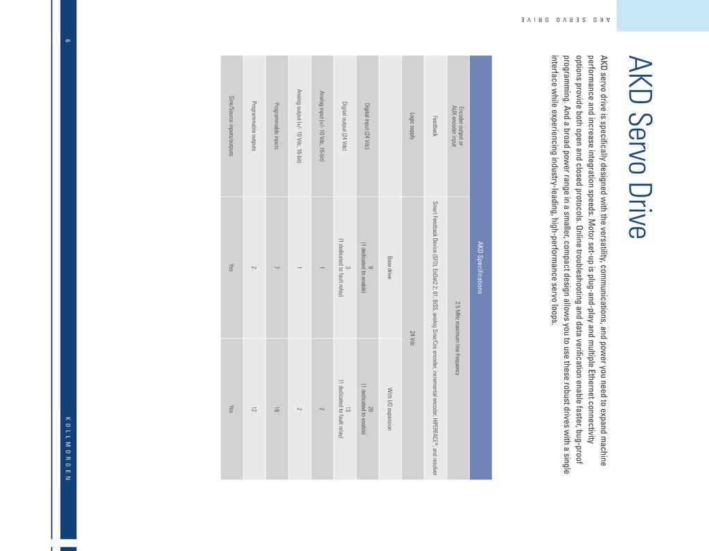
6 AKD Servo Drive A K D S E R V O D R I V E The AKD servo drive delivers cutting-edge technology and performance with one of the most compact footprints in the industry. These feature-rich drives provide a solution for nearly any application, from basic torque-and-velocity applications, to indexing, to multi-axis programmable motion with embedded Kollmorgen Automation Suite. The versatile AKD sets the standard for power density and performance. Micron Gearheads AKM Servomotors Cartridge Direct Drive Rotary Motors Housed Direct Drive Rotary Motors Best-in-Class Components AKD works seamlessly with Kollmorgen motors and positioners well-known for quality, reliability, and performance. Direct Drive Linear Motors* Linear Positioners Multi-Axis Precision Tables AKD Servo Drive * For more information on our direct drive linear motors, visit 4 K O L L M O R G E N

7
8
 Internal Regen (Watts) (Ohms) Height mm (in) Width mm (in) Depth mm (in) Depth with Cable Bend Radius mm (in) AKD- 00306 3 9 1100 0 0 168 (6.61) 57 (2.24) 153 (6.02) 184 (7.")
 230 (9.06) 265 (10.")
9 H D W General Specifications Industry-leading power density Modbus/TCP A K D S E R V O D R I V E 120 / 240 Vac 1 & 3Ø ( V) Continuous Current (Arms) Peak Current (Arms) Drive Continuous Output Power Capacity (Watts) Internal Regen (Watts) (Ohms) Height mm (in) Width mm (in) Depth mm (in) Depth with Cable Bend Radius mm (in) AKD (6.61) 57 (2.24) 153 (6.02) 184 (7.24) AKD (6.61) 57 (2.24) 153 (6.02) 184 (7.24) AKD (7.68) 76 (2.99) 186 (7.32) 215 (8.46) AKD (9.84) 100 (3.94) 230 (9.06) 265 (10.43) 480 Vac 3Ø ( V) Continuous Current (Arms) Peak Current (Arms) Drive Continuous Output Power Capacity (Watts) Internal Regen (Watts) (Ohms) Height mm (in) Width mm (in) Depth mm (in) Depth with Cable Bend Radius mm (in) AKD (10.08) 70 (2.76) 186 (7.32) 221 (8.70) AKD (10.08) 70 (2.76) 186 (7.32) 221 (8.70) AKD (10.08) 70 (2.76) 186 (7.32) 221 (8.70) AKD , (12.20) 105 (4.13) 229 (9.02) 264 (10.39) AKD , Coming Soon AKD , Coming Soon Note: For complete AKD model nomenclature, refer to page 63. w w w. k o l l m o r g e n. c o m 7


10 Scalable Programmability A K D S E R V O D R I V E The AKD servo drive delivers cutting-edge technology and performance with one of the most compact footprints in the industry. The AKD is flexible enough for virtually any application. From one axis that is as simple as analog torque and velocity, to 128 axes of fully programmable synchronized motion, AKD is the answer. Benefits Optimized performance in seconds Greater throughput and accuracy Easy-to-use Graphical User Interface (GUI) for faster commissioning and troubleshooting Flexible and scalable to meet any application BASiC Programmable 1.5 Axis Drive ( T Option) Base AKD ( B Option) Controlled by analog torque-and-velocity commands Includes electronic gearing via X9 connector Includes access to 11 digital I/O and 2 analog I/O on base drive Includes 2 high-speed digital inputs Expandable to 31 digital I/O and 4 analog I/O Motion Tasking ( P Option) Adds simple point-and-click indexing to base drive Provides user with pre-programmed options Guides novice user through simplified steps to create indexing moves Includes access to 11 digital I/O and 2 analog I/O on base drive Includes 2 high-speed digital inputs Expandable to 31 digital I/O and 4 analog I/O Same package size as base drive Adds BASIC programmability to base AKD Greater functionality than simple indexing Includes access to 11 digital I/O and 2 analog I/O on base drive Includes 2 high-speed digital inputs Expandable to 31 digital I/O and 4 analog I/O Same package size as base drive Basic Operation Single-Axis 8 K O L L M O R G E N
 Kollmorgen Automation Suite Programmable Drive Powerful 1.5 axis controller: new standard for performance!")
11 R A N G E O F K O L L M O R G E N A U T O M A T I O N S U I T E C A P A B I L I T I E S PC-Based Control A K D S E R V O D R I V E Optional HMI AKD Slaves Kollmorgen Automation Suite Programmable Automation Controller (PAC) Kollmorgen Automation Suite Programmable Drive Powerful 1.5 axis controller: new standard for performance! All five IEC languages (structured text, function block diagram, ladder diagram, instruction list, sequential function chart) for process programming (soft PLC) PLCopen for motion programming Exclusive function blocks such as wait and interrupt so your program can act as a scanning language or sequential language Includes access to 11 digital I/O and 2 analog I/O on base drive Includes 2 high-speed digital inputs Expandable to 31 digital I/O and 4 analog I/O Same package size as base drive AKD Master AKD Slaves Kollmorgen Automation Suite Programmable Multi-Axis Master True synchronized-path control of up to 4 axes Sets new standards for precision and optimizes nearly any application Easily manages remote I/O via EtherCAT in addition to all drives I/O Pipe Network program sophisticated camming and gearing applications in a matter of minutes Adds only 30 millimeters to width of drives below 12 Amps; same size as larger base drives Includes 11 digital I/O and 2 analog I/O per axis Includes 2 high-speed digital inputs per axis Capable of controlling up to 128 axes using a PAC and EtherCAT-enabled base AKD Easily manages remote I/O via EtherCAT in addition to all drives I/O Sets new standards for precision and optimizes nearly any application Pipe Network program sophisticated camming and gearing applications in a matter of minutes Adds only 30 millimeters to width of drives below 12 Amps; same size as larger base drives Includes 11 digital I/O and 2 analog I/O per axis Includes 2 high-speed digital inputs per axis IEC with five languages for process programming (soft PLC) Choice of PLCopen or Kollmorgen exclusive Pipe Network for motion programming Using the exclusive Pipe Network provides a one-to-one translation of a mechanical system into a logical world. Programming Multi-Axis Programming w w w. k o l l m o r g e n. c o m 9


12 Kollmorgen WorkBench A K D S E R V O D R I V E Our simple Graphical User Interface (GUI), Kollmorgen WorkBench, is designed to expedite and streamline the user s experience with the AKD servo drive. From easy application selection and reduced math, to a sleek six-channel scope; the user interface is extremely easy to use. Kollmorgen WorkBench supports intuitive access to the exclusive Performance Servo Tuner (PST) available inside AKD. The patent pending PST makes auto-tuning the AKD high-performance servo drive with world-class Kollmorgen motors very simple. User-Friendly Environment Logical flow, colorful icons and easy access simplify interactions with the AKD servo drive. The folder structure allows for instant identification and easy navigation. Sleek Six-Channel Real-Time Software Oscilloscope The easy-to-use AKD servo drive interface has a sleek digital oscilloscope that provides a comfortable environment for users to monitor performance. There are multiple options to share data in the format you prefer at the click of a button. Save as an image Load to an Print 10 K O L L M O R G E N


13 Application Selection Simplifies set-up by allowing use of machine or application-based units. Nip roller and rack and pinion set-ups shown. Nip Roller Application Selection Rack and Pinion Application Selection A K D S E R V O D R I V E Data-Sharing The ease-of-sharing continues in the parameters window. Kollmorgen WorkBench provides the user the easy options of printing or ing the parameter values at the click of a button. w w w. k o l l m o r g e n. c o m 11

 (IEC 61800 SIL2) Switches off the power stage to ensure personnel safety and prevents an unintended restart of the drive, even in fault condition Allows logic and")
 Simplifies system components Saves overhead of")
14 AKD Connector Layout and Functionality A K D S E R V O D R I V E Ethernet Connectivity Ethernet-based AKD servo drive provides the user with multiple bus choices EtherCAT (DSP402 protocol), Modbus/TCP, SynqNet, and CANopen No option cards are required industrial Design Rugged circuit design and compact enclosure for space-saving, modern appearance minimizes electrical noise emission and susceptibility Full fault protection UL, cul listed, and CE No external line filters needed (480 Vac units) for CE & UL compliance Removable screw terminal connectors for easy connections DC Bus sharing Safe-Torque-Off (STO) (IEC SIL2) Switches off the power stage to ensure personnel safety and prevents an unintended restart of the drive, even in fault condition Allows logic and communication to remain on during power stage shut down Plug-and-Play with Kollmorgen Motors and Positioners Electronic motor nameplates allow parameters to automatically load for fast commissioning Motion in seconds Custom motor parameters easily entered internal Regenerative Braking Resistor (All powers except 120/240 Vac 3 Arms and 6 Arms) Simplifies system components Saves overhead of managing external regeneration when internal regeneration is sufficient Performance Servo Tuner (PST) Exclusive patent pending auto-tuner reaches optimized set-up in seconds Handles inertia mismatches up to 1000:1 Industry leading bandwidth under compliant and stiff load conditions, no matter the mechanical bandwidth of the machine i/o (Base Drive) 8 digital inputs (1 dedicated to enable) 2 high-speed digital inputs (maximum time delay of 1.0 μs) 3 digital outputs (1 dedicated to fault relay) 1 analog input - 16 bit 1 analog output - 16 bit Modbus/TCP 12 K O L L M O R G E N
 Ground Stud X10 Feedback AKD 480 Vac Connector Layout X1 24")
 DC Bus Brake Resistor (DC Bus Sharing Mating Connector Option Shown) X7 / X8 I/O X4 Power Supply X10 Feedback Physical Earth (PE) Ground Stud X9 Encoder Emulation w w w. k o l l m o r g e n.")
15 AKD 120/240 Vac Connector Layout X2 Motor Holding Brake X3 (7 Pin) Power Supply DC Bus Brake Resistor X1 24 Vdc Supply STO Enable IEC SIL2 X12 / X13 CANopen (CiA certified) X11 Service Channel Modbus/TCP X5/ X6 Motion Bus EtherCAT SynqNet A K D S E R V O D R I V E X7 / X8 I/O X9 Encoder Emulation Physical Earth (PE) Ground Stud X10 Feedback AKD 480 Vac Connector Layout X1 24 Vdc Supply STO Enable IEC SIL2 X12 / X13 CANopen (CiA certified) X11 Service Channel Modbus/TCP X2 Motor Holding Brake (Cable Clamp Option Shown) X5/ X6 Motion Bus EtherCAT SynqNet X3 (4 Pin) DC Bus Brake Resistor (DC Bus Sharing Mating Connector Option Shown) X7 / X8 I/O X4 Power Supply X10 Feedback Physical Earth (PE) Ground Stud X9 Encoder Emulation w w w. k o l l m o r g e n. c o m 13


16 Accessories A K D S E R V O D R I V E CANopen Accessories We offer cables, terminators and adaptors for simple integration with CANopen machine networks. Brake Resistors We offer a full line of brake resistors up to 6000 watts. Brake resistors are impedance matched with AKD and are available in many sizes and form factors. LEFT: Line filter RIGHT: Motor choke Shielding Solutions AKD servo drive can be equipped with shielding plates. Chokes and Filters Line filters are offered to improve reliability and to protect the life of the machine in less stable environments. Motor chokes reduce radiated emissions and are recommended for applications with cable lengths >25 meters. RIGHT: Pre-Configured LEFT: Field Installable Screw lock adapter for auxiliary connection Motion Bus and Service Port Cables We offer industrial shielded PUR cables with RJ45 connections for demanding industrial environments. These cables outperform office cables in EMC resilience, durability, and life. i/o Control Box and Breakout Adapter Our I/O control box is pre-populated with I/O switches and a power connection for quicker prototyping. 14 K O L L M O R G E N

 12 A 24 A Static flex radius 10 x Cable")
17 Servo System Cables Value Line power and feedback cables are suitable for most standard applications. High-performance Flex Line power and feedback cables are available for trailing and flexing applications or where longer lengths are required. Mating Connectors AKD servo drives include screw type mating connectors. Alternative connectors for DC Bus and mains sharing are also available. D-sub and RJ-type connectors are not included. A K D S E R V O D R I V E Specification Comparison Value Line Flex Line Lengths offered 1, 3, 6, 9, 12 m 1-50 m, 1/2 m increments Max ampacity (continuous) 12 A 24 A Static flex radius 10 x Cable outside dimension (OD) 10 x Cable outside dimension (OD) Dynamic flex (1,000,000 cycles) Not rated 15 x Cable outside dimension (OD) Motor connectors available Euro style Euro style Maximum motor connector IP rating IP67 IP65 Cable agency approvals RoHS, UL, CE UL, CSA, CE, NEC, NFPA Feedback supported SFD, EnDat2.2, 01, BiSS, resolver, HIPERFACE SFD, Sine Encoder, EnDat2.2, 01, BiSS, resolver, HIPERFACE, comcoder Holding brake Available Available Power Cables AKD Servo Drive Value Line OD (mm) Value Line with Brake OD (mm) Flex Line OD (mm) Flex Line with Brake OD (mm) 3/6 Amp VP-507BEAN-XX 9.4 VP-508CFAN-XX 10.9 CP-507CCAN-XX-X 12.7 CP-507CDAN-XX-X Amp VP-508CEAN-XX 10.3 VP-508CFAN-XX 10.9 CP-507CCAN-XX-X 12.7 CP-507CDAN-XX-X Amp VP-508DEAN-XX 11.7 VP-508DFAN-XX 12.9 CP-508DCAN-XX-X 14.5 CP-508DDAN-XX-X Amp Not available Not available Not available Not available CP-508EDBN-XX-X 18.3 CP-508EDBN-XX-X 18.3 Feedback Cables Feedback Type Value Line OD (mm) Flex Line OD (mm) SFD VF-DA0474N-XX 6.7 CF-DA0374N-XX-X 7.5 EnDat 2.1 / BiSS, HIPERFFACE VF-SB4474N-XX 9.7 CF-SB7374N-XX-X 11.2 Resolver VF-RA2474N-XX 9.7 CF-RA2574N-XX-X 9.5 Incremental / comcoder Not available Not available CF-CB7374N-XX-X 11.2 Note: Refer to page 62 for matching cables by motor type and drive. w w w. k o l l m o r g e n. c o m 15
18 A K D S E R V O S Y S T E M S AKD Servo Systems When you need precise position control, choose from Kollmorgen s broad portfolio of AKD servo system components. Our unparalleled product line breadth provides great flexibility for any application. Whether it s any combination of motors and drives, cables, controller, electric cylinders or gearheads, all components are plug-and-play for easy, seamless integration. These best-in-class servo systems can be matched with single-axis or multi-axis motion controllers for a system solution that s precise, reliable and durable. 16 K O L L M O R G E N
19 The Benefits of AKD Servo Systems A K D S E R V O S Y S T E M S Optimized AKM and Direct Drive Motor Windings to AKD Servo Drive Plug-and-Play Motor-Recognition Drive Commissioning for AKM, Cartridge DDR, and DDR Motor Families Industry-Leading and Patent Pending Auto-Tuning Algorithms New Lower Cost Multi-Turn Feedback Option Industry-Leading Motor Power Density AKM Servomotor Offers 28 Frame-Stack Combinations and Nearly 120 Standard Windings in a Single Motor Line Cartridge DDR Motor Offers 17 Frame-Stack Combinations and 31 Windings Cartridge DDR Motor Offers 12 Frame-Stack Combinations and 12 Windings New IP67 Protection Class Option for AKM Same size AKM servomotor delivers up to 47% more shaft power than before Reduction in drive size and motor size Reduction in system cost Reduction in set-up time for each servo system Immediate and adaptive response to dynamic loads optimizes performance in seconds Precise control of all motor types Compensation for stiff and compliant transmissions and couplings Improve machine precision with high resolution and improved accuracy Reduce cycle time and sensor-and-wiring costs by eliminating traditional homing methods Don t let motor size dictate the size of your machine Fit more motor into a smaller space than you thought possible Over 50,000 standard motor variations including a wide range of mounting, connectivity, feedback and other options Flexibility provides choices to help you find an exact-fit solution Simplifies or eliminates mechanical modifications and engineering adaptation Apply AKM servomotor into hostile industrial applications with confidence and long-term reliability w w w. k o l l m o r g e n. c o m 17


20 AKM Servomotor A K D S E R V O S Y S T E M S A K M S E R V O M O T O R The AKM brushless servomotor stands alone in the marketplace in terms of flexibility and performance advantages. Kollmorgen s culture of continuous improvement has paid dividends again. The AKM servomotor s innovative design has been polished and optimized. With the new AKD servo drive amplifier, the AKM servomotor sets a new standard of refined servo performance, designed to deliver precise motion and more power for your money. Nowhere else will you find a more versatile and complete servo family to meet your needs and exceed your expectations. AKM Features 0.16 to 180 Nm continuous stall torque (1.4 to 1590 lb-in) Eight frame sizes (40 to 260 mm) 28 frame-stack length combinations 117 standard windings tailored for 75 Vdc and 120/240/400/480 Vac operation Flexible flange mount and shaft options Industry-leading low-cogging contributing to extreme smoothness Numerous feedback options for high-performance and precision or rugged environment Unmatched customization special windings, special shafts, and much more AKD Servo Drive with AKM Servomotor Plug-and-Play Feedback These feedback devices include electronic motor nameplates allowing plug-and-play commissioning, eliminating the need for drive parameter set-up and servo loop tuning in most applications. Performance Data AKM Servomotor Single-turn Absolute Accuracy (arc-min) Resolution (bits) Motor Key Multi-turn Absolute Accuracy (arc-min) Resolution (bits) Motor Key AKM C AKM C 8 20 LB AKM C LB AKM DA DB AKM DA DB 18 K O L L M O R G E N

21 AKM (Exploded) 3D Model Shows Key Design Features Brake splines cut directly into shaft eliminates loosening of brake hub Integrated front-endbell improves structural rigidity and sealing Modular brake eliminates friction surface contamination and mistakes in air-gap setting Multiple feedback devices to meet your application needs A K D S E R V O S Y S T E M S A K M S E R V O M O T O R Captured front bearing eliminates axial movement Rugged powder-coating and proper O-ring seals protect the motor from harsh environments Thru-mount design allows installation in tight spaces Optimized electro-magnetic design for torque-density and best-in-class cogging w w w. k o l l m o r g e n. c o m 19
22 AKM Servomotor A K D S E R V O S Y S T E M S A K M S E R V O M O T O R Performance Data AKM Servomotor 120 Vac 240 Vac AKD Servo Drive Frame Size NEMA/ mm Cont.Torque at stall Tcs Nm (lb-in) Note 1: Refer to page 62 for matching cables. Note 2: For complete AKD and AKM model nomenclature, refer to pages 63 and 64 respectively. Note 3: Max mechanical speeds: 8000 RPM for AKM1, 2, 3 and 6000 RPM for AKM4, 5, 6, 7. Peak Torque at stall Tps Nm (lb-in) Rated Speed Nrtd RPM Max System Speed RPM Power Prtd Watts Inertia (Jm) Kg-cm 2 (lb-in-s 2 x10⁻² ) AKM11B AKD-X / (1.59) 0.61 (5.4) (0.0015) AKM11C AKD-X / (1.68) 0.62 (5.5) (0.0015) AKM12C AKD-X / (2.74) 1.08 (9.56) ( ) AKM12E AKD-X / (2.74) 0.91 (8.05) ( ) AKM13C AKD-X / (3.63) 1.46 (12.9) (0.0040) AKM13D AKD-X / (3.54) 1.36 (12.0) (0.0040) AKM21C AKD-X / (4.25) 1.48 (13.1) (0.0095) AKM21E AKD-X / (4.16) 1.21 (10.7) (0.0095) AKM22C AKD-X / (7.43) 2.39 (21.2) (0.0142) AKM22E AKD-X / (7.70) 2.42 (21.4) (0.0142) AKM23D AKD-X / (10.2) 3.89 (34.4) (0.0191) AKM23F AKD-X / (10.4) 3.88 (34.3) (0.0191) AKM24D AKD-X / (12.4) 4.84 (42.8) (0.0239) AKM24F AKD-X / (12.5) 4.82 (42.7) (0.0239) AKM31E AKD-X00306 na/ (10.6) 3.23 (28.6) (0.0292) AKM32E AKD-X00306 na/ (18.1) 5.97 (52.8) (0.0522) AKM32H AKD-X00606 na/ (18.6) 6.22 (55.1) (0.0522) AKM33H AKD-X00606 na/ (25.4) 8.55 (75.7) (0.0752) AKM41E AKD-X / (17.8) 5.33 (47.2) (0.0717) AKM41H AKD-X / (18.1) 5.49 (48.6) (0.0717) AKM43H AKD-X / (42.7) 14.0 (124) (0.185) AKM43L AKD-X / (41.9) 11.7 (104) (0.185) AKM44H AKD-X / (43.3) 17.0 (150) (0.242) AKM51H AKD-X / (42.4) 11.7 (104) (0.303) AKM51L AKD-X / (43.3) 10.6 (93.8) (0.303) AKM52L AKD-X / (76.7) 19.6 (173) (0.551) AKM53L AKD-X / (103) 26.5 (235) (0.807) AKM54L AKD-X / (119) 31.3 (277) (1.06) AKM11B AKD-X / (1.59) 0.61 (5.4) (0.0015) AKM12C AKD-X / (2.74) 1.08 (9.56) ( ) AKM13C AKD-X / (3.63) 1.46 (12.9) (0.0040) AKM21C AKD-X / (4.25) 1.48 (13.1) (0.0095) AKM22C AKD-X / (7.43) 2.73 (24.2) (0.0142) AKM22E AKD-X / (7.70) 2.42 (21.4) (0.0142) AKM23D AKD-X / (10.2) 3.89 (34.4) (0.0191) AKM23F AKD-X / (10.4) 3.88 (34.3) (0.0191) AKM24D AKD-X / (12.4) 4.84 (42.8) (0.0239) AKM24F AKD-X / (12.5) 4.82 (42.7) (0.0239) AKM31C AKD-X00306 na/ (10.2) 3.87 (34.3) (0.0292) AKM31E AKD-X00306 na/ (10.6) 3.23 (28.6) (0.0292) AKM32E AKD-X00306 na/ (18.1) 5.97 (52.8) (0.0522) AKM32H AKD-X00606 na/ (18.6) 6.22 (55.1) (0.0522) AKM33E AKD-X00306 na/ (24.8) 8.95 (79.2) (0.0752) AKM33H AKD-X00606 na/ (25.4) 8.55 (75.7) (0.0752) AKM41E AKD-X / (17.8) 5.33 (47.2) (0.0717) AKM41H AKD-X / (18.1) 5.49 (48.6) (0.0717) AKM42E AKD-X / (30.3) 9.74 (86.2) (0.128) AKM42G AKD-X / (31.1) 11.0 (97.4) (0.128) AKM43H AKD-X / (42.7) 14.0 (124) (0.185) AKM43L AKD-X / (41.9) 11.7 (104) (0.185) AKM44E AKD-X / (51.2) 16.5 (146) (0.242) AKM44H AKD-X / (43.3) 17.0 (150) (0.242) 20 K O L L M O R G E N
23 Performance Data AKM Servomotor 240 Vac AKD Servo Drive Frame Size NEMA/ mm Cont.Torque at stall Tcs Nm (lb-in) Peak Torque at stall Tps Nm (lb-in) Rated Speed Nrtd RPM Max System Speed RPM Power Prtd Watts Inertia (Jm) Kg-cm 2 (lb-in-s 2 x10⁻² ) AKM51H AKD-X / (42.4) 11.7 (104) (0.303) AKM51L AKD-X / (43.3) 10.6 (93.8) (.0303) AKM52H AKD-X / (75.1) 21.6 (191) (0.551) AKM52L AKD-X / (76.7) 19.6 (173) (0.551) AKM53H AKD-X / (92.9) 27.8 (246) (0.807) AKM53L AKD-X / (103) 26.5 (235) (0.807) AKM54H AKD-X / (126) 37.5 (332) (1.06) AKM54L AKD-X / (119) 31.3 (277) (1.06) AKM62H AKD-X00606 na/ (105) (262) (1.50) AKM62L AKD-X01206 na/ (108) 26.3 (233) (1.50) AKM63L AKD-X01206 na/ (149) 39.3 (348) (2.14) AKM63N AKD-X02406 na/ (150) 40.3 (357) (2.14) AKM64L AKD-X01206 na/ (174) 44.4 (393) (2.80) AKM64Q AKD-X02406 na/ (173) 43.1 (381) (2.80) AKM65L AKD-X01206 na/ (218) 55.4 (490) (3.54) AKM65P AKD-X02406 na/ (217) 53.9 (477) (3.54) AKM72P AKD-X02406 na/ (261) 65.8 (606) (5.71) AKM72Q AKD-X02406 na/ (217) 56.0 (496) (5.71) AKM73P AKD-X02406 na/ (366) 95.3 (828) (8.15) AKM73Q AKD-X02406 na/ (292) 76.1 (674) (8.15) AKM74Q AKD-X02406 na/ (414) 90.7 (803) (10.6) AKM22C AKD-X / (7.43) 2.73 (24.2) (0.0142) AKM23D AKD-X / (10.2) 3.89 (34.4) (0.0191) AKM24D AKD-X / (12.4) 4.84 (42.8) (0.0239) AKM31C AKD-X00307 na/ (10.2) 3.87 (34.3) (0.0292) AKM32E AKD-X00307 na/ (18.1) 5.97 (52.8) (0.0522) AKM33E AKD-X00307 na/ (24.8) 8.95 (79.2) (0.0752) AKM41E AKD-X / (17.8) 5.33 (47.2) (0.0717) AKM42E AKD-X / (30.3) 9.74 (86.2) (0.128) AKM42G AKD-X / (31.1) 11.0 (97.4) (0.128) AKM43H AKD-X / (42.7) 14 (124) (0.185) AKM44E AKD-X / (51.2) 16.5 (146) (0.242) AKM44H AKD-X / (43.3) 17.0 (150) (0.242) AKM51H AKD-X / (42.4) 11.7 (104) (0.303) AKM52H AKD-X / (75.1) 21.6 (191) (0.551) AKM52L AKD-X / (76.7) 19.6 (173) (0.551) AKM53H AKD-X / (92.9) 27.8 (246) (0.807) AKM53L AKD-X / (103) 26.5 (235) (0.807) AKM54H AKD-X / (126) 37.5 (332) (1.06) AKM54L AKD-X / (119) 31.3 (277) (1.06) AKM62H AKD-X00607 na/ (105) 29.6 (262) (1.50) AKM62L AKD-X01207 na/ (108) 26.3 (233) (1.50) AKM63L AKD-X01207 na/ (149) 39.3 (348) (2.14) AKM63N AKD-X02407 na/ (150) 40.3 (357) (2.14) AKM64L AKD-X01207 na/ (174) 44.4 (393) (2.80) AKM64Q AKD-X02407 na/ (173) 43.1 (381) (2.80) AKM65L AKD-X01207 na/ (218) 55.4 (490) (3.54) AKM65P AKD-X02407 na/ (217) 53.9 (477) (3.54) AKM72L AKD-X01207 na/ (266) 70.5 (624) (5.71) AKM72P AKD-X02407 na/ (261) 68.5 (606) (5.71) AKM72Q AKD-X02407 na/ (217) 56.0 (496) (5.71) AKM73L AKD-X01207 na/ (369) 95.4 (844) (8.15) AKM73P AKD-X02407 na/ (366) 93.5 (828) (8.15) AKM73Q AKD-X02407 na/ (292) 76.1 (674) (8.15) AKM74L AKD-X01207 na/ (440) 114 (1010) (10.6) AKM74P AKD-X02407 na/ (463) 125 (1110) (10.6) AKM74Q AKD-X02407 na/ (414) 90.7 (803) (10.6) Note 1: Refer to page 62 for matching cables. Note 2: For complete AKD and AKM model nomenclature, refer to pages 63 and 64 respectively. Note 3: Max mechanical speeds: 8000 RPM for AKM1, 2, 3 and 6000 RPM for AKM4, 5, 6, Vac A K D S E R V O S Y S T E M S A K M S E R V O M O T O R w w w. k o l l m o r g e n. c o m 21
24 AKM Servomotor A K D S E R V O S Y S T E M S A K M S E R V O M O T O R Performance Data AKM Servomotor AKD Servo Drive Frame Size NEMA/ mm Cont.Torque at stall Tcs Nm (lb-in) Peak Torque at stall Tps Nm (lb-in) Rated Speed Nrtd RPM Max System Speed RPM Power Prtd Watts Inertia (Jm) Kg-cm 2 (lb-in-s 2 x10⁻² ) AKM22C AKD-X / (7.43) 2.34 (20.7) (0.0142) AKM23D AKD-X / (10.2) 3.89 (34.4) (0.0191) AKM24D AKD-X / (12.4) 4.84 (42.8) (0.0239) AKM31C AKD-X00307 na/ (10.2) 3.35 (29.7) (0.0292) AKM32E AKD-X00307 na/ (18.1) 5.97 (52.8) (0.0522) AKM33E AKD-X00307 na/ (24.8) 8.95 (79.2) (0.0752) AKM41E AKD-X / (17.8) 5.33 (47.2) (0.0717) AKM42E AKD-X / (30.3) 9.74 (86.2) (0.128) AKM42G AKD-X / (31.1) 11.0 (97.4) (0.128) AKM43H AKD-X / (42.7) 14.0 (124) (0.185) AKM44E AKD-X / (51.2) 16.5 (146) (0.242) AKM44H AKD-X / (43.3) 17.0 (150) (0.242) AKM51H AKD-X / (42.4) 11.7 (104) (0.303) AKM52H AKD-X / (75.1) 21.6 (191) (0.551) AKM52L AKD-X / (76.7) 19.6 (173) (0.551) AKM53H AKD-X / (92.9) 27.8 (246) (0.807) AKM53L AKD-X / (103) 26.5 (235) (0.807) 480 Vac AKM54H AKD-X / (126) 37.5 (332) (1.06) AKM54L AKD-X / (119) 31.3 (277) (1.06) AKM62H AKD-X00607 na/ (105) 29.6 (262) (1.50) AKM62L AKD-X01207 na/ (108) 26.3 (233) (1.50) AKM63L AKD-X01207 na/ (149) 39.3 (348) (2.14) AKM63N AKD-X02407 na/ (150) 40.3 (357) (2.14) AKM64L AKD-X01207 na/ (174) 44.4 (393) (2.80) AKM64Q AKD-X02407 na/ (173) 43.1 (381) (2.80) AKM65L AKD-X01207 na/ (218) 55.4 (490) (3.54) AKM65P AKD-X02407 na/ (217) 53.9 (477) (3.54) AKM72L AKD-X01207 na/ (266) 70.5 (624) (5.71) AKM72P AKD-X02407 na/ (261) 68.5 (606) (5.71) AKM72Q AKD-X02407 na/ (217) 56.0 (496) (5.71) AKM73L AKD-X01207 na/ (369) 95.4 (844) (8.15) AKM73P AKD-X02407 na/ (366) 93.5 (828) (8.15) AKM73Q AKD-X02407 na/ (292) 76.1 (674) (8.15) AKM74L AKD-X01207 na/ (440) 114 (1010) (10.6) AKM74P AKD-X02407 na/ (463) 125 (1110) (10.6) AKM74Q AKD-X02407 na/ (414) 90.7 (803) (10.6) Note 1: Refer to page 62 for matching cables. Note 2: For complete AKD and AKM model nomenclature, refer to pages 63 and 64 respectively. Note 3: Max mechanical speeds: 8000 RPM for AKM1, 2, 3 and 6000 RPM for AKM4, 5, 6, K O L L M O R G E N
25 Model with Power Connector Outline indicative of AKM11 - AKM74 K ØJ Model with Terminal Box Outline indicative of AKM82 - AKM84 ØJ K ØD 4XØC B B A K D S E R V O S Y S T E M S A K M S E R V O M O T O R 4XØC Dimensions (mm) Model Shaft ** Shaft Length Mount Hole ** 1 stack Length (AKMx1) Length 2 stack (AKMx2) Length 3 stack (AKMx3) Length 4 stack (AKMx4) Length 5 stack (AKMx5) J K C Y Y Y Y Y Brake Adder Sine Enc. Adder * AKM n/a n/a n/a n/a AKM n/a AKM n/a n/a AKM n/a AKM n/a AKM n/a AKM n/a n/a AKM n/a n/a 66 0 Model Frame Square B Mount Pilot ** Mount B.C. ** AKM AKM AKM AKM Model Frame Square B Mount Pilot ** Mount B.C. ** AKM AKM AKM AKM * AKM5x w/ Sine Enc. and brake, plus adders, -2.0 mm. AKM6x w/ Sine Enc. and brake, plus adders, +0.5 mm. AKM7x w/ Sine Enc. and brake, plus adders, +9.3 mm. ** Assumes the A international mount, other mounts available see AKM selection guide online. w w w. k o l l m o r g e n. c o m 23
26 Direct Drive Technology A K D S E R V O S Y S T E M S D I R E C T D R I V E T E C H N O L O G Y Conventional servo systems commonly have a mechanical transmission which can consist of gears, gearheads, belts/pulleys or cams connected between the motor and the load. With direct drive technology, the mechanical transmission is eliminated and the motor is coupled directly to the load. Why Use Direct Drive Technology? increased Accuracy and Repeatability A precision planetary gearhead could have a backlash of 1 arc-minute. This can result in the load moving by 1 arc-minute with an absolutely stationary drive motor. Kollmorgen s standard direct drive rotary (DDR) servomotors have repeatability better than 1 arc-second. Therefore, a direct drive motor can hold a position 60 times better than a conventional motor/gearhead. The increased accuracy of direct drive technology results in a higher quality product out of the machine: Print registration is more accurate Cut or feed lengths can be held more precisely Coordination with other machine axes is more accurate Indexing location is more exact Tuning issues due to backlash are eliminated Higher Bandwidth Mechanical transmission components impose a limit on how fast a machine can start and stop and also extend the required settling time. These factors limit the possible throughput of a machine. Direct drive technology removes these limitations and allows for much faster start/stop cycles and also provides greatly reduced settling time. This will allow a greater throughput from the machine. Users of direct drive systems have reported up to a 2X increase in throughput. Gearbox Motor Servomotor and gearhead Direct drive motor 1 Arc 0 Minutes -1 Improved repeatability Gearbox Backlash DDR Repeatability 60 Times Better improved Reliability and Zero Maintenance Gears, belts, and other mechanical transmission parts break. By eliminating these parts and using DDR motors, the reliability of the machine is improved. Gearheads require periodic lubrication and/or replacement in aggressive start/stop applications. Belts require periodic tightening. There are no time-wear components in a direct drive motor and consequently they require zero maintenance. Conventional rotary servo with mechanical transmission DDR motors provide higher throughput because start/stop limitations of mechanical transmissions are eliminated Increased throughput 24 K O L L M O R G E N
27 Fewer Parts With direct drive motors, all you need is the motor and the mounting bolts. This often replaces many parts including brackets, guards, belts, pulleys, tensioners, couplings, and bolts, resulting in: Fewer parts on the BOM. Fewer parts to purchase, schedule, inventory and control, and fewer parts to assemble. Assembly time of the servo drops from several hours with the mechanical transmission to several minutes with the DDR. Reduced cost. Although a direct drive motor may carry a small price-premium compared to a motor/gearhead with the same torque, consider that there is an overall cost reduction when eliminating the parts and labor of all the extra components required in a servo system with mechanical transmission. No inertia Matching Servo systems with mechanical transmissions require inertia matching that limits the reflected load inertia at five to ten times the motor inertia. If this limitation is not met, the system becomes difficult to control due to instability issues. Inertia matching limitations of mechanical transmission systems often force machine designers to use a larger motor than would otherwise be required just to satisfy the inertia matching requirement. Such sizing conventions are not required with direct drive technology. Since the motor is directly connected to the load, the inertia of the motor and the load become a common inertia. Therefore, no inertia matching is required when using DDR. DDR applications have run with inertia ratios greater than 11,000:1. Reduced Audible Noise Machines with DDR motors have audible noise levels as low as 20 db less than the same machine with a mechanical transmission. Three DDR Product Categories to Choose From Kollmorgen s 50 years of electromagnetic and electromechanical design experience combined with our quality and service, allowed us to refine and expand DDR technology into three product categories for easy installation, use, and short lead times: KBM Frameless DDR, Housed DDR, and the Cartridge DDR. This allows you to select the right DDR solution for your application. KBM Series Frameless DDR Frameless motors include a rotor and stator as separate components which are integrated into, ride on the bearings of, and become a part of the driven load. Frameless motors offer the most compact and lightweight DDR solution available. The KBM series is Kollmorgen s latest frameless DDR product. It provides excellent torque/volume with the use of a proprietary neodymium-iron magnet rotor structure and skewed armature assembly. Housed DDR The Housed DDR is a housed motor assembly featuring a factory aligned high-resolution feedback device and precision bearings, allowing it to function as the core of rotary indexing and rate table applications. The system can also be used as a flexible indexer, providing programmable, rapid indexing far exceeding the throughput and accuracy of conventional mechanical or variable reluctance technology indexers. Cartridge DDR This motor is the first in the industry to combine the space-saving and performance advantages of frameless DDR technology with the ease of installation of a full-frame motor. Consisting of a rotor, stator, and factoryaligned high-resolution feedback device, the motor uses the machine s bearings to support the rotor. An innovative compression coupling engages the rotor to the load and the frame of the motor mounts to the machine with a bolt circle and pilot diameter just like a conventional servomotor, saving space and design time and simplifying the overall system. A K D S E R V O S Y S T E M S D I R E C T D R I V E T E C H N O L O G Y DDR Applications Format KBM Frameless DDR Housed DDR Cartridge DDR Where Used Application where size and weight must be absolutely minimized Applications where the load rides on the motor s bearings such as indexing or rate tables Any application with existing bearings w w w. k o l l m o r g e n. c o m 25


28 Cartridge Direct Drive Rotary (DDR) Motor A K D S E R V O S Y S T E M S C A R T R I D G E D I R E C T D R I V E R O T A R Y M O T O R The Cartridge Direct Drive Rotary (DDR) motor is the first in the industry to combine the space-saving and performance advantages of frameless DDR technology with the ease of installation of a fullframe motor. Cartridge DDR motors also feature an advanced electromagnetic design that provides up to 50% more torque density than comparably sized conventional servomotors. Consisting of a rotor, stator and factory-aligned high-resolution feedback device, the Cartridge DDR motor uses the machine s bearings to support the rotor. An innovative compression coupling secures the Cartridge DDR s rotor to the machine shaft, and the Cartridge DDR s housing is bolted to the machine frame with a bolt circle and pilot just like a conventional servomotor saving space and design time and simplifying the overall system. Conventional servo systems typically include a number of mechanical transmission components that limit the performance and reliability, and drive up cost of operation. Cartridge DDR motors eliminate all mechanical transmission parts, resulting in the following features: Cartridge DDR Features Assembles as quickly as five minutes Five frame sizes, multiple lengths Continuous torque range: 4.57 Nm (3.37 lb-ft) to 510 Nm (373 lb-ft), accommodates a wide range of high-power application requirements Optimized torque output with high-pole count efficient electromagnetic design Integrated high resolution sine encoder 134,217,728 counts/rev Speeds up to 2,500 RPM meets most medium speed and high-torque application requirements Direct load connection eliminates gearheads, belts and pulleys Low cogging for smooth low-speed rotation Zero backlash and compliance provides more responsive system performance 26 K O L L M O R G E N


29 The Cartridge DDR Advantage Press Feed Machine Consider how Cartridge DDR technology improves a press feed machine: Reduced Assembly Time The assembly time for the original mechanical transmission system was 4 hours. In contrast, the Cartridge DDR motor is installed in less than 5 minutes, resulting in a significant cost savings in labor. Reduced Parts Count The original mechanical transmission system comprises 2 bracket pieces, 12 bolts, 2 pulleys, 2 set screws, 2 keys, a timing belt, a housing to protect operators from the timing belt, a tension system for the timing belt, and motor/gearhead. With the Cartridge DDR system, this is all replaced by the motor and 4 mounting bolts, resulting in fewer parts to maintain and cost savings. improved Accuracy The best planetary gearheads have a backlash between 1 and 2 arcminutes. Over the life of the gearhead, the backlash will increase. The Cartridge DDR system has an absolute accuracy of 26 arc-seconds and a repeatability of 0.7 arc-seconds. The press feed machine with the Cartridge DDR has a feed accuracy of +/ inch where the press feed machine with the mechanical transmission has a feed accuracy of inch. Therefore, there was an overall four times improvement in machine accuracy with the Cartridge DDR system. increased Throughput The cycle rate of the Cartridge DDR system is two times better than the mechanical transmission. This results in an increase in throughput of 100 percent. improved Reliability and Simplified Maintenance The Cartridge DDR system eliminates parts that wear, change over time, or fail. Gearheads are prone to wear, and backlash increases over time. Belts and pulleys stretch and require maintenance to maintain proper belt tension. By eliminating these components, the Cartridge DDR system delivers greater system reliability. Press Feed Example Gearheads have a finite life span, especially in a demanding cyclic application such as a press feed. On this machine, the gearhead must be replaced every 10,000 hours and the belt must be tensioned every 2,000 hours. By contrast, the Cartridge DDR motor has no wear components and requires no maintenance thus simplifying the maintenance schedule for the machine, including operating costs. Reduced Audible Noise The Cartridge DDR system has as much as a 20 db reduction in noise compared to a mechanical transmission servo system. This can dramatically reduce the overall noise level of the machine. A quieter machine gives the perception of quality. This is rightfully so as the noise emitted by gears and belts is caused by the wearing of the parts. Total Reduced Cost A Cartridge DDR motor typically costs 20 percent more than a comparable motor/gearhead combination. However, the elimination of parts and assembly time typically results in a lower total cost for the Cartridge DDR solution. A K D S E R V O S Y S T E M S C A R T R I D G E D I R E C T D R I V E R O T A R Y M O T O R Press feed machine built with a conventional servomotor, gearhead, belt and pulleys. Same machine with a Cartridge DDR motor installed. Here, the shaft of the driven roll is extended into the Cartridge DDR motor and the motor applies torque directly to the driven roll. w w w. k o l l m o r g e n. c o m 27
30 Cartridge Direct Drive Rotary Motor (DDR) A K D S E R V O S Y S T E M S C A R T R I D G E D I R E C T D R I V E R O T A R Y M O T O R 240 Vac Performance Data Cartridge DDR Motor AKD Servo Drive Frame Size Continuous Torque Peak Torque Maximum Speed Weight Inertia (Jm) mm (in) Nm (lb-in) Nm (lb-in) RPM kg (lb) kg-cm 2 (lb-in-s 2 x10⁻³ ) C041A AKD-X (4.25) 4.57 (40.4) 12.3 (109) (9.00) 5.86 (5.19) C041B AKD-X (4.25) 4.52 (40.0) 12.2 (108) (9.00) 5.86 (5.19) C042A AKD-X (4.25) 8.25 (73.0) 22.2 (196) (12.5) 8.87 (7.85) C042B AKD-X (4.25) 8.45 (74.8) 22.8 (202) (12.5) 8.87 (7.85) C043A AKD-X (4.25) 11.1 (98.2) 30.0 (265) (16.0) 11.9 (10.5) C043B AKD-X (4.25) 11.2 (99.1) 30.2 (267) (16.0) 11.9 (10.5) C044A AKD-X (4.25) 13.9 (123) 37.4 (331) (19.5) 14.9 (13.2) C044B AKD-X (4.25) 14.1 (125) 37.9 (335) (19.5) 14.9 (13.2) C051A AKD-X (5.43) 11.7 (104) 30.2 (267) (18.5) 27.4 (24.2) C051B AKD-X (5.43) 11.9 (105) 30.6 (271) (18.5) 27.4 (24.2) C052C AKD-X (5.43) 16.9 (150) 43.1 (381) (23.5) 35.9 (31.8) C052D AKD-X (5.43) 16.5 (146) 42.3 (374) (23.5) 35.9 (31.8) C053A AKD-X (5.43) 21.0 (186) 54.1 (479) (29.0) 44.3 (39.2) C053B AKD-X (5.43) 20.2 (179) 50.1 (443) (29.0) 44.3 (39.2) C054A AKD-X (5.43) 24.9 (220) 63.8 (565) (34.0) 52.8 (46.7) C054B AKD-X (5.43) 23.8 (211) 61.2 (542) (34.0) 52.8 (46.7) C061A AKD-X (7.40) 33.8 (299) 86.8 (768) (41.0) 94.1 (83.2) C061B AKD-X (7.40) 32.6 (288) 75.6 (669) (41.0) 94.1 (83.2) C062C AKD-X (7.40) 48.4 (428) 117 (1040) (52.0) 126 (112) C062B AKD-X (7.40) 44.6 (395) 102 (900) (52.0) 126 (112) C063C AKD-X (7.40) 61.8 (547) 157 (1380) (63.0) 157 (139) C063B AKD-X (7.40) 59.0 (522) 136 (1200) (63.0) 157 (139) C091A AKD-X (9.68) 50.2 (444) 120 (1060) (61.0) 280 (248) C092C AKD-X (9.68) 102 (900) 231 (2050) (91.0) 470 (416) C093C AKD-X (9.68) 139 (1230) 317 (2800) (120) 660 (584) C131C AKD-X (13.8) 189 (1670) 395 (3500) (140) 1240 (1100) C132C AKD-X (13.8) 362 (3200) 818 (7240) (223) 2250 (1990) C133C AKD-X (13.8) 499 (4410) 1070 (9890) (292) 3020 (2670) 400/480 Vac Systems Performance Data Cartridge DDR Motor AKD Servo Drive Frame Size Continuous Torque Peak Torque Maximum Speed Weight Inertia (Jm) RPM kg-cm 2 (lb-in-s 2 x10⁻³ ) mm (in) Nm (lb-in) Nm (lb-in) 400 Vac 480 Vac kg (lb) CH041A AKD-X (4.25) 4.56 (40.4) 11.3 (100) (9.00) 5.86 (5.19) CH042A AKD-X (4.25) 8.26 (73.1) 19.0 (168) (12.5) 8.87 (7.85) CH043A AKD-X (4.25) 11.1 (98.2) 25.3 (224) (16.0) 11.9 (10.5) CH044A AKD-X (4.25) 13.9 (123) 31.6 (280) (19.5) 14.9 (13.2) CH051A AKD-X (5.43) 11.7 (104) 28.0 (248) (18.5) 27.4 (24.2) CH052C AKD-X (5.43) 16.9 (150) 43.1 (381) (23.5) 35.9 (31.8) CH053A AKD-X (5.43) 21.0 (186) 54.1 (479) (29.0) 44.3 (39.2) CH054A AKD-X (5.43) 24.9 (220) 63.8 (565) (34.0) 52.8 (46.7) CH061A AKD-X (7.40) 33.8 (299) 86.8 (768) (41.0) 94.1 (83.2) CH062C AKD-X (7.40) 48.4 (428) 117 (1040) (52.0) 126 (112) CH063C AKD-X (7.40) 61.8 (547) 157 (1380) (63.0) 157 (139) CH063B AKD-X (7.40) 59.0 (522) 136 (1200) (63.0) 157 (139) CH091A AKD-X (9.68) 50.2 (444) 120 (1060) (61.0) 280 (248) CH092C AKD-X (9.68) 102 (900) 231 (2050) (91.0) 470 (416) CH093C AKD-X (9.68) 139 (1230) 317 (2800) (120) 660 (584) CH131C AKD-X (13.8) 189 (1670) 395 (3500) (140) 1240 (1100) CH131B AKD-X04807* 350 (13.8) 190 (1680) 396 (3500) (140) 1240 (1100) CH132C AKD-X (13.8) 362 (3200) 818 (7240) (223) 2250 (1990) CH132B AKD-X04807* 350 (13.8) 361 (3190) 759 (6720) (223) 2250 (1990) CH133C AKD-X (13.8) 499 (4410) 1070 (9480) (292) 3020 (2670) CH133B AKD-X04807* 350 (13.8) 510 (4510) 1090 (9700) (292) 3020 (2670) Cartridge DDR C09 and C13 Dimensions Note 1: Refer to page 62 for matching cables. Note 2: For complete AKD and Cartridge DDR motor model nomenclature, refer to pages 63 and 65 respectively. *Coming soon 28 K O L L M O R G E N
31 Cartridge DDR C04, C05 and C06 Dimensions Cartridge DDR Motor B Cartridge DDR Motor B A mm (in) C A mm (in) D B mm (in) B mm (in) C mm (in) D mm (in) C(H) (8.03) 246 (9.68) 149 (5.88) 182 (7.18) C(H) (9.96) 246 (9.68) 149 (5.88) 182 (7.18) C(H) (11.9) 246 (9.68) 149 (5.88) 182 (7.18) C(H) (9.09) 350 (13.8) 200 (7.87) 256 (10.1) C(H) (11.9) 350 (13.8) 200 (7.87) 256 (10.1) A C mm (in) D mm (in) C(H) (6.73) 108 (4.25) 59 (2.31) 93 (3.67) C(H) (7.95) 108 (4.25) 59 (2.31) 93 (3.67) C(H) (9.17) 108 (4.25) 59 (2.31) 93 (3.67) C(H) (10.4) 108 (4.25) 59 (2.31) 93 (3.67) C(H) (7.68) 138 (5.43) 76 (3.00) 108 (4.25) C(H) (8.66) 138 (5.43) 76 (3.00) 108 (4.25) C(H) (9.65) 138 (5.43) 76 (3.00) 108 (4.25) C(H) (10.6) 138 (5.43) 76 (3.00) 108 (4.25) C(H) (8.90) 188 (7.40) 99 (3.88) 133 (5.25) C(H) (10.2) 188 (7.40) 99 (3.88) 133 (5.25) C(H) (11.6) 188 (7.40) 99 (3.88) 133 (5.25) O-ring provided A K D S E R V O S Y S T E M S C A R T R I D G E D I R E C T D R I V E R O T A R Y M O T O R C(H) (14.6) 350 (13.8) 200 (7.87) 256 (10.1) A D C B Optional through bore B w w w. k o l l m o r g e n. c o m 29


32 Housed Direct Drive Rotary (DDR) Motor A K D S E R V O S Y S T E M S H O U S E D D I R E C T D R I V E R O T A R Y M O T O R Housed DDR motors are multi-pole (16 to 32) hollow shaft motors with their own bearings and high-resolution encoder system. They are coupled directly to the load and enable very precise and repeatable systems. Housed DDR motors are maintenance free and run more quietly and with better dynamics than systems that use gears, belts, cams or other mechanical transmission components. Housed DDR Features Four frame sizes Robust cross-roller bearing Dual bearing option IP67 option Continuous torque range: 5.8 Nm (4.3 lb-ft) to 339 Nm (250 lb-ft) Optimized torque output with high-pole count efficient electromagnetic design Integrated high-resolution sine-encoder 134,217,728 counts per rev resolution, 27 bits Feedback accuracy: +/- 26 arc-sec Repeatability better than 1 arc second Housed DDR Motor Advantage Consider how a Housed DDR motor improved a medical manufacturing machine. Product is located at the steel pins on the outside of the machine s turret as shown. The 115 kg load wheel has an inertia of 20 kg-m 2. There are 96 steel pins for an index angle of 3.5 degrees to move. The move is accomplished in less than 100 ms. Realized Housed DDR Motor Benefits The Direct Drive Advantage The following improvements were observed compared to the previous design that used a mechanical indexer: improved Repeatability The Housed DDR motor demonstrated a repeatability better than 1 arcsecond which was substantially better than the mechanical indexer. No Degradation Direct drive system performance, accuracy and repeatability do not degrade over time as they do with a mechanical indexer. With a mechanical indexer, as parts wear over time, the accuracy and repeatability degrade. immediate Stop The direct drive system can immediately stop if there is a process error. The mechanical indexer required several cycles to stop which could cause tooling and machine damage. Housed DDR Benefits Transmission elements such as couplings, toothed belts, spindles, and other fitted components can be eliminated Mechanical design is made much simpler Power transmission without backlash More compact machinery assemblies Increased performance for the entire system Greatly Reduced Audible Noise With the mechanical indexer, the noise was at a level such that two people would have to yell to hear each other. By contrast, if you turned your back to the Housed DDR motor, you could barely detect that it was running. Easy Profile Change Motion parameters such as index angle, speed, acceleration, and dwell are very simple to change with the Housed DDR motor. The mechanical indexer does not support flexible motion profiles. Better Value The Housed DDR motor is attractively priced compared to the mechanical indexer it replaced. When the other advantages listed above are also considered, the Housed DDR motor was the obvious choice. 30 K O L L M O R G E N
 D061 AKD-X00606 175 (6.90) 5.3 (46.9) 16.9 (150) 500 9.4 (20.7) 61 (54.0) D062 AKD-X00606 175 (6.90) 9.8 (86.7) 33.5 (296) 500 11.3 (24.9) 71 (62.8) D063 AKD-X00606 175 (6.90) 17.7 (157) 64.")
33 240 Vac Performance Data Housed DDR Motor AKD Servo Drive Frame Size mm (in) Continuous Torque Nm (lb-in) Peak Torque Nm (lb-in) Maximum Speed (RPM) Weight kg (lb) inertia (Jm) cm 2 (lb-in-s 2 x10⁻³ ) D061 AKD-X (6.90) 5.3 (46.9) 16.9 (150) (20.7) 61 (54.0) D062 AKD-X (6.90) 9.8 (86.7) 33.5 (296) (24.9) 71 (62.8) D063 AKD-X (6.90) 17.7 (157) 64.4 (570) (30.4) 86 (76.1) D081 AKD-X (8.55) 15.9 (141) 45.0 (398) (39.4) 144 (127) D082 AKD-X (8.55) 25.9 (229) 92.2 (816) (47.3) 194 (172) D083 AKD-X (8.55) 50.4 (446) 160 (1420) (63.4) 301 (266) D101 AKD-X (11.0) 34.6 (306) 129 (1140) (69.3) 693 (613) D102 AKD-X (11.0) 63.4 (561) 227 (2010) (96.4) 992 (878) D103 AKD-X (11.0) 115 (1020) 501 (4430) (134) 1750 (1550) D141 AKD-X (14.2) 108 (956) 367 (3250) (131) 1630 (1440) D142 AKD-X (14.2) 183 (1620) 519 (4590) (191) 2740 (2430) D143 AKD-X (14.2) 339 (3000) 1340 (11,900) (321) 5420 (4800) 400/480 Vac Performance Data Housed DDR Motor AKD Servo Drive Frame Size mm (in) Continuous Torque Nm (lb-in) Peak Torque Nm (lb-in) Maximum Speed RPM Weight kg (lb) inertia (Jm) cm 2 (lb-in-s 2 x10⁻³ ) DH061 AKD-X (6.90) 5.3 (46.9) 16.9 (150) (20.7) 61 (54.0) DH062 AKD-X (6.90) 9.8 (86.7) 33.5 (296) (24.9) 71 (62.8) DH063 AKD-X (6.90) 17.7 (157) 64.4 (570) (30.4) 86 (76.1) DH081 AKD-X (8.55) 15.9 (141) 45.0 (398) (39.4) 144 (127) DH082 AKD-X (8.55) 25.9 (229) 92.2 (816) (47.3) 194 (172) DH083 AKD-X (8.55) 50.4 (446) 160 (1420) (63.4) 301 (266) DH101 AKD-X (11.0) 34.6 (306) 129 (1140) (69.3) 693 (613) DH102 AKD-X (11.0) 63.4 (561) 227 (2010) (96.4) 992 (878) DH103 AKD-X (11.0) 115 (1020) 501 (4430) (134) 1750 (1550) DH141 AKD-X (14.2) 108 (956) 367 (3250) (131) 1630 (1440) DH142 AKD-X (14.2) 183 (1620) 519 (4590) (191) 2740 (2430) DH143 AKD-X (14.2) 339 (3000) 1340 (11,900) (321) 5420 (4800) A K D S E R V O S Y S T E M S H O U S E D D I R E C T D R I V E R O T A R Y M O T O R Note 1: Refer to page 62 for matching cables. Note 2: For complete AKD and Housed DDR motor model nomenclature, refer to pages 63 and 66 respectively. Dimensions A B C D DDR mm (in) mm (in) mm (in) mm (in) D(H) (5.12) 175 (6.90) 220 (8.66) 126 (4.95) D(H) (5.55) 175 (6.90) 220 (8.66) 126 (4.95) D(H) (6.46) 175 (6.90) 220 (8.66) 126 (4.95) D(H) (5.71) 217 (8.55) 260 (10.2) 147 (5.80) D(H) (6.50) 217 (8.55) 260 (10.2) 147 (5.80) D(H) (8.11) 217 (8.55) 260 (10.2) 147 (5.80) D(H) (6.02) 280 (11.0) 330 (13.0) 181 (7.11) D(H) (7.28) 280 (11.0) 330 (13.0) 181 (7.11) D(H) (9.76) 280 (11.0) 330 (13.0) 181 (7.11) D(H) (6.02) 362 (14.2) 406 (16.0) 218 (8.59) D(H) (8.52) 362 (14.2) 406 (16.0) 218 (8.59) D(H) (13.50) 362 (14.2) 406 (16.0) 218 (8.59) w w w. k o l l m o r g e n. c o m 31
 of thrust and 100 mm (4 in) length, up to 25 kn (5600 lb) and 1.")


.")
34 Linear Positioning System A K D S E R V O S Y S T E M S L I N E A R P O S I T I O N I N G S Y S T E M Kollmorgen is also the market leader in precise linear positioning, backed by 40 years of experience of providing innovative solutions customers can count on everyday. We offer linear positioners that range from 20 N (5 lb) of thrust and 100 mm (4 in) length, up to 25 kn (5600 lb) and 1.5 m length (unlimited length for linear motors) with precision better than a single thread of human hair ( 0.1 mm/0.004 in). Our linear positioner families leverage the breadth of our AKM servomotor product line, which provides a wide range of solutions for nearly any application. Electric Cylinders (EC) Primarily designed to apply a force through an extendable rod, electric cylinders are a clean and efficient replacement for hydraulic actuators and pneumatic cylinders, and an alternative to many types of linear transmissions. A wide variety of mounting and coupling alternatives significantly increases their problem solving potential. Rodless Actuators Long travel, quiet operation, and high moment loading differentiates rodless actuators from other mechanical transmissions. Precision Tables Positioning tables are used when accurate and repeatable motion is critical (1 part per 10,000 or better). These tables offer a wide variety of single and multi-axis configurations, open and closed frame tables, ball or lead screw driven, and overhung and constant support for Kollmorgen geometry configurations. Direct Drive Linear (DDL) Motor Directly coupling a linear motor to the driven load offers many advantages, including eliminating all mechanical transmissions, such as ball/lead screws, rack & pinions, belts/pulleys, and eliminating gearboxes. This in turn also eliminates backlash and compliance, and other problems associated with these mechanicals transmissions. Electric Cylinders Rodless Actuators DDL Benefits Zero maintenance No ball screws, gearboxes, rack and pinions, belts/pulleys Zero backlash and compliance High stiffness High positional accuracy Compact mechanical assembly Reduced parts count in machine Very smooth velocity Quiet operation Precision Tables Direct Drive Linear Motors 32 K O L L M O R G E N
35 Performance Data Minimum Stroke mm (in) Maximum Stroke mm (in) Repeatability mm (in) Maximum Thrust kn (lbf) Electric cylinders 50 (2.0) 1500 (60) (0.0005) 25 (5620) Maximum Payload kn (lbf) Designed to push and pull Maximum Speed mm/s (in/s) 1300 (51) Rodless actuators 150 (6.0) 2700 (106) 0.1 (0.004) 3.1 (700) 1.33 (300) 3000 (120) Precision tables 50 (2.0) 1500 (60) ( ) 2.0 (440) 6.2 (1400) 1300 (51) Direct drive linear motors* 64 (2.5) Unlimited 1 x 10⁻⁶ (3.9 x 10⁻⁸ ) 15.6 (3500) * We offer hundreds of custom and semi-custom solutions for direct drive linear (DDL) applications. Customer design limited 5000 (200) A K D S E R V O S Y S T E M S L I N E A R P O S I T I O N I N G S Y S T E M w w w. k o l l m o r g e n. c o m 33


36 Precision Tables DS4 / DS6 Series A K D S E R V O S Y S T E M S P R E C I S I O N T A B L E S D S 4 / D S 6 S E R I E S Precision positioning tables are best suited for applications where the accuracy and repeatability requirements are more important than axial thrust of the drive train. Precision positioning tables can also be used in less precise applications where adequate moment load support is necessary, and are ideal building blocks for complete multi-axis positioning systems. The DS4 and DS6 are Kollmorgen s most versatile and modular line of positioning tables. Combined with the AKD Servo Drive and AKM Servomotors, DS4 and DS6 Systems Offer An optimized electromechanical solution suitable for demanding high precision positioning Performance and versatility in a compact package Outstanding industrial durability Tremendous configuration flexibility Industry-leading price vs. performance value DS Series Design Features Following are several features that make the DS Series the positioning table of choice for the most demanding applications: Travel lengths from 50 mm to 2 m cover a wide range of applications. Precision ballscrew drive, with 5 mm, 10 mm and 25 mm leads, offers high speed and efficiency, excellent repeatability and accuracy, and mechanical advantage. Proven magnetic stainless steel seal strip technology effectively seals the internal components of the DS Series, protecting the ballscrew and ways from contaminants. This feature also contains ballscrew and way lubrication within the DS Series. Easily configurable modular design and option set, including a variety of motor mounting orientations, motor sizes and type, ballscrew leads, coupling types and sizes, encoder feedback options, limit/home sensor types, and shaft brakes allow the DS Series to be customized to meet your specific requirements. Low profile shuttle carriage accepts direct mounting of a second DS4 for XY configurations Metric dimensions and mounting features Magnetic seal strips effectively seal the internal components Unique IDEAL-SEAL cover strip locking device properly tensions the seal strip and provides easy access to internal features High efficiency ballscrew minimizes torque needed to drive the load T-slots for mounting the DS4 and attaching options for application flexibility Single piece carriage design offers maximum stiffness Base unit designed to accept a variety of configurable inline and parallel motor mounting options Stainless steel square rails for long life in various environments Precision-machined extruded highstrength aluminum base minimizes angular positioning errors Long bearing modules provide rigidity, stable accuracy and smooth, precise motion 34 K O L L M O R G E N


 Transmission ratio (parallel configurations) 1:1 Limit sensors Home sensor")

37 DS Series precision tables can be ordered in a variety of multi-axis configurations including XY, XZ, and XYZ or cartesian arrangements. Consult Kollmorgen applications engineering for standard and custom configurations. A second option is to order standard multi-axis brackets and assemble the axes yourself. Unique IDEAL-SEAL Magnetic Cover Strip Locking Device Entire length of lead screw and linear bearing system are protected, providing both operator safety and protection from contaminants. Seal strips are always properly tensioned, drastically decreasing wear that requires regular field repair. Allows easy access to interior of DS4 for mounting and maintenance. No small hardware or springs to lose, and no exposure to the sharp ends of the strips, which are problems for similar seal end-cap designs. Configurable Options DS Series Servomotor options Grades Motor orientations Couplings options** (inline configurations) Transmission ratio (parallel configurations) 1:1 Limit sensors Home sensor AKM23D, AKM42G Precision* (up to 600 mm), commercial In-line, parallel right/left/under Bellows PNP (sinking) inductive proximity sensors, Vdc PNP (sinking) inductive proximity sensors, Vdc All DS4 and DS6 tables will bolt directly together in a standard XY without modification. Limit Sensor A K D S E R V O S Y S T E M S P R E C I S I O N T A B L E S D S 4 / D S 6 S E R I E S Shaft brake Linear encoder options Electromagnetic power of holding brake, 24 Vdc 1.0, 0.5 and 0.1 motion resolution, modular incremental type * Additional lead time applies to precision grade. Contact customer support for details. ** Additional couplings available. Contact customer support for details. Linear Encoder Accessories DS Series Toe clamps Narrow riser blocks Wide riser blocks Brackets and mounting plates Cable sets Provide convenient external mounting to a base plate or to riser blocks Raise unit for clearance of larger motor options, utilizing internal base mounting features on the side Allow rising of the unit, independent of base mounting features Facilitate multi-axis configurations For connection to AKD and other drives Toe Clamp 35
38 A K D S E R V O S Y S T E M S P R E C I S I O N T A B L E S D S 4 / D S 6 S E R I E S Precision Tables DS4 / DS6 Series DS4 General Specifications Travel (mm) Overall height, less motor (mm) 47 Width (mm) 95 System length, inline less motor (mm) System length, parallel motor mounts (mm) Positional accuracy (microns) Commercial grade Precision grade Straightness & flatness (microns) Bi-directional repeatability, open loop Commercial grade (microns) +/- 3 Precision grade (microns) +/- 1.3 Load capacity, normal (kg) (max) 170 Axial load capacity (kg) 90 Acceleration (max) (m/sec 2 ) 20 Moving mass (kg) 0.75 Total mass (kg) Ballscrew diameter (mm) 16 Duty cycle (%) 100 Ballscrew efficiency 90 Max. breakaway torque (oz-in) 18 Max. running torque (oz-in) 16 Ballscrew lead available (mm) 5, 10 Input inertia (10-5 kg-m 2 ) Max. ballscrew speed (rev/sec) DS6 General Specifications Travel (mm) Overall height (mm) 70 Width (mm) 150 System length, inline less motor (mm) System length, parallel motor mounts (mm) Positional accuracy (microns) Commercial grade Precision grade Straightness & flatness (microns) Bi-directional repeatability, open loop Commercial grade (microns) +/- 3 +/-5 Precision grade (microns) +/- 1.3 N/A Load capacity, normal (kg) (max) 630 Axial load capacity (kg) Commercial grade Precision grade 90 N/A Acceleration (max) (m/sec 2 ) 20 Moving mass (kg) 2.8 Total mass (kg) Ballscrew diameter (mm) Duty cycle (%) 100 Ballscrew efficiency Max. breakaway torque (oz-in) Max. running torque (oz-in) Ballscrew lead available (mm) 5, 10 5, 10, 25 Input inertia (10-5 kg-m 2 ) Max. ballscrew speed (rev/sec) *All performance specifications are based upon proper mounting procedures, with the DS table fully supported on a flat surface (flat within mm/300 mm). Positional accuracy and repeatability specifications are for inline motor mount models only. Contact customer support for specifications of parallel mount configurations. Above specifications are measured 37.5 mm directly above the center of the carriage. Specifications are based upon operation at 20 C. 36 K O L L M O R G E N
39 120 Vac Performance Data DS4 DS6 DS6 Sys # Precision Table - AKM Servomotor AKD Servo Drive Stroke Length Type Cont. Speed in/sec) Peak Speed in/sec) Max Thrust (lb) Max System Speed (in/sec) Max Stroke for Max Speed (mm) 1 DS4-XXX-10G-AKM23D- AKD-X mm DS4-XXX- 5G-AKM23D- AKD-X mm DS6-XXX-25G-AKM23D- AKD-X mm DS6-XXX-10G-AKM23D- AKD-X mm DS6-XXX- 5G-AKM23D- AKD-X mm DS6-XXX-25G-AKM23D- AKD-X mm DS6-XXX-10G-AKM23D- AKD-X mm DS6-XXX- 5G-AKM23D- AKD-X mm Vac Performance Data DS4 DS6 Sys # Precision Table - AKM Servomotor AKD Servo Drive Stroke Length Type Cont. Speed in/sec) Peak Speed in/sec) Max Thrust (lb) Max System Speed (in/sec) Max Stroke for Max Speed (mm) 1 DS4-XXX-10G-AKM23D- AKD-X mm DS4-XXX- 5G-AKM23D- AKD-X mm DS6-XXX-10G-AKM23D- AKD-X mm DS6-XXX- 5G-AKM23D- AKD-X mm DS6-XXX-25G-AKM23D- AKD-X mm DS6-XXX-10G-AKM23D- AKD-X mm DS6-XXX- 5G-AKM23D- AKD-X mm DS6-XXX-10G-AKM42G- AKD-X mm DS6-XXX- 5G-AKM42G- AKD-X mm DS6-XXX-25G-AKM42G- AKD-X mm DS6-XXX-10G-AKM42G- AKD-X mm DS6-XXX- 5G-AKM42G- AKD-X mm A K D S E R V O S Y S T E M S P R E C I S I O N T A B L E S D S 4 / D S 6 S E R I E S Note 1: Performance based on inline motor configuration. Note 2: Refer to page 62 for matching cables. Note 3: For complete AKD and DS4 / DS6 Series model nomenclature, refer to pages 63 and 67 respectively. w w w. k o l l m o r g e n. c o m 37

 to 5620 lb (EC5) across 5 electric cylinder frame sizes.")
40 Electric Cylinders N2 / EC Series A K D S E R V O S Y S T E M S E L E C T R I C C Y L I N D E R S N 2 / E C S E R I E S Electric cylinders are thrust-producing devices that are best suited for applications requiring high axial force with the moment and side loads already properly supported. Kollmorgen has combined the broad product offering of the N2 and EC Series electric cylinders with the industry-leading AKM servomotors and AKD servo drives. The N2 and EC Series of electric cylinders offer a wide range of available thrusts in standard units from 600 lb (N2) to 5620 lb (EC5) across 5 electric cylinder frame sizes. Speeds up to 52 in/sec are available and integrated geared options provide the ability to increase thrust capacity for lower speed applications, leveraging the speed capacity of servo systems. Multiple servomotor options are available for the product line ranging from NEMA 23 size to NEMA 42 size servos. The combination with the AKM servomotor enables the use of various feedback devices including sine-encoder and the low-cost but high-performance Smart Feedback Device (SFD) when used with the AKD servo drive. Windings and voltage operation are not differentiated in MOTIONEERING application engine. All systems are offered at all voltages (240, 400, 480). The AKM servomotor comes mounted on the electric cylinder as specified by the electric cylinder part number. This eliminates time to match the motor to the electric cylinder and eliminates potential mechanical incompatibility. EC Servo Positioners Designed for performance Highest quality precision rolled ballscrews and Acme screws for quiet, long-life operation Brushless servo with encoder, resolver or SFD feedback Sealed for IP54 protection. IP65 option available Thrust up to 25,000 N [5,620 lb] Speed up to 1.3 m/s [52.5 in/sec] Metric design (ISO 6431) Available in five power ranges EC1, 2, 3, 4 & 5 N2 Servo Positioners Smallest package size Time-proven design Improved durability over previous designs Thrust up to 2,670 N [600 lb] Speed up to 0.76 m/s [30 in/sec] English dimensions (to NFPA standards) Brushless servo with encoder, resolver or SFD feedback Typical Construction (EC2 cut-away shown) Brushless servomotors (not shown) with quick disconnect cabling and a variety of feedback options Wiper seal on polished stainless steel output tube keeps contaminants out and lubricants in Metric (ISO 6431) and English rod ends available Ground stainless steel thrust tube for long wear and corrosion resistance Front sleeve bearing supports side loads and minimizes runout Timing belt and geared drives provide long life with a wide variety of drive ratios Angular contact bearings ensure long life with minimal backlash Lead or recirculating ball bearing screws provide smooth, high thrust drive. Lead screws hold load without power Housing is hard-coat anodized and Teflon impregnated for long life, permanent lubrication, resistant to corrosion, and protection of all internal components 38 K O L L M O R G E N
41 Kollmorgen offers electric cylinder drive mechanisms designed around either lead or ballscrews. Ballscrews, being the more efficient of the two, utilize ball nuts riding on recirculating ball bearings, resulting in higher speeds, loads and cycle rates. However, the more efficient design of ballscrew technology lends it to being backdriven when power is removed if precautions are not taken (e.g., electric brakes or counter loading). Lead screws are capable of holding the load in position when power is removed, but are less efficient in operation. Kollmorgen s guide system prevents rotation of the drive nut, thus eliminating any torque loading to machine linkage. Electric Cylinders Are Preferred When: Positioning an externally guided and supported load Moving a load that pivots There is a high concentration of airborne contaminants (rodless actuators are inherently less well protected) Replacing a hydraulic or pneumatic cylinder with an electromechanical solution General Specifications Series N2 EC1 EC2 EC3 EC4 EC5 Std. maximum stroke length inches (mm) * 22.5 (571.5) 7.87 (200) Type of screw Lead Ball Ball Lead Ball Lead Ball Ball Ball Lead Nom. lead screw diameter Backlash inches (mm) 0.2 in, 0.5 in 0.2 in, 0.5 in in 4 mm (750) 16, 5 mm 4 mm (1000) 16, 10, 5 mm (1500) (1500) 25, 10 mm 32, 10 mm in in in 16 mm 16 mm 20 mm 20 mm 25 mm 32 mm (0.40) (0.38) (0.30) (0.40) (0.25) (0.40) (0.25) 0.12 (0.30) 0.12 (0.30) A K D S E R V O S Y S T E M S E L E C T R I C C Y L I N D E R S N 2 / E C S E R I E S Dimension Std. English NFPA Std. Metric ISO 6431 Std. Metric ISO 6431 Std. Metric ISO 6431 Std. Metric ISO 6431 Std. Metric ISO 6431 Std. Bore size (mm) in Brushless servomotor AKM23, NEMA 23 AKM1x, NEMA 17 AKM23, NEMA 23 AKM23, NEMA 23 AKM42, NEMA 34 AKM52, NEMA 42 ** AKM42, NEMA 34 AKM52, NEMA 42 ** AKM42, NEMA 34 AKM52, NEMA 42 ** Max. thrust lb. (N) 600 (2670) 150 (667) 810 (3600) 1620 (7200) 2700 (12,000) 5620 (25,000) Max. velocity in/sec (m/s) 12 (0.3) 30 (0.76) 13 (0.33) 9.2 (0.23) 50 (1.27) 8.0 (0.20) 50 (1.28) 52.5 (1.33) 52.5 (1.33) Max. rated duty cycle % (load, speed dependent) Limit switches optional optional optional optional optional optional Std. operating temperature range C (F) 32 to 140 (0 to 60) -30 to +70 (-22 to 158) -30 to +70 (-22 to 158) -30 to +70 (-22 to 158) -30 to +70 (-22 to 158) -30 to +70 (-22 to 158) Moisture/contaminants Humid, but not direct contact IP54 Std. IP65 Opt. IP54 Std. IP65 Opt. IP54 Std. IP65 Opt. IP54 Std. IP65 Opt. IP54 Std. IP65 Opt. * Requires dual rod-end bearing option for length over 12". ** NEMA 42 mount, shaft does not follow a NEMA std. w w w. k o l l m o r g e n. c o m 39
42 Electric Cylinders N2 / EC Series A K D S E R V O S Y S T E M S E L E C T R I C C Y L I N D E R S N 2 / E C S E R I E S N2 MF1 Front Rectangular Flange Mount Parallel A 1.38 [34.9] 4.80 [122.0] 1.00 [25.4] N2 Series Dimensions 1.81 [46.0] Standard Stroke Lengths Available inch mm EC MF1 Front Flange Parallel G I J B C Top view 0.75 [19.1] A Side view B Retract Length C Mounting length inch S inch S mm S mm S S = stroke M 2.00 [50.8] E F F D 3.38 [85.7] End view H K N Side view E O L stroke C D A B Top view R S End view Flange Dimensions In accordance with ISO 6431 for: Type Bore Size EC1 30 mm EC2 50 mm EC3 63 mm EC4 80 mm EC5 100 mm 40 K O L L M O R G E N
43 EC Series Dimensions A B C D E F G H mm (inch) mm (inch) mm (inch) mm (inch) mm (inch) mm (inch) mm (inch) mm (inch) EC (2.36) 74.0 (2.91) 28.0 (1.10) 40.0 (1.57) 6.60 (0.26) 48.0 (1.89) 82.6 (3.25) 19.0 (0.75) EC (3.54) (4.50) 45.0 (1.77) 63.5 (2.50) 9.0 (0.35) 79.8 (3.14) (5.7) 28.4 (1.12) EC (3.94) (5.00) 50.0 (1.97) 69.1 (2.72) 9.0 (0.35) 95.5 (3.76) (6.7) 34.8 (1.37) EC (5.00) (6.00) 69.9 (2.75) 96.3 (3.79) 13.5 (0.53) (5.00) (8.7) 46.1 (1.81) EC (5.91) (7.36) 75.0 (2.95) (4.50) 13.97/14.35 (.555/.565) (5.00) (8.7) 46.1 (1.81) I J K L M N Cyl Length O Retract Length mm (inch) mm (inch) mm (inch) mm (inch) mm (inch) mm (inch) mm (inch) EC (1.65) 31.3 (1.23) 10.2 (0.40) 38.1 (1.50) S (4.2 + S) S ( S) EC (2.94) 41.7 (1.64) 88.6 (3.49) 25.0 (0.98) 56.9 (2.24) S (8.6 + S) S ( S) EC3 *87.6/89.7 (*3.45/3.53) 49.3 (1.94) 94.2 (3.71) 25.0 (0.98) 69.6 (2.74) S (9.7 + S) S ( S) EC (4.37) 71.9 (2.83) (5.94) 41.4 (1.63) 92.2 (3.63) S ( S) S ( S) EC (4.37) 71.9 (2.83) (5.94) 35.0 (1.38) 92.2 (3.63) S ( S) S ( S) P Breather Port Hex Q R S type mm (inch) mm (inch) mm (inch) mm (inch) EC (0.39) 22.2 (0.88) EC2 1/8 NPT 11.1 (0.44) 34.8 (1.37) 9.5 (0.37) 28.0 (1.10) EC3 1/8 NPT 11.1 (0.44) 41.1 (1.62) 12.7 (0.50) 35.0 (1.38) EC4 1/4 NPT 14.0 (0.55) 52.8 (2.08) 12.7 (0.50) 50.0 (1.97) EC5 1/4 NPT 14.0 (0.55) 52.8 (2.08) 19.1 (0.75) 50.0 (1.97) * AKM23 / AKM24 dimension. 240 Vac Performance Data Sys # N2 Electric Cylinder - AKM Servomotor AKD Servo Drive Cont. Speed in/sec) Peak Speed in/sec) Max Thrust (lb) Max System Speed (in/sec) **Max Stroke for Max Speed (mm) 1 N2-AKM23D B * AKD-X N2-AKM23D B AKD-X N2-AKM23D B AKD-X N2-AKM23D B AKD-X N2-AKM23D B AKD-X N2-AKM23D B * AKD-X N2-AKM23D B AKD-X N2-AKM23D B AKD-X N2-AKM23D B AKD-X N2-AKM23D B AKD-X N2-AKM23D A AKD-X N2-AKM23D A AKD-X N2-AKM23D A AKD-X N2-AKM23D A AKD-X N2-AKM23D A AKD-X A K D S E R V O S Y S T E M S E L E C T R I C C Y L I N D E R S N 2 / E C S E R I E S Sys # EC1 Electric Cylinder - AKM Servomotor AKD Servo Drive Cont. Speed in/sec) Peak Speed in/sec) Max Thrust (lb) Max System Speed (in/sec) **Max Stroke for Max Speed (mm) 1 EC1-AKM11B O3B * AKD-X EC1-AKM11B O3B AKD-X EC1-AKM11B O3B AKD-X EC1-AKM13C B* AKD-X EC1-AKM13C B AKD-X Vdc Stepper Performance Data Sys # Electric Cylinder - CT Step Motor Cont. Speed in/sec) Max Thrust (lb) Note 1: Refer to page 62 for matching cables. Note 2: For complete AKD, EC, and N2 Series model nomenclature, refer to pages 63, 69 and 70, respectively. * Inline type with 1-to-1 gear ratio (-10L) provide 10% additional thrust (not to exceed the max thrust). ** Based on critical speed of screw specification. Max System Speed (in/sec) **Max Stroke for Max Speed (mm) 1 EC1-CTP12XLF B EC1-CTP12XLF B EC1-CTP12XLF B w w w. k o l l m o r g e n. c o m 41
44 A K D S E R V O S Y S T E M S E L E C T R I C C Y L I N D E R S N 2 / E C S E R I E S Electric Cylinders N2 / EC Series 240 Vac Performance Data Sys # EC2 EC3 Electric Cylinder - AKM Servomotor AKD Servo Drive Cont. Speed in/sec) Note 1: Refer to page 62 for matching cables. Note 2: For complete AKD and EC Series model nomenclature, refer to pages 63 and 69 respectively. * Inline type with 1-to-1 gear ratio (-10L) provide 10% additional thrust (not to exceed the max thrust). ** Based on critical speed of screw specification. Peak Speed in/sec) Max Thrust (lb) Max System Speed (in/sec) Max Stroke for Max Speed (mm)** 16 EC2-AKM23D A * AKD-X EC2-AKM23D A AKD-X EC2-AKM23D A AKD-X EC2-AKM23D A AKD-X EC2-AKM23D A AKD-X EC2-AKM23D B * AKD-X EC2-AKM23D B AKD-X EC2-AKM23D B AKD-X EC2-AKM23D B AKD-X EC2-AKM23D B AKD-X EC2-AKM23D B * AKD-X EC2-AKM23D B AKD-X EC2-AKM23D B AKD-X EC2-AKM23D B AKD-X EC3-AKM23D B AKD-X EC3-AKM23D B AKD-X EC3-AKM23D B AKD-X EC3-AKM23D B AKD-X EC3-AKM23D B * AKD-X EC3-AKM23D B AKD-X EC3-AKM23D B AKD-X EC3-AKM23D B AKD-X EC3-AKM23D B AKD-X EC3-AKM23D B * AKD-X EC3-AKM23D B AKD-X EC3-AKM23D B AKD-X EC3-AKM23D B AKD-X EC3-AKM23D B AKD-X EC3-AKM42G B * AKD-X EC3-AKM42G B AKD-X EC3-AKM42G B AKD-X EC3-AKM42G B AKD-X EC3-AKM42G B * AKD-X EC3-AKM42G B AKD-X EC3-AKM42G B AKD-X EC3-AKM42G B AKD-X EC3-AKM42G B AKD-X Cylinder Bore Size (EC) 42 K O L L M O R G E N
45 240 Vac Performance Data Sys # EC4 EC5 Electric Cylinder - AKM Servomotor AKD Servo Drive Cont. Speed in/sec) Peak Speed in/sec) Max Thrust (lb) Max System Speed (in/sec) **Max Stroke for Max Speed (mm) Cylinder Bore Size (EC) 48 EC4-AKM42G B * AKD-X EC4-AKM42G B AKD-X EC4-AKM42G B AKD-X EC4-AKM42G B AKD-X EC4-AKM42G B AKD-X EC4-AKM42G B * AKD-X EC4-AKM42G B AKD-X EC4-AKM42G B AKD-X EC4-AKM42G B AKD-X EC4-AKM42G B AKD-X EC4-AKM52H B * AKD-X EC4-AKM52H B AKD-X EC4-AKM52H B AKD-X EC4-AKM52H B AKD-X EC4-AKM52H B AKD-X EC4-AKM52H B * AKD-X EC4-AKM52H B AKD-X EC4-AKM52H B AKD-X EC4-AKM52H B AKD-X EC4-AKM52L B * AKD-X EC4-AKM52L B AKD-X EC4-AKM52L B AKD-X EC4-AKM52L B AKD-X EC4-AKM52L B AKD-X EC4-AKM52L B * AKD-X EC4-AKM52L B AKD-X EC4-AKM52L B AKD-X EC4-AKM52L B AKD-X EC5-AKM42G B * AKD-X EC5-AKM42G B AKD-X EC5-AKM42G B AKD-X EC5-AKM42G B AKD-X EC5-AKM42G B AKD-X EC5-AKM42G B * AKD-X EC5-AKM42G B AKD-X EC5-AKM42G B AKD-X EC5-AKM42G B AKD-X EC5-AKM42G B AKD-X EC5-AKM52H B * AKD-X EC5-AKM52H B AKD-X EC5-AKM52H B AKD-X EC5-AKM52H B AKD-X EC5-AKM52H B AKD-X EC5-AKM52H B * AKD-X EC5-AKM52H B AKD-X EC5-AKM52H B AKD-X EC5-AKM52H B AKD-X EC5-AKM52H B AKD-X EC5-AKM52L B AKD-X EC5-AKM52L B AKD-X EC5-AKM52L B AKD-X EC5-AKM52L B AKD-X Note 1: Refer to page 62 for matching cables. Note 2: For complete AKD and EC Series model nomenclature, refer to pages 63 and 69 respectively. Ratings are based on the AKM servomotor and the matching AKD servo drive. Specifications are based on 240 Vac, 3 phase voltage supply. * Inline type with 1-to-1 gear ratio (-10L) provide 10% additional thrust (not to exceed the max thrust) ** Based on critical speed of screw specification. A K D S E R V O S Y S T E M S E L E C T R I C C Y L I N D E R S N 2 / E C S E R I E S w w w. k o l l m o r g e n. c o m 43


46 Rodless Actuators R-Series A K D S E R V O S Y S T E M S R O D L E S S A C T U A T O R S R - S E R I E S The name rodless actuator comes from this technology s close relationship to electric cylinders, sharing many of the same components. Rather than having a rod, rodless actuators incorporate a carriage supported by linear bearings. Where electric cylinders are designed to extend in and out of the work area delivering force or thrust, rodless actuators are designed to be load carrying mechanisms (up to 300 lb) incorporating ballscrews, leadscrews, or belt drive transmissions with optional integrated gearheads. Rodless actuators also share many of the fundamental design characteristics of precision positioning tables. Precision tables are designed to carry larger payloads and deliver superior repeatability and accuracy. Rodless actuators offer longer travels and higher speeds at a lower price. Screw driven rodless actuators are also thrust-producing devices that are best for axial force applications where the space is limited and a payload must also be supported or carried. As individual components, rodless actuators are not well suited for moment loading; however, they can be effectively combined into complete Cartesian systems for some multi-axis applications. For higher speed, lower thrust applications, rodless actuators can be repeatabilitydriven with a timing belt instead of a screw. Kollmorgen has combined the broad product offering of the R-Series rodless actuators with the industry-leading AKM servomotors and AKD servo drives. The R-Series of rodless actuators offer a wide range of available thrusts in standard units with three basic frame sizes (R2A, R3, R4). Rodless actuators offer longer travels (up to 108") and higher speeds (belt drives up to a maximum speed of 120 in/sec). Integrated geared options provide the ability to increase thrust capacity for lower speed applications leveraging the speed capacity of servo systems. Multiple servomotor options are available for the product line, ranging from NEMA 23 size to NEMA 42 size servos. The combination with the AKM servomotor enables the use of various feedback devices including sine-encoder and the low-cost but high-performance Smart Feedback Device (SFD) when used with the AKD servo drive. The AKM servomotor comes mounted on the rodless actuators as specified by the rodless actuator part number. This eliminates time to match the motor to the electric cylinder and eliminates potential mechanical incompatibility. 44 K O L L M O R G E N


 is required Multiple units will be combined into Cartesian systems There is a need for a compact cross-sectional linear positioning system Typical Construction (R4")
47 The operation of rodless actuators is similar to the electric cylinders described earlier. However, instead of an extending rod, a rodless unit features a moving carriage supported by linear bearings within an extruded aluminum chassis. This gives the rodless actuator the ability to guide and support a load, as well as position it. Kollmorgen rodless actuators are designed for outstanding overall performance, value, flexibility and reliability in industrial applications. Rodless Actuators Are Preferred When A low cost system is needed to both position and guide a load It is desired to eliminate external guides and ways The shortest overall work envelope (extended length equals retracted length) is required Multiple units will be combined into Cartesian systems There is a need for a compact cross-sectional linear positioning system Typical Construction (R4 belt-driven cutaway shown) Three motor mounting choices for belt-driven models, under (shown), behind and over A K D S E R V O S Y S T E M S R O D L E S S A C T U A T O R S R - S E R I E S R4 carriage up to 300 lbs. normal load. Travel distance to 108 inches Belt drive for high speeds to 120 inches per second Belt tensioning enclosure, to compensate for belt stretch over time Wide range of geared and firming belt reduction ratios to optimize speed/thrust performance and to match motor/load inertia with drives Exceptionally rigid carriage, supported by two bearing blocks T-slots accommodate several mounting options w w w. k o l l m o r g e n. c o m 45
48 Rodless Actuators R-Series A K D S E R V O S Y S T E M S R O D L E S S A C T U A T O R S R - S E R I E S R3 Screw Drive R3 screw drive with AKM42, parallel below motor orientation and flange mounting shown. J R3 Belt Drive R3 belt drive with AKM42, behind left motor orientation and angle bracket feet shown. K L I A Side view H E D G C F Top view B H K J M E D N P C B D O Top view A G F Side view 46 K O L L M O R G E N
49 Carriage Mounting Features Metric Version (mm) English Version (inch) RA2 8 x M5 x 0.8 x 8.0 deep 8 x UNF x 0.31 deep R3 8 x M5 x 0.8 x 9.6 deep 8 x UNF x 0.38 deep R4 4 x M6 x 1 x 12 deep 4 x 1/4-20 x 0.50 deep Dimension Data A B C D E mm (in) mm (in) mm (in) mm (in) mm (in) RA2 210 (8.25) 50.8 (2.00) 31.8 (1.25) 50.8 (2.00) (4.00) R3 197 (7.76) 63.5 (2.50) 47.6 (1.88) 50.8 (2.00) (4.00) R4 197 (7.76) 92.2 (3.63) 63.5 (2.50) NA (5.00) F G H (Screw) H (Belt) mm (in) mm (in) mm (in) mm (in) RA (2.83) 50.8 (2.00) "S" (13.59) "S" (14.89) R (3.50) 71.5 (2.82) "S" (12.85) "S" (20.55) R (2.83) (4.25) "S" (16.21) "S" (22.78) S = stroke A K D S E R V O S Y S T E M S R O D L E S S A C T U A T O R S R - S E R I E S I J K L mm (in) mm (in) mm (in) mm (in) RA (2.84) (4.85) 43.0 (1.69) 90.7 (3.57) R (3.60) (6.65) 45.5 (1.79) 88.1 (3.47) R (5.00) (8.69) 71.9 (2.83) (5.82) M N O P mm (in) mm (in) mm (in) mm (in) RA (1.97) NA 88.8 (3.50) 8.7 (0.34) thru R (1.79) 47.6 (1.88) (4.00) 5.5 (0.22) thru R (2.83) 63.5 (2.50) (5.00) 7.0 (0.28) thru w w w. k o l l m o r g e n. c o m 47
50 Rodless Actuators R-Series A K D S E R V O S Y S T E M S R O D L E S S A C T U A T O R S R - S E R I E S General Specifications Series R2A R3 R4 Std max stroke length (in) Cross section (in) 2 x x x 4.25 Guide type Roller guides Profile rail Profile rail Drive type Ballscrew Lead screw Belt Ballscrew Lead screw Belt Ballscrew Belt Screw leads (in/rev) 0.5, , n/a 0.5, , n/a 1, 0.25 n/a Nominal screw diameter (in) n/a n/a 1 n/a Brushless servomotor AKM23, NEMA 23 AKM23, NEMA 23, AKM42, NEMA 34 n/a Max thrust (lb) Max velocity (in/sec) Max carriage load Normal (lb) Roll moment (lb-in) Pitch moment (lb-in) Repeatability (in) +/ / / / / / Max duty cycle (speed, load dependent) 100% 60% 100% 100% 60% 100% 100% 100% Limit sensors Optional Std operating temperature range -20 deg F to 140 deg F (-28 deg C to 60 deg C) Moisture/contamination IP 44 rated: Splash-proof, protected against ingress of solid particles greater than [1 mm] diameter.* 240 Vac Performance Data Rodless Actuator- Sys # Servomotor R2A AKD Servo Drive Cont. Speed in/sec) Peak Speed in/sec) Max Thrust (lb) Max System Speed (in/sec) Max Stroke for Max Speed (in) 1 R2A-AKM23D B* AKD-X R2A-AKM23D B AKD-X R2A-AKM23D B AKD-X R2A-AKM23D B AKD-X R2A-AKM23D B AKD-X R2A-AKM23D B AKD-X R2A-AKM23D A* AKD-X R2A-AKM23D A AKD-X R2A-AKM23D A AKD-X R2A-AKM23D T* AKD-X R2A-AKM23D T AKD-X R2A-AKM23D T AKD-X R3-AKM23D B* AKD-X R3-AKM23D B AKD-X R3-AKM23D B AKD-X R3-AKM23D B AKD-X R3-AKM23D B* AKD-X R3-AKM23D B AKD-X R3-AKM23D B AKD-X R3-AKM23D B AKD-X R3-AKM23D A* AKD-X R3-AKM23D A AKD-X R3-AKM23D A AKD-X R3-AKM23D A AKD-X R3-AKM23D A* AKD-X R3-AKM23D A AKD-X R3-AKM23D A* AKD-X R3-AKM23D A AKD-X R3-AKM23D T* AKD-X Note 1: Refer to page 62 for matching cables. Note 2: For complete AKD and R-Series model nomenclature, refer to pages 63 and 71 respectively. * Inline type with 1-to-1 gear ratio (-10L) provide 10% additional thrust (not to exceed the max thrust). R3 48 K O L L M O R G E N
51 240 Vac Performance Data R3 R4 Sys # Rodless Actuators- Servomotor AKD Servo Drive Cont. Speed in/sec) Peak Speed in/sec) Max Thrust (lb) Max System Speed (in/sec) Max Stroke for Max Speed (in) 30 R3-AKM23D T AKD-X R3-AKM23D T AKD-X R3-AKM23D T AKD-X R3-AKM23D T AKD-X R3-AKM42G B AKD-X R3-AKM42G B AKD-X R3-AKM42G B AKD-X R3-AKM42G B AKD-X R3-AKM42G B AKD-X R3-AKM42G B AKD-X R3-AKM42G B AKD-X R3-AKM42G B AKD-X R3-AKM42G A AKD-X R3-AKM42G A AKD-X R3-AKM42G A AKD-X R3-AKM42G A AKD-X R3-AKM42G A AKD-X R3-AKM42G A AKD-X R3-AKM42G A AKD-X R3-AKM42G A AKD-X R3-AKM42G T AKD-X R3-AKM42G T AKD-X R3-AKM42G T AKD-X R3-AKM42G T AKD-X R3-AKM42G T AKD-X R4-AKM42G B AKD-X R4-AKM42G B AKD-X R4-AKM42G B AKD-X R4-AKM42G B AKD-X R4-AKM42G B AKD-X R4-AKM42G B AKD-X R4-AKM42G B AKD-X R4-AKM42G B AKD-X R4-AKM42G B AKD-X R4-AKM42G T AKD-X R4-AKM42G T AKD-X R4-AKM42G T AKD-X R4-AKM42G T AKD-X R4-AKM42G T AKD-X R4-AKM42G T AKD-X R4-AKM52H B AKD-X R4-AKM52H B AKD-X R4-AKM52H B AKD-X R4-AKM52H B AKD-X R4-AKM52H B AKD-X R4-AKM52H B AKD-X R4-AKM52H B AKD-X R4-AKM52H B AKD-X R4-AKM52H T AKD-X R4-AKM52H T AKD-X R4-AKM52H T AKD-X R4-AKM52H T AKD-X R4-AKM52H T AKD-X R4-AKM52H T AKD-X Note 1: Refer to page 62 for matching cables. Note 2: For complete AKD and R-Series model nomenclature, refer to pages 63 and 71 respectively. A K D S E R V O S Y S T E M S R O D L E S S A C T U A T O R S R - S E R I E S w w w. k o l l m o r g e n. c o m 49
 over spur gears.")

52 Micron TRUE Planetary Gearhead A K D S E R V O S Y S T E M S T R U E P L A N E T A R Y G E A R H E A D Helical gears are known for their quiet and smooth operation along with their ability to transmit higher loads than spur gears. Both of these features of helical gearing result from the improved contact ratio (effective teeth in mesh) over spur gears. A high torque, whisper quiet helical gearhead has been designed by combining the positive attributes of gear crowning and helical gearing with the planetary construction to create the smoothest operating gearhead on the market. Broadest product range of gearheads in the industry Innovative gear technology offers size and performance advantages RediMount system provides error-free and reliable installations Helical Crowned TRUE Planetary Gearing Features High torque capacity Low backlash Smooth operation Spur vs. Helical Gearing Typical contact ratio is 1.5 for spur gearing. Contact ratio for equivalent helical gear is 3.3 more than double the contact ratio. Greater load sharing Whisper quiet PowerTRUE Right Angle Gearheads Lower backlash from single axis mesh adjustment A compact design using face gear technology Whisper quiet operation due to high contact ratio Mesh ratios from 1:1 to 5:1 Extremely efficient (98%) Crowned vs. Non-Crowned Crowning optimizes the gear mesh alignment within a gear train to increase the torque capacity and reduce noise. It also enhances load distribution on the tooth flank to reduce high stress regions. High stress region Even load distribution PowerTRUE gear technology Computerized mapping of gear tooth profile All Micron right angle gearheads use the PowerTRUE technology which increases the mesh ratio to 5:1 compared to a maximum of 3:1 typical in bevel gears. Non-Crowned Crowned Multiple teeth in the face gear simultaneously mesh with a standard involute pinion. The continuous tooth engagement yields a high contact ratio between the gear and the pinion, increasing torque and efficiency. 50 K O L L M O R G E N
53 NEMA TRUE True planetary gearhead, flange mount design with anodized aluminum housing employing RediMount system. Inline Frame Size Max T Peak (lb-in) English Metric 1 Stage 2 Stage Size 17 NEMA mm Size 23 / 60 NEMA mm Size 34 / 90 NEMA mm Size 42 / 115 NEMA mm All Sizes Gear Ratios Available Efficiency Backlash (arc-min) 1 Stage 3, 4, 5, 7, 10 93% 13 (8)* 2 Stage 15, 20, 25, 30, 40, 50, 70, % 15 (9)* NEMA TRUE True planetary gearhead, flange mount design with anodized aluminum housing employing RediMount system. Right Angle Frame Size Max T Peak (lb-in) All Sizes Gear Ratios Available Efficiency English Metric 1 Stage 2 Stage 3 Stage Backlash (arc-min) Size 23 / 60 NEMA mm Stage 1, 2, 3, 4, 5P 98% 13 Size 34 / 90 NEMA mm Stage Size 42 / 115 NEMA mm Stage 5T, 6, 9, 10, 12, 15, 20, 25, 30, 40, 50 60, 75, 90, 100, 120, 125, 150, 200, 250, 300, 400, % 15 88% 15 XTRUE The XTRUE Series is a new precision gearhead employing RediMount system that compliments our TRUE planetary gearhead line already the largest selection of planetary gearheads in the world. Frame Size Max T Peak (lb-in) Backlash Inline All Sizes Gear Ratios Available Efficiency Metric 1 Stage 2 Stage (arc-min) XT mm XT mm Stage 3, 4, 5, 7, 10 93% 13 A K D S E R V O S Y S T E M S T R U E P L A N E T A R Y G E A R H E A D XT mm XT mm XT mm Stage 15, 20, 25, 30, 40, 50, 70, % 15 EverTRUE EverTRUE, employing RediMount system, is specifically designed for 24/7 continuous running applications providing 3 times (30,000 hours) service life. Inline Frame Size Metric Max T Peak (lb-in) 1 Stage 2 Stage All Sizes Gear Ratios Available Efficiency Backlash (arc-min) ET mm Stage 4, 5, 7, 10 95% 4 ET mm ,250 ET mm 21,600 26,280 ntinuous duty operation. Superior thermal management. Tapered roller bearings. 2 Stage 16, 20, 25, 28, 35, 40, 50, 70, % 5 * High Precision, low backlash versions available, low backlash value in parenthesis (Not available in size 17). Note 1: Torque capacity is maximum of frame size stage design, not all ratios have the same rated torque capacity. Note 2: Torque capacity is the maximum allowable momentary torque for emergency stopping or heavy shock loading. Note 3: Ratio 5P is designed using the compact PowerTrue face gearing technology. Note 4: Ratio 5T is designed using a True planetary gear stage for increased torque capacity. Note 5: For complete gearhead model nomenclature, refer to page 72. w w w. k o l l m o r g e n. c o m 51
54 Micron TRUE Planetary Gearhead A K D S E R V O S Y S T E M S T R U E P L A N E T A R Y G E A R H E A D DuraTRUE True planetary gearhead, flange mount design with anodized aluminum housing employing RediMount system. Inline Frame Size Metric Max T Peak (lb-in) 1 Stage 2 Stage DT60 60 mm DT90 90 mm DT mm DT mm All Sizes Gear Ratios Available Efficiency Backlash (arc-min) 1 Stage 3, 4, 5, 7, 10 93% 9 2 Stage 15, 20, 25, 30, 40, 50, 70, % 8 DuraTRUE True planetary right angle gearhead, flange mount design with anodized aluminum housing employing RediMount system. Slimline Right Angle Frame Size Metric Max T Peak (lb-in) 1 Stage 2 Stage DT60 60 mm DT90 90 mm DT mm DT mm All Sizes Gear Ratios Available Efficiency 1 Stage 2 Stage 5, 6, 9, 10, 12, 15, 20, 25, 30, 40, 50 60, 75, 90, 100, 120, 125, 150, 200, 250, 300, 400, 500 Backlash (arc-min) 93% 9 88% 8 Slimline right angle gearhead, flange mount design with anodized aluminum housing employing RediMount system. Face gear technology for compact right angle construction. Dual shaft output version also available. Right Frame Size Max T Peak (lb-in) All Sizes Gear Ratios Available Efficiency Angle Metric 1 Stage 2 Stage 3 Stage Backlash (arc-min) DT60S 60 mm Stage 1, 2, 3, 4, 5P 98% 8 DT90S 90 mm Stage 5T, 6, 9, 10, 12, 15, 20, 25, 30, 40, 50 93% 9 DT115S 115 mm DT142S 142 mm Stage 60, 75, 90, 100, 120, 125, 150, 200, 250, 300, 400, % 9 Hollow Shaft Hollow shaft right angle gearhead, flange mount design with anodized aluminum housing employing RediMount system. Large diameter/ bolt circe for direct mechanical interface. Face gear technology for compact right angle construction. Right Angle Frame Size Metric Max T Peak (lb-in) All Sizes Gear Ratios Available Efficiency 1 Stage 2 Stage 3 Stage Backlash (arc-min) DT90H 90 mm Stage 1, 2, 3, 4, 5P 98% 8 DT115H 115 mm Stage 5T, 6, 9, 10, 12, 15, 20, 25, 30, 40, 50 93% 9 DT142H 142 mm Stage 60, 75, 90, 100, 120, 125, 150, 200, 250, 300, 400, % 9 Note ntinuous 1: Torque duty Capacity operation. is maximum Superior of frame thermal size stage management. design, not all ratios Tapered have the roller same bearings. rated torque capacity. Note 2: Torque Capacity is the maximum allowable momentary torque for emergency stopping or heavy shock loading. Note 3: Ratio 5P is designed using the compact PowerTrue face gearing technology. Note 4: Ratio 5T is designed using a True planetary gear stage for increased torque capacity. Note 5: For complete gearhead model nomenclature, refer to page K O L L M O R G E N
55 ValueTRUE Helical True planetary gearhead, flange mount design with stainless steel housing employing RediMount system. Inline Frame Size Metric Max T Peak (lb-in) 1 Stage 2 Stage VT mm VT mm VT mm VT mm VT mm VT mm ,250 VT mm 21,600 26,280 VT mm 36,980 44,000 All Sizes Gear Ratios Available Efficiency Backlash (arc-min) 1 Stage 4, 5, 7, 10 95% 4 2 Stage 16, 20, 25, 28, 35, 40, 50, 70, % 5 ValueTRUE Helical True planetary gearhead, flange mount design with stainless steel housing employing RediMount system. Right Frame Size Max T Peak (lb-in) All Sizes* Gear Ratios Available Efficiency Angle Metric 2 Stage VTR mm 870 VTR mm 1570 VTR mm 1570 VTR mm 4580 VTR mm 4580 VTR mm 10,670 VTR mm 24,780 * 4 and 5:1 ratios not available with VTR006-VTR Stage 4, 5, 8, 10, 12, 14, 15, 16, 20, 25, 28, 30, 35, 40, 50 Backlash (arc-min) 93% 5 UltraTRUE Helical True planetary inline gearhead, flange mount design with anodized aluminum housing employing RediMount system. Stainless steel housing, gear-path hobbed into stainless steel housing. Frame Size Max T Peak (lb-in) Backlash Inline All Sizes Gear Ratios Available Efficiency Metric 1 Stage 2 Stage (arc-min) UT mm UT mm UT mm UT mm UT mm UT mm 10,480 12,500 UT mm 24,101 29,200 UT mm 41,090 48,890 1 Stage 4, 5, 7, 10 95% 4 2 Stage 16, 20, 25, 28, 35, 40, 50, 70, % 5 A K D S E R V O S Y S T E M S T R U E P L A N E T A R Y G E A R H E A D UltraTRUE Helical True planetary right angle gearhead, flange mount design with anodized aluminum housing employing RediMount system. Stainless steel housing, gear-path hobbed into stainless steel housing. Right Frame Size Max T Peak (lb-in) Angle Metric 1 Stage 2 Stage UTR mm UTR mm UTR mm UTR mm UTR mm UTR mm ,860 UTR mm 16,910 27,530 All Sizes Gear Ratios Available Efficiency Backlash (arc-min) 1 Stage 1, 2, 3, 4, 5 98% 4 2 Stage ntinuous duty operation. Superior thermal management. Tapered roller bearings. Note 1: Torque capacity is maximum of frame size stage design, not all ratios have the same rated torque capacity. Note 2: Torque capacity is the maximum allowable momentary torque for emergency stopping or heavy shock loading. Note 3: Ratio 5P is designed using the compact PowerTrue face gearing technology. Note 4: Ratio 5T is designed using a True planetary gear stage for increased torque capacity. Note 5: For complete gearhead model nomenclature, refer to page 72. 8, 10, 12, 14, 15, 16, 20, 25, 28, 30, 35, 40, 50 93% 5 w w w. k o l l m o r g e n. c o m 53
56 S T E P P E R P R O D U C T S Stepper Products Our stepper motors, drives and controllers, which accommodate a wide range of power requirements, provide a high-performance, yet very cost-effective solution when you need precise motion control. In addition, our stepper motors are the highest torque-density motors in the industry, simple to control and don t require complicated, expensive feedback devices. They re available in a wide range of lengths, windings and shafts. We also offer hybrid stepper motors that deliver more power in a smaller package. These rugged NEMA 34 and 42 (90 and 110 mm) frame motors provide among the highest torques per frame size in the industry. Due to their ease of use, simplified control needs and freedom from expensive feedback requirements, our step motors are excellent alternatives to pneumatic, hydraulic and servomotor systems. 54 K O L L M O R G E N

. The drives are configured by either on-board dip switches, or with the P7000 tools software.")
57 P7000 Stepper Drive-Controller P7000 stepper drives offer a unique level of system functionality, smoothness, high-speed performance and innovation unmatched in the industry. The compact P7000 is designed to power Kollmorgen step motors ranging from NEMA size 17 up to NEMA size 34. Two power configurations are available for operation directly from AC power, or from a DC power supply. There are two levels of control offered. The basic drive accepts step and direction inputs. P7000 drives are also available with an integrated position controller (-PN option). The drives are configured by either on-board dip switches, or with the P7000 tools software. S T E P P E R P R O D U C T S Advanced P7000 Features Make it the Best Choice to Meet Your Application Requirements Multistepping Also known as auto-smoothing. The P7000 drive accepts full step pulse commands from the indexer and inserts fine micro-steps to smooth coarse low speed motion. This allows you to significantly upgrade machine performance without having to redesign machine control architecture. Auto-Tuning Advanced current auto-tuning techniques provide outstanding lowspeed smoothness. The P7000 senses the motor s characteristics and automatically fine tunes itself to meet your high-performance needs. This reduces installation and set-up time. Mid-Band Anti-Resonance Control Reduces negative effects of mechanical resonance, allowing you to get more out of a smaller motor and virtually eliminating nuisance stalls and machine downtime. idle Current Reduction If you do not require the motor s full torque to hold a load at rest, you can select the right amount of current (torque) to reduce motor heating and power consumption. This increases the life of the system. Dynamic Smoothing Quasi-S-curve algorithm reduces jerk, especially upon acceleration. Increases mechanical life of the machine and reduces energy consumption. intelligent indexing Option (-PN) Wizard-like P7000 helps you to develop and link motion tasks such as homing and conditional and unconditional indexing. You can be up-andrunning quickly. Modbus RTU Compatible The intelligent indexing option (-PN) supports Modbus RTU to control motion with an external interface device. External interfaces make controlling motion simple for machine operators. P7000 Tools The position node option allows you to configure up to 63 absolute or relative moves. You can specify the moves distance, acceleration, velocity, and deceleration rates, or simply specify the distance and total time for the move P7000 will perform the calculations automatically. Specifications Units P70530 P70360 Input voltage range Volts Vdc 120 or 240 Vac Continuous current Amps rms Microstep peak current Amps peak Note: For complete P7000 Series model nomenclature, refer to page 73. w w w. k o l l m o r g e n. c o m 55
58 Hybrid Step Motor S T E P P E R P R O D U C T S Our step motors have higher performance and support larger shaft loads than any other step motors. Custom motors are available to meet specific application needs including: modified shafts, connectors, lead-screws, and shaft-mounted components. CT Series CT Series motors include the most popular sizes, options and value suitable for most commercial and industrial applications. Enhanced motors provide the maximum performance available. This patented technology boosts torque an additional 25% to 40% across the entire speed range, and allows machines to be designed that are smaller and move faster. CT Series Benefits Smaller drives result in a lower system cost More torque allows for smaller, faster machines Higher efficiency enables lower operating costs Size 17 CT Series 2 Phase, 1.8 Step Motors. Frame size: 1.7 inch, 43 mm (CTP High Torque Performance Series) Series Construction Holding Torque (Motor Mounted) Length Style Stacks Bipolar oz-in Nm in mm CTP10 Short CTP11 Un-Enhanced CTP Inch or metric mounting Rear shaft option Size 23 CT Series 2 Phase, 1.8 Step Motors. Frame size: 2.2 inch, 57 mm (CTM Enhanced-Max Torque and Efficiency, CTP High Torque Performance Series) Series Construction Holding Torque (Motor Mounted) Length Style Stacks Bipolar oz-in Nm in mm CTM Enhanced CTM CTP20 Short CTP21 Un-Enhanced CTP Captured heavy duty bearings High voltage insulation system Rear shaft option Size 34 CT Series 2 Phase, 1.8 Step Motors. Frame size: 3.4 inch, 87 mm (CTM Enhanced-Max Torque & Efficiency, CTP High Torque Performance Series) Series Construction Holding Torque (Motor Mounted) Length Style Stacks Bipolar oz-in Nm in mm CTM CTM32 Enhanced CTM CTP CTP32 Un-Enhanced CTP Captured heavy duty bearings High voltage insulation system Standard keyway front shaft Rear shaft option Note: For complete CT Series model nomenclature, refer to page K O L L M O R G E N
59 N/K Series The N/K Series are larger step motors with the power, rugged construction, and options that make these motors ideal for heavy industrial applications. Options include: IP56, terminal boxes and MS connectors. Enhanced versions provide the maximum performance torque available. This patented technology boosts torque an additional 25% to 40%. Custom motors are available to meet specific application needs including: modified shafts, connectors, lead-screws, and components mounted to the shaft. N/K Series Benefits More torque to drive heavy loads Smaller drives result in a lower system cost Higher efficiency enables lower operating costs S T E P P E R P R O D U C T S Size 34 N/K 2 Phase, 1.8 Step Motors. Frame size: 3.4 inch, 87 mm Series K31 Holding Torque Construction Length (Motor Mounted) Bipolar Style Stacks in mm oz-in Nm K32 Enhanced K K N N Un-Enhanced N N Captured heavy duty bearings High voltage insulation system Options: Terminal box MS connectors Rear shaft Encoder Front shaft seal Size 42 N/K 2 Phase, 1.8 Step Motors. Frame size: 3.4 inch, 87 mm Series Construction Holding Torque (Motor Mounted) Length Style Stacks Bipolar oz-in Nm in mm K K42 Enhanced K N N42 Un-Enhanced N Captured heavy duty bearings High voltage insulation system Options: Terminal box MS connectors Rear shaft Encoder Front shaft seal Note: For complete Size 34 and 42 N/K model nomenclature, refer to pages 75 and 76 respectively. w w w. k o l l m o r g e n. c o m 57
60 O P T I M I Z E D S O L U T I O N S Optimized Solutions With Kollmorgen, there s always a way. Because we have decades of experience in developing optimized solutions for motion applications, you can be confident that we can provide the answer to your motion challenges. We have a huge breadth of standard products that can be modified in varying degrees, or we can develop custom motor and electronic products for true optimization. Working with our proven portfolio of products, we can deliver solutions quickly, often with recognized cost efficiencies and reduced lead times. That means rapid prototyping, a shorter design cycle and getting to market faster. We do it all, because motion matters. 58 K O L L M O R G E N
61 Optimized Solutions O P T I M I Z E D S O L U T I O N S Whether it s modifying a product from our standard catalog or a white sheet design for a custom solution, you can rely on decades of Kollmorgen expertise to solve your motion challenges and help your machine stand out from the crowd. Modified Standard Because our application expertise runs deep and our product portfolio is so broad, we can take any standard product and modify it a lot or a little to suit many needs in a very rapid time frame. This approach ensures quality, performance and reliability by leveraging our proven track record. Kollmorgen application engineers have a great deal of experience helping OEM engineers achieve their objectives. Typical modifications include shaft alterations, feedback type, mounting dimensions, connectors, and making components more rugged, vacuum-rated, radiation- and explosion-proof. Custom Products With motion as our core capability, we bring a significant history of innovation to today s engineering challenges. We leverage our design and engineering excellence and technical knowledge to deliver creative new solutions for virtually any need. Our vast experience also helps us deliver a custom product in a surprisingly short time. If you can conceive it, we can make it happen. w w w. k o l l m o r g e n. c o m 59
62 Structured Development Process O P T I M I Z E D S O L U T I O N S Working from our broad standard product portfolio, we create fully optimized solutions through the combination of off-the-shelf products, modified standard products and completely custom components. Our proven components and technology are the foundation for all of our solutions, expediting the design cycle and ensuring optimum performance for any application. We follow a strict and efficient development process from initial concept to volume production. This ensures that products we develop meet customer needs, are cost effective to manufacture and move quickly from prototype to production. Customer involvement is key to our process, with ongoing collaboration throughout the initiative and multiple approval points to ensure a smooth, successful design cycle from beginning to end. Why You Should Partner with Kollmorgen Experienced application engineers help define a customer s needs and identify the optimal Kollmorgen products and technologies Products optimized or developed by cross-functional teams to meet customer needs Rapid prototyping Smooth transition from prototype designs to sustainable and cost effective manufacturing Industry-proven quality, performance, and delivery Proven technology building blocks mitigate risks of customization Optimized Solutions Process Comprehensive design, manufacture and test capabilities ensure the end product meets the customer performance specifications and quality requirements. Our skilled engineering team works directly with each customer throughout the process, quickly taking the prototype to full production. Product Planning Production Delivery Project Proposal Preparation Design implementation Validation Pre-Production & Launch Readiness Project Conclusion Post-Launch Tracking > Project directive > Market and financial analysis > Project cost estimate > Project definition > Requirement specifications > Preliminary engineering > Design specifications > Project specifications > Preliminary product test specifications > Verifications planning > Operations plan > Verification records > CAR > Design readiness checklist > Implementation description > Verification records > Operation readiness checklist > Pre-production plan > Component approval matrix > Acceptance from customer > Readiness checklist > Final report > Post launch tracking plan > Supplier tracking plan 60 K O L L M O R G E N
 Voltage ratings from 48 Vdc 600 Vdc, with capabilities in 800 Vdc and up")


63 Proven Design Capabilities Motor Solutions Brushed, brushless and stepper motor building blocks used in frameless or housed configurations Designed for agency compliance (UL, CE) Voltage ratings from 48 Vdc 600 Vdc, with capabilities in 800 Vdc and up Continuous torques from 0.5 Nm 29,000 Nm Proven performance and reliability in a customizable package Drive Solutions Board-level or packaged solutions supporting single to multi-axis configurations Brushed or brushless servo drives, stepper, AC induction control Integrated controller and communications options Designed for agency approvals (UL 508C, EN 50178, EN , EN , CISPR 14-1, and others available) Proprietary technology and software can be embedded into the drive O P T I M I Z E D S O L U T I O N S Medical diagnostics drive optimized for form-factor, I/O and EMC Frameless direct drive rotary motor with water cooling features Custom submersible motor 2-axis drive for high-power robotics, optimized for form-factor and communications interface Motors and Electronics Optimized for Reliability Precision Package size Weight Smooth operation Harsh environments 200 kw electric starter/generator 4-axis stepper drive using SynqNet Application Implantable heart pumps, military, remote equipment Pick and place, satellite tracking, film processing Medical imaging, ground based telescopes, aircraft instrumentation Land vehicles, portable equipment, aircraft Medical respirators, high precision robotics, printing and textile machines Deep sea, outer space, high shock and vibration, extreme temperatures w w w. k o l l m o r g e n. c o m 61
64 Cables by Motor Type C A B L E S B Y M O T O R T Y P E Value Line Cables by Motor Type Model Power Cable Power Cable with Brake Leads SFD EnDat2.2, 01 & BiSS AKM to 6 Amps VP-507BEAN-XX VP-508CFAN-XX VF-DA0474N-XX VF-SB4474N-XX AKM to 12 Amps VP-508CEAN-XX VP-508CFAN-XX VF-DA0474N-XX VF-SB4474N-XX AKM to 20 Amps VP-508DEAN-XX VP-508DFAN-XX VF-DA0474N-XX VF-SB4474N-XX CDDR to 6 Amps VP-507BEAN-XX n/a n/a VF-SB4474N-XX CDDR to 12 Amps VP-508CEAN-XX n/a n/a VF-SB4474N-XX CDDR to 20 Amps VP-508DEAN-XX n/a n/a VF-SB4474N-XX DDR to 6 Amps VP-507BEAN-XX n/a n/a VF-SB4474N-XX DDR to 12 Amps VP-508CEAN-XX n/a n/a VF-SB4474N-XX DDR to 20 Amps VP-508DEAN-XX n/a n/a VF-SB4474N-XX XX = length in meters (1, 3, 6, 9, 12) Example: VP-507BEAN-09 (9 meter cable). Other feedback choices are available. Contact customer support for details. Flex Line Cables by Motor Type Model Power Cable Power Cable with Brake Leads SFD EnDat2.2, 01 & BiSS AKM to 12 Amps CP-507CCAN-XX-X CP-507CDAN-XX-X CF-DA0374N-XX-X CF-SB7374N-XX-X AKM to 20 Amps CP-508DCAN-XX-X CP-508DDAN-XX-X CF-DA0374N-XX-X CF-SB7374N-XX-X AKM to 24 Amps CP-508EDBN-XX-X CP-508EDBN-XX-X CF-DA0374N-XX-X CF-SB7374N-XX-X CDDR to 12 Amps CP-507CCAN-XX-X n/a n/a CF-SB7374N-XX-X CDDR to 20 Amps CP-508DCAN-XX-X n/a n/a CF-SB7374N-XX-X DDR to 12 Amps CP-507CCAN-XX-X n/a n/a CF-SB7374N-XX-X DDR to 20 Amps CP-508DCAN-XX-X n/a n/a CF-SB7374N-XX-X Note 1: XX-X = length in half-meters up to 50 meters (1, 3, 6, 9, 12 standard) Example: CP-507CCAN-03-5 (3.5 meter cable). Note 2: Other feedback choices are available. Contact customer support for details. Note 3: Other lengths are available. Contact customer support for details. Note 4: Refer to page 15 for cable specifications. 62 K O L L M O R G E N
65 MODEL NOMENCLATURE AKD Servo Drive AKD Series Version B = Base drive P = Position indexer (motion tasking) Current Rating AKD B NA AN Variants 0000 = Standard Connectivity AN = Analog command CN = CANopen EC = EtherCAT SQ = SynqNet M O D E L N O M E N C L A T U R E 003 = 3 Amp 006 = 6 Amp 012 = 12 Amp 024 = 24 Amp Extension NA = Without extensions Voltage 06 = 120/240 Vac 1Ø/3Ø 07 = 480 Vac 3Ø Note: Options shown in bold blue text are considered standard. w w w. k o l l m o r g e n. c o m 63
66 AKM Brushless Servomotor M O D E L N O M E N C L A T U R E AKM Series Motor Frame Size 1, 2, 3, 4, 5, 6, 7, 8 Rotor Stack Length 1, 2, 3, 4, 5 Winding Type A, B, C, D, etc. S = Special Mount A = international standard mount B = NEMA mount C = Alternative standard mount D = Alternative standard mount E = Alternate NEMA mount M = A mount with reinforced bearing, AKM8 S = Special T = C mount with alternative reinforced bearing, AKM8 Shaft C = Closed keyway K = Open keyway N = Smooth shaft S = Special Note: Options shown in bold blue text are considered standard. AKM 4 2 E E K C N C- 00 Customizaton/Seal 00 = Standard motor without shaft seal 01 = Standard motor with shaft seal HG = Standard motor with Viton spring lip Other numbers will be assigned for special motors. Feedback Device 1- = 1024 PPR digital encoder with commutation (AKM1-7) 2- = 2048 PPR digital encoder with commutation (AKM1-7) C- = Smart Feedback Device (SFD) (available across family) R- = Resolver AA = BiSS single-turn absolute (AKM2-8) AB = BiSS multi-turn absolute (AKM2-8) DA = Single-turn absolute sine encoder (EnDat2.2, 01) (AKM2-8) DB = Multi-turn absolute sine encoder (EnDat2.2, 01) (AKM2-8) LA = Inductive single-turn (AKM2-7) LB = Inductive multi-turn (AKM2-7) S = Special Brake 2 = 24 Vdc brake (AKM2-8) N = No brake S = Special Connectors B = Dual motor-mounted rotatable IP65 connectors (AKM2 only) C = 0.5 m shielded cables with ip65 connectors (AKM1, 2), motor-mounted rotatable ip65 connectors (AKM3-7) D = Single angular connector (AKM2, 3, 4) G = Straight motor-mounted IP65 connectors (AKM2-7) H = Motor-mounted IP65 power connector size 1.5 (AKM74Q & AKM82) M = 0.5 m shielded cable w/ IP20 connectors (AKM1, 2, 3, 4 models, less than 6 amps) P = 0.5 m shielded cable w/ IP20 connectors (AKM1, 2, 3, 4 models with SFD and no brake, less than 6 amps) S = Special T = Terminal box for power and feedback connector size 1.0 (AKM8) 64 K O L L M O R G E N
67 Cartridge Direct Drive Rotary (DDR) Motor Cartridge DDR Series C = 230 Vac winding CH = 400/480 Vac winding Frame Size 04 = 4.25" square housing 05 = 5.43" square housing 06 = 7.40" square housing 09 = 9.68" square housing 13 = 13.78" square housing C 09 1 A ( ) (- ) xxx Designated for specials Omit for standard motor Agency Certification Blank = UL/CE certification S = Non-UL Unit Sealing M O D E L N O M E N C L A T U R E 5 = Sealed Stack Length 1 = Short stack 2 = Mid stack 3 = Long stack 4 = Extra long stack (04 and 05 frame sizes only) (Shaft option 1 IP64 rating when customer seals interface side) (Shaft option 2 or 3 IP65 rating when customer seals interface side) Bearing Option 0 = No bearing design (integral shipping clamp provided) Winding Type A, B, C, D Feedback Device 1 = Sine encoder (C09 and C13) Mount 1 = Standard flange mount 3 = Sine encoder (C04, C05 and C06) Connectors 1 = Side connector option (09 and 13 frame sizes only) 2 = Rear connector option (09 and 13 frame sizes only) 3 = 90 rotatable connectors (04, 05 and 06 frame sizes only) Shaft 1 = Hollow with compression coupling and key (09 and 13 frame sizes only) 2 = Solid with compression coupling and key (09 and 13 frame sizes only) 3 = Solid with split ring coupling and no key (04, 05 and 06 frame sizes only) Note: Options shown in bold blue text are considered standard. w w w. k o l l m o r g e n. c o m 65
68 Housed Direct Drive Motors D(H) Series M O D E L N O M E N C L A T U R E Housed Direct Drive Series D = 115/230 Vac winding DH = 400/480 Vac winding Motor Frame Size 06 = 6.93" O.D. 08 = 8.60" O.D. 10 = 11.19" O.D. 14 = 14.25" O.D. DH 08 1 M (- ) xxx Designated for specials Omit for standard motor Unit Seal 0 = Non-sealed unit 5 = IP65 (resolver models only)** 7 = IP67 (resolver models only)** Bearing Option Rotor Stack Length 1 = Short stack 2 = Mid stack 3 = Long stack 1 = Single bearing design 2 = Dual bearing design (standard on D143 and DH143 models) Feedback Device Winding Type A = Std. w/ resolver* M = Std. w/ sine encoder 2 = Resolver ( A winding type)* 3 = Sine encoder ( M winding type) Shaft Option Mounting Option 1 = Straight thru bore w/ facing coupling 1 = Face mount 2 = Flange mount Connector Type 2 = Straight 3 = 90, rotatable * All models except D14x and DH14x. ** Sealed motors with encoder feedback have longer axial length. Note: Options shown in bold blue text are considered standard. 66 K O L L M O R G E N
69 DS Series Precision Table DS Series DS Series DS4 DS6 Stroke Length 50 = 50 mm total stroke 100 = 100 mm total stroke 150 = 150 mm total stroke 200 = 200 mm total stroke 250 = 250 mm total stroke 300 = 300 mm total stroke 350 = 350 mm total stroke 400 = 400 mm total stroke 450 = 450 mm total stroke 500 = 500 mm total stroke 550 = 550 mm total stroke 600 = 600 mm total stroke 700 = 700 mm total stroke 800 = 800 mm total stroke 900 = 900 mm total stroke 1000 = 1000 mm total stroke 1250 = 1250 mm total stroke 1500 = 1500 mm total stroke 1750 = 1750 mm total stroke 2000 = 2000 mm total stroke Grade Stroke Length C = Commercial grade P = Precision grade** Ballscrew Lead 5G = 5 mm/rev 10G = 10 mm/rev 25G = 25 mm/rev Motor Type* Motor Options* Grade Ballscrew Lead DS4 only DS4 only DS4 only DS4 only DS4 only DS4 only DS6 only DS6 only DS6 only DS6 only DS6 only DS6 only DS6 only DS6 only DS6 only AKM23C = AKM23C-EFxxx-00 brushless servo AKM23D = AKM23D-EFxxx-00 brushless servo AKM42E = AKM42E-EKxxx-00 brushless servo AKM42G = AKM42G-EKxxx-00 brushless servo Motor Type* B = Rotatable IP65 connectors C = 0.5 m shielded cables w/ IP65 connectors C = Rotatable IP65 connectors N = No brake 2 = 24 Vdc power-off holding brake R = Resolver 2 = 2048 LPR incremental comm. encoder C = Smart Feedback Device (SFD) DA = Single-turn absolute sine encoder, EnDat2.2, 01 DB = Multi-turn absolute sine encoder, EnDat2.2, 01 Motor Options AKM2 only AKM2 only AKM4, AKM5 only Motor Mounts Couplings DS4 250 C 5G AKM23D BNC (- ) OE6 PR6E LN1 H0 (- ) EO CLN Motor Orient. Limit Sensors Additional Options P1 = Standard pinning of x-axis carriage CLN = Cleanroom prep class 100 Omit for no additional options Linear Decoder E0 = No linear encoder E1 = 1 micron resolution linear encoder E2 = 0.5 micron resolution linear encoder E3 = 0.1 micron resolution linear encoder Shaft End Options BS = Brake on ballscrew, 24 Vdc power-off ES = Rotary encoder on ballscrew, 1250 line Omit for no additional options Home Switch H0 = No home sensor HN1 = Home, NPN type normal open HN2 = Home, NPN type normal closed HP1 = Home, PNP type normal open HP2 = Home, PNP type normal closed Limit Sensors L0 = No end-of-travel limits LN1 = Limits, NPN type normal open LN2 = Limits, NPN type normal closed LP1 = Limits, PNP type normal open LP2 = Limits, PNP type normal closed Motor Orientation & Pulley Bore (Parallel Models) PR6E = Parallel right PL6E = Parallel left PU6E = Parallel under Omit if parallel model is not preffered Couplings (Inline Models) OE6 = Oldham style, 3/8" bore (AKM2X) OE8 = Oldham style, 1/2" bore (AKM4X) BE6 = Bellows style, 3/8" bore (AKM2X) BE8 = Bellows style, 1/2" bore (AKM4X) Omit for parallel models Motor Mounts Home Switch X23 = NEMA 23 mount X34 = NEMA 34 mount Omit if motor option is used Shaft End Opt. Linear Decoder DS6 only DS6 only DS6 only Options M O D E L N O M E N C L A T U R E * Refer to Alternate AKM servomotor and electric cylinder systems table on page 68. Contact customer support for AKM combinations outside of those listed. ** Extended lead time required. Note 1: Options shown in bold blue text are considered standard. Note 2: Contact customer support for price and lead time on all non-standard features. w w w. k o l l m o r g e n. c o m 67
70 Alternate AKM Servomotor and Electric Cylinder Systems Table M O D E L N O M E N C L A T U R E For use when AKM servo motor is not included as part of electric cylinder model number. Electric Cylinder AKM Frame AKM Motor Model # * Allowable AKM stack lengths ** Kollmorgen Motor Mount Code Example Motor N2 AKM2 AKM2XX-EFXXX AKM21, 22, 23 IDR60 (C OR X) AKM23D-EFCNC-00 EC1 AKM1 AKM1XX-ANXXX AKM11, 13 IDR67 (C OR X) AKM11B-ANCNC-00 EC2 AKM2 AKM2XX-EFXXX AKM21, 22, 23 IDR60 (C OR X) AKM23D-EFCNC-00 EC3 AKM2 AKM2XX-EFXXX AKM21, 22, 23 IDR60 (C OR X) AKM23D-EFCNC-00 EC3 AKM4 AKM4XX-EKXXX AKM41, 42 IDR61 (C OR X) AKM42G-EKCNR-00 EC4 AKM4 AKM4XX-EKXXX AKM41, 42, 43, 44 IDR61 (C OR X) AKM42G-EKCNR-00 EC4 AKM5 AKM5XX-EKXXX AKM51, 52 IDR62 (C OR X) AKM52G-EKCN2-00 EC5 AKM4 AKM4XX-EKXXX AKM41, 42, 43, 44 IDR61 (C OR X) AKM44G-EKCNR-00 EC5 AKM5 AKM5XX-EKXXX AKM51, 52 IDR62 (C OR X) AKM52G-EKCN2-00 * Based on maximum torque capacity, consult customer support for other combinations. Review application for inertia mismatch when considering motor options. ** We mount Kollmorgen motors without a fee. Must have C as motor mount code if you desire Kollmorgen to mount motor at factory. For non-kollmorgen motors contact customer support for pricing. NEMA Mounting Table Frame Series P/N Callout NEMA 17 EC 17 (X or C) NEMA 23 N, N2, EC2, EC3, R2A, R3 23 (X or C) NEMA 34 N, N2, EC2, EC3, EC4, EC5, R2A, R3, R4, DS4, DS6 34 (X or C) NEMA 42 EC4, EC5, R4, DS4, DS6 42 (X or C) Example P/N: EC2-X-rest of pn-23x 68 K O L L M O R G E N
71 Electric Cylinders EC Series EC Series EC2 AKM23D BNR 10 05B 300 MP2 FT1M (- ) CO EC Series EC1 EC2 EC3 EC4 EC5 Motor Type* CTP12 = CTP12xLF10MMA00 stepper motor AKM11B = AKM11B-ANCxx-00 brushless servo AKM13C = AKM13C-ANCxx-00 brushless servo AKM23D = AKM23D-EFxxx-00 brushless servo AKM23C = AKM23C-EFxxx-00 brushless servo AKM42G = AKM42G-EKxxx-00 brushless servo AKM42E = AKM42E-EKxxx-00 brushless servo AKM52G = AKM52G-EKxxx-00 brushless servo AKM52L = AKM52L-EKxxx-00 brushless servo Screw Lead 03B = in/rev ballscrew 05B = 5 mm/rev ballscrew 10B = 10 mm/rev ballscrew 16B = 16 mm/rev ballscrew 25B = 25 mm/rev ballscrew 32B = 32 mm/rev ballscrew 04A = 4 mm/rev lead screw Motor Type* Motor Options B = Rotatable IP65 connectors C = 0.5 m shielded cables w/ IP65 connectors C = Rotatable IP65 connectors N = No brake 2 = 24 Vdc power-off holding brake R = Resolver 2 = 2048 LPR incremental comm. encoder C = Smart Feedback Device (SFD) = Omit field for CTP12 Drive Ratio 10 = 1.0:1 drive belt/pulley (EC1 helical) 15 = 1.5:1 drive belt/pulley 20 = 2.0:1 drive belt/pulley (EC1 helical) 40 = 4.0:1 helical gears 50 = 5.0:1 helical gears 70 = 7.1:1 helical gears 100 = 10.0:1 helical gears 10L = 1.0:1 inline coupling (direct 1:1 coupling is the only ratio available for inline models) Motor Options Available EC1 EC1 EC1 EC2, EC3 EC2, EC3 EC3, EC4, EC5 EC3, EC4, EC5 EC4, EC5 EC4, EC5 Available EC1 EC2, EC3 EC3, EC4, EC5 EC2, EC3 EC4 EC5 EC2, EC3 Drive Ratio Available AKM2 AKM1, AKM2 AKM4, AKM5 AKM1, AKM2, AKM4, AKM5 AKM2, AKM4, AKM5 AKM1, AKM2, AKM4, AKM5 AKM1, AKM2, AKM4, AKM5 AKM1, AKM2, AKM4, AKM5 CTP12 Available All EC2, EC3, EC4, EC5 Not valid for EC3-AKM42 EC1 only EC2, EC3, EC4, EC5 EC3 only EC2, EC4, EC5 All Screw Lead Stroke Length Cylinder Mounting Stroke Length** 50 = 50 mm total stroke 100 = 100 mm total stroke 150 = 150 mm total stroke 200 = 200 mm total stroke 250 = 250 mm total stroke 300 = 300 mm total stroke 450 = 450 mm total stroke 600 = 600 mm total stroke 750 = 700 mm total stroke 1000 = 1,000 mm total stroke 1250 = 1,250 mm total stroke 1500 = 1,500 mm total stroke Rod Ends FC2 = Clevis (includes MT1M) FS2 = Spherical joint (includes FT1M) FT1M = Female thread (metric) FT1E = Female thread (English) MT1M = Male thread (metric) MT1E = Male thread (English) Rod Ends Cylinder Mounting MF1 = Front rectangular flange MF1E = Front rectangular flange (English) MF1M = Front rectangular flange (metric) MF2 = Rear rectangular flange MF2E = Rear rectangular flange (English) MF2M = Rear rectangular flange (metric) MF3 = Front & rear rectangular flange MF3E = Front & rear rectangular flange MF3M = Front & rear rectangular flange MP2 = Rear double clevis without pivot base MP3 = Rear double clevis with pivot base MS1 = Side end angle MS2 = Side lugs MS6M = Side tapped holes (metric) MS6E = Side tapped holes (English) MT4 = Trunnion Options Cable Option Available All All All All EC2, EC3, EC4, EC5 EC2, EC3, EC4, EC5 EC2, EC3, EC4, EC5 EC2, EC3, EC4, EC5 EC2, EC3, EC4, EC5 EC3, EC4, EC5 EC4, EC5 EC4, EC5 Available EC1, EC2, EC3, EC5 EC4 only EC4 only EC2, EC3, EC5 EC4 only EC4 only EC2, EC3, EC5 EC4 only EC4 only All All All All All EC2, EC3, EC4, EC5 EC2, EC3, EC4, EC5 Available All All All EC2, EC3, EC4, EC5 All EC2, EC3, EC4, EC5 Options*** (add multiple in the following sequence, omit if no options required) BA24 = 24 Vdc brake on actuator (EC1 only, not available with 10L ratio or MS1 mounting options) BS24 = 24 Vdc brake on ballscrew (not available with EC1 or 10L ratio, or with MF2(x), MF3(x), MS1, MP2(x), MP3(x) mounting options) BS115 = 115 Vac brake on ballscrew (not available with EC1 or 10L ratio, or with MF2(x), MF3(x), MS1, MP2(x), MP3(x) mounting options) PB = Protective boot* L = Linear potentiometer (only valid through 600 mm stroke, standard lengths) Cable CO = No cable supplied, motor includes connectors. Default for all AKM servomotors; select Kollmorgen cables based on motor/drive pairing. M O D E L N O M E N C L A T U R E * Refer to Alternate AKM servomotor and electric cylinder systems table on page 68. Contact customer support for AKM combinations outside of those listed. ** For custom lengths round up to next standard incremental plus add standard cut fee. *** Contact customer support for non-standard pricing and lead times. Note: Options shown in bold blue text are considered standard. w w w. k o l l m o r g e n. c o m 69
72 Electric Cylinders N2 Series M O D E L N O M E N C L A T U R E N2 Series N2 Series Motor Type* Motor Type* AKM23D = AKM23D-EFxxx-00 brushless servo AKM23C = AKM23C-EFxxx-00 brushless servo Stack Length Drive Ratio Screw Pitch Stroke Length Cylinder Mounting Rod Ends Cable Options Cable Option N2 AKM23D BNR 15 5B 8 MP2 FT1M (- ) CO CO = No cable supplied, motor includes connectors. Default for all AKM servomotors; select Kollmorgen cables based on motor/drive pairings. Options*** (add multiple in the following sequence, omit if no option required) Stack Length B = Rotatable IP65 connectors C = 0.5 m shielded cables w/ IP65 connectors N = No brake 2 = 24 Vdc power-off holding brake R = Resolver 2 = 2048 LPR incremental comm. encoder C = Smart Feedback Device (SFD) Drive Ratio 10 = 1.0:1 drive belt/pulley 15 = 1.5:1 drive belt/pulley 20 = 2.0:1 drive belt/pulley 25 = 2.5:1 helical gears 35 = 3.5:1 helical gears 120 = 12.0:1 helical gears 10L = 1.0:1 inline coupling (direct 1:1 coupling is the only ratio available for inline models) Screw Pitch, Type 2B = 2 rev/inch ballscrew 5B = 5 rev/inch ballscrew 5A = 5 rev/inch lead screw 8A = 8 rev/inch lead screw Stroke Length** 2 = 2 inch total stroke 4 = 4 inch total stroke 6 = 6 inch total stroke 8 = 8 inch total stroke 12 = 12 inch total stroke 18 = 18 inch total stroke (requires -DB option, effective stroke is 16.5") 24 = 24 inch total stroke (requires -DB option, effective stroke is 22.5") nn.n = Custom stroke lengths available in 0.1 inch increments DB = Dual front braking BS24 = 24 Vdc brake on lead screw (not available with 10L ratio, or with MF2, MF3, MS2, MP2, MP3 mounting options) PB = Protective boot W = Water resistant F = Sub-freezing temperature H = High temperature prep L = Linear potentiometer (only for valid std. lengths) Rod Ends FC2 = Clevis (includes MT1M) FS2 = Spherical joint (includes FT1M) FT1M = Female thread (metric) FT1E = Female thread (English) MT1M = Male thread (metric) MT1E = Male thread (English) Cylinder Mounting MF1 = Front rectangular flange MF2 = Rear rectangular flange MF3 = Front & rear rectangular flange MP2 = Rear double clevis without pivot base MP3 = Rear double clevis with pivot base MS1 = Side end angle MS2 = Side lugs MS6M = Side tapped holes (metric) MS6E = Side tapped holes (English) MT4 = Trunion * Refer to Alternate AKM servomotor and electric cylinder systems table on page 68. Contact customer support for AKM combinations outside of those listed. ** For custom lengths round up to next standard incremental plus add standard cut fee. *** Contact customer support for non-standard pricing and lead times. Note: Options shown in bold blue text are considered standard. 70 K O L L M O R G E N
73 Rodless Actuators R-Series R Series R2A R3 R4 R Series R3 AKM42G CNC 10 5B 12 P A S E CO Motor Type* AKM23C = AKM23C-EFxxx-00 brushless servo AKM23D = AKM23D-EFxxx-00 brushless servo AKM42E = AKM42E-EKxxx-00 brushless servo AKM42G = AKM42G-EKxxx-00 brushless servo AKM52G = AKM52G-EKxxx-00 brushless servo AKM52H = AKM52H-EKxxx-00 brushless servo Linear Drive Type 5A = 5 pitch (0.2" lead) lead screw 8A = 8 pitch (0.125" lead) lead screw 1B = 1 pitch (1" lead) ballscrew 2B = 2 pitch (0.5" lead) ballscrew 4B = 4 pitch (0.25" lead) ballscrew 5B = 5 pitch (0.2" lead) ballscrew T = Tangential drive belt * Refer to Alternate AKM servomotor and electric cylinder systems table on page 68. Contact customer support for AKM combinations outside of those listed. ** For custom lengths round up to next standard incremental plus add standard cut fee. *** Contact customer support if C0 is not selected. Note: Options shown in bold blue text are considered standard. w w w. k o l l m o r g e n. c o m Motor Type* Motor Options B = Rotatable IP65 connectors C = 0.5 m shielded cables w/ IP65 connectors C = Rotatable IP65 connectors N = No brake 2 = 24 Vdc power-off holding brake R = Resolver 2 = 2048 LPR incremental comm. encoder C = Smart Feedback Device (SFD) Drive Ratio 10 = 1.0:1 drive belt/pulley 15 = 1.5:1 drive belt/pulley 20 = 2.0:1 drive belt/pulley 30 = 3.0:1 drive belt/pulley 50 = 5:1 helical gear 70 = 7:1 helical gear 100 = 10:1 helical gear Stroke Length** 6 = 6" of total stroke 12 = 12" of total stroke 18 = 18" of total stroke 24 = 24" of total stroke 30 = 30" of total stroke 36 = 36" of total stroke 42 = 42" of total stroke 48 = 48" of total stroke 54 = 54" of total stroke 60 = 60" of total stroke 66 = 66" of total stroke 72 = 72" of total stroke 84 = 84" of total stroke 96 = 96" of total stroke 108 = 108" of total stroke Custom lengths available in the increment of 1" Motor Options Available R2A, R3 R2A, R3 R3, R4 R3, R4 R4 R4 Available AKM2 AKM2 AKM4, AKM5 AKM2, AKM4, AKM5 AKM2, AKM4, AKM5 AKM2, AKM4, AKM5 AKM2, AKM4, AKM5 AKM2, AKM4, AKM5 Available R2A, R3, R4 R2A, R3, R4 R2A, R3, R4 R4 R3, R4 R3 R3 Available R2A, R3 R2A, R3 R4 R2A, R3 R4 R2A, R3 R2A, R3, R4 Available R2A, R3, R4 R2A, R3, R4 R2A, R3, R4 R2A, R3, R4 R2A, R3, R4 R2A, R3, R4 R2A, R3, R4 R2A, R3, R4 R2A, R3, R4 R2A, R3, R4 R2A, R3, R4 R2A, R3, R4 R3, R4 R3, R4 R3, R4 Drive Ratio Linear Drive Type Stroke Length Motor Orientation Options*** BS24 = 24 Vdc brake on lead screw (Screw option only, n/a with inline models, MF3 or C options) BS115 = 115 Vdc brake on lead screw (Screw option only, n/a with inline models, MF3 or C options) BS230 = 230 Vdc brake on lead screw (Screw option only, n/a with inline models, MF3 or C options) WR = Water resistant seal option right WL = Water resistant seal option left GR = Lube port, right side GL = Lube port, left side DC1 = Idler carriage between driven carriage and non-motor end DC2 = Idler carriage between driven carriage and motor end VR = Breather vent, fitting, tubing, right side VL = Breather vent, fitting, tubing, left side C0 = No motor cable S = Stub shaft English/Metric Mounting Style Carriage English (carriage/mounting) E = English carriage & mounting dimensions M = Metric carriage & mounting dimensions Mounting Style MF3 = Front & rear rectangular flanges MS1 = Side end angles MS5 = Adjustable feet MS6 = Side tapped mounting holes A = Side angle brackets B = Adjustable T-nuts C = Front & rear rectangular flanges Motor Orientation Belt options AR = Motor housing rotated above/right BR = Motor housing rotated behind/right CR = Motor housing rotated under/right AL = Motor housing rotated above/left BL = Motor housing rotated behind/left CL = Motor housing rotated under/left Screw options I = Motor mounted inline P = Motor mounted parallel PR = Motor mounted parallel/right PL = Motor mounted parallel/left Cable Option Available R2A, R3, R4 R2A, R3, R4 R2A, R3, R4 R2A R2A R3, R4 R3, R4 R2A R2A R4 R4 R2A, R3, R4 R2A Available R2A, R3, R4 R2A, R3, R4 Carriage (omit this field for R2A models) Available S = Single carriage R3, R4 Dxx = Dual carriage (screw-drive only) R3, R4 (xx = center distance between dual carriages in inches contact customer support for lengths) Available R2A R2A R2A R2A R3, R4 R3, R4 R3, R4 Available R2A, R3, R4 R2A, R3, R4 R2A, R3, R4 R2A, R3, R4 R2A, R3, R4 R2A, R3, R4 R2A, R3, R4 R2A, R3, R4 R2A, R3, R4 R2A, R3, R4 71 M O D E L N O M E N C L A T U R E
74 Micron TRUE Planetary Gearhead M O D E L N O M E N C L A T U R E Gearhead Series NT = NemaTRUE NTP = NemaTRUE PLUS NTR = NemaTRUE 90 XT = XTRUE ET = EverTRUE DT = DuraTRUE DTR = DuraTRUE 90 DTRS = DuraTRUE slimline DTRH = DuraTRUE hollow shaft DTRD = DuraTRUE dual shaft DTR ( ) Motor Model Number RediMount number (if available) or motor manufacturer and model number Customer Options 0 = None S = Special H = High precision (for NemaTRUE product line only) VT = ValueTRUE VTR = ValueTRUE 90 UT = UltraTRUE UTR = UltraTRUE 90 Gearhead Ratio See ratio availability in corresponding gearhead section (pp 51-53) Gearhead Size NemaTRUE NemaTRUE PLUS NemaTRUE = Size = Size = Size = Size = Size = Size = Size 115 XTRUE 040 = Size = Size = Size = Size = Size 160 EverTRUE 10 = Size = Size = Size 18 DuraTRUE DuraTRUE 90 DuraTRUE Slimline DuraTRUE Hollow Shaft DuraTRUE Dual Shaft 60 = Size = Size = Size = Size 142 ValueTRUE ValueTRUE = Size = Size = Size = Size = Size = Size = Size = Size 22 UltraTRUE UltraTRUE = Size = Size = Size = Size = Size = Size = Size = Size 22 (UltraTRUE only) 72 K O L L M O R G E N
75 P7000 Stepper Drive P7000 Series Current Rating 03 = 2.5 Arms continuous, 3.5 Arms peak (AC models only) 05 = 5 Arms continuous, 7.1 Arms peak (DC models only) P SD N (- ) Customization Omit field for standard configurations Feedback Device Support N = None Functionality M O D E L N O M E N C L A T U R E PN = Motion node indexing Voltage Range 3 = Vdc 6 = 120/240 Vac SD = Step/direction base drive R4 = RS485 (P70360 only) Electrical Options 0 = None w w w. k o l l m o r g e n. c o m 73
76 CT Series Step Motor M O D E L N O M E N C L A T U R E CT Series CTM = Cool torque maximum series CTP = Cool torque performance series Frame Size 1 = Size 17 / 4.2 cm (CTP only) 2 = Size 23 / 5.7 cm 3 = Size 34 / 8.5 cm Length CTM 2 1 N L F 10 N AA 00 Customization 00 = Standard motor Other numbers serially assigned for special motors Rear Options AA = None EE = English rear shaft & encoder mounting holes (size 23 & 34 only) MA = Metric rear shaft (size 17 only) SS = Special 0 = Short stack (CTP only) 1 = 1 stack 2 = 2 stacks 3 = 3 stacks Mounting N = NEMA through holes (size 23 & 34 only) E = English tapped holes (size 17 only) M = Metric tapped holes (size 17 only) Front Shaft Options N = Round smooth shaft (size 23 only) F = Flat (size 23 only) K = Straight keyway (size 34 only) M = Metric (size 17 only) S = Special Winding Current For 4 lead motors = bipolar current x 10 Construction/Connection Style L = Leads S = Special For 6 lead motors = unipolar current x 10 Examples: 05 = 0.5 Amps 10 = 1 Amp 50 = 5 Amps 00 = Special Number of Connections F = Four S = Six 74 K O L L M O R G E N
77 NEMA 34 K and N Series Step Motor K and N Series K = Enhanced N = Standard Size 3 = NEMA 34 frame size; 3.38" width/height, square frame Length 1 = 1 stack 2 = 2 stacks 3 = 3 stacks 4 = 4 stacks Mounting H = Heavy duty NEMA S = Special, contact customer support Construction/Connection Style R = Regular/leadwire C = System MS connector L = Splashproof/to terminal board via conduit connector: 1/2" NPSC pipe thread M = Splashproof/to terminal board via conduit connect: metric PG11 pipe thread S = Special, contact customer support N 3 3 H C H J L E K M2 01 Special Sequence 00 = Standard motor without shaft seal 01 = Standard motor with shaft seal Other numbers will be assigned for special motors Encoder Option NS = No feedback M2 = Encoder mounting provision (must use construction C or R and shaft configuration E) SS = Special, contact customer support Shaft Modifications K = Straight key S = Special, contact customer support Shaft Configuration (Diameter & Length) N = Single D = Double (R or C construction only) E = Double ended for encoder (R or C construction only) Rotor Type L = Laminated M O D E L N O M E N C L A T U R E Number of Connections F = 8 lead (n/a C construction) L = 4 lead series H = 4 lead parallel E = 6 lead (n/a C construction) Winding Type H = Standard, 1 stack only J = Standard K = Standard M = Standard (not available on 1 stack only) S = Special, contact customer support w w w. k o l l m o r g e n. c o m 75
78 NEMA 42 K and N Series Step Motor M O D E L N O M E N C L A T U R E K and N Series K = Enhanced N = Standard Size 4 = NEMA 42 frame size; 4.325" width/height, square frame Length 1 = 1 stack 2 = 2 stack 3 = 3 stack K 4 3 H C H J L E K M2 01 Special Sequence 00 = Standard motor without shaft seal 01 = Standard motor with shaft seal Other numbers will be assigned for special motors Encoder Option NS = No feedback M2 = Encoder mounting provision (must use construction C or R and shaft configuration E) SS = Special, contact customer support Mounting H = Heavy duty NEMA S = Special, contact customer support Construction/Connection Style R = Regular/leadwire C = System MS connector L = Splashproof/to terminal board via conduit connector: 1/2" NPSC pipe thread M = Splashproof/to terminal board via conduit connect: metric PG13.5 pipe thread S = Special, contact customer support Number of Connections F = 8 lead (n/a C construction) L = 4 lead series H = 4 lead parallel E = 6 lead (n/a C construction) Shaft Modifications K = Straight key S = Special, contact customer support Shaft Configuration (Diameter & Length) N = Single D = Double (R or C construction only) E = Double ended for encoder (R or C construction only) S = Special, contact customer support Rotor Type L = Laminated Winding Type J = Only on 1 stack K = N/A on 1 stack L = N/A on 1 stack N = N/A on 1 stack M = Standard S = Special, contact customer support 76 K O L L M O R G E N


79 MOTIONEERING Application Engine To help select and size Kollmorgen components, this Windows -based motor-sizing program takes a systems approach to the selection of brushless, DC servomotors, stepper motors and drives. MOTIONEERING application engine, available at uses a project concept for the collection and saving of rotary and linear multi-axis load information. This provides the user the flexibility to sum the effects of multiple axes of motion for power supply and shunt regeneration sizing. A wide variety of linear and rotary mechanisms are provided including lead screw, rack and pinion, conveyor, nip rolls, cylinder, rotary, and direct data-entry using unique sizing algorithms and product databases criteria. The searchable database consists of hundreds of systems on product combinations including rotary housed and frameless brushless servomotors, direct drive rotary and linear brushless servomotors, linear positioners (electric cylinders, rodless actuators, and precision tables) and stepper systems. The MOTIONEERING application engine also provides versatile units-of-measure selection options for mechanism and motion profile data-entry, with the ability to convert data into other available units. Online Help explains program functions and the definition of terms and equations used in the program. M O T I O N E E R I N G A P P L I C A T I O N E N G I N E Features Group multiple mechanisms within a project organize and combine data for power supply and regeneration sizing Types of mechanisms for analysis include lead screw, rack and pinion, conveyor, nip rolls, rotary and direct drive linear motor Motion profile options include simple triangle, 1/3-1/3-1/3 trapezoidal, variable traverse trapezoidal, and more Search results display shows color highlighted solution set of options for easy evaluation of system specifications and selection Supported Operating Systems Microsoft Windows 2000, XP, Vista Motioneering 6.0 includes Electric cylinder sizing and selection with AKM servomotor systems Rodless actuator with AKM servomotor systems (performance curves included) Precision table with AKM servomotor systems (performance curves included) PDF report functionality (includes application, drive, motor, positioner, and system specifications all in one easy-to-read report) 77

80 About Kollmorgen Kollmorgen is a leading provider of motion systems and components for machine builders. Through world-class knowledge in motion, industry-leading quality and deep expertise in linking and integrating standard and custom products, Kollmorgen delivers breakthrough solutions that are unmatched in performance, reliability and ease-of-use, giving machine builders an irrefutable marketplace advantage. Application Centers Global Design & Manufacturing Global Manufacturing For assistance with your application needs in North America, contact us at: , support@kollmorgen.com or visit for a global contact list. Säro Stockholm San Jose Santa Barbara Tijuana Fond du Lac Marengo Radford Lausanne Düsseldorf Brno Milan Beijing Shanghai Tianjin Tokyo Nagoya Mumbai Hong Kong Kluang Kollmorgen 203A West Rock Road Radford, VA USA Phone: Fax: Kollmorgen Corporation. All rights reserved. KM_CA_00022_RevC_EN Specifications are subject to change without notice. It is the responsibility of the product user to determine the suitability of this product for a specific application. All trademarks are the property of their respective owners.
Kollmorgen Servo Systems Catalog
 Kollmorgen Servo Systems Catalog Micron Gearheads AKM Servomotors Cartridge Direct Drive Rotary Motors Housed Direct Drive Rotary Motors Direct Drive Linear Motors Linear Positioners Multi-Axis Precision
Kollmorgen Frameless Motor Selection Guide
 Kollmorgen Frameless Motor Selection Guide KBM Series Brushless Motors Kollmorgen. Every solution comes from a real understanding of OEM challenges. The ever-escalating demands of the marketplace mean
Kollmorgen Frameless Motor Selection Guide
 Kollmorgen Frameless Motor Selection Guide KBM Series Brushless Motors Kollmorgen. Every solution comes from a real understanding of OEM challenges. The ever-escalating demands of the marketplace mean
Kollmorgen Frameless Motor Selection Guide
 Kollmorgen Frameless Motor Selection Guide KBM Series Brushless Motors Kollmorgen. Every solution comes from a real understanding of OEM challenges. The ever-escalating demands of the marketplace mean
Kollmorgen Frameless Motor Selection Guide
 Kollmorgen Frameless Motor Selection Guide KBM Series Brushless Motors Kollmorgen. Every solution comes from a real understanding of OEM challenges. The ever-escalating demands of the marketplace mean
A K M S E R V O M O T O R S. AKM Servo Motors
 A K M E R V O M O T O R AKM ervo Motors If you require precise position control, Kollmorgen's wide range of servo motors is certain to offer you the right solution. Our uniquely broad product range provides
Direct Drive Motion Control Solutions. April 15 th & 16 th, 2014
 Direct Drive Motion Control Solutions April 15 th & 16 th, 2014 1 What is Direct Drive Rotary? Direct coupling of the load to the motor For DDR (Direct Drive Rotary) 2 2 Why Customers Want Direct Drive
AKM2GTM Servo Motors. The Next Generation of Servo Motors Offering Industry Leading Performance with a Compact Footprint
 AKM2GTM Servo Motors The Next Generation of Servo Motors Offering Industry Leading Performance with a Compact Footprint Kollmorgen. Every solution comes from a real understanding of the challenges facing
AKM SERIES MOTORS. Advanced, High Performance Brushless AC Servomotors. March
 AKM SERIES MOTORS March 25 www.danahermotion.com Advanced, High Performance Brushless AC Servomotors The advanced AKM high performance motor series offers a wide range of mounting, connectivity, feedback
INTRODUCTION BENEFITS OF USING DDR (DIRECT DRIVE ROTARY) TECHNOLOGY
 TECHNOLOGY") D I R E C T D R I V E R O T A R Y S Y S T E M S INTRODUCTION BENEFITS OF USING DDR (DIRECT DRIVE ROTARY) TECHNOLOGY Kollmorgen GOLDLINE DDR SERIES MOTORS Kollmorgen s 50 years of electromagnetic and electromechanical
D I R E C T D R I V E R O T A R Y S Y S T E M S INTRODUCTION BENEFITS OF USING DDR (DIRECT DRIVE ROTARY) TECHNOLOGY Kollmorgen GOLDLINE DDR SERIES MOTORS Kollmorgen s 50 years of electromagnetic and electromechanical
Unidrive M600 High performance drive for induction and sensorless permanent magnet motors
 Unidrive M600 High performance drive for induction and sensorless permanent magnet motors 0.75 kw - 2.8 MW Heavy Duty (1.0 hp - 4,200 hp) 200 V 400 V 575 V 690 V Unidrive M600 features Easy click-in keypad
AKM Series Motors. Helping you build a better machine, faster. This document provided by Barr-Thorp Electric Co., Inc.
 AKM Series Motors Helping you build a better machine, faster. This document provided by Barr-Thorp Electric Co., Inc. 8-473-9123 New Name, Established Brands Danaher Motion's wide range of motion control
AKM Series Motors. Courtesy of CMA/Flodyne/Hydradyne Motion Control Hydraulic Pneumatic Electrical Mechanical (800)
") Courtesy of CMA/Flodyne/Hydradyne Motion Control Hydraulic Pneumatic Electrical Mechanical (8) 426-548 www.cmafh.com AKM Series Motors Helping you build a better machine, faster. Courtesy of CMA/Flodyne/Hydradyne
Courtesy of CMA/Flodyne/Hydradyne Motion Control Hydraulic Pneumatic Electrical Mechanical (8) 426-548 www.cmafh.com AKM Series Motors Helping you build a better machine, faster. Courtesy of CMA/Flodyne/Hydradyne
Unidrive M700 Class leading performance with onboard real-time Ethernet
 Unidrive M Class leading performance with onboard real-time Ethernet. kw -.8 MW Heavy Duty (. hp -, hp) V V V 9 V Unidrive M features Easy click-in keypad connection Range of multi-language LCD keypads
Direct Drive Rotary An Increasingly Attractive Servo Choice
 Direct Drive Rotary An Increasingly Attractive Servo Choice DDR systems are available in frameless, housed and the newly developed Cartridge motor format. While many engineers are familiar with the basics
with SERVOSTAR CD & 600 drives Systems Technical Publication
 with SERVOSTAR CD & 6 drives s Technical Publication The DDR (Direct Drive Rotary) Story Kollmorgen GOLDLINE DDR What is direct drive? Very simply it is the direct coupling of the torque motor (such as
AC Servo Motors and Servo Rated Gearheads
 AC Servo Motors and Servo Rated Gearheads for the automation industry Brushless Servo Motors 2 AC Servo Motors Baldor has been leading the way in energy efficient industrial motors since the 192 s. Baldor
Courtesy of Steven Engineering, Inc - (800) PATENTED
 PATENTED") PRECISION RING DRIVE SYSTEMS Based on Nexen s innovative Roller Pinion technology, Nexen Ring Drive Systems come complete with a precision grade, high capacity bearing and drive mechanism in a rigid housing.
PRECISION RING DRIVE SYSTEMS Based on Nexen s innovative Roller Pinion technology, Nexen Ring Drive Systems come complete with a precision grade, high capacity bearing and drive mechanism in a rigid housing.
Robotic Motor Solutions
 Robotic Motor Solutions K O L L M O R G E N R O B O T I C S O L U T I O N S Rely on Kollmorgen Solutions We focus on motion so you don t have to. Our reputation for enabling robotic innovation continues
Replace your belt, ball screw or rack and pinion mechanism with a simple and economical linear servo motor actuator
 LINEAR SERVO ECONO-SLIDE Ultimate Solution for High Throughput Precision Positioning Replace your belt, ball screw or rack and pinion mechanism with a simple and economical linear servo motor actuator
Rotary Direct Drive Motor Cartridge DDR
 www.danahermotion.net Rotary Direct Drive Motor Cartridge DDR Driven by Edition 04.2004 english DDR (Direct Drive Rotary) What is direct drive? Very simply it is the direct coupling of a torque motor to
Unidrive M600 High performance drive for induction and sensorless permanent magnet motors
 Unidrive M600 High performance drive for induction and sensorless permanent magnet motors 0.75 kw - 2.8 MW Heavy Duty (1.0 hp - 4,200 hp) 200 V 400 V 575 V 690 V Unidrive M Optimized throughput, open automation
Kollmorgen Motion Control and Drive Solutions
 Kollmorgen Motion Control and Drive Solutions AKM Servo Motors AKI Touch Panels AKM Washdown/ Washdown Food Servo Motors AKMH Hygienic Stainless Steel Servo Motors AKD-N Decentralized Servo Drive Kollmorgen
Unidrive M400 Fast set-up and diagnostics with real-text display, integrated PLC and safety inputs
 Unidrive M400 Fast set-up and diagnostics with real-text display, integrated PLC and safety inputs 0.25 kw - 110 kw (0.33 hp - 150 hp) 100 V 200 V 400 V 575 V 690 V Unidrive M400 features Optional AI-485
Demystifying the Use of Frameless Motors in Robotics
 WHITEPAPER Demystifying the Use of Frameless Motors in Robotics TABLE OF CONTENTS EXECUTIVE SUMMARY: THE VALUE OF FRAMELESS MOTORS IN ROBOTICS ENGINEERS: WHY IS THIS ARTICLE FOR YOU? ADVANTAGES OF FRAMELESS
Unidrive M600 High performance drive for induction and sensorless permanent magnet motors
 Unidrive M600 High performance drive for induction and sensorless permanent magnet motors 0.75 kw - 2.8 MW Heavy Duty (1.0 hp - 4,200 hp) 200 V 400 V 575 V 690 V Unidrive M Optimized throughput, open automation
Frameless High Torque Motors. Product Brochure
 Frameless High Torque Motors Product Brochure Magnetic Innovations high torque motors are the right motors for your systems High dynamics High torque density High efficiency Optimal speed control High
Application Note : Comparative Motor Technologies
 Application Note : Comparative Motor Technologies Air Motor and Cylinders Air Actuators use compressed air to move a piston for linear motion or turn a turbine for rotary motion. Responsiveness, speed
Frameless High Torque Motors. Product Brochure
 Frameless High Torque Motors Product Brochure Magnetic Innovations high torque motors are the right motors for your systems High dynamics High torque density High efficiency Optimal speed control High
EKM Series Motors. For Aerospace & Defense Applications
 EKM Series Motors For Aerospace & Defense Applications EKM Series Motors Table of Contents Introduction........................................................................................ 4 Introduction
Robotic Motor Solutions
 Robotic Motor Solutions K O L L M O R G E N R O B O T I C S O L U T I O N S Rely on Kollmorgen Solutions We focus on motion so you don t have to. Our reputation for enabling robotic innovation continues
NEW. Linear Ball Bushing Bearings and 60 Case Shafting. Profile Rail Linear Guides
 Linear Ball Bushing Bearings and 60 Case Shafting Thomson invented the ball bushing bearing over 60 years ago and has since been the recognized leader in this field. Our linear products provide low friction,
The Advantages of Rotary Direct Drives
 Rotary Direct Drives Kollmorgen offers a comprehensive selection of direct drives in different sizes and performance ranges. Direct drives are characterized by their high precision, reliability, and above
Rotary Series Rotary Series: Direct Drive Precision Stages
 Rotary Series Rotary Series: Direct Drive Precision Stages Parker Bayside s Direct Drive Rotary Stages feature a robust construction and high performance in a compact package, providing smooth, near-frictionless
DKR Intelligent Digital AC Vector Drives 35 to 330 hp (26 to 245 kw)
") Industrial Hydraulics Electric Drives and Controls Linear Motion and Assembly Technologies Pneumatics Service Automation DKR Intelligent Digital AC Vector Drives 35 to 330 hp (26 to 245 kw) The Drive &
Industrial Hydraulics Electric Drives and Controls Linear Motion and Assembly Technologies Pneumatics Service Automation DKR Intelligent Digital AC Vector Drives 35 to 330 hp (26 to 245 kw) The Drive &
AKMH TM. Hygienic Stainless Steel Servo Motors
 AKMH TM Hygienic Stainless Steel Servo Motors For more than 70 years, Kollmorgen has been developing special motors for use in difficult environments. For example, the remotely controlled submarine vehicle
profile Mechatronics: Top 5 electrical considerations for mechanical engineers Drive & Control
 profile Drive & Control Mechatronics: Top 5 electrical considerations for mechanical engineers Most Important Electrical Considerations for Mechanical Engineers Using direct drive, direct motors and linear
CARTRIDGE Direct Drive Rotary Motors S300/S600 Direct Drive Systems
 CARTRIDGE Direct Drive Rotary Motors S0/S600 Direct Drive Systems Table of Contents Why Direct Drive Technology? 2 Mounting Requirements The Direct Drive Rotary (DDR) Story 3 C04x 27 What s a Cartridge
DS4-SERIES POSITIONING TABLES
 www.danahermotion.com/ds4 DS4-SERIES POSITIONING TABLES Performance & Versatility in a compact design For single- & multiaxis requirements, DS4 is your modular solution. PERFORMANCE DURABILITY FLEXIBILITY
Servo Motors. Unimotor hd, Unimotor fm, NT Series and XV Series lb-in ( Nm) 230 V 460 V
 230 V 460 V") Servo Motors Unimotor hd, Unimotor fm, NT Series and XV Series 0.9-1204 lb-in (0.11-136 Nm) 230 V 460 V Contents Introduction: A Servo Motor for Every Application... 1 Drive and Motor Selection... 3 Electronic
Servo Motors Unimotor hd, Unimotor fm, NT Series and XV Series 0.9-1204 lb-in (0.11-136 Nm) 230 V 460 V Contents Introduction: A Servo Motor for Every Application... 1 Drive and Motor Selection... 3 Electronic
COMPARING SLOTTED vs. SLOTLESS BRUSHLESS DC MOTORS
 COMPARING SLOTTED vs. SLOTLESS Authored By: Engineering Team Members Pittman Motors Slotless brushless DC motors represent a unique and compelling subset of motors within the larger category of brushless
USER-PROGRAMMABLE AND ROBUST
 NC FREELY PROGRAMMABLE ROTARY TABLES NC ROTARY TABLE NC ROTARY TABLE: USER-PROGRAMMABLE AND ROBUST OPTIMISED BEARINGS To achieve maximum quality and reliability, even when under load, all roller bearings
Unidrive M600 High performance drive for induction and sensorless permanent magnet motors
 Unidrive M600 High performance drive for induction and sensorless permanent magnet motors 0.75 kw - 2.8 MW Heavy Duty (1.0 hp - 4,200 hp) 200 V 400 V 575 V 690 V Unidrive M Optimized throughput, open automation
MANTECH ELECTRONICS. Stepper Motors. Basics on Stepper Motors I. STEPPER MOTOR SYSTEMS OVERVIEW 2. STEPPING MOTORS
 MANTECH ELECTRONICS Stepper Motors Basics on Stepper Motors I. STEPPER MOTOR SYSTEMS OVERVIEW 2. STEPPING MOTORS TYPES OF STEPPING MOTORS 1. VARIABLE RELUCTANCE 2. PERMANENT MAGNET 3. HYBRID MOTOR WINDINGS
premo servo actuators
 servo actuators 20 21 the powerful servo actuator platform Absolute precision meets perfect motion: combines precision with motion more efficiently than ever. The central idea behind the first fully scalable
Omni Series Motors. Applimotion Motors & Actuators TORQUE. Low-Profile Direct Drive Motors for the World s Machines and Robots PRODUCT DATA SHEET
 TORQUE Motors & Actuators PRODUCT DATA SHEET Omni Series Motors Low-Profile Direct Drive Motors for the World s Machines and Robots The Omni Series enables OEMs to design high performance, reliable, small
PRECISION RING DRIVE SYSTEMS
 Application & Selection Guide Features & Benefits Selection Process PRECISION RING DRIVE SYSTEMS Based on Nexen s innovative Roller Pinion technology, Nexen Ring Drive Systems come complete with a precision
Beta Motor Catalogue
 Beta Motor Catalogue ANCA Motion Specialises In Tailoring Motion Control solutions At ANCA Motion we design and manufacture flexible control systems, specialising in high precision CNC machines. We tailor
Product Overview. Hansen Precision Electric Motors DC AC DC. Actuators. Stepper
 AC Hansen Precision Electric Motors Hansen s quality products are known around the world. These include: Synchron Motors, available with custom voltage, speed and power, durable brush motors, AC clock
Highest Precision: SPL Series
 Highest Precision: SPL Series GAM can. Just ask! If you don t see exactly what you need, let us know. We can modify the SPL Series gearboxes to meet your needs. Page 3 provides a list of commonly requested
Compact systems! Ball screw and toothed belt axes ELGC and mini slides EGSC. Modular and low cost
 Ball screw and toothed belt axes ELGC and mini slides EGSC Modular and low cost Compact systems! Highlights Compact, lightweight systems Low cost solutions Modular axes easily assembled into multi-axis
LORD TFD Steering Units FOR STEER-BY-WIRE SYSTEMS
 LORD TFD Steering Units FOR STEER-BY-WIRE SYSTEMS Steer-by-Wire Systems in Industrial and Off-Highway Equipment Electro-hydraulic and fully-electric Steer-by-Wire (SbW) systems are gaining favor over traditional
PMX TM. Series Stepper Motor. Selection Guide. with P-Series Stepper Positioning Drives
 PMX TM Series Stepper Motor Selection Guide with P-Series Stepper Positioning Drives Kollmorgen: Removing the Barriers of Design, Sourcing, and Time. At Kollmorgen, we know that OEM engineers can achieve
SLM/SLG SERIES. SLM Series Motors/SLG Series Gearmotors BRUSHLESS AC OR DC SERVO MOTOR / INTEGRATED SERVO GEARMOTOR
 SLM Series Motors/SLG Series Gearmotors SLM/SLG SERIES BRUSHLESS AC OR DC SERVO MOTOR / INTEGRATED SERVO GEARMOTOR Compatible with virtually any manufacturer s servo drive Multiple frame size options 952.5.62
UNIDRIVE M600. Manufacturing Automation drive. High performance drive for induction and sensorless permanent magnet motors
 UNIDRIVE M600 Manufacturing Automation drive High performance drive for induction and sensorless permanent magnet motors Unidrive M100 Unidrive M200 Unidrive M300 Unidrive M400 Unidrive M600 Unidrive M700
Step Motor. Mechatronics Device Report Yisheng Zhang 04/02/03. What Is A Step Motor?
 Step Motor What is a Step Motor? How Do They Work? Basic Types: Variable Reluctance, Permanent Magnet, Hybrid Where Are They Used? How Are They Controlled? How To Select A Step Motor and Driver Types of
Ultra Series: Crossed Roller Ultra Precision Stages
 Ultra Series: Crossed Roller Ultra Precision Stages Bayside Motion Group, has developed Ultra Positioning Stages for applications requiring the ultimate in accuracy. Available with a linear motor, ball
MultiCam 3000 Series CNC Router Feature and Specification Guide. Versatile, Feature-Rich Production Routing! The MultiCam. Ideal for Cutting: Wood
 MultiCam 3000 Series CNC Router Feature and Specification Guide Versatile, Feature-Rich Production Routing! The MultiCam 3000 Series CNC Routers are loaded with standard features normally associated with
Screw Driven automation tables
 automation tables Precise multi-axis positioning systems play an integral part in today s semiconductor, computer peripheral, solar power, flat panel, life sciences, lab automation, biomedical and electronics
AKM Gearmotors. World Class Performance with no assembly required.
 AKM Gearmotors World Class Performance with no assembly required. AKM Brushless Servomotors The Kollmorgen AKM servomotors provide an unprecedented choice and flexibility from a wide range of standard
DDR KOLLMORGEN GOLDLINE. Direct Drive Rotary motors with SERVOSTAR CD & S600 Drives. September
 KOLLMORGEN GOLDLINE www.danahermotion.com DDR September 24 Direct Drive Rotary motors with SERVOSTAR CD & S6 Drives ZERO maintenance No belts/pulleys, no belt adjustment/replacement No gearboxes, no lubrication
The Advantages of Linear Direct Drives
 Linear Direct Drives High throughput, high precision, and maintenance-free: Linear direct drives from Kollmorgen set the standard for performance and effectiveness. These are brushless 3-phase servo motors
Closed Loop Stepper Systems
 Closed Loop Stepper Systems E -Series High Performance Steppers The new ecl series introduces simple and precise closed loop control to Parker s microstepping product platform. Available in two driver
AC SERVO DRIVES SIGMA-7 SERIES
 AC SERVO DRIVES SIGMA-7 SERIES EN DE Sigma-7 Overview The Ultimate Experience: The YASKAWA Sigma-7 Servo Drive Series The YASKAWA Sigma-7 Servo Drive series offers standard rotary motors as well as linear
cyber dynamic line brushless servo motors
 cyber motor cyber dynamic line brushless servo motors dynamic high-torque efficient Your Applications WITTENSTEIN Products that know no limits Adhesive Dispensing Brushless servo motors with the highest
World-Class Motion Control with Worldwide Support
 Rockwell Automation is an automation leader who not only develops innovative technology, but has the expertise and global supply network to be your complete automation solution provider. Rockwell Automation
Servomotors and Drive Systems. Fastact H Series and Dx2020 Systems Guide
 Fastact H Series and Dx2020 Systems Guide Fastact H Series Servomotors Matched With Dx2020 Drives The Moog Fastact H is a product line of DC permanent magnet servomotors that cover a broad range of torques
ST AND SW TORQUE ROTARY UNITS
 ST/SW ROTATING UNITS ST/SW TORQUE ROTARY UNIT ST AND SW TORQUE ROTARY UNITS CABLE CONNECTION Compact connector for any orientation of cable connection WEISS APPLICATION SOFTWARE Fast, easy and secure setting
VariStroke II Electro hydraulic Actuator
 Product Specification 03378 (Revision B, 9/2013) Applications VariStroke II Electro hydraulic Actuator The VariStroke-II is a linear electro-hydraulic actuator that is designed to provide the linear actuation
Product / Application Overview. Rev 5.00
 Product / Application Overview Rev 5.00 Kyntronics specializes in Actuation Solutions across many industries including Medical, Aerospace & Industrial. The Kyntronics team has extensive Motion Control
Mini-MAG Positioning Products
 Mini-MAG Positioning Products Miniature Linear Stage The Mini-MAG (MMX) line of miniature linear stages blends the ultimate in performance, reliability, and value, delivering nearly twice the accuracy
AKM 2G Servo Motors. The Next Generation of Servo Motors Offering Industry Leading Performance with a Compact Footprint
 AKM 2G Servo Motors The Next Generation of Servo Motors Offering Industry Leading Performance with a Compact Footprint Built on 100 Years of Innovation A K M 2 G S E R V O M O T O R AKM 2G represents the
Automation and Motion Control
 Automation and Motion Control AKI Touch Panels DDL Motors PROGRAMMABLE CONTROL DIRECT DRIVE LINEAR SERVO DRIVES AKD Servo Drives Kollmorgen Automation Suite (KAS) AKD PDMM Programmable Automation Controller
DIRECT DRIVE TECHNOLOGIES
 SEE IT BEFORE IT HAPPENS DIRECT DRIVE TECHNOLOGIES INNOVATION IN INTRALOGISTIC MOTION CONTROL MOTION CONTROL INTRODUCING THE FUTURE OF MOTION TECHNOLOGY Motor Power Company www.motorpowerco.com info@motorpowerco.it
SOLUTIONS PARTNERS 20 + YEARS IN MOTION APPLIED MACHINE & MOTION CONTROL MOTION & PLC MECHANICAL AUTOMATION CONTROL MOTORS DRIVES ROBOTICS HMI & PC
 SOLUTIONS PARTNERS ammc.com APPLIED MACHINE & MOTION CONTROL 20 + YEARS IN MOTION MOTION & PLC SINGLE & MULTI-AXIS MOTION SYSTEMS, PLCs, PACs, CNCs MECHANICAL GEARING, SCREWS, COUPLINGS, STAGES, ACTUATORS
BM Series. DC Brushless Rotary Servomotors. Standard NEMA frame sizes. Neodymium iron boron rare-earth magnets maximize performance
 BM Series Rotary Motors BM Series DC Brushless Rotary Servomotors Standard NEMA frame sizes Neodymium iron boron rare-earth magnets maximize performance Skewed stator with 8-pole design minimizes torque
AC Servo Motors and Servo Rated Gearheads
 AC Servo Motors and Servo Rated Gearheads for the automation industry Brushless Servo Motors AC Servo Motors Baldor has been leading the way in energy efficient industrial motors since the 192 s. Baldor
Introduction The aim of this application note is to outline how to configure an ACSM1 drive to run with an ABB BSM series AC servo motor.
 Motion Control Products Application note Configuring ACSM1 for use with BSM series servo motors The ABB ACSM1 AC servo drive can provide basic speed or torque control modes as well as versatile motion
Raising the bar on end-to-end conveyor solutions. SIMOGEAR High-efficiency Geared Motors.
 Raising the bar on end-to-end conveyor solutions SIMOGEAR High-efficiency Geared Motors www.usa.siemens.com/simogear SIMOGEAR extends the portfolio and expertise of the only automation supplier in the
IRT 4000 AT-S/M/L. Technical Manual. quality IN MOTION. quality IN MOTION
 IRT quality IN MOTION www.irtsa.com 4000 AT-S/M/L Technical Manual IRT quality IN MOTION E2 0 8 4 1 5 September 2013-Rev. 5 UL Requirements Drives Series 2000 / 4000 AT 1. Field wiring terminal to use
Selecting the Optimum Motion Control Solution for the Application By Festo Corporation
 Selecting the Optimum Motion Control Solution for the Application By Festo Corporation The successful machine builder develops products that offer superior price, performance, reliability, and the ability
The Ultimate Combination. Unrivaled Plasma Machine Meets Legendary Support
 The Ultimate Combination Unrivaled Plasma Machine Meets Legendary Support We have done business with Park Industries for over 10 years. The associates at Park Industries have become our trusted advisors
PSA Planetary Geared Servo Motors
 PSA Planetary Geared Servo Motors Exlar PSA Series actuators offer you one of the highest power densities available in an electric rotary actuator system. Their unique design is especially valued in applications
to move Electric Roller Screw Servo Actuators for Spot Welding
 Engineered to move Electric Roller Screw Servo Actuators for Spot Welding INDUSTRIAL ROLLER SCREW SERVO ACTUATORS Strong, Consistent Force for Maximum Productivity and Weld Quality Diakont delivers the
Smart Products. Maxon Workshop Richard Reyes
 Smart Products Maxon Workshop Richard Reyes Critical gas flow control components Pressure Regulators Flow Control Valves Typical regulator MICRO-RATIO valves Basic control concept SMARTLINK technology
Single Cable Motion Solution Kinetix 5500 Servo Drive and VP Low Inertia Motor
 Single Cable Motion Solution Kinetix 5500 Servo Drive and VP Low Inertia Motor 2 Kinetix 5500 Servo Drive and VPL motor The Kinetix 5500 and VP Low Inertia Motor are designed to connect and operate with
The Ultimate Combination
 The Ultimate Combination We have done business with Park Industries for over 10 years. The associates at Park Industries have become our trusted advisors and have helped us evolve and grow our business
The linear motor technology for industrial applications
 Industrial Linear Motors Purely electrical drive system Freely positionable along the entire stroke For precise and dynamic positioning tasks Direct drive technology provides longer life Clean room certification
Kinetix Rotary Motion Specifications
 Technical Data Kinetix Rotary Motion Specifications Kinetix VP, MP-Series, Kinetix 6000M, TL-Series, HPK-Series, RDD-Series Topic Page Topic Page Kinetix VP Low Inertia Motors 2 Kinetix 6000M Integrated
Precise, flexible, efficient automation solutions for the semiconductor industry
 Precise, flexible, efficient automation solutions for the semiconductor industry 3 Wafer Handling High rigidity, no overshoot, no backlash: Rexroth wafer handling solutions are designed for perfect balance
1326AS Series 460V, Low Inertia, Brushless Servo Motors Product Data
 1326AS Series 46V, Low Inertia, Brushless Servo Motors Product Data This publication provides product information for the.49 to 49.3 N-m (4.33 to 436 lb-in.) 1326AS Series 46V, Low Inertia, Brushless Servo
The Straight Story on Linear Actuators
 The Straight Story on Linear Actuators Linear actuators can be powered by pneumatics, hydraulics, or electric motors. Which is best for your job? Let s find out. Linear actuation is employed everywhere,
Say hello to better web control.
 Say hello to better web control. Montalvo has proven to be a smart investment in applications worldwide. Higher throughput and reduced waste mean that Montalvo products and services can bring to you an
PowerFlex AC Drives Portfolio
 PowerFlex AC Drives Portfolio PUBLIC INFORMATION 1 Rev 5058-CO900E Copyright 2013 Rockwell Automation, Inc. All Rights Reserved. PUBLIC INFORMATION Copyright 2015 Rockwell Automation, Inc. All Rights Reserved.
Kollmorgen Automation and Motion Control
 Kollmorgen Automation and Motion Control AKI Touch Panels PROGRAMMABLE CONTROL AKD Servo Drives Kollmorgen Automation Suite (KAS) AKD-N Decentralized Servo Drive SERVO DRIVES AKD PDMM Programmable Automation
PC-Series Precision Linear Actuators. Optimize Your Machine and Save Energy With Reliable, High Performance, Compact Actuators
 PC-Series Precision Linear Actuators Optimize Your Machine and Save Energy With Reliable, High Performance, Compact Actuators Make the Change to Electric Enjoy superior performance and save time and energy
White Paper. Electromechanical Actuators in the Automotive Industry Roller screw actuators for weld gun applications
 White Paper Electromechanical Actuators in the Automotive Industry Roller screw actuators for weld gun applications Exlar electric roller screw linear actuators, rotary servo motors, and integrated control
Frameless Torque Motor Series
 Frameless Torque Motor Series QUALITY AND SERVICE DELIVERED WORLDWIDE [ TECNOTION ] Tecnotion is the global authority on direct drive motor technology. We are the world s only unbundled manufacturer of
Magneto-Rheological (MR) Suspension Systems FOR INDUSTRIAL APPLICATIONS
 Suspension Systems FOR INDUSTRIAL APPLICATIONS") Magneto-Rheological (MR) Suspension Systems FOR INDUSTRIAL APPLICATIONS Improving Operator Comfort, Health and Safety Operators of heavy machinery spend a lot of time in harsh and unpleasant vibration
Magneto-Rheological (MR) Suspension Systems FOR INDUSTRIAL APPLICATIONS Improving Operator Comfort, Health and Safety Operators of heavy machinery spend a lot of time in harsh and unpleasant vibration
Gearmotors & Gearheads. Servo Motors & Drives. Linear & Rotary Positioning Stages. Direct Drive Rotary Table Product Manual
 Servo Motors & Drives Gearmotors & Gearheads Linear & Rotary Positioning Stages Direct Drive Rotary Table Product Manual Direct Drive Rotary Table Product Manual Rev: 3.2 / 1103 P/N: 12197009 Please check