AC Servo Motors and Servo Rated Gearheads
|
|
|
- Erick Perry
- 5 years ago
- Views:
Transcription


1 AC Servo Motors and Servo Rated Gearheads for the automation industry


2 Brushless Servo Motors AC Servo Motors Baldor has been leading the way in energy efficient industrial motors since the 192 s. Baldor also has been supplying the industry with adjustable speed controls since 1952, and has been supplying servo and motion control since And ever since the beginning in 1983, Baldor has been supplying reliable servo motor solutions to worldwide applications. Baldor has the design team, experience, application support, test facilities, information, and the solution for your application needs. Baldor goes beyond the industry standard with innovations to provide reliable performance, while exceeding customer expectations. Some examples of Baldor firsts: > stocking of servomotors for with immediate delivery - Baldor s commitment to provide you with service; > extra high insulated stator design for protection - Baldor s commitment to provide you with a quality product; > superior bearings with improved Exxon Polyrex EM polyrex grease to provide 4 times greater life - Baldor s commitment to you to provide a reliable product; > premium high temperature 2 C moisture resistance, multi-coated copper wire for ability to cope with large current spikes - Baldor s commitment to provide you with a superior product. You have choices, whether that means a product from stock, or a specific custom design for your application - Baldor believes in providing you with choices and is always ready to tackle the most challenging application. Page14 BSM N-Series Low Inertia Brushless Servo Motors Page29 BSM C-Series Standard Inertia Brushless Servo Motors Page45 SSBSM-Series Stainless Steel Servo Motors


3 3 Page57 Servo Rated Gearheads Low Backlash Planetary Gearheads Page7 Stainless Steel Gearheads Low Backlash Planetary Gearheads Page8 Engineering Information


4 Brushless Servo Motors 192 Baldor begins operation in St. Louis, Missouri Advantages and Solutions from Baldor Flexibility and quality durability and reliability these have become the keys to application solutions in today's world. Automation is an investment. Baldor's application experience combined with technical knowledge and experience will aid you in arriving at the right solution. We will help you maximize the return on your investment. Baldor has a broad spectrum of products available, many from stock motors, drives, motion control to ensure a high quality, high reliability, low maintenance solution. Baldor's products speed up your machine, while improving product quality and reliability. Baldor's philosophy is to produce the best products and solutions Baldor has worldwide engineering and application experience. Experience that delivers the solution. Everything we do, is about meeting or exceeding your expectations Baldor ships first adjustable speed motor system 1983 Baldor introduces a line of servo motors, controls and programmable motion controllers 1997 Baldor expands the BSM brushless servo motor facility in Westville, Oklahoma 1997 Baldor expands motion control capability with acquisition of Optimised Control, Bristol, England 1998 Baldor introduces linear motors and stages with acquisition of Normag, Santa Clarita, California 1999 Baldor introduces a new family of motion controllers. 2 Baldor expands their engineering and manufacturing facility in Bristol, England


5 Baldor Provides Solutions for your Motion Control requirements 5 From speed and positioning, to operating the world s fastest machines Baldor products are hard at work they increase productivity, improve quality, reduce cost. Baldor products are used in high performance industrial motion control applications such as X-Y tables, cut-to-length, machine tool, robotics, routing, factory automation, moving webs, labeling equipment, pick and place, textile, converting equipment, software clutch, packaging, flying shear and many, many more demanding applications. Today, that same level of unparalleled quality you get one stop shopping, plus you get to choose from a wide selection of products Choose from rotary or linear technology, including motors, controls and positioning products. Get instant delivery from stock. Or have a custom product designed to your exact requirements. User Friendly Features Motor features which easily fit the design to your application needs from mounting to electrical windings, from terminations, to feedback devices. Control features include quick and easy to use auto-commissioning and auto-tune wizards. These tools make the control a breeze to use. Some additional features include Ethernet Powerlink field bus communication and various feedback schemes, all within fully protected controls. Motion controls which incorporate key functions of motion control, I/O handling, communication, networking and operator interface, into a simple easy motion programming package. You get motion straight out of the box. Easy Set-up and Operation Every Baldor motor control is easy to set up. This is accomplish by either the simple keypad, or through set up wizards and your PC. Baldor s approach is to make commissioning of the motor and control very fast and easy. It is this philosophy which has made Baldor the most preferred. This same approach was undertaken in the development of Baldor s motion control programming language make it easy to use and quick to implement. MintMT (Multi-tasking) is similar to Basic in many ways, however includes enhancements for real time machine control. Monitoring, parameter setting, networking and operator interface become simple to accomplish. Interface is standard via RS232/RS485 or USB. Factory add-on option cards expand and enhance your machine capability, by adding digital inputs/outputs, DeviceNet, Profibus-DP, CANOpen and Ethernet Powerlink. World-wide Support For your complete motion control solution, contact Baldor. Baldor is there to support you, world-wide. You get competent technical assistance in your own neighborhood. This provides you with timely, efficient service with easy access they are ready to assist you.

6 Brushless Servo Motors Brushless Servo Motors Terminal Strip Cable Strain Relief Feedback - choose from resolvers, encoders, synchronous serial interface, absolute encoders Specification Rating Wire Insulation Windings Protection Enclosure Mounting Terminations Feedback Bearings Grease Armature Brakes UL/CSA/CE Description Continuous duty 155 C rotor temperature - high temperature design for dependability Premium 2 C moisture resistant, multi-coated copper wire for improved product reliability UL for 13 C rise rated and potted-provides extra high protection to handle high current spikes Variety of electrical windings - application versatility, and design selection Internal thermal switch-for proven reliable protection against overheating and overload conditions Rugged Industrial Construction - quality in the design Standard shaft and mounting - Custom mountings available Standard threaded metric connectors - terminal box on higher power unit - reliable termination Commutation resolver, incremental encoder, absolute encoder, hall sensors Quality grade ball bearings - designed to handle high radial and axial load ratings Exxon PolyRex EM polyurea grease proven to provide four times longer life Proven design - provides superior application performance Optional holding brakes available - design choices for the application Agency approvals - proven designs, proven quality

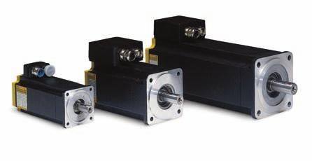
7 Baldor s Bushless Servo Motors provide low rotor inertia for high torque to inertia ratio in a very compact package. Designed for durability, high temperature, and ability to handle harsh environments in applications. Wide variety of models available from stock. Electrical windings - wide selection and wide voltage range - even up to 6 VDC Bus Permanent Magnet Rotor - durable, time proven, reliable design provides the highest torque to inertia ratio for rapid positioning capability Stator potted for environmental protection, current spike protection and high voltage protection Bearings with Exxon PolyRex EM polyurea grease proven to provide up to four times longer life and greater shear durability Typical BSM 9/1 shown BSM 5/63/8 Series use connectors.

8 Brushless Servo Motors BSM N-Series The BSM N-Series provides applications with low inertia to attain the highest acceleration capability - to position faster - to obtain the highest machine throughput. Baldor s motors are hard at work, increasing productivity, improving part quality, providing precision and reducing cost in many applications. This series provides continuous stall torques ranging from 3.9 lb-in (.4 N-m) to 354 lb-in (4 N-m). Peak torques are four times continuous. This series has the lowest inertia to provide the maximum torque per package size. > AC Servo Motors - N-Series Continuous Stall Torque Continuous Speed RPM Motor Motor Inertia Lb-In Nm Stall 32V 1 Number 2 Lb-In-S 2 Kg - cm BSM5N-133AX BSM5N-175AX BSM63N-133AX BSM63N-15AX BSM63N-175AX BSM5N-233AX BSM5N-275AX BSM5N-333AX BSM5N-375AX BSM63N-233AX BSM63N-25AX BSM63N-275AX BSM8N-133AX BSM8N-15AX BSM8N-175AX BSM63N-333AX BSM63N-35AX BSM63N-375AX BSM8N-233AX BSM8N-25AX BSM8N-275AX BSM8N-333AX BSM8N-35AX BSM8N-375AX BSM9N-175AX BSM9N-115AX BSM9N-125AX BSM9N-275AX BSM9N-215AX BSM9N-225AX BSM9N-375AX BSM9N-315AX BSM9N-325AX BSM1N-115AX BSM1N-125AX BSM1N-215AX BSM1N-225AX BSM1N-315AX BSM1N-325AX BSM1N-415AX BSM1N-425AX NOTE: 1 Nominal rpm shown at 32 VDC bus for convenience. For 64 VDC double the speed. Reference motor table to verify that max speed is not exceeded. 2 For X callout, see motor ID matrix.
 to 256 lb-in (3 N-m). Peak torques are typically three times continuous.")
9 BSM C-Series The BSM C-Series has as standard, a higher inertia - thus providing an excellent match for equipment requiring higher inertial matching for the machine. This series provides continuous stall capability ranging from 1 lb-in (1.2 N-m) to 256 lb-in (3 N-m). Peak torques are typically three times continuous. Baldor s BSM C-series provides 2%-5% more torque in a smaller size (2 inches/5 mm shorter) compared to previous Baldor models. The C-Series provides an economical package best used in applications with higher load inertias. > AC Servo Motors - C-Series Continuous Stall Torque Continuous Speed RPM Motor Motor Inertia Lb-In Nm Stall 32V 1 Number 2 Lb-In-S 2 Kg - cm BSM8C-15AX BSM8C-175AX BSM8C-25AX BSM8C-275AX BSM8C-215AX BSM9C-115AX BSM8C-35AX BSM8C-375AX BSM8C-315AX BSM8C-475AX BSM8C-415AX BSM1C-115AX BSM1C-125AX BSM9C-275AX BSM9C-215AX BSM9C-225AX BSM9C-375AX BSM9C-315AX BSM9C-325AX BSM1C-215AX BSM1C-225AX BSM1C-315AX BSM1C-325AX BSM1C-415AX BSM1C-425AX BSM1C-515AX BSM1C-525AX BSM1C-615AX BSM1C-625AX NOTE: 1 Nominal rpm shown at 32 VDC bus for convenience. For 64 VDC double the speed. Reference motor table to verify that max speed is not exceeded. 2 For X callouts, see motor ID matrix.

10 Brushless Servo Motors Brushless Servo Motors SSBSM-Series Baldor s totally stainless steel SSBSM series of motors are designed for food, liquid, hygiene or corrosive environments. These motors are designed to handle IP67 applications and withstand 15 psi washdown conditions. Included in this quality design are double sealed bearings and O-rings, environmental protected stator design with premium moisture resistant wire, and internal thermal over temperature protection. Baldor s SSBSM products are designed to be durable - they are BISSC, UL, cul and CE approved. > Stainless Steel Brushless Servo Motors Continuous Stall Torque Continuous Speed RPM Motor Catalog Motor Inertia Lb-In Nm Stall 32V Number Lb-In-S 2 Kg-cm 2 Standard Inertia Stainless Steel Brushless Servo Motors - SSBSM C-Series SSBSM8C-175CX SSBSM8C-275CX SSBSM8C-375CX SSBSM8C-475CX SSBSM9C-215CX SSBSM9C-315CX SSBSM1C-215CX SSBSM1C-315CX SSBSM1C-415CX SSBSM1C-515CX SSBSM1C-615CX Low Inertia Stainless Steel Brushless Servo Motors - SSBSM N-Series SSBSM5N-175CX SSBSM5N-275CX SSBSM5N-375CX SSBSM63N-275CX SSBSM63N-375CX SSBSM8N-275CX SSBSM8N-375CX SSBSM9N-115CX SSBSM9N-215CX SSBSM9N-315CX SSBSM1N-215CX SSBSM1N-315CX SSBSM1N-425CX NOTE: 1 Nominal rpm shown at 32 VDC bus for convenience. For 64 VDC double the speed. Reference motor table to verify that max speed is not exceeded. 2 Stainless steel connectors rated for 2 amps. 3 For X callout, see motor ID matrix.
11 Brushless Servo Motor Identification Matrix for N- and C- Series 11 B S * M Blank = Std SS = Stainless Steel* Frame* IEC NEMA 5 5N 63 6N 8 8N 9 9N 1 Series N C Motor Size Winding Code 5 75 etc. *Note: Not all options are available on all motors. Contact your local Baldor District Office. SSBSM motors available with IEC frame. Motor Options Description Standard (Metric) Threaded Style Connections Optional (Inch) Quick Connect Cables (5) Flying Leads (5) Motor (no shaft seal) A I E M Motor and brake B J F N Motor with shaft oil seal C K G O Motor with brake and shaft oil seal D L H P Feedback Options A = Resolver E = Encoder w/commutation (1 ppr) F = Encoder w/commutation (25 ppr) H = Halls only Y = Resolver mounting only V = Encoder mounting only D = Absolute Encoder Multi-turn (En Dat) S = SSI Encoder Single-turn S2 = SSI Encoder Multi-turn Accessory Options Blank = No Option M = No Keyway N = DIN R O = DIN R & No Keyway P = Optional Motor Connector on BSM 9 (Note: This option available only if current less than 2 amps) X = Special Option (order by spec no. only) Z1 = Blower (115 VAC) (not available on all motors) Z2 = Blower (23 VAC) (not available on all motors)) NOTE: 1) The standard BSM5/63/8 Series includes feedback, two threaded connector (metric style) for feedback and motor terminations, square mounting flange. 2) The standard BSM9/1 Series includes feedback, one threaded connector (metric style) for feedback, termination of motor lead wires on terminal block, square mounting flange. 3) Motors do not have shaft seal. 4) The standard BSM5 Series has as standard no keyway. 5) Shielded cables and flying leads are one meter long as standard. 6) SSBSM motors available with IEC mounting and include as standard a shaft seal 7) Contact Baldor for special options.
12 Brushless Servo Motors Speed Torque Curves How to Read Motor Performance Curves Baldor has provided the following curves in order to simplify the process of selecting both a motor and control for a specific application. The following paragraphs explain how the information in these curves should be interpreted. In constant speed applications, motors are defined in terms of horsepower or kilowatts (which is torque at a base speed). Servo motors normally operate over a wide speed range. The curves show continuous torque (defined as torque which will not overheat the motor), and peak torque (defined as intermittent acceleration torque). It is also necessary to know the current and voltage required for the motor to operate. The curves have a scale that shows current required for any torque, and voltage required for any speed. As an example, an application requires a continuous torque of 25 lb-in (2.8 Nm) at a speed of 1 RPM. The peak torque required for acceleration is 8 lb-in (9 Nm). Peak motor current Peak torque for the application Peak current required for the application Continuous torque for the application Continuous current required for the application VDC BUS 65 VDC BUS Continuous torque at speed for the application SPEED (rpm) x 1 Intermittent Operation Area Continuous Operation Area Required speed for the application Maximum motor speed This curve shows that the motor will work in this application. The bus voltage required is 32VDC. The continuous and peak currents required is 3.5 and 12 amps. Contact Baldor for special windings, custom shafts/mountings, and custom specs. Precision balancing for high speed applications can be provided.
13 How to Interpret Motor Information 13 Rated Voltage/Speed Rated conditions refer to measurement points, and are selected as an easy and convenient reference or measurement point. Manufacturers select a rated voltage, operate with a rated torque, to verify that rated speed is reached. Note that any voltage may be applied to Baldor motors. Thus, with the BSM series of brushless servo motors, either 16 VDC, 3 VDC, or 65 VDC may be applied. However the design limits must be observed. And those are: 1) maximum speed (rpm) limit, 2) demagnetization (max torque/current) limit, and 3) 65 VDC maximum. Motor Data All Baldor BSM motors are 3-phase WYE connected. Connection is important because the motor/feedback is phase sensitive. All motor parameters are expressed as phase to phase (line-to-line) figures. This includes voltage constant, resistance and inductance. The phase to phase voltage constant (back-emf) is a sinusoidal wave, which is measured while driving the motor (as a generator) at 1 rpm, and measuring the output voltage. The peak of this measured output voltage is shown in the literature as Vpk/krpm; the RMS of the output voltage is Vrms/krpm. Some data in the motor tables are expressed as cold figures (25 C), while others are hot (155 C) values. The cold figures are: voltage constant, torque constant, resistance, inductance. The hot figures are: continuous stall torque and all currents. The temperature coefficient between cold and hot voltage constant (and torque constant) is.9 for BSM and SSBSM series motors. Motor resistance changes by a factor of 1.5 from 25 C to 155 C. Motor Temperature The BSM series of servo motors are rated for a maximum continuous winding temperature of 155 C. This allows for a temperature rise of 13 C in a 25 C ambient. For operation at 4 C ambient derate by 6%. The temperature rise of the motor windings depends upon the amount of torque which is being delivered to the load. In this brochure, the thermal limit line (line dividing dark and light shaded areas on the speed-torque curves) indicates the 155 C limit (13 C temperature rise). Temperature range - normal operating range of bearing grease is - 29 C to 155 C. Altitude - the motors are rated for operation at 1m or lower; derate 1% per 1m. The BSM motors include an internal thermal switch (bi-metallic) which is normally closed. It opens at 155 C ±5. This switch may be connected to the input of a motion controller, programmable logic device, or other type of machine control. Any of these devices could then sense this switch and shut power down when the thermal switch opens.
14 Brushless Servo Motors Brushless Servo N-Series The BSM N Series provides the lowest inertia and high torque desired for excellent performance response. This series is a rugged, durable industrial design and construction with Neodymium Iron Boron magnetics. They are capable of peak torques equal to four times continuous to provide the highest acceleration torques in applications. Baldor BSM motors are available with a wide variety of feedback devices to suit application needs. IEC and NEMA configurations are available. Torque Range > BSM5 3.9 lb-in (.45Nm) - 12 lb-in (1.36Nm) > BSM lb-in (.7Nm) lb-in (2.8Nm) > BSM lb-in (1.6Nm) - 4 lb-in (4.5Nm) > BSM9 53 lb-in (6Nm) lb-in (13.3Nm) > BSM1 123 lb-in (14Nm) lb-in (4Nm) Variety of feedback options: > Resolver > Incremental/Absolute Encoders > Hall sensors > Synchronous Serial Interface (SSI) Popular shaft/mounting dimensions > Stock and custom > IEC and NEMA Precision wrapped rotor. High acceleration capability - to move faster, to get the job done faster. High torque to inertia ratio - enables your machine to produce more parts per hour. Proven reliable bearings. 4 times longer bearing life. Moisture/Dust resistant o-rings. Environmentally rugged - for reliability and long life. Optional shaft seal. High temperature operation. Over temperature protection thermal switch. Heavy duty continuous operation - for dependable performance. High voltage insulation. Windings potted for additional voltage protection - for improved reliability and improved heat transfer. Captured front bearing eliminates axial movement Cooling kits available on some models - to obtain more performance and extend torque range. Optional holding brakes available. Typical BSM63/8 series shown
15 BSM N-Series Performance Curves BSM5N-133 BSM5N-175 BSM5N BSM5N-133 BSM5N-175 BSM5N VDC BUS 32 VDC BUS VDC BUS 32 VDC BUS VDC BUS 32 VDC BUS SPEED (rpm) x SPEED (rpm) x SPEED (rpm) x 1 Model Number BSM5N-133 BSM5N-175 BSM5N-233 General Continuous Stall Torque lb-in N-m Continuous Stall Current amps Peak Torque lb-in N-m Peak Current amps Thermal Resistance C/watt Mechanical Time Constant msec Electrical Time Constant msec Rated volts rpm Rated volts rpm Electrical Torque Constant lb-in/amp N-m/amp Voltage Constant Vpk/krpm Vrms/krpm Resistance ohms Inductance mh Mechanical Inertia lb-in-s Kg-cm Maximum Speed rpm 1, 1, 1, Number of Motor Poles Weight lbs/kg 2.4/ / /1.6
16 Brushless Servo Motors BSM N-Series Performance Curves BSM5N-275 BSM5N-333 BSM5N-375 BSM5N-275 BSM5N-333 BSM5N VDC BUS 32 VDC BUS 65 VDC BUS VDC BUS 32 VDC BUS 65 VDC BUS VDC BUS 32 VDC BUS 6 7 SPEED (rpm) x SPEED (rpm) x SPEED (rpm) x 1 Model Number BSM5N-275 BSM5N-333 BSM5N-375 General Continuous Stall Torque lb-in N-m Continuous Current amps Peak Torque lb-in N-m Peak Current amps Thermal Resistance C/watt Mechanical Time Constant msec Electrical Time Constant msec Rated volts rpm Rated volts rpm Electrical Torque Constant lb-in/amp N-m/amp Voltage Constant Vpk/krpm Vrms/krpm Resistance ohms Inductance mh Mechanical Inertia lb-in-s Kg-cm Maximum Speed rpm 1, 1, 1, Number of Motor Poles Weight lbs/kg 3.4/ /2 4.4/2
17 BSM N-Series Performance Curves BSM63N-133 BSM63N-15 BSM63N BSM63N-133 BSM63N-15 BSM63N VDC BUS 32 VDC BUS VDC BUS 32 VDC BUS VDC BUS 16 VDC BUS 65 VDC BUS SPEED (rpm) x SPEED (rpm) x SPEED (rpm) x 1 Model Number BSM63N-133 BSM63N-15 BSM63N-175 General Continuous Stall Torque lb-in N-m Continuous Current amps Peak Torque lb-in N-m Peak Current amps Thermal Resistance C/watt Mechanical Time Constant msec Electrical Time Constant msec Rated volts rpm Rated volts rpm Electrical Torque Constant lb-in/amp N-m/amp Voltage Constant Vpk/krpm Vrms/krpm Resistance ohms Inductance mh Mechanical Inertia lb-in-s Kg-cm Maximum Speed rpm 1, 1, 1, Number of Motor Poles Weight lbs/kg 3.7/ / /1.68
18 Brushless Servo Motors BSM N-Series Performance Curves BSM63N-233 BSM63N-25 BSM63N-275 BSM63N-233 BSM63N-25 BSM63N VDC BUS 32 VDC BUS VDC BUS 32 VDC BUS VDC BUS 32 VDC BUS 65 VDC BUS 6 7 SPEED (rpm) x SPEED (rpm) x SPEED (rpm) x 1 Model Number BSM63N-233 BSM63N-25 BSM63N-275 General Continuous Stall Torque lb-in N-m Continuous Current amps Peak Torque lb-in N-m Peak Current amps Thermal Resistance C/watt Mechanical Time Constant msec Electrical Time Constant msec Rated volts rpm Rated volts rpm Electrical Torque Constant lb-in/amp N-m/amp Voltage Constant Vpk/krpm Vrms/krpm Resistance ohms Inductance mh Mechanical Inertia lb-in-s Kg-cm Maximum Speed rpm 1, 1, 1, Number of Motor Poles Weight lbs/kg 5/2.3 5/2.3 5/2.3
19 BSM N-Series Performance Curves BSM63N-333 BSM63N-35 BSM63N BSM63N-333 BSM63N-35 BSM63N VDC BUS 32 VDC BUS VDC BUS 32 VDC BUS VDC BUS 32 VDC BUS 65 VDC BUS SPEED (rpm) x SPEED (rpm) x SPEED (rpm) x 1 Model Number BSM63N-333 BSM63N-35 BSM63N-375 General Continuous Stall Torque lb-in N-m Continuous Current amps Peak Torque lb-in N-m Peak Current amps Thermal Resistance C/watt Mechanical Time Constant msec Electrical Time Constant msec Rated volts rpm Rated volts rpm Electrical Torque Constant lb-in/amp N-m/amp Voltage Constant Vpk/krpm Vrms/krpm Resistance ohms Inductance mh Mechanical Inertia lb-in-s Kg-cm Maximum Speed rpm 1, 1, 1, Number of Motor Poles Weight lbs/kg 6.3/ / /2.9
20 Brushless Servo Motors BSM N-Series Performance Curves BSM8N-133 BSM8N-15 BSM8N-175 BSM8N-133 BSM8N-15 BSM8N VDC BUS 32 VDC BUS VDC BUS 32 VDC BUS VDC BUS 32 VDC BUS SPEED (rpm) x SPEED (rpm) x 1 SPEED (rpm) x 1 Model Number BSM8N-133 BSM8N-15 BSM8N-175 General Continuous Stall Torque lb-in N-m Continuous Current amps Peak Torque lb-in N-m Peak Current amps Thermal Resistance C/watt Mechanical Time Constant msec Electrical Time Constant msec Rated volts rpm Rated volts rpm Electrical Torque Constant lb-in/amp N-m/amp Voltage Constant Vpk/krpm Vrms/krpm Resistance ohms Inductance mh Mechanical Inertia lb-in-s Kg-cm Maximum Speed rpm Number of Motor Poles Weight lbs/kg 7/3.2 7/3.2 7/3.2
21 32 VDC BUS BSM N-Series Performance Curves BSM8N-233 BSM8N-25 BSM8N BSM8N-233 BSM8N-25 BSM8N VDC BUS VDC BUS 32 VDC BUS VDC BUS 32 VDC BUS SPEED (rpm) x SPEED (rpm) x 1 SPEED (rpm) x 1 Model Number BSM8N-233 BSM8N-25 BSM8N-275 General Continuous Stall Torque lb-in N-m Continuous Current amps Peak Torque lb-in N-m Peak Current amps Thermal Resistance C/watt Mechanical Time Constant msec Electrical Time Constant msec Rated volts rpm Rated volts rpm Electrical Torque Constant lb-in/amp N-m/amp Voltage Constant Vpk/krpm Vrms/krpm Resistance ohms Inductance mh Mechanical Inertia lb-in-s Kg-cm Maximum Speed rpm Number of Motor Poles Weight lbs/kg 1/4.6 1/4.6 1/4.6
22 Brushless Servo Motors BSM N-Series Performance Curves BSM8N-333 BSM8N-35 BSM8N-375 BSM8N BSM8N VDC BUS VDC BUS VDC BUS 32 VDC BUS BSM8N VDC BUS 32 VDC BUS SPEED (rpm) x SPEED (rpm) x 1 SPEED (rpm) x 1 Model Number BSM8N-333 BSM8N-35 BSM8N-375 General Continuous Stall Torque lb-in N-m Continuous Current amps Peak Torque lb-in N-m Peak Current amps Thermal Resistance C/watt Mechanical Time Constant msec Electrical Time Constant msec Rated volts rpm Rated volts rpm Electrical Torque Constant lb-in/amp N-m/amp Voltage Constant Vpk/krpm Vrms/krpm Resistance ohms Inductance mh Mechanical Inertia lb-in-s Kg-cm Maximum Speed rpm Number of Motor Poles Weight lbs/kg 13/6 13/6 13/6
23 BSM N-Series Performance Curves BSM9N-175 BSM9N-115 BSM9N BSM9N BSM9N VDC BUS 32 VDC BUS VDC BUS 32 VDC BUS 65 VDC BUS BSM9N VDC BUS 32 VDC BUS 65 VDC BUS SPEED (rpm) x 1 SPEED (rpm) x SPEED (rpm) x 1 Model Number BSM9N-175 BSM9N-115 BSM9N-125 General Continuous Stall Torque lb-in N-m Continuous Current amps Peak Torque lb-in N-m Peak Current amps Thermal Resistance C/watt Mechanical Time Constant msec Electrical Time Constant msec Rated volts rpm Rated volts rpm Electrical Torque Constant lb-in/amp N-m/amp Voltage Constant Vpk/krpm Vrms/krpm Resistance ohms Inductance mh Mechanical Inertia lb-in-s Kg-cm Maximum Speed rpm Number of Motor Poles Weight lbs/kg 18/8.2 18/8.2 18/8.2
24 Brushless Servo Motors BSM N-Series Performance Curves BSM9N-275 BSM9N-215 BSM9N BSM9N VDC BUS 32 VDC BUS VDC BUS 32 VDC BUS 16 VDC BUS BSM9N VDC BUS 32 VDC BUS 16 VDC BUS BSM9N SPEED (rpm) x 1 SPEED (rpm) x SPEED (rpm) x 1 Model Number BSM9N BSM9N BSM9N General Continuous Stall Torque lb-in N-m Continuous Current amps Peak Torque lb-in N-m Peak Current amps Thermal Resistance C/watt Mechanical Time Constant msec Electrical Time Constant msec Rated volts rpm Rated volts rpm Electrical Torque Constant lb-in/amp N-m/amp Voltage Constant Vpk/krpm Vrms/krpm Resistance ohms Inductance mh Mechanical Inertia lb-in-s Kg-cm Maximum Speed rpm Number of Motor Poles Weight lbs/kg 28/ / / A blower cooling option is available which will increase the motor s continuous stall torque by another 8%.
25 BSM N-Series Performance Curves BSM9N-375 BSM9N-315 BSM9N BSM9N-375 BSM9N-315 BSM9N VDC BUS 32 VDC BUS VDC BUS 32 VDC BUS 65 VDC BUS VDC BUS 32 VDC BUS 65 VDC BUS SPEED (rpm) x 1 SPEED (rpm) x SPEED (rpm) x 1 Model Number BSM9N BSM9N BSM9N General Continuous Stall Torque lb-in N-m Continuous Current amps Peak Torque lb-in N-m Peak Current amps Thermal Resistance C/watt Mechanical Time Constant msec Electrical Time Constant msec Rated volts rpm Rated volts rpm Electrical Torque Constant lb-in/amp N-m/amp Voltage Constant Vpk/krpm Vrms/krpm Resistance ohms Inductance mh Mechanical Inertia lb-in-s Kg-cm Maximum Speed rpm Number of Motor Poles Weight lbs/kg 38/ / / A blower cooling option is available which will increase the motor s continuous stall torque by another 8%.
26 Brushless Servo Motors BSM N-Series Performance Curves BSM1N-115 BSM1N-125 BSM1N BSM1N VDC BUS 32 VDC BUS VDC BUS 32 VDC BUS 16 VDC BUS BSM1N BSM1N VDC BUS 32 VDC BUS SPEED (rpm) x SPEED (rpm) x SPEED (rpm) x 1 Model Number BSM1N-115 BSM1N-125 BSM1N-215 General Continuous Stall Torque lb-in N-m Continuous Current amps Peak Torque lb-in N-m Peak Current amps Thermal Resistance C/watt Mechanical Time Constant msec Electrical Time Constant msec Rated volts rpm Rated volts rpm Electrical Torque Constant lb-in/amp N-m/amp Voltage Constant Vpk/krpm Vrms/krpm Resistance ohms Inductance mh Mechanical Inertia lb-in-s Kg-cm Maximum Speed rpm Number of Motor Poles Weight lbs/kg 35/16 35/16 49/22.3
27 BSM N-Series Performance Curves BSM1N-225 BSM1N-315 BSM1N BSM1N-225 BSM1N-315 BSM1N VDC BUS 32 VDC BUS 65 VDC BUS VDC BUS 32 VDC BUS VDC BUS 32 VDC BUS 65 VDC BUS SPEED (rpm) x SPEED (rpm) x SPEED (rpm) x 1 Model Number BSM1N-225 BSM1N BSM1N General Continuous Stall Torque lb-in N-m Continuous Current amps Peak Torque lb-in N-m Peak Current amps Thermal Resistance C/watt Mechanical Time Constant msec Electrical Time Constant msec Rated volts rpm Rated volts rpm Electrical Torque Constant lb-in/amp N-m/amp Voltage Constant Vpk/krpm Vrms/krpm Resistance ohms Inductance mh Mechanical Inertia lb-in-s Kg-cm Maximum Speed rpm Number of Motor Poles Weight lbs/kg 49/ / / A blower cooling option is available which will increase the motor s continuous stall torque by another 6%.
28 Brushless Servo Motors BSM N-Series Performance Curves BSM1N-415 BSM1N-425 BSM1N-415 BSM1N VDC BUS 32 VDC BUS VDC BUS 32 VDC BUS 65 VDC BUS SPEED (rpm) x SPEED (rpm) x 1 Model Number BSM1N BSM1N General Continuous Stall Torque lb-in N-m 4. 4 Continuous Current amps Peak Torque lb-in N-m Peak Current amps Thermal Resistance C/watt Mechanical Time Constant msec Electrical Time Constant msec Rated volts rpm 2 12 Rated volts rpm 4 24 Electrical Torque Constant lb-in/amp N-m/amp Voltage Constant Vpk/krpm Vrms/krpm Resistance ohms Inductance mh Mechanical Inertia lb-in-s Kg-cm Maximum Speed rpm 4 4 Number of Motor Poles 8 8 Weight lbs/kg 77/35 77/35 1 A blower cooling option is available which will increase the motor s continuous stall torque by another 6%.

29 Brushless Servo C-Series 2 The BSM C Series of servo motors provide higher inertia in a very economical package. These motors have a reliable magnetic design, and are used in applications needing higher inertial matching. These rugged motors provide peak torques equal to three times continuous, thus enabling rapid acceleration for the higher inertial demanding applications. Besides a wide variety of feedback devices, other options such as brakes and cooling to extend performance, mounting, shaft and electrical windings are availlable for your application needs. Baldor also has stocked motors for immediate delivery for your application needs. Torque Range > BSM8 1 lb-in (1.2 Nm) - 38 lb-n (4.3Nm) > BSM9 23 lb-in (2.6Nm) - 69 lb-in (7.8Nm) > BSM1 44 lb-in (5Nm) lb-in (3Nm) Variety of feedback options: > Resolver > Incremental/Absolute Encoders > Hall sensors > Synchronous Serial Interface (SSI) Stock and custom shafts and mountings. Rugged industrial construction - quality in the design. > IEC and NEMA > Design interchangeable with N-Series - versatility for machine designs. High continuous rated operating temperature. Over temperature protective thermal switch. Proven reliable bearings. 4 times longer bearing life. O-rings for moisture and dust resistance. Rugged design for rugged environments - quality in the design. Higher rotor inertia - for matching heavier machine inertial loads. Optional forced air cooling on some models - to extend torque capability for additional motor performance. Typical BSM 9/1 series shown Optional holding brakes. High voltage insulation. Windings potted for additional voltage protection - for improved reliability and improved heat transfer. Optional shaft seal.
30 Brushless Servo Motors BSM C-Series Performance Curves BSM8C-15 BSM8C-175 BSM8C-25 BSM8C-15 BSM8C-175 BSM8C VDC BUS 32 VDC BUS VDC BUS 32 VDC BUS VDC BUS 32 VDC BUS SPEED (rpm) x 1 SPEED (rpm) x SPEED (rpm) x 1 Model Number BSM8C-15 BSM8C-175 BSM8C-25 General Continuous Stall Torque lb-in N-m Continuous Current amps Peak Torque lb-in N-m Peak Current amps Thermal Resistance C/watt Mechanical Time Constant msec Electrical Time Constant msec Rated volts rpm Rated volts rpm Electrical Torque Constant lb-in/amp N-m/amp Voltage Constant Vpk/krpm Vrms/krpm Resistance ohms Inductance mh Mechanical Inertia lb-in-s Kg-cm Maximum Speed rpm 1, 1, 1, Number of Motor Poles Weight lbs/kg 9/4.1 9/4.1 1/4.5
31 BSM8C-275 BSM8C-215 BSM8C BSM8C-275 BSM8C-215 BSM8C VDC BUS 32 VDC BUS VDC BUS 65 VDC BUS VDC BUS 32 VDC BUS SPEED (rpm) x 1 SPEED (rpm) x SPEED (rpm) x 1 Model Number BSM8C-275 BSM8C-215 BSM8C-35 General Continuous Stall Torque lb-in N-m Continuous Current amps Peak Torque lb-in N-m Peak Current amps Thermal Resistance C/watt Mechanical Time Constant msec Electrical Time Constant msec Rated volts rpm Rated volts rpm Electrical Torque Constant lb-in/amp N-m/amp Voltage Constant Vpk/krpm Vrms/krpm Resistance ohms Inductance mh Mechanical Inertia lb-in-s Kg-cm Maximum Speed rpm 1, 1, 1, Number of Motor Poles Weight lbs/kg 1/4.5 1/4.5 11/5.
32 Brushless Servo Motors BSM C-Series Performance Curves BSM8C-375 BSM8C-315 BSM8C-475 BSM8C VDC BUS 32 VDC BUS BSM8C-315 BSM8C VDC BUS 65 VDC BUS VDC BUS 32 VDC BUS SPEED (rpm) x SPEED (rpm) x 1 SPEED (rpm) x 1 Model Number BSM8C-375 BSM8C-315 BSM8C-475 General Continuous Stall Torque lb-in N-m Continuous Current amps Peak Torque lb-in N-m Peak Current amps Thermal Resistance C/watt Mechanical Time Constant msec Electrical Time Constant msec Rated volts rpm Rated volts rpm Electrical Torque Constant lb-in/amp N-m/amp Voltage Constant Vpk/krpm Vrms/krpm Resistance ohms Inductance mh Mechanical Inertia lb-in-s Kg-cm Maximum Speed rpm 1, 1, 1, Number of Motor Poles Weight lbs/kg 11/5. 11/5. 13/5.9
33 BSM C-Series Performance Curves BSM8C-415 BSM9C-115 BSM9C BSM8C-415 BSM9C-115 BSM9C VDC BUS 65 VDC BUS VDC BUS 65 VDC BUS VDC BUS 32 VDC BUS SPEED (rpm) x 1 SPEED (rpm) x 1 SPEED (rpm) x 1 Model Number BSM8C-415 BSM9C-115 BSM9C General Continuous Stall Torque lb-in N-m Continuous Current amps Peak Torque lb-in N-m Peak Current amps Thermal Resistance C/watt Mechanical Time Constant msec Electrical Time Constant msec Rated volts rpm Rated volts rpm Electrical Torque Constant lb-in/amp N-m/amp Voltage Constant Vpk/krpm Vrms/krpm Resistance ohms Inductance mh Mechanical Inertia lb-in-s Kg-cm Maximum Speed rpm 1, 1, 1, Number of Motor Poles 4 8 Weight lbs/kg 13/5.9 3/ / A blower cooling option is available which will increase the motor s continuous stall torque by another 8%.
34 Brushless Servo Motors BSM C-Series Performance Curves BSM9C-215 BSM9C-225 BSM9C-375 BSM9C-215 BSM9C-225 BSM9C VDC BUS 65 VDC BUS VDC BUS 65 VDC BUS VDC BUS 32 VDC BUS SPEED (rpm) x SPEED (rpm) x 1 SPEED (rpm) x 1 Model Number BSM9C BSM9C BSM9C General Continuous Stall Torque lb-in N-m Continuous Current amps Peak Torque lb-in N-m Peak Current amps Thermal Resistance C/watt Mechanical Time Constant msec Electrical Time Constant msec Rated volts rpm Rated volts rpm Electrical Torque Constant lb-in/amp N-m/amp Voltage Constant Vpk/krpm Vrms/krpm Resistance ohms Inductance mh Mechanical Inertia lb-in-s Kg-cm Maximum Speed rpm 1, 1, 1, Number of Motor Poles Weight lbs/kg 35/ /15.9 4/ A blower cooling option is available which will increase the motor s continuous stall torque by another 8%.
35 BSM C-Series Performance Curves BSM9C-315 BSM9C-325 BSM1C BSM9C-315 BSM9C-325 BSM1C VDC BUS 65 VDC BUS VDC BUS 65 VDC BUS VDC BUS 65 VDC BUS SPEED (rpm) x SPEED (rpm) x 1 SPEED (rpm) x 1 Model Number BSM9C BSM9C BSM1C-115 General Continuous Stall Torque lb-in N-m Continuous Current amps Peak Torque lb-in N-m Peak Current amps Thermal Resistance C/watt Mechanical Time Constant msec Electrical Time Constant msec Rated volts rpm Rated volts rpm Electrical Torque Constant lb-in/amp N-m/amp Voltage Constant Vpk/krpm Vrms/krpm Resistance ohms Inductance mh Mechanical Inertia lb-in-s Kg-cm Maximum Speed rpm 1, 1, 7 Number of Motor Poles Weight lbs/kg 4/18.2 4/18.2 3/ A blower cooling option is available which will increase the motor s continuous stall torque by another 8%.
36 Brushless Servo Motors BSM C-Series Performance Curves BSM1C-125 BSM1C-215 BSM1C BSM1C VDC BUS 65 VDC BUS BSM1C VDC BUS 65 VDC BUS BSM1C VDC BUS 65 VDC BUS SPEED (rpm) x SPEED (rpm) x SPEED (rpm) x 1 Model Number BSM1C-125 BSM1C-215 BSM1C-225 General Continuous Stall Torque lb-in N-m Continuous Current amps Peak Torque lb-in N-m Peak Current amps Thermal Resistance C/watt Mechanical Time Constant msec Electrical Time Constant msec Rated volts rpm Rated volts rpm Electrical Torque Constant lb-in/amp N-m/amp Voltage Constant Vpk/krpm Vrms/krpm Resistance ohms Inductance mh Mechanical Inertia lb-in-s Kg-cm Maximum Speed rpm Number of Motor Poles Weight lbs/kg 3/ / /17.7
37 BSM C-Series Performance Curves BSM1C-315 BSM1C BSM1C-315 BSM1C VDC BUS 65 VDC BUS VDC BUS 65 VDC BUS SPEED (rpm) x SPEED (rpm) x 1 Model Number BSM1C-315 BSM1C-325 General Continuous Stall Torque lb-in N-m Continuous Current amps Peak Torque lb-in N-m Peak Current amps Thermal Resistance C/watt.8.8 Mechanical Time Constant msec Electrical Time Constant msec Rated volts rpm Rated volts rpm Electrical Torque Constant lb-in/amp N-m/amp Voltage Constant Vpk/krpm Vrms/krpm Resistance ohms Inductance mh Mechanical Inertia lb-in-s Kg-cm Maximum Speed rpm 7 7 Number of Motor Poles 8 8 Weight lbs/kg 5/22.7 5/22.7
38 Brushless Servo Motors BSM C-Series Performance Curves BSM1C-415 BSM1C-425 BSM1C BSM1C VDC BUS 65 VDC BUS BSM1C VDC BUS 65 VDC BUS BSM1C VDC BUS 65 VDC BUS 6 7 SPEED (rpm) x SPEED (rpm) x 1 SPEED (rpm) x 1 Model Number BSM1C-415 BSM1C-425 BSM1C General Continuous Stall Torque lb-in N-m Continuous Current amps Peak Torque lb-in N-m Peak Current amps Thermal Resistance C/watt Mechanical Time Constant msec Electrical Time Constant msec Rated 3 volts rpm Rated volts rpm Electrical Torque Constant lb-in/amp N-m/amp Voltage Constant Vpk/krpm Vrms/krpm Resistance ohms Inductance mh Mechanical Inertia lb-in-s Kg-cm Maximum Speed rpm Number of Motor Poles Weight lbs/kg 59/ /26.8 7/ A blower cooling option is available which will increase the motor s continuous stall torque by another 6%.
39 BSM C-Series Performance Curves BSM1C-525 BSM1C-615 BSM1C BSM1C VDC BUS 65 VDC BUS BSM1C VDC BUS 65 VDC BUS BSM1C VDC BUS 65 VDC BUS SPEED (rpm) x 1 SPEED (rpm) x SPEED (rpm) x 1 Model Number BSM1C BSM1C BSM1C General Continuous Stall Torque lb-in N-m Continuous Current amps Peak Torque lb-in N-m Peak Current amps Thermal Resistance C/watt Mechanical Time Constant msec Electrical Time Constant msec Rated 3 volts rpm Rated volts rpm Electrical Torque Constant lb-in/amp N-m/amp Voltage Constant Vpk/krpm Vrms/krpm Resistance ohms Inductance mh Mechanical Inertia lb-in-s Kg-cm Maximum Speed rpm Number of Motor Poles Weight lbs/kg 7/ / / A blower cooling option is available which will increase the motor s continuous stall torque by another 6%.
40 Brushless Servo Motors Brushless Servo Motors BSM Series Dimensions - IEC Mountings BSM5 Series BSM63/8 Series BSM9/1 Series Liquid Tight Strain Relief 1 (M25) AB BALDOR CSA AK U BB AJ L AH P Note: M25 Strain Relief is used on all BSM9/1 Series rated for 2 amps. Motors rated for greater than 2 amps should use M4 strain relief (P/N MCS-M4) and M4/M25 adaptor (P/N MCS-M4A). Shipped with cable assembly.
41 BSM Series Dimensions - IEC Mountings continued Dimensions in mm (inch) Motor Code P AB U AH Key AJ AK BB BSM5N 55 (2.17) 67 (2.64) 9j6 (.35) 2 (.78) None BSM63N 67 (2.6) 65 (2.6) 11j6 (.43) 23 (.9) 4x4x12 BSM8N/C 89 (3.5) 76 (3.) 19j6 (.74) 4 (1.5) 6x6x25 BSM9N/C 12 (4.7) 19 (4.3) 24j6 (.94) 5 (2.) 8x7x36 BSM1N/C 146 (5.7) 122 (4.8) 28j6 (1.1) 6 (2.3) 8x7x5 4.5mm thru hole 63mm B.C. 5.8mm thru hole 75mm B.C. 7.mm thru hole 1mm B.C. 1mm thru hole 13mm B.C. 12mm thru hole 165mm B.C. 4j6 (1.5) 2.5 (.98) 6j6 (2.3) 2.5 (.98) 8j6 (3.1) 3. (.118) 11j6 (4.3) 3.5 (.138) 13j6 (5.1) 3.5 (.138) 41 Length - L Length - L Motor Code Resolver Encoder Motor Code Resolver Encoder BSM5N (4.) (5.7) BSM8C BSM5N (5.) (6.7) BSM8C BSM5N (6.) (7.7) BSM8C BSM63N (4.56) (4.96) BSM8C BSM63N (5.56) (5.96) BSM9C (6.49) (6.49) BSM63N (6.56) (6.96) BSM9C (7.99) 22.8 (7.99) BSM8N (5.93) 15.7 (5.93) BSM9C (9.49) 24.9 (9.49) BSM8N (7.18) (7.18) BSM1C (6.49) (6.49) BSM8N (8.43) (8.43) BSM1C (7.99) 22.8 (7.99) BSM9N (6.99) (6.99) BSM1C (9.49) 24.9 (9.49) BSM9N (8.99) (8.99) BSM1C (1.99) 279. (1.99) BSM9N (1.99) 279. (1.99) BSM1C (12.49) (12.49) BSM1N (8.2) 23.1 (8.2) BSM1C (13.99) (13.99) BSM1N (1.) (1.) BSM1N (12.) 34.7 (12.) BSM1N (14.) (14.) Note: Standard configuration: All motors supplied with feedback device. Square mounting flange. BSM 5/63/8 has two (2) threaded connectors for resolver and motor terminations. BSM 9/1 has one (1) threaded connector for resolver, termination of motor lead wires on terminal block. Order mating cable assemblies/connectors as separate items. The motors have a threaded hole on the shaft end. The BSM63 series is M4 x.7 threads (11mm deep). The BSM8 series is M6 x 1. threads (17 mm deep). The BSM9 series is M6 x 1. threads (17 mm deep). The BSM1 series is M1 x 1.5 threads (23 mm deep). Dimensions are for reference only and may change for other selected option. Detailed engineering drawings are available upon request. Contact Baldor for dimensions with other feedback devices.
42 CAT SPEC MFG TORQ CONT. STALL CURR CONT. STALL POWER BRUSHLESS AC SERVOMOTOR RATED SPEED RATED BUS VOLTAGE PEAK CURRENT MAX SPEED CLASS MFD BY BALDOR ELECTRIC CO. A RMS RPM VOLTS A RMS RPM ºC AMB NPD766 FT SMITH, AR U.S.A. Brushless Servo Motors BSM Series Dimensions - NEMA Mountings BSM5 Series NEMA [59.9].17 [2.71].75 [1.9] Optional NEMA23 Mounting.85 [21.6].78 [19.8] AD S BALDOR CSA N D M LB BSM63/8 Series NEMA 34/42 T E + R BD Note Breakout.25 [6.35].2495 [6.336] 1.52 [38.15] [38.5] 4X Dia..215[5.46].195[4.95] Dia. 3.21(81.5) Thru (on a [66.67] Dia. B.C.) T E + R POWER CONN. BD FEEDBACK CONN. AD D N S BSM9 Series NEMA 56 LB M S NEMA Key Configuration.1875 (4.7) 1.5 (38) L Nominal Length Note: Dimensions shown for BSM8NN and 9NN (NEMA 42 & 56). BSM5NN and 6NN have as standard, no keyway (4.7)
43 Brushless Servo Motor Dimensions - NEMA Mountings Dimensions in mm (inch) NEMA Code Motor Code BD AD D E + R M S thru hole 23 BSM5NN 2.2 (55) 2.64 (67).25 (6.3).812 (2) B.C..2 in 1.5 (38).1 (2.5) 34 BSM6NN 3.14 (8) 2.88 (73).43 (11).9 (22) B.C..22 in (73).1 (2.5) 42 BSM8NN 4. (11) 3. (76).625 (15) 2. (52) 4.95 B.C..28 in (55).1 (2.5) 56 BSM9NN 5.17 (131) 4.3 (18).625 (15) 2. (52) B.C..4 in 4.5 (114).1 (2.5) 42 BSM8NC 4. (11) 3. (76).625 (15) 2. (52) 4.95 B.C..28 in (55).1 (2.5) 56 BSM9NC 5.17 (131) 4.3 (18).625 (15) 2. (52) B.C..4 in 4.5 (114).13 (3.3) N T 43 NEMA Code Length - LB Length - LB Motor Code Resolver Encoder Motor Code Resolver Encoder BSM5NN-1 4. (11.7) 5.7 (128.7) BSM5NN-2 5. (127.1) 6.7 (154.1) BSM5NN-3 6. (152.5) 7.7 ( BSM6NN (115.8) 5.33 (135.5) BSM6NN (141.2) 5.96 (151.3) BSM6NN (166.6) 6.96 (176.7) BSM8NN (151.3) 5.96 (151.3) BSM8NC (144.) 5.69 (144.6) BSM8NN (183.) 7.21 (183.) BSM8NC (169.) 6.69 (17.) BSM8NN (214.8) 8.46 (214.8) BSM8NC (194.8) 7.69 (195.4) BSM9NN (177.4) 6.99 (177.4) BSM8NC (22.2) 8.69 (22.8) BSM9NN (228.2) 8.99 (228.2) BSM9NC (164.7) 6.49 (164.7) BSM9NN (279.) 1.99 (279.) BSM9NC (22.8) 7.99 (22.8) BSM9NC (24.9) 9.49 (24.9 Note: Standard configuration: All motors are supplied with feedback device, NEMA mounting. BSM 5/63/8 has two (2) threaded connectors for resolver and motor terminations. BSM 9 has one (1) threaded connector for resolver, termination of motor lead wires on terminal block. Order mating cable assemblies/connectors as separate items. Dimensions are for reference only. Detailed engineering drawings are available upon request. Contact Baldor for dimension with other feedback devices. Motor identification/optional specifying information MUST include the code of N" designating NEMA dimensions, i.e. BSM8NN-XXX". Contact Baldor for other shaft dimensions.
44 Brushless Servo Motors BSM Series Dimensions - Blower cooling options BSM9 Series L BALDOR CSA BSM1 Series P L BALDOR CSA P BSM Series Dimensions - Blower cooling options Dimensions in mm (inch) Motor Code P L Blower Kit for Motor Blower Kit for Motor/Brake 115 VAC 23 VAC 115 VAC 23 VAC BSM9C/N (6.91) 381 (15) BSM9FN2-1 BSM9FN2-2 BSM9FN3-1 BSM9FN3-2 BSM9C/N (6.91) 433 (17) BSM9FN3-1 BSM9FN3-2 BSM9FN4-1 BSM9FN4-2 BSM1C/N (6.91) 453 (17.8) BSM1FN3-1 BSM1FN3-2 BSM1FN5-1 BSM1FN5-6 BSM1C/N (6.91) 54 (19.8) BSM1FN4-1 BSM1FN4-2 BSM1FN6-1 BSM1FN6-2 BSM1C (6.91) (18.4) BSM1FN4-1 BSM1FN4-2 BSM1FN6-1 BSM1FN6-2 BSM1C (6.91) 55.4 (19.9) BSM1FN4-1 BSM1FN4-2 BSM1FN6-1 BSM1FN6-2 Note: All blowers are single phase. Configuration shown is for resolver feedback. Dimensions are for reference only. Detailed engineering drawings available upon request. Order blower separately
 washdown conditions. Offered in standard and low inertia designs for best machine inertial matching.")
45 Stainless Steel Brushless Servo 45 Baldor s totally stainless steel SSBSM series of motors are designed for food, liquid, washdown, hygiene and harsh, corrosive environments. These motors are designed to handle IP67 and withstand 15 psi (13 bar) washdown conditions. Offered in standard and low inertia designs for best machine inertial matching. Included in this quality design are Teflon stainless steel double-sealed bearings with Viton O-rings, environmental protected stator with premium moisture resistant wire, and internal thermal over temperature protection. Baldor s SSBSM products are designed to be durable - they are BISSC, UL, cul and CE approved. Torque Range Low Inertia Models > SSBSM5 3.9 lb-in (.45Nm) - 12 lb-in (1.3Nm) > SSBSM63 13 lb-in (1.4Nm) lb-in (2Nm) > SSBSM8 23 lb-in (2.5Nm) - 32 lb-in (3.6Nm) > SSBSM9 42 lb-in (4.8Nm) - 94 lb-in (1Nm) > SSBSM1 163 lb-in (18Nm) lb-in (32Nm) Torque Range Standard Inertia Models > SSBSM8 8 lb-in (.9Nm) - 3 lb-in (3.4Nm) > SSBSM9 37 lb-in (4.2Nm) - 55 lb-in (6.2Nm) > SSBSM1 71 lb-in (8Nm) lb-in (24Nm) BISSC/UL/CSA/CE - Agency approvals - proven design, proven quality, proven reliability. Internal Thermal protection - to supply you with safeguards against overheating and overload conditions. Construction - All stainless steel prvides protection in harsh environments and washdown conditions - 34 housing, 416 shaft Laser etched nameplate - easy to clean - protects against contamination Motor housing - Durable design to handle IP67 and harsh 15 psi (13 bar) washdown conditions. Feedback - Variety available: resolver, encoder, absolute encoder - choices for your application. Stator - Reliable potted design provides environmental protection, high current spike protection and high voltage protection. Armature - proven quality design - to supply superior performance for your application. Wire - Premium 2 C moisture resistant, multi-coated copper wire - to improve your reliability Magnets - High energy - provides very high resistance to demagnetization, so the motor always performs. Insulation - UL rated for 13 C rise, and potted - to provide you with extra high insulation/safety Grease - Exxon Polyrex EX Polyurea - proven to provide 4 times greater life - H1 bearing grease for incendental food contact. FDA approved shaft seal Bearings - Quality grade ball bearings - to provide you with dependability and long trouble free life. Stock and custom designs available. Optional holding brakes. available. Typical BSM63/8 Series shown.
46 Brushless Servo Motors SSBSM Stainless Series Performance Curves SSBSM8C-175 SSBSM8C-275 SSBSM8C-375 SSBSM8C-175 SSBSM8C-275 SSBSM8C VDC BUS 32 VDC BUS VDC BUS 32 VDC BUS VDC BUS 32 VDC BUS SPEED (rpm) x 1 SPEED (rpm) x 1 SPEED (rpm) x 1 Model Number SSBSM8C-175 SSBSM8C-275 SSBSM8C-375 General Continuous Stall Torque lb-in N-m Continuous Current amps Peak Torque lb-in N-m Peak Current amps Thermal Resistance C/watt Mechanical Time Constant msec Electrical Time Constant msec Rated 3 volts rpm Rated 6 volts rpm Electrical Torque Constant lb-in/amp N-m/amp Voltage Constant Vpk/krpm Vrms/krpm Resistance ohms Inductance mh Mechanical Inertia lb-in-s Kg-cm Maximum Speed rpm 1, 1, 1, Number of Motor Poles Weight lbs/kg 12/5.5 15/6.8 18/8.2
47 SSBSM Stainless Series Performance Curves SSBSM8C-475 SSBSM9C-215 SSBSM9C SSBSM8C VDC BUS 32 VDC BUS SSBSM9C-215 SSBSM9C VDC BUS VDC BUS VDC BUS 65 VDC BUS SPEED (rpm) x 1 SPEED (rpm) x 1 SPEED (rpm) x 1 Model Number SSBSM8C-475 SSBSM9C-215 SSBSM9C-315 General Continuous Stall Torque lb-in N-m Continuous Current amps Peak Torque lb-in N-m Peak Current amps Thermal Resistance C/watt Mechanical Time Constant msec Electrical Time Constant msec Rated 3 volts rpm Rated 6 volts rpm Electrical Torque Constant lb-in/amp N-m/amp Voltage Constant Vpk/krpm Vrms/krpm Resistance ohms Inductance mh Mechanical Inertia lb-in-s Kg-cm Maximum Speed rpm 1, 7 7 Number of Motor Poles Weight lbs/kg 21/ / /11.8
48 Brushless Servo Motors SSBSM Stainless Series Performance Curves SSBSM1C-215 SSBSM1C-315 SSBSM1C-415 SSBSM1C-215 SSBSM1C-315 SSBSM1C VDC BUS VDC BUS VDC BUS VDC BUS VDC BUS 65 VDC BUS 6 SPEED (rpm) x 1 SPEED (rpm) x 1 SPEED (rpm) x 1 Model Number SSBSM1C-215 SSBSM1C-315 SSBSM1C-415 General Continuous Stall Torque lb-in N-m Continuous Current amps Peak Torque lb-in N-m Peak Current amps Thermal Resistance C/watt Mechanical Time Constant msec Electrical Time Constant msec Rated 3 volts rpm Rated 6 volts rpm Electrical Torque Constant lb-in/amp N-m/amp Voltage Constant Vpk/krpm Vrms/krpm Resistance ohms Inductance mh Mechanical Inertia lb-in-s Kg-cm Maximum Speed rpm Number of Motor Poles Weight lbs/kg 44.5/ / /26.6
49 SSBSM Stainless Series Performance Curves SSBSM1C-515 SSBSM1C-615 SSBSM5N SSBSM1C VDC BUS 65 VDC BUS SSBSM1C VDC BUS 65 VDC BUS SSBSM5N VDC BUS 32 VDC BUS SPEED (rpm) x 1 SPEED (rpm) x SPEED (rpm) x 1 Model Number SSBSM1C-515 SSBSM1C-615 SSBSM5N-175 General Continuous Stall Torque lb-in N-m Continuous Current amps Peak Torque lb-in N-m Peak Current amps Thermal Resistance C/watt Mechanical Time Constant msec Electrical Time Constant msec Rated 3 volts rpm Rated 6 volts rpm Electrical Torque Constant lb-in/amp N-m/amp Voltage Constant Vpk/krpm Vrms/krpm Resistance ohms Inductance mh Mechanical Inertia lb-in-s Kg-cm Maximum Speed rpm 7 7 1, Number of Motor Poles Weight lbs/kg 65.5/ /32.9 5/2.3
50 Brushless Servo Motors SSBSM Stainless Series Performance Curves SSBSM5N-275 SSBSM5N-375 SSBSM63N-275 SSBSM5N-275 SSBSM5N-375 SSBSM63N VDC BUS VDC BUS 32 VDC BUS 65 VDC BUS VDC BUS 32 VDC BUS VDC BUS 32 VDC BUS 65 VDC BUS 6 7 SPEED (rpm) x SPEED (rpm) x SPEED (rpm) x 1 Model Number SSBSM5N-275 SSBSM5N-375 SSBSM63N-275 General Continuous Stall Torque lb-in N-m Continuous Current amps Peak Torque lb-in N-m Peak Current amps Thermal Resistance C/watt Mechanical Time Constant msec Electrical Time Constant msec Rated 3 volts rpm Rated 16 volts rpm Electrical Torque Constant lb-in/amp N-m/amp Voltage Constant Vpk/krpm Vrms/krpm Resistance ohms Inductance mh Mechanical Inertia lb-in-s Kg-cm Maximum Speed rpm 1, 1, 1, Number of Motor Poles Weight lbs/kg 5.75/ /2.9 8/3.6
51 SSBSM Stainless Series Performance Curves SSBSM63N-375 SSBSM8N-275 SSBSM8N SSBSM63N VDC BUS 32 VDC BUS 65 VDC BUS SSBSM8N VDC BUS 32 VDC BUS SSBSM8N VDC BUS 32 VDC BUS SPEED (rpm) x 1 SPEED (rpm) x 1 SPEED (rpm) x 1 Model Number SSBSM63N-375 SSBSM8N-275 SSBSM8N-375 General Continuous Stall Torque lb-in N-m Continuous Current amps Peak Torque lb-in N-m Peak Current amps Thermal Resistance C/watt Mechanical Time Constant msec Electrical Time Constant msec Rated 3 volts rpm Rated 16 volts rpm Electrical Torque Constant lb-in/amp N-m/amp Voltage Constant Vpk/krpm Vrms/krpm Resistance ohms Inductance mh Mechanical Inertia lb-in-s Kg-cm Maximum Speed rpm 1, 7 7 Number of Motor Poles Weight lbs/kg 9/4 15.5/7 18.5/8.4
52 Brushless Servo Motors SSBSM Stainless Series Performance Curves SSBSM9N-115 SSBSM9N-215 SSBSM9N VDC BUS 32 VDC BUS 16 VDC BUS BSM9N SSBSM9N VDC BUS 32 VDC BUS 65 VDC BUS SSBSM9N VDC BUS 32 VDC BUS 65 VDC BUS SPEED (rpm) x 1 SPEED (rpm) x 1 SPEED (rpm) x 1 Model Number SSBSM9N-115 SSBSM9N-215 SSBSM9N-315 General Continuous Stall Torque lb-in N-m Continuous Current amps Peak Torque lb-in N-m Peak Current amps Thermal Resistance C/watt Mechanical Time Constant msec Electrical Time Constant msec Rated 3 volts rpm Rated 6 volts rpm Electrical Torque Constant lb-in/amp N-m/amp Voltage Constant Vpk/krpm Vrms/krpm Resistance ohms Inductance mh Mechanical Inertia lb-in-s Kg-cm Maximum Speed rpm Number of Motor Poles Weight lbs/kg 23.5/ / /12.5
53 SSBSM Stainless Series Performance Curves SSBSM1N-215 SSBSM1N-315 SSBSM1N SSBSM1N-215 SSBSM1N-315 SSBSM1N VDC BUS 32 VDC BUS VDC BUS 32 VDC BUS VDC BUS 32 VDC BUS 65 VDC BUS SPEED (rpm) x SPEED (rpm) x SPEED (rpm) x 1 Model Number SSBSM1N-215 SSBSM1N-315 SSBSM1N-425 General Continuous Stall Torque lb-in N-m Continuous Current amps Peak Torque lb-in N-m Peak Current amps Thermal Resistance C/watt Mechanical Time Constant msec Electrical Time Constant msec Rated 3 volts rpm Rated 6 volts rpm Electrical Torque Constant lb-in/amp N-m/amp Voltage Constant Vpk/krpm Vrms/krpm Resistance ohms Inductance mh Mechanical Inertia lb-in-s Kg-cm Maximum Speed rpm Number of Motor Poles Weight lbs/kg 59/ /37.7
54 CAT STAINLESS STEEL BRUSHLESS AC SERVOMOTOR SPEC MFG TORQ CONT. STALL CURR CONT. STALL POWER RATED SPEED RATED BUS VOLTAGE PEAK CURRENT MAX SPEED CLASS MFD BY BALDOR ELECTRIC CO. A RMS RPM VOLTS A RMS RPM ºC AMB FT SMITH, AR U.S.A. Brushless Servo Motors Stainless Steel Brushless Servo Motors SSBSM Series Dimensions - IEC Mountings SSBSM5/63/8 Series 33 (1.3) L BB AH P AK U AJ SSBSM9/1 Series L 33 (1.3) BB AH Stainless Key P AK U AJ
55 BSM Series Dimensions - IEC Mountings continued Dimensions in mm (inch) Motor Code P U AH Key AJ AK BB 55 SSBSM5N 57 (2.25) 9 (.35) 2 (.78) NONE SSBSM63N 69 (2.72) 11 (.43) 23 (.9) 4x4x12 SSBSM8C/N 91.3 (3.59) 19 (.74) 4 (1.5) 6x6x25 SSBSM9C/N (4.79) 24 (.94) 5 (2.) 8x7x36 SSBSM1C/N 148 (5.83) 28 (1.1) 6 (2.3) 8x7x mm thru hole 63 mm B.C. 5.8 mm thru hole 75 mm B.C. 7. mm thru hole 1 mm B.C. 1 mm thru hole 13 mm B.C. 12 mm thru hole 165 mm B.C. 4 (1.5) 2.5 (.98) 6 (2.3) 2.5 (.98) 8 (3.1) 3. (.118) 11 (4.3) 3.5 (.138) 13 (5.1) 3.5 (.138) Length - L Length - L Motor Code Resolver Encoder Motor Code Resolver Encoder SSBSM5N (5.8) (5.8) SSBSM8C (6.15) (6.15) SSBSM5N (6.8) (6.8) SSBSM8C (7.15) (7.15) SSBSM5N (7.8) (7.8) SSBSM8C (8.15) 27. (8.15) SSBSM63N (7.12) 18.9 (7.12) SSBSM8C (9.15) (9.15) SSBSM63N (8.12) 26.3 (8.12) SSBSM9C (8.96) (8.96) SSBSM8N (7.65) (7.65) SSBSM9C (1.46) (1.46) SSBSM8N (8.9) (8.9) SSBSM1C (9.6) 23.1 (9.6) SSBSM9N (7.96) 22.3 (7.96) SSBSM1C (1.56) (1.56) SSBSM9N (9.96) (9.96) SSBSM1C (12.6) 36.3 (12.6) SSBSM9N (11.96) 33.9 (11.96) SSBSM1C (13.56) (13.56) SSBSM1N (11.6) 28.9 (11.6) SSBSM1C (15.6) (15.6) SSBSM1N (13.6) (13.6) SSBSM1N (15.6) (15.6) Note: Standard configuration: All motors supplied with feedback device. Square mounting flange. SSBSM 5/63/8 has two (2) threaded connectors for feedback and motor terminations. Order mating cable assemblies/connectors as separate items. The motors have a threaded hole on the shaft end. The SSBSM63 series is M4 x.7 threads (11mm deep). The SSBSM8 series is M6 x 1. threads (17 mm deep). The SSBSM9 series is M6 x 1. threads (17 mm deep). The SSBSM1 series is M1 x 1.5 threads (23 mm deep). Dimensions are for reference only and may change for other selected option. Detailed engineering drawings are available upon request. Contact Baldor for dimensions with other feedback devices.

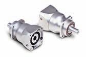
56 Brushless Servo Motors Precision Gearheads Designed specifically for BSM Servo Motors Planetary gearheads designed for servo applications requiring precision, durability and long trouble free operation. These are high efficiency gearheads to maximize the power transmission capability. Designed with low backlash to reduce shock loads in dynamic reversing applications. They mount directly to Baldor s BSM servo motor family to provide torque multiplication, speed reduction and inertia matching. > Standard servo rated gearheads > Stainless steel gearheads > Standard and lower backlash available > Right angle gearheads available > High efficiency Page58 MRP-Series MRP - Series Standard 1 to 15 arc-min backlash Page64 MNT-Series MNT - Series higher torque 6-15 arc-min backlash


57 5 Page7 MRA-Series MRA - Series right angle servo gearheads Page76 MSS-Series MSS - Series stainless steel servo rated gearheads

58 Brushless Servo Motors Standard Servo Rated Gearheads - MRP Series These planetary gearheads provide a standard backlash of 15-1 arc min and are designed for mounting directly on to Baldor s BSM servo motors. These efficient gearheads will maximize power transmission capability in applications. Standard Gearhead > Standard backlash is 15 to 1 arc-min max > Round face with tapped holes > Integrated, self-locaing input pinion clamps onto motor shaft > Lubrication - grease - 15 K hours > Satellite gear shaft is cantilever supported in carrier (needle bearings) > Satellite gear teeth - deep case hardened and finish ground > Medium to high torque/size & torsional stiffness > Gearhead housing - aluminum input module, steel output module
59 Quick Selection Guide for Standard MRP Servo Rated Gearheads 1 to 15 arc min backlash MOTOR BSM Series SELECTION CHART FOR BSM C-SERIES AND STANDARD GEARHEADS (MRP) 1 Stage Ratios 2 Stage Ratios C 1XX C 2XX * 8C 3XX * 8C 4XX * * 59 9C 1XX * 9C 2XX * * 9C 3XX * * * * 1C 1XXX * * 1C 2XXX * * * * * 1C 3XXX * * * * * * 1C 4XXX * * * * * * * * * 1C 5XXX * * * * * * * * * * 1C 6XXX * * * * * * * * * * Ordering nonmenclature: for Gearhead only G BSM8 - MRP9-4 Gear Motor Gearhead type Ratio MOTOR BSM Series SELECTION CHART FOR BSM N-SERIES AND STANDARD GEARHEADS (MRP) 1 Stage Ratios 2 Stage Ratios N 1XX * 5N 2XX * * 5N 3XX * * * 63N 1XX N 2XX * 63N 3XX * 8N 1XX N 2XX * 8N 3XX * * 9N 1XX * * 9N 2XX * * * * * 9N 3XX * * * * * 1N 1XXX * * * * * * 1N 2XXX * * * * * * * * * 1N 3XXX * * * * * * * * * 1N 4XXX * * * * * * * * * * Ordering nonmenclature: for Gearhead only G BSM5 - MRP5-1 Gear Motor Gearhead type Ratio Also Refer to Quick Selection in engineering information section.
60 Brushless Servo Motors Characteristics of Standard Planetary Gearheads MRP 5 No of Stages 1 - Stage 2 - Stages Ratio INPUT Rated speed / Max. rpm Power T1 & N1 rated Kw Rated torque (T1) Lb-in Nm Lb-in Accel torque (1) Nm OUTPUT Rated speed rpm Rated torque (T2) Lb-in Nm Lb-in Accel torque (1) Nm GENERAL DATA Inertia (2) Lb-in-s 2 x Kg-m 2 x Max. Backlash arc-mins Efficiency % (3) Rated Life H 15, Weight Kg / Lbf.9/2 1.2/2.7 Radial Load (4) N / Lbf 7/157 Axial Load N / Lbf 7/157 MRP 7 No of Stages 1 - Stage 2 - Stages Ratio INPUT Rated speed / Max. rpm 4 / 6 Power T1 & N1 rated Kw Rated torque (T1) Lb-in Nm Lb-in Accel torque (1) Nm OUTPUT Rated speed rpm Rated torque (T2) Lb-in Nm Lb-in Accel torque (1) Nm GENERAL DATA Inertia (2) Lb-in-s 2 x Kg-m 2 x Max. Backlash arc-mins Efficiency (3) % Rated Life H 15, Weight Kg / Lbf 1.5/3.3 2/4.4 Radial Load (4) N / Lbf 15/337 Axial Load N / Lbf 15/337 Note: (1) S5 duty service. (2) On the motorside. (3) Theoretical gear efficiency value. (4) Load applied in the middle of the output shaft at 3 rpm. (5) Emergency Stop Torque is 2.5 times Rated Output Torque for 1 times max during the service life of the gearhead.
61 Characteristics of Standard Planetary Gearheads MRP 9 No of Stages 1 - Stage 2 - Stages Ratio INPUT Rated speed / Max. rpm 4 / 6 Power T1 & N1 rated Kw Rated torque (T1) Lb-in Nm Lb-in Accel torque (1) Nm OUTPUT Rated speed rpm Rated torque (T2) Lb-in Nm Lb-in Accel torque (1) Nm GENERAL DATA 61 Inertia (2) Lb-in-s 2 x Kg-m 2 x Max. Backlash arc-mins 1 12 Efficiency (3) % Rated Life H 15, Weight Kg / Lbf 3/6.6 4/8.8 Radial Load (4) N / Lbf 25/562 Axial Load N / Lbf 2/45 MRP 12 No of Stages 1 - Stage 2 - Stages Ratio INPUT Rated speed / Max. rpm 4 / 6 Power T1 & N1 rated Kw Rated torque (T1) Lb-in Nm Lb-in Accel torque (1) Nm OUTPUT Rated speed rpm Rated torque (T2) Lb-in Nm Lb-in Accel torque (1) Nm GENERAL DATA Inertia (2) Lb-in-s 2 x Kg-m 2 x Max. Backlash arc-mins 1 12 Efficiency (3) % Rated Life H 15, Weight Kg / Lbf 7/15.4 9/19.8 Radial Load (4) N / Lbf 45/11 Axial Load N / Lbf 4/9 Note: (1) S5 duty service. (2) On the motorside. (3) Theoretical gear efficiency value. (4) Load applied in the middle of the output shaft at 3 rpm. (5) Emergency Stop Torque is 2.5 times Rated Output Torque for 1 times max during the service life of the gearhead.
62 Brushless Servo Motors Characteristics of Standard Planetary Gearheads MRP 155 No of Stages 1 - Stage 2 - Stages Ratio INPUT Rated speed / Max. rpm 4 / 6 Power T1 & N1 rated Kw Rated torque (T1) Lb-in Nm Lb-in Accel torque (1) Nm OUTPUT Rated speed rpm Rated torque (T2) Lb-in Nm Lb-in Accel torque (1) Nm GENERAL DATA Inertia (2) Lb-in-s 2 x Kg-m 2 x Max. Backlash arc-mins 1 12 Efficiency (3) % Rated Life H 15, Weight Kg / Lbf 1/22 15/33 Radial Load (4) N / Lbf 75/169 Axial Load N / Lbf 6/135 Note: (1) S5 duty service. (2) On the motorside. (3) Theoretical gear efficiency value. (4) Load applied in the middle of the output shaft at 3 rpm. (5) Emergency Stop Torque is 2.5 times Rated Output Torque for 1 times max during the service life of the gearhead.
63 Standard Gearhead Dimensions GBSM5-MRP5-XX L GBSM63-MRP7-XX L KEY 4 x 4 x KEY 1w x 8h x 5 56 ø5 ø12k6 ø17 ø35h6 M4 DIN 332 D 1 mm deep 8 Holes M4 on ø44, 8mm Deep GBSM8-MRP9 L2 46 GBSM9-MRP12-XX 1 5 KEY 6w x 6h 32 L KEY 5x5x25 7 ø69 ø16k6 ø2 ø52h6 89 ø22k6 ø4 ø68h6 ø119 ø32k6 ø9h6 M12 DIN 332 D 28 mm deep 8 Holes M8 on ø18(15mm deep) L x 8 x Ø 4k6 Ø 12 h6 M8 DIN 332 D 19mm deep 8 Holes M6 on ø8(12mm deep) 8 M16 DIN 332 D GBSM1-MRP12-XX 8 Holes M1 on Ø14 (2mm deep) 8 Holes M4 on ø44, 8mm Deep M5 DIN 332D 12mm deep Standard Gearhead Dimensions Gear Number No. of Stages L2 Length (mm) MRP5 MRP7 MRP9 MRP12 MRP Note: XX insert specific gear ratios. Verify that motor torque does not exceed gear rated input torque. Other BSM and gearhead possibility exist. Contact Baldor with your requirements. Dimensions in mm.

 > Satellite gear teeth - deep case")
64 Brushless Servo Motors Brushless Servo Motors Higher Torque/Lower Backlash Servo Rated Gearheads - MNT Series These planetary servo rated gearheads provide a higher rated torque input and output capability along with lower backlash of 6-15 arc-min, with optional 3-5 arc-min backlash. These are highly efficient gearheads. They are designed to mount directly to Baldor s BSM servo motors. Higher Torque/Lower Backlash Gearhead > Higher rated torque and higher acceleration torque capability > Backlash of 6 to 15 arc-min; lower optional 3 to 5 arc-min > Square flange > Integrated, self-locaing input pinion clamps onto motor shaft > Lubrication - grease - 15 K hours > Satellite gear shaft is double supported in carrier (needle bearings) > Satellite gear teeth - deep case hardened and finish ground > Highest torque/size & torsional stiffness > Gearhead housing - all steel
65 Quick Selection Guide for Higher Torque MNT Servo Gearheads 6 to 15 arc min backlash MOTOR BSM Series SELECTION CHART FOR BSM C-SERIES AND HIGHER TORQUE GEARHEADS (MNT) 1 Stage Ratios 2 Stage Ratios C 1XX C 2XX C 3XX * 8C 4XX * 65 9C 1XX C 2XX C 3XX C 1XXX C 2XXX * 1C 3XXX * * 1C 4XXX * * 1C 5XXX * * * 1C 6XXX * * * * Ordering nonmenclature: for Gearhead only G BSM8 - MNT8-1 Gear Motor Gearhead type Ratio MOTOR BSM Series SELECTION CHART FOR BSM N-SERIES AND HIGHER TORQUE GEARHEADS (MNT) 1 Stage Ratios 2 Stage Ratios N 1XX N 2XX * 5N 3XX * * 63N 1XX N 2XX N 3XX N 1XX N 2XX N 3XX * 9N 1XX N 2XX * 9N 3XX * 1N 1XXX * 1N 2XXX * * * 1N 3XXX * * * * * 1N 4XXX * * * * * * Ordering nonmenclature: for Gearhead only G BSM8 - MNT65-1 Gear Motor Gearhead type Ratio Also Refer to Quick Selection in engineering information section.
66 Brushless Servo Motors Characteristics of Higher Torque Gearheads MNT 65 No of Stages 1 - Stage 2 - Stages Ratio INPUT Rated speed / Max. rpm 4 / 6 Power T1 & N1 rated Kw Rated torque (T1) Lb-in Nm Lb-in Accel torque (1) Nm OUTPUT Rated speed rpm Rated torque (T2) Lb-in Nm Lb-in Accel torque (1) Nm GENERAL DATA Inertia (2) Lb-in-s 2 x Kg-m 2 x Max. Backlash arc-mins 15 or 5 Efficiency (3) % Rated Life H 15, Weight Kg / Lbf 1.7/ /4.9 Radial Load (4) N / Lbf 15/337 Axial Load N / Lbf 13/292 MNT 8 No of Stages 1 - Stage 2 - Stages Ratio INPUT Rated speed / Max. rpm 4 / 6 Power T1 & N1 rated Kw Rated torque (T1) Lb-in Nm Lb-in Accel torque (1) Nm OUTPUT Rated speed rpm Rated torque (T2) Lb-in Nm Lb-in Accel torque (1) Nm GENERAL DATA Inertia (2) Lb-in-s 2 x Kg-m 2 x Max. Backlash arc-mins 1, 5 or 1 Efficiency % (3) Rated Life H 15, Weight Kg / Lbf 3 / / 8.9 Radial Load (4) N / Lbf 3,5 / 787 Axial Load N / Lbf 3, / 675 Note: (1) S5 duty service. (2) On the motorside. (3) Theoretical gear efficiency value. (4) Load applied in the middle of the output shaft at 3 rpm. (5) Emergency Stop Torque is 2.5 times Rated Output Torque for 1 times max during the service life of the gearhead.
67 Characteristics of Higher Torque Gearheads MNT 115 No of Stages 1 - Stage 2 - Stages 67 Ratio INPUT Rated speed / Max. rpm 4 / 6 Power T1 & N1 rated Kw Rated torque (T1) Lb-in Nm Lb-in Accel torque (1) Nm OUTPUT Rated speed rpm Rated torque (T2) Lb-in Nm Lb-in Accel torque (1) Nm GENERAL DATA Inertia (2) Lb-in-s 2 x Kg-m 2 x Max. Backlash arc-mins 1, 5 or 1 Efficiency % (3) Rated Life H 15 Weight Kg / Lbf 7.5/16.5 9/2 Radial Load (4) N / Lbf 55/1237 Axial Load N / Lbf 5/1124 MNT 14 No of Stages 1 - Stage 2 - Stages Ratio INPUT Rated speed / Max. rpm 4 / 6 Power T1 & N1 rated Kw Rated torque (T1) Lb-in Nm Lb-in Accel torque (1) Nm OUTPUT Rated speed rpm Rated torque (T2) Lb-in Nm Lb-in Accel torque (1) Nm GENERAL DATA Inertia (2) Lb-in-s 2 x Kg-m 2 x Max. Backlash arc-mins 1, 5 or 1 Efficiency % (3) Rated Life H 15, Weight Kg / Lbf 9/2 17/38 Radial Load (4) N / Lbf 9,1/2,46 Axial Load N / Lbf 9,1/2,46 Note: (1) S5 duty service. (2) On the motorside. (3) Theoretical gear efficiency value. (4) Load applied in the middle of the output shaft at 3 rpm. (5) Emergency Stop Torque is 2.5 times Rated Output Torque for 1 times max during the service life of the gearhead.
68 Brushless Servo Motors Characteristics of Higher Torque Gearheads MNT 18 No of Stages 1 - Stage 2 - Stages Ratio INPUT Rated speed / Max. rpm 4 / 6 Power T1 & N1 rated Kw Rated torque (T1) Lb-in Nm Lb-in Accel torque (1) Nm OUTPUT Rated speed rpm Rated torque (T2) Lb-in Nm Lb-in Accel torque (1) Nm GENERAL DATA Inertia (2) Lb-in-s 2 x Kg-m 2 x Max. Backlash arc-mins 6 or 3 Efficiency % (3) Rated Life H 15, Weight Kg / Lbf 45/1 5/112 Radial Load (4) N / Lbf 14,5/3,26 Axial Load N / Lbf 14,/3,147 MNT 21 No of Stages 1 - Stage 2 - Stages Ratio INPUT Rated speed / Max. rpm 4 / 6 Power T1 & N1 rated Kw Rated torque (T1) Lb-in Nm Lb-in Accel torque (1) Nm OUTPUT Rated speed rpm Rated torque (T2) Lb-in Nm Lb-in Accel torque (1) Nm GENERAL DATA Inertia (2) Lb-in-s 2 x1-4 Kg-m 2 x1-5 Max. Backlash arc-mins 6 or 3 Efficiency % (3) Rated Life H 15, Weight Kg / Lbf 5/112 55/123 Radial Load (4) N / Lbf 18,/4,47 Axial Load N / Lbf 18,/4,47 Note: (1) S5 duty service. (2) On the motorside. (3) Theoretical gear efficiency value. (4) Load applied in the middle of the output shaft at 3 rpm. (5) Emergency Stop Torque is 2.5 times Rated Output Torque for 1 times max during the service life of the gearhead.
69 Higher Torque Gearhead Dimensions GBSM63-MNT65-XX GBSM1-MNT14-XX L2 48 L ø16j6 ø6j6 14 Ø 32 j6 Ø 95 j6 6 M5 DIN 332 D 12 mm deep 12 4 Holes Ø 11 ON Ø 165 M16 DIN 332 D 4 Holes on ø5.5 on ø75 GBSM8-MNT8-XX GBSM1-MNT18-XX L2 56 L ø 22j6 ø 4 ø 7j6 18 Ø 55 k6 Ø 15 Ø 16 g6 4 Holes ø7 on ø85 GBSM9-MNT115-XX L M5 DIN 332 D 12 mm deep 58 GBSM1-MNT21-XX 17 L M2 DIN 332 D 4 Holes Ø 13 ON Ø Ø 32 j6 Ø 95 j6 21 Ø 75 k6 Ø 12 Ø 18 g6 1 4 Holes Ø 9 ON Ø 13 M12 DIN 332 D M2 DIN 332 D 4 Holes Ø 17 ON Ø 25 Gear Number No. of Stages L2 Length (mm) MNT65 MNT8 MNT115 MNT14 MNT18 MNT Note: XX insert specific gear ratios. Verify that motor torque does not exceed gear rated input torque. Other BSM and gearhead possibility exist. Contact Baldor with your requirements. Dimensions in mm.


70 Brushless Servo Motors Right Angle Servo Rated GearHeads - MRA Series These servo rated right angle gearheads are heavy duty and provide 15, 1 or 5 arc-min backlash. The planetary input stages are hardened and ground with steel housings for rigidity. The distance from the face mounting to the motor centerline is short, allowing the motor-gearhead to hug the machine frame. Right Angle Gearhead > Backlash of 5-15 arc-min > Integrated, self-locaing input pinion clamps onto motor shaft > Lubrication - in line planetary section oil; bevel gear section metal adhering grease; shaft seal between; - 1 K hours > Planetary input stages are hardened and ground, slower speed right-angle has cut and hardened gears > Standard output shaft is smooth shaft - keyways upon request > High torque/size & torsional stiffness > Gearhead housing - all steel
71 Quick Selection Guide for Right Angle MRA Servo Gearheads MOTOR SELECTION CHART FOR BSM N-SERIES AND RIGHT ANGLE GEARHEADS (MRA) BSM 1 Stage Ratios 2 Stage Ratios Series N 1XX N 2XX * 5N - 3XX N 1XX N - 2XX N - 3XX N 1XX * 8N 2XX * 8N 3XX * 9N 1XX * * 9N 2XX * * * 9N 3XX * * * * 1N 1XXX * * * * 1N-2XXX * * * * * * 1N-3XXX * * * * * * * 1N-4XXX * * * * * * * * * Ordering nonmenclature: for Gearhead only G BSM8 - MRA65-1 Gear Motor Gearhead type Ratio MOTOR SELECTION CHART FOR BSM C-SERIES AND RIGHT ANGLE GEARHEADS (MRA) BSM 1 Stage Ratios 2 Stage Ratios Series C 1XX C 2XX * 8C 3XX C 4XX * * 9C 1XX * 115 9C 2XX * 115 9C 3XX * * 115 1C 1XXX * * 1C 2XXX * * * * 1C 3XXX * * * * 1C 4XXX * * * * * 1C 5XXX * * * * * * * 1C 6XXX * * * * * * * * Ordering nonmenclature: for Gearhead only G BSM8 - MRA8-4 Gear Motor Gearhead type Ratio Note: The table suggests using MRA14 for better looking physical match of motor to gearhead Also Refer to Quick Selection in engineering information section.
72 Brushless Servo Motors Characteristics of Right Angle Gearheads MRA 65 No of Stages 1 - Stage 2 - Stages Ratio INPUT Rated speed / Max. rpm 4 / 6 Rated Power Kw Rated torque Lb-in Nm Lb-in Accel torque (1) Nm OUTPUT Rated speed rpm Rated torque Lb-in Nm Lb-in Accel torque (1) Nm GENERAL DATA Inertia (2) Lb-in-s 2 x Kg-m 2 x Max. Backlash arc-mins 15 or 5 Efficiency (3) % Rated Life H 1, Weight Kg / Lbf 3/6.7 4/8.9 Radial Load (4) N / Lbf 75/169 Axial Load N / Lbf 3/67.4 MRA 8 No of Stages 1 - Stage 2 - Stages Ratio INPUT Rated speed / Max. rpm 4 / 6 Rated Power Kw Rated torque Lb-in Nm Lb-in Accel torque (1) Nm OUTPUT Rated speed rpm Rated torque Lb-in Nm Lb-in Accel torque (1) Nm GENERAL DATA Inertia (2) Lb-in-s 2 x Kg-m 2 x Max. Backlash arc-mins 1 or 5 Efficiency (3) % Rated Life H 15, Weight Kg / Lbf 5/11.2 6/13.4 Radial Load (4) N / Lbf 1,6/36 Axial Load N / Lbf 65/146 Note: (1) S5 duty service. (2) On the motorside. (3) Theoretical gear efficiency value. (4) Load applied in the middle of the output shaft at 3 rpm. (5) Emergency Stop Torque is 2.5 times Rated Output Torque for 1 times max during the service life of the gearhead.
73 Characteristics of Right Angle Gearheads MRA 115 No of Stages 1 - Stage 2 - Stages Ratio INPUT Rated speed / Max. rpm 4 / 6 Rated Power Kw Rated torque Lb-in Nm Lb-in Accel torque (1) Nm OUTPUT Rated speed rpm Rated torque Lb-in Nm Accel torque (1) Lb-in Nm GENERAL DATA Inertia (2) Lb-in-s 2 x Kg-m 2 x Max. Backlash arc-mins 1 or 5 Efficiency (3) % Rated Life H 15, Weight Kg / Lbf 23/51 25/56 Radial Load (4) N / Lbf 2,4/54 Axial Load N / Lbf 1,/ MRA 14 No of Stages 1 - Stage 2 - Stages Ratio INPUT Rated speed / Max. rpm 4 / 6 Rated Power Kw Rated torque Lb-in Nm Lb-in Accel torque (1) Nm OUTPUT Rated speed rpm Rated torque Lb-in Nm Accel torque (1) Lb-in Nm GENERAL DATA Inertia (2) Lb-in-s 2 x Kg-m 2 x Max. Backlash arc-mins 1 or 5 Efficiency (3) % Rated Life H 15, Weight Kg / Lbf 25/56 33/74 Radial Load (4) N / Lbf 6,/135 Axial Load N / Lbf 3,/675 Note: (1) S5 duty service. (2) On the motorside. (3) Theoretical gear efficiency value. (4) Load applied in the middle of the output shaft at 3 rpm. (5) Emergency Stop Torque is 2.5 times Rated Output Torque for 1 times max during the service life of the gearhead.
74 Brushless Servo Motors Characteristics of Right Angle Gearheads MRA 18 No of Stages 1 - Stage 2 - Stages Ratio INPUT Rated speed / Max. rpm 4 / 6 Rated Power Kw Rated torque Lb-in Nm Accel torque (1) Lb-in Nm OUTPUT Rated speed rpm Rated torque Lb-in Nm Accel torque (1) Lb-in Nm GENERAL DATA Inertia (2) Lb-in-s 2 x1-4 Max. Backlash Kg-m 2 x1-5 arc-mins 1 or 5 Efficiency (3) % Rated Life H 15, Weight Kg / Lbf 6/134 9/21 Radial Load (4) N / Lbf 9,/223 Axial Load N / Lbf 5,/1124 Note: (1) S5 duty service. (2) On the motorside. (3) Theoretical gear efficiency value. (4) Load applied in the middle of the output shaft at 3 rpm. (5) Emergency Stop Torque is 2.5 times Rated Output Torque for 1 times max during the service life of the gearhead.
75 Right Angle Gearhead Dimensions GBSM63-MRA65-XX GBSM8-MRA8-XX , Ø 5,5 Ø ,5 64,5 6,5 83 Ø 1 Ø 6 j6 Ø 16 j6 M5 DIN 332 D 1 37,5 Ø 8 j6 Ø2j6 M6 DIN 332 D 9 L2 41, ,5 77,5 3, Ø , Ø 165 Ø 11 j6 Ø 24 j x 4 Trous M6 57,5 M8 DIN 332 D L2 158,5 Ø 13 j6 Ø 4 j x 4 Trous M M16 DIN 332 D L2 7 L2 92,5 GBSM9-MRA115-XX GBSM1-MRA14-XX Max. Ø32 Gear Number Number of Stages L2 Length (mm) MRA65 MRA8 MRA115 MRA Note: XX insert specific gear ratios. Verify that motor torque does not exceed gear rated input torque. Other BSM and gearhead possibility exist. Contact Baldor with your requirements. Dimensions in mm.


76 Brushless Servo Motors Stainless Steel Servo Rated Gear Heads - MSS Series These highly efficient, all stainless steel, all planetary, servo rated gearheads provide low standard backlash of 6-15 arc minute maximum over the life of the gearhead. They are designed to mount directly onto Baldor s stainless steel servo motors SSBSM-series. Staineless Steel Gearhead > Backlash of 6-15 arc min for greater positional accuracy > Includes an integrated, self-locating, input coupling to make assembly to the motor quick and easy > Square mounting flange for motor and output > Lubrication - oil - 15 K hours rated load, speed & temperature > Satellite gears are hardened, double supported in carrier and rotate on needle bearings > Output shaft - stainless steel with Viton seal > Gearhead housing - all stainless steel > Easily cleanable design to handle IP66 and 1,5 psi washdown
77 Quick Selection Guide for Stainless Steel MSS Servo Gearheads MOTOR SELECTION CHART FOR SSBSM C-SERIES AND STAINLESS STEEL GEARHEADS (MSS) BSM 1 Stage Ratios 2 Stage Ratios Series C - 1XX C - 2XX C - 3XX * 8C - 4XX * 77 9C - 1XX C - 2XX * 9C - 3XX * * 1C - 1XXX * 1C - 2XXX * * 1C - 3XXX * * * * 1C - 4XXX * * * * * 1C - 5XXX * * * * * * 1C - 6XXX * * * * * * * * Ordering nonmenclature: for Gearhead only G BSM8 - MSS8-1 Gear Motor Gearhead type Ratio MOTOR SELECTION CHART FOR SSBSM C-SERIES AND STAINLESS STEEL GEARHEADS (MSS) BSM 1 Stage Ratios 2 Stage Ratios Series N - 1XX * * * * * * * * * * * 8 8 5N - 2XX * * * * * * * * * * 5N - 4XX * * * * * * * * * 63N - 1XX * * * * * * * * * N - 2XX * * * * * * * N - 3XX * * * * * * N - 1XX N - 2XX N - 3XX * 9N - 1XX * 9N - 2XX * * 9N -3XX * * * * 1C - 1XXX * * * * 1C - 2XXX * * * * * 1C - 3XXX * * * * * * * * * 1C - 4XXX * * * * * * * * * Ordering nonmenclature: for Gearhead only G BSM8 - MSS8-1 Gear Motor Gearhead type Ratio Also Refer to Quick Selection in engineering information section.
78 Brushless Servo Motors Characteristics of Stainless Steel Gearheads MSS 8 No of Stages 1 - Stage 2 - Stages Ratio INPUT Rated speed / Max. rpm 4 / 6 Rated Power Kw Rated torque Lb-in Nm Lb-in Accel torque (1) Nm OUTPUT Rated speed rpm Rated torque Lb-in Nm Lb-in Accel torque (1) Nm GENERAL DATA Inertia (2) Lb-in-s 2 x Kg-m 2 x Max. Backlash arc-mins 1, 5 or 1 Efficiency (3) % Rated Life H 15, Weight Kg / Lbf 3/6.7 4/8.9 Radial Load (4) N / Lbf 35/787 Axial Load N / Lbf 3/675 MSS 115 No of Stages 1 - Stage 2 - Stages Ratio INPUT Rated speed / Max. rpm 4 / 6 Rated Power Kw Rated torque Lb-in Nm Lb-in Accel torque (1) Nm OUTPUT Rated speed rpm Rated torque Lb-in Nm Lb-in Accel torque (1) Nm GENERAL DATA Inertia (2) Lb-in-s 2 x Kg-m 2 x Max. Backlash arc-mins 1, 5 or 1 Efficiency (3) % Rated Life H 15, Weight Kg / Lbf 7.5/16.5 9/2 Radial Load (4) N / Lbf 55/1237 Axial Load N / Lbf 5/1124 Note: (1) S5 duty service. (2) On the motorside. (3) Theoretical gear efficiency value. (4) Load applied in the middle of the output shaft at 3 rpm. (5) Emergency Stop Torque is 2.5 times Rated Output Torque for 1 times max during the service life of the gearhead.
79 MSS 14 No of Stages 1 - Stage 2 - Stages Ratio INPUT Rated speed / Max. rpm 4 / 6 Rated Power Kw Rated torque Lb-in Nm Lb-in Accel torque (1) Nm OUTPUT Rated speed rpm Rated torque Lb-in Nm Lb-in Accel torque (1) Nm GENERAL DATA 79 Inertia (2) Lb-in-s 2 x Kg-m 2 x Max. Backlash arc-mins 1, 5 or 1 Efficiency (3) % Rated Life H 15, Weight Kg / Lbf 9/2 17/38 Radial Load (4) N / Lbf 91/246 Axial Load N / Lbf 91/246 Note: (1) S5 duty service. (2) On the motorside. (3) Theoretical gear efficiency value. (4) Load applied in the middle of the output shaft at 3 rpm. (5) Emergency Stop Torque is 2.5 times Rated Output Torque for 1 times max during the service life of the gearhead. Stainless Steel Gearhead Dimensions MSS8 MSS ,5 (1 Stage) / 154 (2 Stages) * (1 Stage) / 171 (2 Stages) * * Ø85 Ø7 4 * Ø13 Ø9 Ø 22 j6 Ø 7 j6 Ø 32 Max. Ø 32 j6 Ø 95 j6 Ø19Max. 4 * 7 M8 DIN 332 D Ø 9 51 * 1 M12 DIN 332 D MSS14 16 (1 Stage) / 2 (2 Stages) * Ø Ø11 Gear Number Number of Stages L2 Length (mm) Max. Ø38 MSS Ø 4 j6 Ø 13 j6 MSS * 12 M16 DIN 332 D MSS Note: XX insert specific gear ratios. Verify that motor torque does not exceed gear rated input torque. Other BSM and gearhead possibility exist. Contact Baldor with your requirements. Dimensions in mm.

80 Brushless Servo Motors Engineering Information > Thrust and radial load > Motor connection diagrams > BSM mating connectors > Resolver specifications > Encoder specifications > Brake data for BSM and SSBSM > Servo motor selection > Servo motor requirement sheet > Quick selection of planetary gearheads > Conversion tables
81 AC Servo Motors Thrust Load Capacity BRUSHLESS SERVO MOTORS THRUST LOAD CAPACITIES BSM1 BSM9 81 THRUSTLOAD-N THRUSTLOAD-LBS BSM8 BSM63 BSM5 Radial Load Capacity SPEED(rpm)x1 BSM5 FORCE(N) FORCE(LBS.) SHAFT STRENGTH LIMIT 6,RPM 1,RPM 2,RPM DISTANCE"X"(INCHES) DISTANCE"X"(mm) BSM9 BSM1 F ORCE(N ) FORCE(LBS.) SHAFT STRENGTH LIMIT 1,RPM 2,RPM 4,RPM 8,RPM FORCE(N) FORCE(LBS.) ,RPM 8,RPM 2,RPM DISTANCE"X"(INCHES) DISTANCE"X"(INCHES) DISTANCE"X"(mm) DISTANCE"X"(mm) NOTES: 1) Solid lines are based on L 1 = 2, hours. 2) Dashed line is based on 1 4 load 11% of rated torque.
82 Brushless Servo Motors Motor Connection Diagrams Motor-Resolver BSMxxx-xxxxA Motor-Encoder BSMxxx-xxxxF Terminal Block Ground Boss Power Connections BSM 9/1 Post Function Terminal Block Ground Boss Power Connections BSM 9/1 Post Function U V W 1 Thermal Switch 2 Thermal Switch 3 Brake (optional) 4 Brake (optional) U1 V2 W3 SCREW Motor Lead U Motor Lead V Motor Lead W Ground U V W 1 Thermal Switch 2 Thermal Switch 3 Brake (optional) 4 Brake (optional) U1 V2 W3 SCREW Motor Lead U Motor Lead V Motor Lead W Ground Standard Motor Connector 8 Pin Rated for 2 amps Power Connections BSM 5/63/8 and SSBSM Post Function Standard Motor Connector 8 Pin Rated for 2 amps Power Connections BSM 5/63/8 and SSBSM Post Function 1 A 2 B 4 C D 3 A B C D Thermal Switch Thermal Switch Brake (optional) Brake (optional) 1 Motor Lead U 2 Ground 3 Motor Lead W 4 Motor Lead V 1 A 2 B 4 C D 3 A B C D Thermal Switch Thermal Switch Brake (optional) Brake (optional) 1 Motor Lead U 2 Ground 3 Motor Lead W 4 Motor Lead V Standard Resolver Connector 12 Pin Resolver Connections BSM and SSBSM Standard Encoder Connector 16 Pin Encoder Connections BSM and SSBSM Post Function 1 REF HI R1 2 REF LO R2 3 COS+ S1 4 COS- S3 5 SINE+ S2 6 SINE- S No Connection Post Function 1 DC + 5V 2 Ground 3 Channel A 4 Channel A 5 Channel B 6 Channel B 7 Channel Z 8 Channel Z 9 Open 1 Channel U 11 Channel U 12 Channel V 13 Channel V 14 Channel W 15 Channel W 16 No Connection
83 Motor Mating Connectors Motor Type Description Number BSM5/63/8 Mate Assy Motor Power (8 Pin) CE Threaded Connector MCSPOW-8 BSM63/8/9/1 Mate Assy Resolver/EnDat/SSI (12Pin) CE Threaded Connector MCSRES-12 Mate Assy Encoder/Hall CE Threaded Connector (16 Pin) MCSENC-16 PG21 Strain Relief MSC-PG21 PG29 Strain Relief ASR24661 BSM9/1 Adaptor (PG 29/21) ASR24662 M4 Strain Relief (M4/M25) MCS-M4 Adaptor (M4/M25) MCS-M4A BSM-F Mate Assy Resolver (14 Pin) MSCN Mating Power Connector Stainless Steel MCSPOW-8S SSBSM Mate Assy Resolver Connector Stainless Steel MCSRES-12S Mate Assy Encoder Connector Stainless Steel MCSENC-16S Note: BSM/SSBSM 5/63/8 series require both power and feedback cables. Refer to BR122-H for cable assemblies. Flange Adaptor Kits Order Number Description 2R-BSM63 Kit for BSM63A to convert to old equivalent 2R mounting [thickness =.416 inch (1.5mm)] 3R-BSM8 Kit for BSM8A to convert to old equivalent 3R mounting [thickness =.561 inch (14.2mm)] 4R-BSM9 Kit for BSM9A to convert to old equivalent 4R mounting [thickness =.84 inch (2.4mm)] 56-BSM9 Kit for BSM9A to convert to 56 mounting [thickness =.952 inch (24mm)] 6R-BSM1 Kit for BSM1A to convert to old equivalent 6R mounting [thickness =.647 inch (16.4mm)] Note: The standard shaft extension will be reduced by the thickness of the above kit adapter flange. If desired, a custom motor may be ordered with shaft length appropriate for mounting. Dimensions are nominal. Feedback Specifications R1 Red/Wht R2 Yel/Wht CH. A CH. B CH. Z CH. U (Primary) (9 )e + S2 Yel S4 Blu (Secondary) 9 e typ. (45 e min.) 9 e typ. (45 e min.) 9 e typ. (45 e min.) 9 e typ. (45 e min.) ±1 m S1 Red S3 Blk Resolver Specifications Power Source AC 1Vrms Primary Element Rotor Electrical Error ±7 Resolver Speed 1 Transformation Ratio.5±1% Phase Shift + 8 Nominal Accuracy Spread 12 Arc Minutes Input Impedance ZRO Nominal Output Impedance ZSO Nominal at (S1-S3) ASS Nominal at (S1-S3) D.C. Resistance ROTOR 46 Ref STATOR 12 Ref Dielectric Strength AC5 Volts 1 Minute 6 (5) Hz Insulation Resistance 1 M Min DC 5 Volts Weight.18 kg Max Max Operating Speed 1, Min Operating Temperature Range -55 C to +15 C Output Equation ES1 - S3 KE R1-R2 COS ES2 - S4 KE R1-R2 SIN Encoder Specifications 83 CH. U CH. V CH. W 18 e 12 e 12 e Note: BSM/SSBSM 5/63/8 Series use 4 pole hall output. 9/1 Series use 8 pole hall output. Stock standard is 25 ppr. Power In Output PPR 5V Line Driver Incremental 2 Channel Index Hall Output (4 or 8 pole) STD 25 ppr Optional 1, 124, 242, 25, 5
84 Brushless Servo Motors Brake Data for BSM and SSBSM Motor Code Brake Holding Torque Nm (lb-in) Watts Brake Voltage Brake Current (amps) Brake Times (msec) Pull-in Pull-out (with diode) Brake Inertia Brake Length Adder mm (inch) (lb-in-s 2 ) (Kg-cm 2 ) Resolver Encoder BSM5N 1.4 (13) (1.42) 36.1 (1.42) BSM63N 2 (18) (1.14) 43.2 (1.7) BSM8N 4.5 (4) (1.7) 41.5 (1.64) BSM9N (77) (2.39) 6.8 (2.39) BSM9N (14) (2.39) 6.8 (2.39) BSM9N (14) (2.39) 6.8 (2.39) BSM1N (2) (1.61) 65.3 (2.57) BSM1N (2) (1.61) 65.3 (2.57) BSM1N (35) (1.61) 65.3 (2.57) BSM1N (35) (1.61) 65.3 (2.57) BSM8C 3.3 (3) (1.7) 41.5 (1.64) BSM9C 8.7 (77) (2.39) 6.8 (2.39) BSM1C (2) (1.61) 65.3 (2.57) BSM1C (2) (1.61) 65.3 (2.57) BSM1C (2) (1.61) 65.3 (2.57) BSM1C (2) (1.61) 65.3 (2.57) BSM1C (35) (1.61) 65.3 (2.57) BSM1C (35) (1.61) 65.3 (2.57) Note: All standard brakes used on Baldor BSM motors are 24VDC. The application needs to provide this voltage to release the brake. The brake is a safety brake only and not intended to be used to decelerate loads. Special consideration should be taken when mounting brake/encoder motors in vertical position. Contact Baldor for details. Dimensions are for reference only. Detailed engineering drawings are available upon request.
85 Servo Motor Selection > Calculating Servo Motor Requirements 85 > Direct Drive In selecting a motion control package, one of the areas requiring identification is the mechanics of the load which will be moved. Once this physical data is obtained, the proper matching of motor and control can easily begin. The mechanics of the load involve both friction (which is easy to understand) and inertia (which is an unknown, since we have difficulty in recalling the physics we had in school). The first part of the equation, determining friction of the load, can be accomplished by either estimating, or measuring by simply using a torque wrench. The second part is determining the inertia. Inertia is the resistance of an object to be accelerated, or decelerated. In motion control, inertia is an important parameter since it defines the torque required to accelerate the load and get it into position. If no one has told you what the inertia is, then to answer this question, you will have to do a calculation. However, once sufficient information is obtained, the task is relatively simple. To determine the inertia, the mechanical linkage system which will be moved will be analyzed. These mechanical systems can be divided into four basic categories: direct drive, gear drive, tangential drive, and ballscrew drive. In the following, each of these mechanical linkage categories and relevant formulas for calculating the load parameters will be presented. In all instances, the formulas reflect the load parameters as seen by the motor. Reflecting all these parameters back to the motor shaft make the calculation easier for selecting the motor and control for your motion control application. Direct Drive where S m = motor speed (rpm) S 1 = load speed (rpm) T m = motor torque T 1 = load torque J t = total inertia J 1 = load inertia J m = motor inertia speed (motor) = speed (load) S m = S 1 torque at motor = torque at load T m = T 1 FIGURE 1 total inertia = J t = inertia (load) + inertia (motor) J 1 + J m The simplest of packages is the first basic category, the direct drive. This would not require the load parameters to be reflected back, since there are no mechanical linkages involved. The equations for the direct drive are presented in Figure 1. The speed of the load is the same as the motor, the friction of the load is the friction which the motor must overcome, and the load inertia is directly what the motor would see.
86 Brushless Servo Motors > Inertia Solid Cylinder: where J = inertia W = weight R = radius g = gravitational constant (386 in/s 2 )(98 cm/s 2 ) L = length p = density For a known weight and radius: J = 1 W R 2 2 g For a known density, radius, and length: J = 1 π LpR 4 2 g Hollow Cylinder: where J = inertia W = weight Ro = outer radius Ri = inner radius g = gravitational constant (386 in/s 2 )(98 cm/s 2 ) L = length p = density For a known weight and radius J = 1 W (Ro 2 + Ri 2 ) 2 g For a known density, radius, and length: J = 1 πlp (Ro 4 - Ri 4 ) 2 g FIGURE 2 Material Density (lb/in 3 ) gm/cm 3 aluminum copper plastic steel wood.29.8 Inertia can be calculated if either the weight and radius are known; or the density, radius, and length are known. Figure 2 presents the equations. As an example, if the cylinder were a lead screw with a radius of.312 inches (.79 cm) and a length of 22 inches (55.8 cm), then the inertia would be: J = 1 π L p R 4 = 1 π (22) (.28) (.312) 4 =.237 lb-in-s 2 2 g Metric = 1 π (55.8) (7.75) (.79) 4 =.26 gm-cm-s These equations are important since the inertia of mechanical components (i.e. shafts, gears, drive rollers, leadscrews, etc.) can be calculated by using them. Once the inertia is determined, it becomes just a task of reflecting that load inertia and friction through the mechanical linkages to what the motor will see.
87 > Gear Drive Gear Drive: where S m = motor speed (rpm) S 1 = load speed (rpm) N = gear ratio N 1 = number of load gear teeth N m = number of motor gear teeth T m = motor torque T 1 = load torque e = efficiency J t = total inertia J 1 = load inertia J m = motor inertia 87 speed (motor) = speed (load) x gear ratio S m = S 1 x N or S m = S 1 x N 1 N m torque at motor = torque at load gear ratio T m = T 1 Ne total inertia = inertia (load) (gear ratio 2 ) + inertia (motor) FIGURE 3 J t = J 1 + J m N 2 In a gear application, since there are mechanical linkages between the load and motor, the load parameters must be reflected back to the motor shaft. Figure 3 presents the equations. As an example, if a solid cylinder with a diameter of 4 inches (1.16 cm) and weighing 6 pounds (2718 gm) is connected thru a 3:1 gear, the reflected inertia would be determined by the following: First, calculating inertia for a solid cylinder: J load = 1 W R2 = 1 6 (2)2 =.31 lb-in-s 2 2 g Metric = (5.8) 2 = 35.7 gm-cm-s reflecting this inertia thru the gear ratio: J ref = J load =.31 =.34 lb-in-s 2 N 2 (3) 2 Metric = 35.7 = 3.96 gm-cm-s 2 (3) 2 The total reflected load inertia which the motor would see would be.34 lb-in-s 2 (or metric: 3.96 gm-cm-s 2 ). The inertia of the gears should be included in the determination of total load inertia to be really accurate (this can be obtained from literature or calculated using the formulas for the inertia of a cylinder). Efficiencies of the gearing should also be considered when calculating torques.
88 Brushless Servo Motors > Tangential Drive Tangential Drive: where S m = motor speed (rpm) V 1 = load speed (in/min) (cm/min) R = radius T 1 = torque reflected to motor F1 = load force Tf = friction torque Ff = friction force Jt = total inertia W = load weight + belt weight Jp = pulley inertia Jm = motor inertia g = gravitational constant (386 in/s 2 ) (98 cm/s 2 ) speed (motor) = 1 x speed (load) 2π radius Sm = 1 x V 1 2π R load torque = T f = friction torque = T f = load force x radius F f R frictional force x radius F f R FIGURE 4 For this type of drive, the load parameters have to be reflected back to the motor shaft. A tangential drive can be a timing belt and pulley, chain and sprocket, or rack and pinion. See Figure 4 for formulas. As an example, a belt and pulley arrangement will be moving a weight of 1 lbs (453 gm). The pulleys are hollow cylinders of 5 pounds (2265 gm) each with an outer radius of 2.5 inches (6.35 cm) and an inner radius of 2.3 inches (5.8 cm). The total inertia would be determined by: calculating inertia for a hollow cylinder pulley: total inertia = (weight x radius 2 ) (gravity) + inertia (pulley #1) + inertia (pulley #2) + inertia (motor) J t = W R 2 + J p1 + J p2 + J m g J p = 1 W (R 2 + R i2 ) = 1 5 ( ) =.747 lb-in-s 2 2 g calculating load inertia: Metric = ( ) = gm-cm-s J 1 = W R 2 = 1 (2.5) 2 =.1619 lb-in-s 2 g 386 Metric = 453(6.35 )2 = gm-cm-s 2 98 the total inertia reflected to the motor shaft would be the sum of the above: J = J 1 + J P1 + J P2 = =.3113 lb-in-s 2 Metric = 357 gm-cm-s 2 Don t forget to include the inertia of the pulleys, sprockets, or pinion gears in the determination of total inertia.
89 > Ballscrew Drive Leadscrew Drive: where Sm = motor speed (rpm) V1 = load speed (in/min) (cm/min) P = pitch (rev/inch) (rev/cm) T1 = torque reflected to motor F1 = load force Fp1 = preload force e = efficiency Tf = friction torque Ff = friction force u = coefficient of friction W = load weight Jt = total inertia J1s = ballscrew inertia Jm = motor inertia g = gravitational constant (386 in/s 2 )(98 cm/s 2 ) 89 speed (motor) = speed (load) x pitch S m = V 1 x P friction torque = 1 load force + 1 preload force x.2 2π pitch x eff 2π pitch T f = 1 µ x Wcosø + 1 F p1 x.2 2π P e 2π P load torque reflected to motor = 1 push or pull force 2π pitch x eff FIGURE 5 T 1 = 1 F 1 2π P e ( ( total inertia = load leadscrew + motor gravity 2π pitch inertia inertia ) Jt = Wsinø J 1s + J m ge 2πP ) The load parameters have to be reflected back to the motor shaft for this type of drive as well. The inertias which have to be considered include the ballscrew as well as the load. If the ballscrew inertia is not readily available, the formula for a cylinder may be used. Figure 5 presents the formulas for determining reflected inertias. As an example, a 2 lb (9.6 Kg) load will be positioned via a ballscrew which is.5 inch (1.27 cm) in radius and 44 inches (111.7 cm) long. The pitch is 5 rev/inch (1.96 rev/cm). The total load and ballscrew inertia would be: calculating reflected load inertia: calculating ballscrew inertia: ( J 1 = W 1 2 = =.52 lb-in-s 2 g 2πP 386 2π5 Metric = =.61 gm-cm-s2 98 2π1.96 J 1s = 1 πlpr 4 = 1 π (44) (.28) (5) 4 =.313 lb-in-s 2 2 g Metric = 1 (111.7)(7.75)(1.27) 4 = 3.6 gm-cm-s The total inertia which would be connected onto the motor shaft would be the sum of these: ) J = J 1 + J 1s = =.365 lb-in-s 2 (Metric = 4.21 gm-cm-s 2 ) For precision positioning applications, the ballscrew is sometimes preloaded to eliminate or reduce backlash. If preloading is used, the preload torque must be included since it can be significant. The ballscrew s efficiency must also be considered when finally determining torques. ( ( ) )
90 Brushless Servo Motors > The Move Profile FIGURE 6 A move profile defines the desired acceleration rate, run time, speed and acceleration rate of the load. For example, suppose with a system at rest (time = in Figure 6), the positioning controller issues a command to the motor to start motion. At t =, with full power applied, the motor has not yet started to move. At this instant, there is no feedback signal, but the error signal is large. As friction and inertia torques are overcome, the motor and load begin to accelerate. As the motor reaches the commanded speed, the error signal is reduced, and in turn the voltage applied onto the motor is reduced. As the system stabilizes at running speed only nominal power (voltage and current) are required (to overcome friction). At time t = 1, the load approaches the desired position and begins to decelerate. Applications with these move profiles result in most of the input energy dissipated as heat. Such packages are therefore limited by the maximum power dissipation capacity of the motor. In order to guarantee that maximum power handling capability of the motor is not exceeded, each application must be investigated individually. Basic motor dynamic equations must be solved and power calculated for each motor in order to determine whether the application will be handled successfully. Example The first step in the process is identifying the acceleration rate. For an example, let s assume that our application has a move profile as identified in Figure 7. The acceleration rate can be determined from the speed and the acceleration time, as follows: accel rate accel rate (rad/sec 2 ) = speed accel time = Wm (rad/sec) t acc (sec) To convert from RPM to rad/sec divide by For our example the acceleration rate is: FIGURE 7 accel rate (rad/sec 2 ) = 29 (rad/sec) = rad/sec 2.12 (sec) Example Parameters Baldor BSM Series Motor Parameters Inertia =.37 lb-in-s 2 (4.26 gm-cm-s 2 ) Continuous Stall Torque = 14.4 lb-in (1.6 N-m) Torque Constant = 4.8 lb-in/amp (.54 N-m/amp) Resistance = 4.5 ohms R TH = 1.56 C/watt Load Conditions Load = 2 lbs (9.6 Kg) Ball Screw Inertia =.313 lb-in-s 2 (.61 gm-cm-s 2 ) Friction Torque =.95 lb-in (194 gm-cm) FIGURE 8
91 > Acceleration Torque The torque required to start the load moving, termed acceleration torque (Tacc), is that torque which is needed to overcome the mechanical friction and inertia. Expressed mathematically, the equation is: T acc = (J t ) (accel rate) + T f 91 where T acc is acceleration torque (lb-in) J t is the total inertia (load and motor lb-in-s 2 ) accel is rotary acceleration of the motor shaft (rad/sec 2 ) T f is the total friction torque of the package (lb-in) As an example, the application calls for moving a 2 lb (9.6 Kg)load thru a ballscrew (having an inertia of.313 lb-in-s 2 ), (3.6 gm-cm-s 2 ) at an acceleration rate of rad/sec 2. Typical motor parameters which will be used in this analysis are indicated in Figure 8. T acc = (J t ) (accel rate) + T f T acc = (J l + J ls + J m ) (accel rate) + T f T acc = ( ) (1741.6) +.95 Metric = ( ) = Metric = = lb-in Metric = gm-cm (=1.55 N-m) The motor must be capable of providing torque to accelerate the entire mechanics of the load (friction plus inertia), as well as torque to move itself. In this example, the motor must be capable of supplying a total acceleration torque of lb-in (15.8 kg-cm). > Torque Over the Duty Cycle The motor must also be capable of providing a certain amount of torque continuously over the duty cycle, or move profile as was defined earlier. In order to determine this, we must look at the rest of the move profile and determine the torques associated with them. During run time, the torque required is: T run = T f T run =.95 lb-in Metric = (194 gm-cm) During the stopping cycle, or deceleration, the torque required is: T dec = - (J t ) (accel rate) + T f T dec = - ( ) (1741.6) +.95 Metric = - ( )(1741.6) T dec = Metric = T dec = lb-in Metric = gm-cm Now that these torques are identified, the amount of torque required over the move profile can be calculated. This is termed determining the RMS torque. It is calculated by simply inserting the figures from the previous page in to the following equation: T 2 RMS = (T2 acc x t acc ) + (T2 run x t run ) + (T2 dec x t dec ) t acc + t run + t dec + t idle T 2 RMS = (13.75)2 x.12 + (.95) 2 x.12 + (11.85) 2 x.12 Metric = (15.8) 2 x.12 +(1) 2 x.12 + (13.6) 2 x T 2 RMS = = Metric = = 78.9 kg-cm T RMS = 7.73 lb-in Metric = 8.8 Kg-cm (=.86 N-m) Thus, this application requires 7.73 lb-in (.86 N-m) of torque. The motor for this example has the capability of providing a continuous torque of 14 lb-in (1.6 N-m).
92 Brushless Servo Motors > Control Section The next step is to determine requirements for a suitable control or drive (amplifier). The control must be able to supply sufficient acceleration current (for the application s acceleration requirements), as well as continuous current (or RMS current for the application s duty cycle requirements). Acceleration current which must be supplied to the motor is calculated from: current (amps), acceleration = acceleration torque (lb-in) motor torque constant (lb-in/amp) I acc = T acc K t = (lb-in) = 2.8 amps Metric = 1.55 N-m = 2.8 amp 4.8 (lb-in/amp).54 N-m/a RMS current over the duty cycle, which the control must be capable of supplying to the motor, is calculated from: current, RMS = RMS torque (lb-in) (amps) motor torque constant (lb-in/amp) I RMS = T RMS K t = 7.73 (lb-in) = 1.6 amps Metric =.86 N-m = 1.6 amp 4.8 (lb-in/amp).54 N-m/a Thus the servo control which would be selected must have the capability of supplying currents of 2.8 amps for acceleration and 1.6 amps continuously (RMS over the duty cycle). Note that temperature changes of magnetics should be considered; K t will change as temperature increases. Temperature Approximation The temperature of the internal motor winding, or how hot a motor gets, depends upon the power dissipated inside the motor, and the motor s ability to eliminate itself of that heat. A measure of the motor s capability to eliminate heat is expressed as the thermal resistance. The first step in determining the motor s winding temperature is to calculate power dissipation (watts dissipated). Using the previous determination of the applications current over the duty cycle, or I RMS, of 1.6 amps, and the motor s resistance: P DISS = I 2 x R HOT Where R HOT = R COLD x 1.5 P DISS = (1.6) 2 x 4.5 x 1.5 = 17.3 watts. Then multiply times the motor s thermal resistance (deg C/watt) to obtain the winding temperature rise: Temperature Rise = P DISS x R th = 17.3 x 1.56 = 26.9 deg C rise Thus total temperature rise in a 25 deg C ambient would be: Total temperature = ambient temp + temp rise = = 51.9 deg C Total temperature in a 4 deg C ambient would be: Total temperature = = 66.9 deg C Since the motor is designed to handle a total temperature of 155 deg C, both would be within the capability of the motor design. This easy calculation works well for speeds below 4 rpm. At high speeds other dissipation issues such as friction and damping must be considered. If the 155 deg C temperature is exceeded, a larger motor should be investigated for the application.
93 > Servo Motor Requirement Sheet Company Contact Title Address Address City Describe the application and what you are trying to accomplish: Date Phone Fax Industry State, Zip 93 > Velocity Profile Accel Time Run Time Time Distance Speed Decel Time > Load Conditions Idle Time Specify or: Speed = RPM or in/sec or cm/sec Accel time = sec Run time = sec Decel time = sec idle time = sec Distance = radians; or inch or cm Time (total) = sec Idle time = sec Direct Drive (Circle Units) Load inertia = lb-in-s 2 (kg-cm 2 )(kg-cm-s 2 ) Load friction = lb-in (g-cm) Reduction belt or gearing (Circle Units) Load inertia = lb-in-s 2 (kg-cm 2 )(kg-cm-s 2 ) or diameter = inch (mm) and length = inch (mm) Load friction = lb-in (g-cm) Belt/gear ratio = :1 Efficiency = % Linear belt pulley or rack & pinion (Circle Units) Load weight = lbs (kg) Belt/rack weight = lbs (kg) Pulley radius = inch (mm) Pulley inertias = lb-in-s 2 (kg-cm 2 )(kg-cm-s 2 ) Total friction = lb-in (g-cm) Gear ratio = :1 Efficiency = % Linear ball screw (Circle Units) Load weight = lbs (kg) load friction = lb-in (g-cm) Screw pitch = rev/inch (mm/rev) Screw inertia = lb-in-s 2 (kg-cm 2 )(kg-cm-s 2 ) or Diameter = inch (mm) and Length = inch (mm) Efficiency = %
94 Brushless Servo Motors Quick Selection of Planetary Gearheads Baldor has made selection relatively simple by listing input torque ratings for each size and ratio. The data sheets are set up such that if the input torque ratings are not exceeded, the output torque capabilities of a gearhead will not be exceeded. Focus on motor-drive selection, including the desired gear ratio: Then proceed to optimize gearhead selection based on desired torque margin, and backlash. Keep in mind that during the process of selecting the motor-drive combination, one has also inherently determined (a) motor continuous torque, (b) motor accelerating torque, (c) motor speeds peak and continuous. These are the values that will be the input to the gearhead. It follows that the gearhead must be capable of handling those input values for an indicated period of time. Next, observe the rule of do not exceed the input torque rating of a gearhead. Gearhead data (characteristics or specs) sheets list two torque ratings maximum rated torque and maximum accel (acceleration) torque. Accel torque can be viewed as Allowable Peak torque. It frequently happens in servo applications that a required motor has the ability to provide much more torque than is needed to drive the load. This typically happens with large (2 or 3 stage) gear ratios or inertia matching applications. When this situation occurs, it is prudent to employ the current limiting function of the conrol. By limiting the current, the amount of torque that can be inputted to a gearhead is limited therefore, in the event of a machine jam, the motor is not able to supply torque that could cause the gearhead to be damaged. Note also, that the use of current limiting can often enable the use of a smaller gearhead than might otherwise be required to handle motor peak torque. A word about inertia matching if one is accelerating an inertial load, the reflected inertia of the gearhead is usually very small in comparison to the load inertia and can be practically ignored. Using the Quick Selection Charts Standard gearheads have a maximum motor shaft diameter that can be accommodated. The quick selection chart shows only combinations that are compatible for standard gearheads. The quick selection charts are intended to get one in the ballpark as to selection. When considering the indicated quick selection, it is prudent to consider the duty cycle to evaluate the safety factor inherent in the indicated selection. In the quick selection charts, the gearheads listed, assume maximum motor rated torque is utilized. The amount of motor peak torque that can be accommodated depends upon the gear ratio. As the gear ratio becomes higher, the gear is less likely to handle the motors peak torque capability. One must then consider a larger gearhead than shown in the quick selection chart if some of the motor peak torque has to be utilized. Duty Cycle Considerations Knowing the intended duty cycle is a critical element of gearhead sizing. There are an infinite number of duty cycles, but for simplicity, usually rating information for conditions called S1 and S5 are provided. S1 is continuous duty the motor is started and runs for long periods, such as all day, at essentially constant torque and speed.
95 S5 is intermittent duty This describes a cycle where the motor is started, accelerates a load to a high speed, then may run at a lower speed and torque for a brief period of time. Then there is braking and a definite pause (stop) in the cycle. After this rest period, the cycle is repeated. It is common to describe the total on-time of the cycle in fractions of an hour, and the time span of a single cycle. For example, S-5 ratings should considered to be for a maximum of 6% on-time, and 2 minutes maximum per cycle. Employ a larger gearhead if the duty cycle is more severe. 95 Gearhead input speed is also a part of a duty cycle. The gearhead specs list two maximum input speeds a max speed for S1 duty and a max speed for S5 (Accel) duty. The largest speed combination listed is 4/6 rpm. These values are lower for larger gearheads. Gearheads are not available for higher speeds than listed. Higher speeds lead to over heating and dynamic balancing issues. Always use electronic ramping to accelerate and decelerate loads. A gearhead can be severely damaged if it hits a dead stop. Plug reversing an inertial load can also destroy a gearhead under such conditions, the gearhead can be wrenched and behaves like a spring that can break. In other words, with a load attached, gearhead stops need to be controlled. A limited number of emergency stops can be accommodated. Look for a footnote on the respective data sheet. Generally, they state that up to 1, times in the life of a gearhead, an emergency stop torque of 2.5 times rated torque can be withstood. Gearhead Life Extending Considerations The design life of each gearhead is indicated on its data sheet. For example, GBSM5-MRP5 gearheads are rated for 15, operating hours. This means that at rated torque and speed, if the temperature is okay, the gearhead is designed to provide the design life. Note that a 4-hour week is about 2, operating hours per year. A 24-7 operating schedule is about 8,7 hours per year. After a gearhead has operated for its rated life, to reduce the probability of wear-out, it is prudent to refurbish the gearhead, replacing the seals (if present), bearings, and lubricant. To achieve longer life in an application, consider the following: Use a larger gearhead than normal sizing procedures call for. The gear teeth have to carry less force, so they lubricate better and generate less heat. Note that reflected inertia increases with gearhead size. Operate at lowest possible input speeds. The gear teeth and bearings see fewer revolutions and last longer. Keep the gearhead cool. Max case temperature should be 9 degrees C (194 F). Higher temperatures literally cook the lubricants in the gears and the bearings, changing their chemistry, which shortens their lubricating powers exponentially. Excessive temperatures also thin the lubricants, lowering their ability to support loads. Moreover, excessive temperatures shorten shaft seal life (on oil lubricated gearheads). Note that hot running motors can feed heat into a gearhead. Radial and Axial Loads on the gearhead output shaft For each size gearhead, maximum values for these parameters are included on the data sheet. These are simplified values. For example, the radial load rating is given as being in the middle of the output shaft at 3 rpm. The radial load can be higher if it is closer to the gearhead, or if the gearhead is rotating slower. Moreover, the data sheet infers radial and axial loads are independent: They are actually interrelated. Consult Baldor if near maximum radial and axial loads are contemplated.
96 Brushless Servo Motors Conversion Tables Rotary Inertia (To convert from A to B, multiply by value in table) B lb-ft-s gm-cm 2 oz-in 2 gm-cm-s 2 kg-cm 2 lb-in 2 oz-in-s 2 lb-ft 2 kg-cm-s 2 lb-in-s 2 2 or A slug-ft 2 gm-cm x x x x x x x x 1-8 oz-in x x x x x 1-5 gm-cm-s x x x x 1-5 kg-cm x x x x x 1-5 lb-in x x x x x x 1-4 oz-in-s x x x x 1-3 lb-ft x x 1-2 kg-cm-s x x x 1-2 lb-in-s x x x x x 1-2 lb-ft-s 2 or slug-ft x x x x x Torque (To convert from A to B, multiply by value in table) B A dyne-cm gm-cm oz-in kg-cm lb-in Newton-m lb-ft kg-cm dyne-cm x x x x x x 1-8 gm-cm x x x x oz-in 7.61 x x x x x x 1-4 kg-cm 9.86 x x x lb-in x x x x 1-2 Newton-m x lb-ft x x kg-m 9.86 x x Material Densities Oz/in2 lb/in3 gm/cm3 Aluminum Brass Bronze Copper Plastic Steel Mechanism Efficiencies Acme Screw (Bronze Nut).4 Acme Screw (Plastic Nut).5 Ball Screw.9 Helical Gear.7 Spur Gear.6 Timing Belt/Pulley.9 Friction Coefficients (Sliding) m Steel on Steel.58 Steel on Steel (Greased).15 Aluminum on Steel.45 Copper on Steel.36 Brass on Steel.4 Plastic on Steel.2 Linear Bearings.1 Temperature F = (1.8 x C) + 32 C =.555 ( F - 32) Gravity (Acceleration Constant) g = 386 in/s 2 = 32.2 ft/s 2 = 9.8 m/s 2
97 Conversion Tables 97 Length (To convert from A to B, multiply by value in table) B A Inch Feet Micro Inch Micron Millimeter Centimeter Meter Inch x x x x 1-2 Feet x x Micro-Inch 1. x x x x x x 1-8 Micron x x x x 1-6 Millimeter x x x Centimeter x x x Meter x x Power (To convert from A to B, multiply by value in table) B A Watts Kilowatts ft-lb/sec in-lb/sec Hp (Imperial) Hp (Sl) Watts 1 1 x x x 1-3 Kilowatts ft-lb/sec x x x 1-3 in-lb/sec x x x x 1-4 Hp (Imperial) Hp (Sl) Mass (To convert from A to B, multiply by value in table) A B oz-m lb-m slug gm kg oz-m x x x 1-2 lb-m x slug gm 3.53 x x x kg x Force (To convert from A to B, multiply by value in table) A B Watts Kilowatts ft-lb/sec in-lb/sec Hp (Imperial) Hp (Sl) oz-f x x x 1-2 lb-f x Newtons x dyne 3.59 x x x x x 1-6 gm-f 3.53 x x x kg-f x Linear Velocity (To convert from A to B, multiply by value in table) B A in/sec feet/sec mm/sec cm/sec meter/sec inch/min feet/min meter/min km/hour miles/hour in/sec x x 1-2 feet/sec mm/sec x x x x 1-3 cm/sec x x x 1-2 meter/sec inch/min x x x x x x 1-4 feet/min x x x 1-2 meter/min x x x km/hour miles/hour


. Vector, encoderless vector and inverter drives are also available. FlexDrive-II, Flex+Drive -II and MintDrive -II Refer to catalog BR122-D for full information.")
 and fieldbusses (CANopen, DeviceNet and Profibus-DP).")
98 Brushless Servo Motors NextMove Motion Control Solutions Servo Drive Solutions Whether you are looking for a simple servo drive or a fully programmable drive, Baldor has the answer. Baldor servo drives have been at the heart of automation for over 2 years and have been used in thousands of applications across the world. Our latest drives build on the reputation of quality and ease of use and are ideally matched to Baldor s range of NextMove motion controllers, rotary servo motors and linear servo motors. Commissioning and setup use the same acclaimed Mint WorkBench Windows based tool as the NextMove controllers, reducing the learning curve and improving productivity. H2 Servo Drive Refer to catalog BR122-D for full information. Baldor s new H2-series incorporates an easy to use keypad for setup, auto- tuning and operation. The keypad s graphical alphanumeric display provides full parameter names to simplify setup and operation, 14 keys provide tactile feel. Includes auto-tuning. Optional field installable expansion boards extend capability to suit application needs Models include internal power supply and are available in three phase ratings from VAC (3 to 54A) and three phase VAC (3 to 27A). Vector, encoderless vector and inverter drives are also available. FlexDrive-II, Flex+Drive -II and MintDrive -II Refer to catalog BR122-D for full information. Baldor s Series-II servo drives offer high performance control of both rotary and linear brushless servo motors. This fully featured drive family offers different feedback options (resolver, incremental and absolute multi-turn encoders) and fieldbusses (CANopen, DeviceNet and Profibus-DP). Models are available with single phase 115/23VAC (2.5 to 7.5A) or universal three phase VAC (2.5 to 27.5A) inputs. The FlexDrive-II is a servo drive for connection to a motion controller or PLC accepting the industry standard ±1V analog interface. The Flex+Drive-II is a versatile indexing drive. In addition to setting position or speeds within a simple Windows based front end, Flex+Drive-II is programmable in a single tasking version of Baldor s motion language, Mint. The MintDrive-II provides the ultimate solution for single axis applications. Support the acclaimed multitasking version of Mint, MintDrive-II is ideally suited for following type applications requiring CAM profiles, flying shears or positional offsets. Motion Controllers - NextMove series Refer to catalog BR122-C for full information. Baldor provides high performance controllers for coordinated motion. These controllers represent industry s most dependable, and fastest product available. The NextMove family of products will speed up your manufacturing time, minimize set-up and increase your manufacturing process.


99 Motor Solutions For over 2 years, Baldor has been manufacturing and supplying high reliability servo motor solutions to worldwide applications. Baldor s servo motors are designed for industrial applications, superior durability and proven reliability. Our range of rotary motors are available as a high performance, low inertia family, or as a higher inertia family for applications needing higher inertial matching. Baldor s new stainless steel motors lead the way in solutions for harsh and washdown environments. With the widest range of linear motors and stages on the market today, Baldor s linear motors lead the way and are ideally suited to applications requiring higher speeds or improved accuracy. Linear Motors and Stages Refer to catalog BR122-G for full information. Used in thousands of applications worldwide, Baldor provides industry with the widest range of linear motors and linear stages. Linear motors provide unique speed and positioning performance advantages. The direct-coupled motion eliminates mechanical transmission devices and offer substantial improvements over applications using ball screws, timing belts, etc. The rugged mechanical design provides accurate motion and precision positioning for millions of cycles. Products include: > Cog free linear motors for high precision, high speed applications > Single and dual axis stepper motors > Cog free linear motor stages, including XYZ stages > HyCore linear motor for low cost linear motor applications > Linear induction motors DSMS - Integrated Stepper Motor and Drive Baldor s DSMS integrated stepper motor and microstepping drive provides a cost effective solution for stepper motor applications. The unique design integrates a high performance micro-stepping drive onto a stepper motor, providing a compact and reliable solution. Wiring is reduced to just pulse and direction plus power. The range is available in NEMA frames sizes 17, 23 and 34 with torque outputs from 22 to 748 N-cm (32 to 161 oz-in) DC Servo Motors Refer to catalog BR122-F for full information. The Baldor family of DC servo motors (PMDC) provide continuous torques from.21nm to 6.55Nm (1.8 lb.-in to 58 lb.-in.) These high performance motors are designed to meet the demanding requirements of industrial motion control. A wide variety of windings and feedback devices are available for your application needs.
AC Servo Motors and Servo Rated Gearheads
 AC Servo Motors and Servo Rated Gearheads for the automation industry Brushless Servo Motors 2 AC Servo Motors Baldor has been leading the way in energy efficient industrial motors since the 192 s. Baldor
IB Series Servomotors
 Series Servomotors Modeling values Updated : 12/20/05 Rotor Inertia Brushless Servomotors Low Inertia High orque Servo ynamics provides applications with low inertia to attain the highest acceleration
SLM/SLG SERIES. SLM Series Motors/SLG Series Gearmotors BRUSHLESS AC OR DC SERVO MOTOR / INTEGRATED SERVO GEARMOTOR
 SLM Series Motors/SLG Series Gearmotors SLM/SLG SERIES BRUSHLESS AC OR DC SERVO MOTOR / INTEGRATED SERVO GEARMOTOR Compatible with virtually any manufacturer s servo drive Multiple frame size options 952.5.62
E280 DIAMETER FRAMES
 E28 DIAMETER FRAMES MODEL NUMBER CODE...E28 FRAME To construct a motor listing, select the combination of features required, and put all the coded information in the proper sequence. Please account for
BM Series. DC Brushless Rotary Servomotors. Standard NEMA frame sizes. Neodymium iron boron rare-earth magnets maximize performance
 BM Series Rotary Motors BM Series DC Brushless Rotary Servomotors Standard NEMA frame sizes Neodymium iron boron rare-earth magnets maximize performance Skewed stator with 8-pole design minimizes torque
Quantum Series Size 17, 23, 34 and 56 Brushless Servo Motors Frameless and Housed Engineering Guide
 MACCON GmbH Kübachstr.9 D-81543 München Tel +49-89-65122()-21 Fax +49-89-655217 Quantum Series Size 17, 23, 34 and 56 Brushless Servo Motors Frameless and Housed Engineering Guide Selection Guide Quantum
E180 DIAMETER FRAMES
 E18 DIAMETER FRAMES MODEL NUMBER CODE...E18 FRAME To construct a motor listing, select the combination of features required and put all the coded information in the proper sequence. Please account for
Standard Street, El Segundo CA BRUSHLESS SERVO MOTORS
 BRUSHLESS SERVO MOTORS To accommodate your complete servo system requirements, Glentek manufactures four complete series (GMB, GMBF, GMBM and GMBN) of high performance, permanent magnet brushless servo
Silencer Series Brushless DC Motors
 TYPICAL APPLICATIONS Medical equipment - pumps, blowers and electric scooters and wheelchairs Automatic door and window openers Computer-controlled embroidery machines Scanners Packaging equipment and
1326AS Series 460V, Low Inertia, Brushless Servo Motors Product Data
 1326AS Series 46V, Low Inertia, Brushless Servo Motors Product Data This publication provides product information for the.49 to 49.3 N-m (4.33 to 436 lb-in.) 1326AS Series 46V, Low Inertia, Brushless Servo
Brushless Servo Motors
 Quantum QB56 Series Housed Brushless Servo Motors NEMA Size 56 High Power Density, Sinusoidal BEMF Allied Motion s Quantum (QB) housed brushless servo motors are designed for use in precision servo applications
EKM Series Motors. For Aerospace & Defense Applications
 EKM Series Motors For Aerospace & Defense Applications EKM Series Motors Table of Contents Introduction........................................................................................ 4 Introduction
FM motor 230V & 460V. FM motor 230V. FM motor 460V. Performance AC Brushless Servo Motor. Servomotors.
 FM motor 230V & 460V Performance A Brushless Servo FM The FM motor is a high performance brushless A servo motor range matched for use with ontrol Techniques drives. FM is an acronym for Flexible, designed
Scroll down to view your document!
 Over 1 years cumulative experience 24 hour rush turnaround / technical support service Established in 1993 The leading independent repairer of servo motors and drives in North America. Visit us on the
Since then, products have been introduced and expanded to include:
 ...in the beginning...baldor begins operations in St. Louis, MO. 1952 Baldor enters the world of servos (acquires Munich, Germany, and Minnesota facilities) 1990 1920 Baldor ships first adjustable speed
K Series Kit Motor Reliable and Compact Approach: Build your own high-performance motor
 Frameless K Series Kit Overview K Series Kit Motor Reliable and Compact Approach: Build your own high-performance motor Direct drive motion construction gives equipment designers the advantages of lower
Introduction The aim of this application note is to outline how to configure an ACSM1 drive to run with an ABB BSM series AC servo motor.
 Motion Control Products Application note Configuring ACSM1 for use with BSM series servo motors The ABB ACSM1 AC servo drive can provide basic speed or torque control modes as well as versatile motion
Unidrive M700 Class leading performance with onboard real-time Ethernet
 Unidrive M Class leading performance with onboard real-time Ethernet. kw -.8 MW Heavy Duty (. hp -, hp) V V V 9 V Unidrive M features Easy click-in keypad connection Range of multi-language LCD keypads
A Full Line Up of Powerful Servos to Meet the Demands of Your Application!
 Servo Motors A Full Line Up of Powerful Servos to Meet the Demands of Your Application! SM Series SE Series Compumotor began manufacturing brushless servo motors with the release of the SM series in the
Motion Technology Catalog
 Motion Technology Catalog Brushless and Brush Motors,, Gearheads and Position Sensors Moog Components Group www.moog.com/components 1 Your work demands the right moves. Moog Components Group is an innovative
MOONS SM servo motors offer a great combination of Power, Precision and Value:
 MOONS SM Series of servo motors has been expanded and improved. The SM Series now includes a variety of standard windings, more feedback options, and more connection options. Some ratings have increased,
BMS Series. DC Brushless Torque Motors. Slotless, brushless stator design provides zerocogging torque for unsurpassed velocity control
 BMS Series Rotary Motors BMS Series DC Brushless Torque Motors Slotless, brushless stator design provides zerocogging torque for unsurpassed velocity control Smoother velocity than with standard DC brushtype
Unidrive M600 High performance drive for induction and sensorless permanent magnet motors
 Unidrive M600 High performance drive for induction and sensorless permanent magnet motors 0.75 kw - 2.8 MW Heavy Duty (1.0 hp - 4,200 hp) 200 V 400 V 575 V 690 V Unidrive M600 features Easy click-in keypad
Servo Motors. Unimotor hd, Unimotor fm, NT Series and XV Series lb-in ( Nm) 230 V 460 V
 230 V 460 V") Servo Motors Unimotor hd, Unimotor fm, NT Series and XV Series 0.9-1204 lb-in (0.11-136 Nm) 230 V 460 V Contents Introduction: A Servo Motor for Every Application... 1 Drive and Motor Selection... 3 Electronic
Servo Motors Unimotor hd, Unimotor fm, NT Series and XV Series 0.9-1204 lb-in (0.11-136 Nm) 230 V 460 V Contents Introduction: A Servo Motor for Every Application... 1 Drive and Motor Selection... 3 Electronic
BMS Series. DC Brushless Torque Motors. Slotless, brushless stator design provides zerocogging torque for unsurpassed velocity control
 BMS Series Rotary Motors BMS Series DC Brushless Torque Motors Slotless, brushless stator design provides zerocogging torque for unsurpassed velocity control Smoother velocity than with standard DC brushtype
A Full Line Up of Powerful Servos to Meet the Demands of Your Application!
 Catalog 8-4/USA Servo Motors A Full Line Up of Powerful Servos to Meet the Demands of Your Application! S SE Series Compumotor began manufacturing brushless servo motors with the release of the SM series
Application Information
 Moog Components Group manufactures a comprehensive line of brush-type and brushless motors, as well as brushless controllers. The purpose of this document is to provide a guide for the selection and application
Brushless Torque Motors
 HT Series High Torque Brushless Torque Motors High Torque Density, Sinusoidal BEMF, Frameless Allied Motion s HT (High Torque) series of frameless brushless torque motors are available in nine diameters
Servomotors. AC brushless servomotors TGT a TGH
 Servomotors AC brushless servomotors TGT a TGH AC brushless servomotors TGT The TGT series AC synchronous servomotors are characterized by: low inertia, small dimensions, high dynamics, high adaptability
EC Gold Series Synchronous permanent magnet motor
 PRODUCT CATALOG Synchronous permanent magnet motor Synchronous permanent magnet motor 2 EC GOLD SERIES SYNCHRONOUS PERMANENT MAGNET MOTOR Synchronous permanent magnet motor 3 High performance in compact
High-Torque Design, Low-Cost Package
 Catalog 8-4/USA zsm2 High-Torque Design, Low-Cost Package Compumotor s brushless servo motors produce high continuous stall torque in a cost-reduced package. The increased torque of the motors is the result
COMPARISON OF PERFORMANCE FEATURES
 SERVODISC CATALOG A new dimension in performance If you are involved with high performance servomotor applications, there is an important motor technology which you should know about. It s the technology
PSA Planetary Geared Servo Motors
 PSA Planetary Geared Servo Motors Exlar PSA Series actuators offer you one of the highest power densities available in an electric rotary actuator system. Their unique design is especially valued in applications
INDUSTRIAL MOTORS, INC. E340 Frame Series. Hi-Torq Brushless Direct-Drive Servomotor
 INDUSTRIAL MOTORS, INC. E340 Frame Series Hi-Torq Brushless Direct-Drive Servomotor 2606 Eden Terrace, Rock Hill, SC 29730 Phone 803-328-1888, Fax 803-328-1870 www.powertecmotors.com Applications for POWERTEC
!Linear & Rotary Positioning Stages. !Servo Motors & Drives. !Gearmotors & Gearheads. GM Series Stealth Planetary Gearmotor Product Manual
 !Linear & Rotary Positioning Stages!Servo Motors & Drives!Gearmotors & Gearheads GM Series Stealth Planetary Gearmotor Product Manual GM Series Stealth Planetary Gearmotor Product Manual Rev: 7.0 / 0305
Features & Benefits. Options & Accessories
 Quantum Frameless Brushless Servo Motors Brushless component (rotor and stator) servo motor Allied Motion's Quantum (QB) series of frameless brushless servo motors are specifically designed for direct
K Series Kit Motors. Frameless Kit Motors are the Reliable and Compact Approach to Build Your Own High-Performance Motor. Contact Information:
 K Series Kit Motors Frameless Kit Motors are the Reliable and Compact Approach to Build Your Own High-Performance Motor Direct drive motion construction gives equipment designers the advantages of lower
Brushless servo motors as replacements for conventional disk armature motors
 MC 17-Bl MC 23-Bl Brushless servo motors as replacements for conventional disk armature motors 1 MOTOR TECHNOLOGY LTD MOTEC HOUSE, CHADKIRK BUSINESS PARK, STOCKPORT, CHESHIRE SK6 3NE ENGLAND TEL: +44 (0)161
Servo Motors & Drives. Gearmotors & Gearheads. Linear & Rotary Positioning Stages. Luge LM Product Manual
 Servo Motors & Drives Gearmotors & Gearheads Linear & Rotary Positioning Stages Luge LM Product Manual Luge LM Precision Linear Stage Product Manual Rev: 2.5 / 62005 P/N: 12197017 Please check www.baysidemotion.com
Torque motors. (frameless) TGQ Torque (direct) motors
 TGQ Torque (direct) motors") Torque motors (frameless) TGQ Torque (direct) motors Production and delivery of servodrives and control systems. The Czech company TG Drives offers servodrives since 1995 for machines and equipments in
Torque motors (frameless) TGQ Torque (direct) motors Production and delivery of servodrives and control systems. The Czech company TG Drives offers servodrives since 1995 for machines and equipments in
Kollmorgen Frameless Motor Selection Guide
 Kollmorgen Frameless Motor Selection Guide KBM Series Brushless Motors Kollmorgen. Every solution comes from a real understanding of OEM challenges. The ever-escalating demands of the marketplace mean
Omni Series Motors. Applimotion Motors & Actuators TORQUE. Low-Profile Direct Drive Motors for the World s Machines and Robots PRODUCT DATA SHEET
 TORQUE Motors & Actuators PRODUCT DATA SHEET Omni Series Motors Low-Profile Direct Drive Motors for the World s Machines and Robots The Omni Series enables OEMs to design high performance, reliable, small
Permanent Magnet Synchronous Frameless Torque Motors KSO/H Series
 Permanent Magnet Synchronous Frameless Torque Motors KSO/H Series Icpe 313 Splaiul Unirii 030138, Bucureşti, România tel./ fax +40213467233 email servo@icpe.ro web http://www.icpe.ro/ Model Number KSO/H
Courtesy of Steven Engineering, Inc - (800) PATENTED
 PATENTED") PRECISION RING DRIVE SYSTEMS Based on Nexen s innovative Roller Pinion technology, Nexen Ring Drive Systems come complete with a precision grade, high capacity bearing and drive mechanism in a rigid housing.
PRECISION RING DRIVE SYSTEMS Based on Nexen s innovative Roller Pinion technology, Nexen Ring Drive Systems come complete with a precision grade, high capacity bearing and drive mechanism in a rigid housing.
PKS-PRO - E A - J P 2 2
 PKS-PRO-E-10 - Servo System FEATURES Input Voltage Range of 170-253 VAC of 450 oz-in 1.0 kwatt Power Rating 2,500 PPR Incremental Encoder Fully Enclosed and Self-Cooled Oil Seal and Optional Brake High
 1326AS Series 460V, Low Inertia, Brushless Servo s Product Data This publication provides product information for the 0.49 to 49.3 N-m (4.33 to 436 lb-in.) 1326AS Series 460V, Low Inertia, Brushless Servo
BTD - BCR. Synchronous Servomotors PRODUCT
 BTD - BCR Synchronous Servomotors PRODUCT Bonfiglioli, one name for a large international group. It was back in 1956 that Clementino Bonfiglioli established in Bologna, Italy, the company that still bears
PKS-PRO - E A - L P B
 PKS-PRO-E-10-B - Servo System FEATURES Input Voltage Range of 170-253 VAC of 677-1,352 oz-in 1.0 kwatt Power Rating 2,500 PPR Incremental Encoder Fully Enclosed and Self-Cooled Oil Seal and Optional Brake
MT30R4 D.C. Servomotors
 MT30R4 D.C. Servomotors Technical Data Parameter Unit MT30R4-58 MT30R4-46 MT30R4-37 MT30R4-25 GENERAL Voltage Gradient No Load Volts/1000RPM* 58 46 37 25 Max. Terminal Voltage Volts 140 140 140 100 Max.
ILA2D572TC1F0 integrated drive ILA with servo motor V - DeviceNet - indus connector
 Characteristics integrated drive ILA with servo motor - 24..48 V - DeviceNet - indus connector Main Range of product Product or component type Device short name Motor type Number of motor poles 6 Phase
AC Servodrives Bivector 300/500 Advanced solutions for automation
 AC Servodrives Bivector 300/500 Advanced solutions for automation ABB Automation Bivector Field Oriented Torque Control - optimal working point setting for maximum KT - robust control in flux weakening
HBI 22. Integrated Three-phase Synchronous Drive
 HBI 22 Integrated Three-phase Synchronous Drive positioning capability up to 9 Watts rated output power with linear hall sensor system with or without parking brake Motor type Dimension L1 L2 HBI 223 125
Compumotor BE Series Size 16 Specifications
 Compumotor BE Series Size 16 Specifications Automation Compumotor s BE Series brushless servo motors produce high continuous stall torque in a cost-reduced package. The increased torque of the BE series
Note: All windings shown are standard configuration. Please contact Motion Technologies for availability of all others
 Table of content Theory 3 1) Brushless Motor MTFL22RBL Series 4 MTFL28BL Series 5 MTFL33BL Series 6 MTFL36RBL Series 7 MTFL42RBL Series 8 MTFL42BL Series 9 MTFL42BLSH Series 10 MTFL57BL Series 11 MTFL57BLSH
Servomotors and Drive Systems. Fastact H Series and Dx2020 Systems Guide
 Fastact H Series and Dx2020 Systems Guide Fastact H Series Servomotors Matched With Dx2020 Drives The Moog Fastact H is a product line of DC permanent magnet servomotors that cover a broad range of torques
premo servo actuators
 servo actuators 20 21 the powerful servo actuator platform Absolute precision meets perfect motion: combines precision with motion more efficiently than ever. The central idea behind the first fully scalable
ILA1F572PB1F0 integrated drive ILA with servo motor V - CANopen - PCB connector
 Characteristics integrated drive ILA with servo motor - 24..36 V - CANopen - PCB connector Product availability : Non-Stock - Not normally stocked in distribution facility Price* : 1860.00 USD Main Range
ILE1B661PC1A1 brushless dc motor V - Profibus DP interface - L = 174 mm - 18:1
 Characteristics brushless dc motor 24..36 V - Profibus DP interface - L = 174 mm - 18:1 Product availability : Non-Stock - Not normally stocked in distribution facility Price* : 1640.00 USD Main Range
AKM SERIES MOTORS. Advanced, High Performance Brushless AC Servomotors. March
 AKM SERIES MOTORS March 25 www.danahermotion.com Advanced, High Performance Brushless AC Servomotors The advanced AKM high performance motor series offers a wide range of mounting, connectivity, feedback
BMS Series. DC Brushless Torque Motors. Slotless, brushless stator design provides zerocogging torque for unsurpassed velocity control
 BMS Series DC Brushless Torque Motors Slotless, brushless stator design provides zerocogging torque for unsurpassed velocity control Smoother velocity than with standard DC brushtype motors with the advantage
2005 Product Catalog
 2005 Product Catalog EXLAR Our Company At Exlar, we are very proud of our innovation and development of quality products. With our unique product offering, we have pushed the limits of conventional motion
A Full Line Up of Powerful Servos to Meet the Demands of Your Application!
 Catalog 8-4/USA Servo Motors A Full Line Up of Powerful Servos to Meet the Demands of Your Application! SM Series SE Series Compumotor began manufacturing brushless servo motors with the release of the
Exlar Corporation 1470 Lake Drive West Chanhassen, MN TEL: General FAX: Order Only FAX:
 PRODUCT CATALOG The Global Leader in Actuator Technology Tritex II TM Line Voltage Linear and Rotary Electro-Mechanical Actuators For over a decade Exlar has been the global leader in actuator technology.
PRODUCT OVERVIEW. Baldor s mission is to be the best (as determined by our customers) marketers, designers and manufacturers
 marketers, designers and manufacturers") PRODUCT OVERVIEW Baldor s mission is to be the best (as determined by our customers) marketers, designers and manufacturers Motors General Purpose TEFC 1/12 Hp thru 600 Hp stock, to 800 Hp custom Enclosures:
PRODUCT OVERVIEW Baldor s mission is to be the best (as determined by our customers) marketers, designers and manufacturers Motors General Purpose TEFC 1/12 Hp thru 600 Hp stock, to 800 Hp custom Enclosures:
Kollmorgen Frameless Motor Selection Guide
 Kollmorgen Frameless Motor Selection Guide KBM Series Brushless Motors Kollmorgen. Every solution comes from a real understanding of OEM challenges. The ever-escalating demands of the marketplace mean
Rotary Series Rotary Series: Direct Drive Precision Stages
 Rotary Series Rotary Series: Direct Drive Precision Stages Parker Bayside s Direct Drive Rotary Stages feature a robust construction and high performance in a compact package, providing smooth, near-frictionless
TurboDisc Stepper Motors
 TurboDisc Stepper Motors P43 P532 P31 P11 P1 The TurboDisc provides exceptional dynamic performance unparalleled by any other stepper on the market. The unique thin disc magnet enables finer step resolutions
AKM Series Motors. Helping you build a better machine, faster. This document provided by Barr-Thorp Electric Co., Inc.
 AKM Series Motors Helping you build a better machine, faster. This document provided by Barr-Thorp Electric Co., Inc. 8-473-9123 New Name, Established Brands Danaher Motion's wide range of motion control
Motion Control Solutions. for the automation industry
 Motion Control Solutions for the automation industry Baldor Motion Solutions Baldor Motion Control At the Heart of Automation The driving force in today's equipment/machines resides with motion control.
A Full Line Up of Powerful Servos to Meet the Demands of Your Application!
 Catalog 8-4/USA Servo Motors A Full Line Up of Powerful Servos to Meet the Demands of Your Application! SM Series SE Series Compumotor began manufacturing brushless servo motors with the release of the
Quiet-running family of products with the lowest torque pulsation
 Press release Highly dynamic, 3-phase internal rotor motor for industrial applications Quiet-running family of products with the lowest torque pulsation For industrial systems and devices, compact motors
Linear Motors & Servo Drives 3x400VAC. Linear Motor Series P The linear motor technology for industrial applications. Peak force up to 2 500N
 Linear Motors & Servo Drives 3x400VAC Linear Motor Series P10- Peak force up to 2 500N Velocity up to 5m/s Acceleration up to 100g Free positioning Long life: Linear direct drive The linear motor technology
AKM Series Motors. Courtesy of CMA/Flodyne/Hydradyne Motion Control Hydraulic Pneumatic Electrical Mechanical (800)
") Courtesy of CMA/Flodyne/Hydradyne Motion Control Hydraulic Pneumatic Electrical Mechanical (8) 426-548 www.cmafh.com AKM Series Motors Helping you build a better machine, faster. Courtesy of CMA/Flodyne/Hydradyne
Courtesy of CMA/Flodyne/Hydradyne Motion Control Hydraulic Pneumatic Electrical Mechanical (8) 426-548 www.cmafh.com AKM Series Motors Helping you build a better machine, faster. Courtesy of CMA/Flodyne/Hydradyne
Individual Segments. Lamination Endcaps
 Exlar GS Series Linear Actuator Family The GS Series linear actuator family offers you two grades of actuator to provide cost effective options in order to meet your application s requirements. View the
Gearmotors & Gearheads. Servo Motors & Drives. Linear & Rotary Positioning Stages. Direct Drive Rotary Table Product Manual
 Servo Motors & Drives Gearmotors & Gearheads Linear & Rotary Positioning Stages Direct Drive Rotary Table Product Manual Direct Drive Rotary Table Product Manual Rev: 3.2 / 1103 P/N: 12197009 Please check
ILE2K661PC1A1 brushless dc motor V- EtherNet/IP interface - L = 174 mm- 18:1
 Characteristics brushless dc motor 24..48V- EtherNet/IP interface - L = 174 mm- 18:1 Main Range of product Product or component type Device short name Motor type Number of motor poles 6 Network number
GS Series Linear Actuators with Integrated Motor
 GS Series Linear Actuators with Integrated Motor Exlar GS Series Linear Actuator Family The GS Series linear actuator family offers you two grades of actuator to provide cost effective options in order
PAS Series AC Servo Motor. Datasheet
 PAS Series AC Servo Motor Datasheet Version PAS 2013 01 http://www.primopal.com Description PrimoPal offers a wide selection of high performance brushless AC servo motors, with power ratings from 200 W
Brushless. Motors. Drives. RapidPower Series E-Series EXC-Series. EA-Series SC-Series ACS-Series ACE-Series PFC-Series.
 Catalog EC3EN Brushless Motors Drives www.electrocraft.com RapidPower Series E-Series EXC-Series EA-Series SC-Series ACS-Series ACE-Series PFC-Series Toll Free Fax (877) SERV99 www.electrocraft.com For
ILE1F661PB1A0 brushless dc motor V - CANopen DS301 interface - L = 122 mm - w/o gearbox
 Characteristics brushless dc motor 24..36 V - CANopen DS301 interface - L = 122 mm - w/o gearbox Product availability : Stock - Normally stocked in distribution facility Price* : 840.00 USD Main Range
Lexium integrated drives
 Description ILp for CANopen, PROFIBUS DP, RS ILE with brushless DC motor Description ILE comprise control electronics with a fieldbus interface for CANopen DS, PROFIBUS DP or RS and a brushless DC motor.
ElectroCraft RapidPower Xtreme Brushless DC Servo Motors
 ElectroCraft RapidPower Xtreme Brushless DC Servo Motors Product Datasheets for RPX22 RPX32 RPX4 RPX52 About ElectroCraft is a global provider of dependable, application-engineered fractional-horsepower
A K M S E R V O M O T O R S. AKM Servo Motors
 A K M E R V O M O T O R AKM ervo Motors If you require precise position control, Kollmorgen's wide range of servo motors is certain to offer you the right solution. Our uniquely broad product range provides
Electromechanical Rotary Actuator
 Electromechanical Rotary Actuator TYPICAL APPLICATIONS Axis motion control for gimbal and pedestal systems Azimuth, elevation, fold / unfold, leveling control Suitable for airborne and ground based systems
ILE1F661PC1A0 brushless dc motor V - CANopen DS301 interface - L = 122 mm - w/o gearbox
 Characteristics brushless dc motor 24..36 V - CANopen DS301 interface - L = 122 mm - w/o gearbox Main Range of product Product or component type Device short name Motor type Number of motor poles 6 Network
Hybrid Stepper Motors
 DINGS Electrical & Mechanical Co., Ltd 3 Quality Performance Flexibility Price WHO IS DINGS? DINGS is a premier supplier of rotary and linear step motors. Based in the greater Shanghai, China area, we
Kollmorgen Stepper Motor Overview
 Kollmorgen Stepper Motor Overview K O L L M O R G E N S T E P P E R M O T O R O V E R V I E W Kollmorgen offers a comprehensive range of stepper motor products including continous torque, high torque and
ILE2T661PB1A3 brushless dc motor V - Modbus TCP interface - L = 174 mm - 54:1
 Characteristics brushless dc motor 24..48 V - Modbus TCP interface - L = 174 mm - 54:1 Product availability : Non-Stock - Not normally stocked in distribution facility Price* : 1540.00 USD Main Range of
ABB highly dynamic motion control packages. e-series motors
 ABB highly dynamic motion control packages e-series motors ABB highly dynamic motor and drive packages ABB highly dynamic motor and drive packages bring together ABB s e-series servo motors and MicroFlex
Kollmorgen Frameless Motor Selection Guide
 Kollmorgen Frameless Motor Selection Guide KBM Series Brushless Motors Kollmorgen. Every solution comes from a real understanding of OEM challenges. The ever-escalating demands of the marketplace mean
BMD. Permanent Magnet AC Synchronous Motors
 BMD Permanent Magnet AC Synchronous Motors Power, control and green solutions About us 3 Bonfiglioli, one name for a large international group. It was back in 1956 that Clementino Bonfiglioli established
Kinetix Servo Drive Family. Scalable simplicity provides your competitive edge
 Kinetix Servo Drive Family Scalable simplicity provides your competitive edge KINETIX SERVO DRIVES ControlLogix, CompactLogix, SoftLogix and GuardLogix using RSLogix 5000 software Provide an integrated,
The Global Leader in Actuator Technology
 The Global Leader in Actuator Technology For over a decade Exlar has been the global leader in actuator technology. Our patented roller screw linear actuators have always offered the most compact, robust
Unidrive M600 High performance drive for induction and sensorless permanent magnet motors
 Unidrive M600 High performance drive for induction and sensorless permanent magnet motors 0.75 kw - 2.8 MW Heavy Duty (1.0 hp - 4,200 hp) 200 V 400 V 575 V 690 V Unidrive M Optimized throughput, open automation
Motor/Drive Configuration
 ZX900 Electrical Specifications Input Power Output Power Electrical specifications for the ZX900 series drive's input and output power are provided in this section. Voltage (Nominal) Voltage (Range) Frequency
Rotary Direct Drive Motor Cartridge DDR
 www.danahermotion.net Rotary Direct Drive Motor Cartridge DDR Driven by Edition 04.2004 english DDR (Direct Drive Rotary) What is direct drive? Very simply it is the direct coupling of a torque motor to
Features & Benefits. Options & Accessories
 Megaflux Frameless Brushless Torque Motors MF0127 Brushless thin-ring component (rotor and stator) torque motor Allied Motion s Megaflux family of brushless torque motors includes 12 series of high performance
Features & Benefits. Options & Accessories
 Megaflux Frameless Brushless Torque Motors MF0076 Brushless thin-ring component (rotor and stator) torque motor Allied Motion s Megaflux family of brushless torque motors includes 12 series of high performance
Features & Benefits. Options & Accessories
 Megaflux Frameless Brushless Torque Motors MF0060 Brushless thin-ring component (rotor and stator) torque motor Allied Motion s Megaflux family of brushless torque motors includes 12 series of high performance
Features & Benefits. Options & Accessories
 Megaflux Frameless Brushless Torque Motors MF0095 Brushless thin-ring component (rotor and stator) torque motor Allied Motion s Megaflux family of brushless torque motors includes 12 series of high performance