Kollmorgen Direct Drive Linear Motor Selection Guide
|
|
|
- Alan Fitzgerald
- 6 years ago
- Views:
Transcription


1 Kollmorgen Direct Drive Linear Motor Selection Guide
2 Kollmorgen. Every solution comes from a real understanding of OEM challenges facing machine designers and users. The ever-escalating demands of the marketplace mean increased pressure on machine designers and users at every turn. Time constraints. Demands for better performance. Having to think about the next-generation machine even before the current one is built. While expectations are enormous, budgets are not. Kollmorgen s innovative automation and motion solutions and broad range of quality products help engineers not only overcome these challenges but also build truly differentiated machines. Because motion matters, it s our focus. Motion can distinctly differentiate a machine and deliver a marketplace advantage by improving its performance. This translates to overall increased efficiency on the factory floor. Perfectly deployed machine motion can make your customer s machine more reliable and efficient, enhance accuracy and improve operator safety. Motion also represents endless possibilities for innovation. We ve always understood this potential, and thus, have kept motion at our core, relentlessly developing products that offer precision control of speed, accuracy and position in machines that rely on complex motion. 2 K O L L M O R G E N
3 KOLLMORGEN DIRECT DRIVE LINEAR MOTOR SELECTION GUIDE Removing the Barriers of Design, Sourcing, and Time At Kollmorgen, we know that OEM engineers can achieve a lot more when obstacles aren t in the way. So, we knock them down in three important ways: Integrating Standard and Custom Products The optimal solution is often not clear-cut. Our application expertise allows us to modify standard products or develop totally custom solutions across our whole product portfolio so that designs can take flight. Providing Motion Solutions, Not Just Components As companies reduce their supplier base and have less engineering manpower, they need a total system supplier with a wide range of integrated solutions. Kollmorgen is in full response mode with complete solutions that combine programming software, engineering services and best-in-class motion components. Global Footprint With direct sales, engineering support, manufacturing facilities, and distributors across North America, Europe, and Asia, we re close to OEMs worldwide. Our proximity helps speed delivery and lend support where and when they re needed. Financial and Operational Stability Kollmorgen is part of Danaher Corporation, our $13B parent company. A key driver in the growth of all Danaher divisions is the Danaher Business System, which relies on the principle of kaizen or continuous improvement. Using world-class tools, cross-disciplinary teams of exceptional people evaluate processes and develop plans that result in superior performance. Table of Contents u Direct Drive Linear (DDL) Motor 4 u Direct Drive Linear Motor Summary 10 u DDL Ironcore ICH Motor ICH11 Series 12 ICH22 Series 14 ICH33 Series 16 ICH44 Series 18 u Ironcore Magnet Ways 20 u DDL Ironless IL Motor IL06 Series 22 IL12 Series 24 IL18 Series 26 IL24 Series 30 u Ironless Magnet Ways 32 u Wiring and Output 36 u Application Sizing 38 u Model Nomenclature
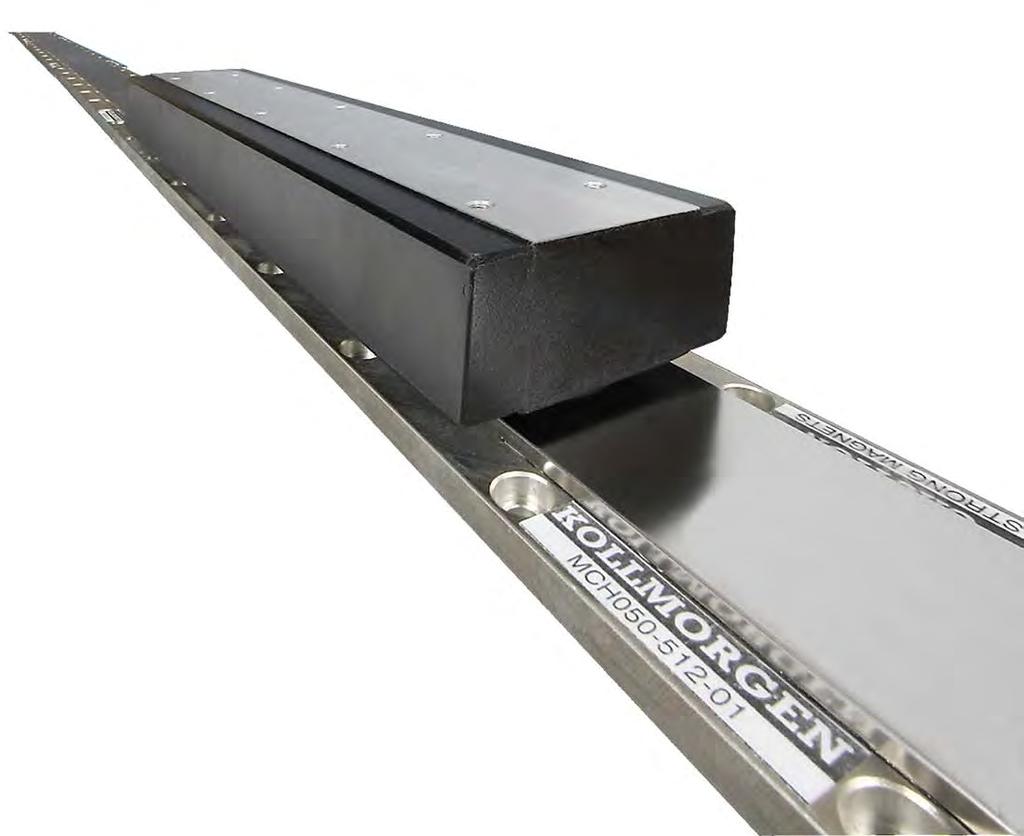
4 D I R E C T D R I V E L I N E A R M O T O R Direct Drive Linear Motor Our direct drive linear motor series provide new dimension in performance with high throughput, accuracy, and zero maintenance. The product line are frameless, permanent magnet, three phase, brushless servomotors. The product line consists of two fundamental constructions, Ironless (slotless) and Ironcore. Ironless motors have no attractive force between the framless components and zero cogging for the ultra smooth motion. Ironcore motors provide the highest force per frame size. They feature a anti-cogging design which yields extremely smooth operation. 4 K O L L M O R G E N


5 The Benefits of Direct Drive Linear Motor Zero Maintenance with Greater Accuracy and Higher Bandwidth Smoother velocity and reduced audible noise Power transmission without backlash Transmission elements such as couplings, toothed belts, ball/lead screws, rack & pinions, and other fitted components can be eliminated No gears or screws, no lubrication required D I R E C T D R I V E L I N E A R M O T O R Wide Range of Sizes and Force to Cover any Linear Application Simplified, High Force Permanent Magnet Design Improved machine reliability Increased performance for the entire system Flat, compact drive solution Easily mix / match motors and drives Real-life acceleration up to 10 G Higher bandwidth and faster response than ball/lead screws or rack & pinion solutions Rapid indexing of heavy loads with peak force up to N Fewer parts and lower cost of ownership More compact machine design No cogging and no attractive force (ironless motors) 5


 High force density Thermal protection PTC and KTY Stainless steel magnet way covers Isolation system for 480 V AC Ironless: Peak force 60 N to 1600 N Continuous force 21 N to 450 N")
6 Direct Drive Linear Motor Overview D I R E C T D R I V E L I N E A R M O T O R O V E R V I E W Kollmorgen Direct Drive Linear DDL Motor Series Kollmorgen supplied its first linear motors in the late 1970 s for use in precision X-Y tables and coating systems. These were brush DC motors using the Kollmorgen patented push-through commutator bar method. This led to development in the early 1980 s of the brushless versions of the linear motor which were used in film processing applications where smooth, high stiffness, linear motion was required. During the past 30 years, advances in permanent magnet material, power semiconductors, and microprocessor technology have been the enablers for increased performance and lower costs for linear motors. DDL motors series ICH comply with the Low Voltage Directive 2014/35/EC for installation in a machine. Safety depends upon installing and configuring motor per the manufacturer s recommendations. The machine in which this product is to be installed must conform to the provisions of EC directive 2014/30/EC. Standard Product Features Ironcore: Peak force ICH series: 405 N to N Continuous force ICH series: 175 N to 5341 N Anti-cogging technique for minimal cogging without magnet skewing High motor constant (K m ) High force density Thermal protection PTC and KTY Stainless steel magnet way covers Isolation system for 480 V AC Ironless: Peak force 60 N to 1600 N Continuous force 21 N to 450 N Zero cogging Zero attractive force Smooth motion for speed as low as 1 micron/second Low mass coil assembly for high acceleration Isolation system for 230 V AC Ironless Motor All Motors: Zero contact, zero maintenance, brushless design 3 phase sinusoidal commutation Peak accelerations easily above 10 G High position accuracy and resolution Very low settling time Low thermal losses Modular magnet design Standard Options: Hall effect feedback (digital) Thermal protection thermistor (PTC, ironless) options Winding options Ironcore Motor 6 K O L L M O R G E N
7 Our Direct Dirve Linear (DDL) motor series are frameless permanent magnet, three phase brushless servomotors. Fundamentally, a linear motor is a rotary motor that is rolled out flat. The two primary components of permanent magnet brushless rotary motors are the stator (primary coils) and the rotor (secondary or rotating magnets). In brushless linear motors the rotor is rolled out flat to become the magnet track (also called the magnet way). The primary coils of the rotary motor are rolled out flat to become the coil assembly (also sometimes called the slider). In most brushless linear motor applications it is typical for the magnet way to be stationary and the coil assembly to be in motion, because of the relative masses of the two components. But it is also perfectly acceptable and sometimes advantageous to reverse this arrangement. The basic electromagnetic operating principles are the same in either case and are identical to those of a rotary motor. Stator N S Windings Air Gap Slider D I R E C T D R I V E L I N E A R M O T O R O V E R V I E W Rotor Rotary Motor Permanent Magnets Linear Motor Base Rotary Motor Rolled Out Flat Direct Drive Linear Motor Options Two types of linear motors are available, Ironcore and Ironless. Each one provides characteristics and features that are optimal depending upon the application. Ironcore motors have coils wound on silicon steel laminations, to maximize the generated force, with a single sided magnet way. Using an innovative electromagnetic design, DDL linear motors have the highest rated force per size, a high K m motor constant (equals low thermal losses), and low cogging forces without the need for skewing of the magnets. The high thrust forces possible with these motors make them ideal for accelerating and moving high masses, and maintaining stiffness during machining or process forces. Ironless motors have no iron, or slots for the coils to be wound on. Therefore, these motors have zero cogging, a very light mass, and absolutely no attractive forces between the coil assembly and the magnet way. These characteristics are ideal for applications requiring very low bearing friction, high acceleration of lighter loads, and for maximizing constant velocity, even at ultra low speeds. The modular magnet ways consists of a double row of magnets to maximize the generated thrust force and to provide a flux return path for the magnetic circuit. Feedback Types All brushless motors require feedback for commutation. For a linear motor, commutation feedback can also be accomplished with a variety of methods. Digital or linear Hall effect devices are available from Kollmorgen for the DDL motor series which allow the drive electronics to commutate the linear motors in a manner identical to rotary motors. For exceptionally smooth motion requirements, sinusoidal drive electronics using digital Hall effects, provide sinusoidal drive currents to the motor for the best constant force and velocity performance. As an alternative, it is typical for linear motor applications to have a linear encoder present in the system for position feedback. It is increasingly common today for drive amplifiers to derive the necessary commutation information directly from this linear encoder, either with or without supplemental digital Hall effect devices on startup. 7
8 Direct Drive Linear Motor Overview D I R E C T D R I V E L I N E A R M O T O R O V E R V I E W Advantages Wide Speed Range Since the frameless parts of the linear motor are non-contact, and no limitations of a mechanical transmission are present, both very high speeds and very low speeds are easily obtainable. Speeds are truly not limited by the motor. Instead, by eliminating the mechanical transmission, speed becomes limited by other elements in the system such as the linear bearings, and the achievable bandwidth from any feedback devices. Application speeds of greater than 5 meters per second or less than 1 micron per second are typically achievable. In comparison, mechanical transmissions such as ball screws are commonly limited to linear speeds of 0.5 to 0.7 meters per second because of resonances and wear. In addition to a wide speed range, linear motors, both ironcore and ironless, have excellent constant velocity characteristics, typically better than ± 0.01% speed variation. High System Dynamics In addition to high speed capability, direct drive linear motors are capable of very high accelerations. Limited only by the system bearings, accelerations of 3 to 5 G are quite typical for the larger motors and accelerations exceeding 10 G are easily achievable for smaller motors. Easy Selection process: 1. Determine peak and continuous force required for your applications (see our applications section on pages 38-41) 2. Use the motor selection guide on pages 8-9 to choose your motor 3. Refer to the appropriate pages in the data publication for technical details 4. Build model number for ordering using pages Smooth Operation and Positional Accuracy Both ironless and ironcore motors exhibit very smooth motion profiles due to the inherent motor design of Kollmorgen's DDL series. Cogging, which is a component of force, is greatly reduced in the ironcore designs and is zero in the ironless designs. As a result, these direct drive linear motors provide very low force and velocity ripple for ultra smooth motion. Positioning accuracies are limited only by the feedback resolution, and sub-micron resolutions are commonly achievable. No Wear or Maintenance Linear motors have few components, therefore the need for ball screw components such as nuts, bearing blocks, couplings, motor mounts and the need to maintain these components have been eliminated. Very long life and clean operation, with no lubrication or maintenance of these parts are the result. Integration of Components is Much Simpler Frameless linear motors require much fewer components than rotary motors with mechanical transmissions. A 0.9 mm airgap for the ironcore design and 0.5 mm airgap for the ironless design is the only alignment of the frameless linear motor components that is necessary. No critical alignments are required as with ball screws. Straightness of travel as provided by the system linear bearings is more than sufficient for the Kollmorgen linear motors. Typical Applications for Linear Motors Include: Machine Tool Drilling Milling Grinding Laser cutting Cam grinding Semiconductor Wafer handling process Wafer-inspection Wafer slicing Tab bonding Wire bonding Ion implantation Lithography Textile Carpet tufting Plasma cutting Polishing Preform injection (plastics) Patient table Handling systems Measurement / Inspection Coordinate measurement machines Electronic assembly Pick-and-place machines Component insertion Screen printers Adhesive dispensers PC-board inspection. drilling Other applications include: Flight Simulators Acceleration sleds Catapult G-Force measurement Textile Carpet tufting Unlimited Travel With the DDL motor series, magnet ways are made in 4 modular sections: 64 mm, 128 mm, 256 mm and 512 mm long. Each module can be added in unlimited numbers to any other module to allow for unlimited travel. Whether the travel required is 1mm or 100 meters the DDL series can accommodate the need. 8 K O L L M O R G E N
9 Notes D I R E C T D R I V E L I N E A R M O T O R S U M M A R Y 9
10 Direct Drive Linear Motor Summary D I R E C T D R I V E L I N E A R M O T O R S U M M A R Y Ironcore Linear Motors Continuous Force N Peak Force N Newtons Max. Force (N) Continuous Peak ICH ICH ICH ICH ICH ICH ICH ICH ICH ICH ICH ICH ICH ICH ICH ICH ICH ICH ICH ICH ICH ICH ICH ICH ICH ICH ICH ICH K O L L M O R G E N
11 Direct Drive Linear Motor Summary Ironless Linear Motors Continuous Force N Peak Force N Newtons Max. Force (N) Continuous Peak IL IL IL IL IL IL IL IL D I R E C T D R I V E L I N E A R M O T O R S U M M A R Y IL IL IL IL IL IL IL IL
 Fc N 175 299 455 612 1000 1200 1507 Motor Constant @ 25 C Km N/ W 26 38 49 59 72 85 96 Electrical Specifications (2) Winding Code (5) A1")
12 ICH11 Performance Data I C H 1 1 P E R F O R M A N C E D A T A Ironcore Motors Series Rated Perfomance Symbol Units ICH ICH ICH ICH ICH ICH ICH Peak Force Fp N Continuous Tmax (1) Fc N Motor 25 C Km N/ W Electrical Specifications (2) Winding Code (5) A1 A5 A1 A5 A1 A5 A1 A5 A1 A5 A1 A5 A1 A5 Peak Current lp Arms Continuous lc Arms Electrical 25 C ±10% Rm Ohms L-L Electrical Inductance ±20% L mh L-L Back EMF 25 C ±10% Ke V peak /(m/s) L-L Force 25 C ±10% Kf N/Arms Mechanical Specifications Coil Assembly Mass ±15% Mc kg Magnetic Way Type MCH030 MCH050 MCH075 MCH100 MCH150 MCH200 MCH250 Magnetic Way Mass ±15% Mw kg/m Figures of Merit and Additional Data Electrical Time Constant Te ms Max.Theoretical Acceleration (3) Amax m/s² Max. Allowable Coil Temp. (4) Tmax C Diameter Dc mm Notes: 1. The motor continuous force is measured with the motor coils achieving the motor maximum allowable temperature Tmax. 2. Alternate windings are available on request. Please consult the Kollmorgen Customer Support for design options. 3. Maximum theoretical acceleration is based on the motors peak force and the motor mass alone. Limitations due to such factors as the additional mass of the load, the bearing type and design, the shock rating of the feedback, the peak current available from the amplifier etc. must be considered to determine the achievable acceleration in each application. 4. Please see our application sizing pages in the back of this guide for more details on sizing and thermal considerations. 5. Winding phase connection: A1: Y (star) windings, A5: (triangle) windings 12 K O L L M O R G E N
13 ICH11 Outline Drawings Ironcore Motors Series STAINLESS STEEL MAGNET COVER COIL ASSEMBLY M5 x 8 MOTOR MOUNTING HOLES 190 Ø 7/Ø 12x5,5 MAGNET WAY MOUNTING HOLES 75 25,1 C MAGNET WAY MOTOR CABLE "B" Resultant airgap = 0.9 mm nominal (0.5 mm minimum) when components are set up to dimension B in table above. Number of holes and typical installation of mulitple ironcore magnet assemblies: please refer to page 21 Option Flying Leads CABLE LENGTH MEASURED FROM HERE TO MOTOR 28 mm W(3) V(2) U(1) PE KTY+ KTY - SHIELD PTC1 PTC2 SHIELD A Ø 12.4 mm WHITE BROWN SHIELD Ø 12.4 mm YELLOW GREEN SHIELD 43,3 9,5 B Ø > 12.4 mm BLACK 6 BLACK 7 SHIELD Ø > 12.4 mm BLACK 4 BLACK 5 SHIELD Motor Coil Coil Width Motor Height Hole Grid Spacing Type A (mm) B (mm) C (mm) ICH ± ± ICH ± ± ICH ± ± ICH ± ± ICH ± ± ICH ± ± ICH ± ± Leads Length (mm) C1 400 C2 200 C3 100 C I C H 1 1 S E R I E S O U T L I N E D R A W I N G S Option Connector on the (Only available for Motors with I c < 9 A) Pin side view (mating view) Extension with pins: BKUA-MR Suggested mating connector BSTA-108-FR (cable mounted) or BDFA-108-FR (flange mounted) Connector Length (mm) P1 400 P2 200 P3 100 P Shield is connected to motor core and connectors case Types Wire Nomenclature Motor Coil Type ICH A1/A5 ICH A1/A5 ICH A1/A5 ICH A1/A5 ICH A1 ICH A5 ICH A1 ICH A5 ICH A1 ICH A5 Type: OLFLEX-SERVO 709 CY 4G x(2X0.34) x(2X0.34) x(2X0.34) x(2X0.34) x(2X0.34) x(2x0.34) x(2x0.34) x(2x0.34) x(2x0.34) x(2x0.34) 12.4 Function 12.4 mm > 12.4 mm Plug BKUA (Option) (1) U Black 1 Black 1 1 V Black 2 Black 2 3 W Black 3 Black 3 4 PE Green/Yellow Green/Yellow PE PTC1 Yellow Black 5 A PTC2 Green Black 6 B KTY + White Black 7 C KTY - Brown Black 8 D Note 1: Option available only for motors with I c < 15 A 13
14 ICH22 Performance Data I C H 2 2 P E R F O R M A N C E D A T A Ironcore Motors Series Rated Perfomance Symbol Units ICH ICH ICH ICH ICH ICH ICH Peak Force Fp N Continuous Tmax (1) Fc N Motor 25 C Km N/ W Electrical Specifications (2) Winding Code (5) A1 A5 A1 A5 A1 A5 A1 A5 A1 A5 A1 A5 A1 A5 Peak Current lp Arms Continuous lc Arms Electrical 25 C ±10% Rm Ohms L-L Electrical Inductance ±20% L mh L-L Back EMF 25 C ±10% Ke V peak /(m/s) L-L Force 25 C ±10% Kf N/Arms Mechanical Specifications Coil Assembly Mass ±15% Mc kg Magnetic Way Type MCH030 MCH050 MCH075 MCH100 MCH150 MCH200 MCH250 Magnetic Way Mass ±15% Mw kg/m Figures of Merit and Additional Data Electrical Time Constant Te ms Max.Theoretical Acceleration(3) Amax m/s² Max. Allowable Coil Temp. (4) Tmax C Diameter Dc mm Notes: 1. The motor continuous force is measured with the motor coils achieving the motor maximum allowable temperature Tmax. 2. Alternate windings are available on request. Please consult the Kollmorgen Customer Support for design options. 3. Maximum theoretical acceleration is based on the motors peak force and the motor mass alone. Limitations due to such factors as the additional mass of the load, the bearing type and design, the shock rating of the feedback, the peak current available from the amplifier etc. must be considered to determine the achievable acceleration in each application. 4. Please see our application sizing pages in the back of this guide for more details on sizing and thermal considerations. 5. Winding phase connection: A1: Y (star) windings, A5: (triangle) windings 14 K O L L M O R G E N
15 ICH22 Outline Drawings Ironcore Motors Series MOTOR-WAY ASSEMBLY ICH22-XXX STAINLESS STEEL MAGNET COVER 75 38,1 COIL ASSEMBLY MAGNET WAY M5 x 8 MOTOR MOUNTING HOLES 375 MOTOR CABLE Ø 7/Ø 12x5,5 MAGNET WAY MOUNTING HOLES C B A ,3 9,5 B Motor Coil Coil Width Motor Height Hole Grid Spacing Type A (mm) B (mm) C (mm) ICH ± ± ICH ± ± ICH ± ± ICH ± ± ICH ± ± ICH ± ± ICH ± ± I C H 2 2 P E R F O R M A N C E D A T A Resultant airgap = 0.9 mm nominal (0.5 mm minimum) when components are set up to dimension B in table above. Number of holes and typical installation of mulitple ironcore magnet assemblies: please refer to page 21 Option Flying Leads CABLE LENGTH MEASURED FROM HERE TO MOTOR 28 mm W(3) V(2) U(1) PE Ø 12.4 mm KTY+ WHITE KTY - BROWN SHIELD SHIELD Ø 12.4 mm PTC1 YELLOW PTC2 GREEN SHIELD SHIELD Ø > 12.4 mm BLACK 6 BLACK 7 SHIELD Ø > 12.4 mm BLACK 4 BLACK 5 SHIELD Leads Length (mm) C1 400 C2 200 C3 100 C Option Connector on the (Only available for Motors with I c < 9 A) Pin side view (mating view) Extension with pins: BKUA-MR Suggested mating connector BSTA-108-FR (cable mounted) or BDFA-108-FR (flange mounted) Connector Length (mm) P1 400 P2 200 P3 100 P Shield is connected to motor core and connectors case Types Wire Nomenclature Motor Coil Type ICH A1/A5 ICH A1/A5 ICH A1 ICH A5 ICH A1 ICH A5 ICH A1 ICH A5 ICH A1 ICH A5 ICH A1 ICH A5 Type: OLFLEX-SERVO 709 CY 4G x(2X0.34) x(2X0.34) x(2X0.34) x(2x0.34) x(2x0.34) x(2x0.75) x(2x0.34) x(2x0.75) x(2x0.34) x(2x0.75) x(2x0.34) x(2x0.75) 13.6 Function 12.4 mm > 12.4 mm Plug BKUA (Option) (1) U Black 1 Black 1 1 V Black 2 Black 2 3 W Black 3 Black 3 4 PE Green/Yellow Green/Yellow PE PTC1 Yellow Black 5 A PTC2 Green Black 6 B KTY + White Black 7 C KTY - Brown Black 8 D Note 1: Option available only for motors with I c < 15 A 15
 Fc N 511 769 1171 1575 2387 3201 4016 Motor Constant @ 25 C Km N/ W 45 65 85 101 128 151 171 Electrical Specifications (2) Winding")
16 ICH33 Performance Data I C H 3 3 P E R F O R M A N C E D A T A Ironcore Motors Series Rated Perfomance Symbol Units ICH ICH ICH ICH ICH ICH ICH Peak Force Fp N Continuous Tmax (1) Fc N Motor 25 C Km N/ W Electrical Specifications (2) Winding Code (5) A1 A5 A1 A5 A1 A5 A1 A5 A1 A5 A1 A5 A1 A5 Peak Current lp Arms Continuous lc Arms Electrical 25 C ±10% Rm Ohms L-L Electrical Inductance ±20% L mh L-L Back EMF 25 C ±10% Ke V peak /(m/s) L-L Force 25 C±10% Kf N/Arms Mechanical Specifications Coil Assembly Mass ±15% Mc kg Magnetic Way Type MCH030 MCH050 MCH075 MCH100 MCH150 MCH200 MCH250 Magnetic Way Mass ±15% Mw kg/m Figures of Merit and Additional Data Electrical Time Constant Te ms Max.Theoretical Acceleration(3) Amax m/s² Max. Allowable Coil Temp. (4) Tmax C Diameter Dc mm Notes: 1. The motor continuous force is measured with the motor coils achieving the motor maximum allowable temperature Tmax. 2. Alternate windings are available on request. Please consult the Kollmorgen Customer Support for design options. 3. Maximum theoretical acceleration is based on the motors peak force and the motor mass alone. Limitations due to such factors as the additional mass of the load, the bearing type and design, the shock rating of the feedback, the peak current available from the amplifier etc. must be considered to determine the achievable acceleration in each application. 4. Please see our application sizing pages in the back of this guide for more details on sizing and thermal considerations. 5. Winding phase connection: A1: Y (star) windings, A5: (triangle) windings 16 K O L L M O R G E N
17 ICH33 Outline Drawings Ironcore Motors Series MOTOR-WAY ASSEMBLY ICH33-XXX STAINLESS STEEL MAGNET COVER COIL ASSEMBLY 75 51,1 MAGNET WAY C A 15 M5 x 8 MOTOR MOUNTING HOLES 542 MOTOR CABLE Ø 7/Ø 12x5,5 MAGNET WAY MOUNTING HOLES 15 43,3 9,5 B Motor Coil Coil Width Motor Height Hole Grid Spacing Type A (mm) B (mm) C (mm) ICH ± ± ICH ± ± ICH ± ± ICH ± ± ICH ± ± ICH ± ± ICH ± ± I C H 3 3 P E R F O R M A N C E D A T A B Resultant airgap = 0.9 mm nominal (0.5 mm minimum) when components are set up to dimension B in table above. Number of holes and typical installation of mulitple ironcore magnet assemblies: please refer to page 21 Option Flying Leads CABLE LENGTH MEASURED FROM HERE TO MOTOR 28 mm W(3) V(2) U(1) PE Ø 12.4 mm KTY+ WHITE KTY - BROWN SHIELD SHIELD Ø 12.4 mm PTC1 YELLOW PTC2 GREEN SHIELD SHIELD Ø > 12.4 mm BLACK 6 BLACK 7 SHIELD Ø > 12.4 mm BLACK 4 BLACK 5 SHIELD Leads Length (mm) C1 400 C2 200 C3 100 C Option Connector on the (Only available for Motors with I c < 9 A) Pin side view (mating view) Extension with pins: BKUA-MR Suggested mating connector BSTA-108-FR (cable mounted) or BDFA-108-FR (flange mounted) Connector Length (mm) P1 400 P2 200 P3 100 P Shield is connected to motor core and connectors case Types Wire Nomenclature Motor Coil Type ICH A1/A5 ICH A1 ICH A5 ICH A1 ICH A5 ICH A1 ICH A5 ICH A1 ICH A5 ICH A1 ICH A5 ICH A1 ICH A5 Type: OLFLEX-SERVO 709 CY 4G x(2X0.34) x(2x0.34) x(2x0.75) x(2x0.34) x(2x0.75) x(2x0.34) x(2x0.75) x(2x0.34) x(2x0.75) x(2x0.34) x(2x1.0) x(2x0.34) x(2x1.0) 16.3 Function 12.4 mm > 12.4 mm Plug BKUA (Option) (1) U Black 1 Black 1 1 V Black 2 Black 2 3 W Black 3 Black 3 4 PE Green/Yellow Green/Yellow PE PTC1 Yellow Black 5 A PTC2 Green Black 6 B KTY + White Black 7 C KTY - Brown Black 8 D Note 1: Option available only for motors with I c < 15 A 17
 Fc N 600 1023 1557 2095 3175 4258 5341 Motor Constant @ 25 C Km N/ W 52 75 98 117 148 175 198 Electrical Specifications (2) Winding")
18 ICH44 Performance Data I C H 4 4 P E R F O R M A N C E D A T A Ironcore Motors Series Rated Perfomance Symbol Units ICH ICH ICH ICH ICH ICH ICH Peak Force Fp N Continuous Tmax (1) Fc N Motor 25 C Km N/ W Electrical Specifications (2) Winding Code (5) A1 A5 A1 A5 A1 A5 A1 A5 A1 A5 A1 A5 A1 A5 Peak Current lp Arms Continuous lc Arms Electrical 25 C ±10% Rm Ohms L-L Electrical Inductance ±20% L mh L-L Back EMF C ±10% Ke V peak /(m/s) L-L Force 25 C ±10% Kf N/Arms Mechanical Specifications Coil Assembly Mass ±15% Mc kg Magnetic Way Type MCH030 MCH050 MCH075 MCH100 MCH150 MCH200 MCH250 Magnetic Way Mass ±15% Mw kg/m Figures of Merit and Additional Data Electrical Time Constant Te ms Max.Theoretical Acceleration(3) Amax m/s² Max. Allowable Coil Temp. (4) Tmax C Diameter Dc mm Notes: 1. The motor continuous force is measured with the motor coils achieving the motor maximum allowable temperature Tmax. 2. Alternate windings are available on request. Please consult the Kollmorgen Customer Support for design options. 3. Maximum theoretical acceleration is based on the motors peak force and the motor mass alone. Limitations due to such factors as the additional mass of the load, the bearing type and design, the shock rating of the feedback, the peak current available from the amplifier etc. must be considered to determine the achievable acceleration in each application. 4. Please see our application sizing pages in the back of this guide for more details on sizing and thermal considerations. 5. Winding phase connection: A1: Y (star) windings, A5: (triangle) windings 18 K O L L M O R G E N
 B (mm) C (mm) ICH44-030 60.0 ± 1.0 58.6 ± 0.1 16.0 ICH44-050 80.0 ± 1.0 58.6 ± 0.1 36.")
19 ICH44 Outline Drawings Ironcore Motors Series MOTOR-WAY ASSEMBLY ICH44-XXX STAINLESS STEEL MAGNET COVER COIL ASSEMBLY 75 26,6 MAGNET WAY C A 15 M5 x 8 MOTOR MOUNTING HOLES MOTOR CABLE 718 Ø 7/Ø 12x5,5 MAGNET WAY MOUNTING HOLES 15 43,3 9,5 B Motor Coil Coil Width Motor Height Hole Grid Spacing Type A (mm) B (mm) C (mm) ICH ± ± ICH ± ± ICH ± ± ICH ± ± ICH ± ± ICH ± ± ICH ± ± I C H 4 4 P E R F O R M A N C E D A T A B Resultant airgap = 0.9 mm nominal (0.5 mm minimum) when components are set up to dimension B in table above. Number of holes and typical installation of mulitple ironcore magnet assemblies: please refer to page 21 Option Flying Leads CABLE LENGTH MEASURED FROM HERE TO MOTOR 28 mm W(3) V(2) U(1) PE Ø 12.4 mm KTY+ WHITE KTY - BROWN SHIELD SHIELD Ø 12.4 mm PTC1 YELLOW PTC2 GREEN SHIELD SHIELD Ø > 12.4 mm BLACK 6 BLACK 7 SHIELD Ø > 12.4 mm BLACK 4 BLACK 5 SHIELD Leads Length (mm) C1 400 C2 200 C3 100 C Option Connector on the (Only available for Motors with I c < 9 A) Pin side view (mating view) Extension with pins: BKUA-MR Suggested mating connector BSTA-108-FR (cable mounted) or BDFA-108-FR (flange mounted) Connector Length (mm) P1 400 P2 200 P3 100 P Shield is connected to motor core and connectors case Types Wire Nomenclature Motor Coil Type ICH A1/A5 ICH A1/A5 ICH A1 ICH A5 ICH A1 ICH A5 ICH A1 ICH A5 ICH A1 ICH A5 ICH A1 ICH A5 Type: OLFLEX-SERVO 709 CY 4G x(2X0.34) x(2X0.34) x(2x0.34) x(2x0.75) x(2x0.34) x(2x0.75) x(2x0.75) x(2x1.00+2x1.50) x(2x0.75) x(2x1.00+2x1.50) x(2x0.75) x(2x1.00+2x1.50) 16.7 Function 12.4 mm > 12.4 mm Plug BKUA (Option) (1) U Black 1 Black 1 1 V Black 2 Black 2 3 W Black 3 Black 3 4 PE Green/Yellow Green/Yellow PE PTC1 Yellow Black 5 A PTC2 Green Black 6 B KTY + White Black 7 C KTY - Brown Black 8 D Note 1: Option available only for motors with I c < 15 A 19
20 Ironcore Magnet Ways I R O N C O R E M A G N E T W A Y S MCHxxx-064 Ø 3 x 3 Pole mark "W" ±0,3 7,5 * 32 8 * ,1 0,4 "W2" ±0,2 MCHXXX POLE MARKS TO BE LOCATED ON SAME SIDE TO INSURE CORRECT NORTH/SOUTH POLE ORIENTATION 2 MOUNTING HOLES Ø 7Ø 12x5.5 STAINLESS STEEL MAGNET COVER "J" * "H" ±0,2 Ø 7/Ø 12x5,5 * - for reference only STAINLESS STEEL MAGNET COVER Magnet assembiles are modular and can be installed in multiples of same or alternate lengths. Standard lengths are shown below. Magnetic Way Type Assembly Width W (mm) Mounting Hole Width W2 (mm) J (mm) H With Cover (mm) MCH MCH MCH MCH MCH MCH MCH MCHxxx-128 MCHXXX Ø 3 x 3 Pole mark POLE MARKS TO BE LOCATED ON SAME SIDE TO INSURE CORRECT NORTH/SOUTH POLE ORIENTATION 8 * 64 ±0,2 4 MOUNTING HOLES Ø 7/Ø 12x5,5 STAINLESS STEEL MAGNET COVER "H" ±0,2 Magnetic Way Type Assembly Width W (mm) Mounting Hole Width W (mm) J (mm) H With Cover (mm) "W" ±0,3 7,5 * ,1 0,4 "W2" ±0,2 "J" * Ø 7/Ø 12x5,5 * - for reference only STAINLESS STEEL MAGNET COVER MCH MCH MCH MCH MCH MCH MCH MCHxxx-256 Ø 3 x 3 Pole mark "W" ±0,3 7,5 * MCHXXX POLE MARKS TO BE LOCATED ON SAME SIDE TO INSURE CORRECT NORTH/SOUTH POLE ORIENTATION 8 * 8 MOUNTING HOLES STAINLESS STEEL 64 ±0,2 Ø 7/Ø 12x5,5 MAGNET COVER "H" ±0, ,1 0,4 "W2" ±0,2 "J" * Ø 7/Ø 12x5,5 * - for reference only STAINLESS STEEL MAGNET COVER Magnetic Way Type Assembly Width W (mm) Mounting Hole Width W2 (mm) J (mm) H With Cover (mm) MCH MCH MCH MCH MCH MCH MCH * Note: Flatness and height of magnet ways is defined at fastened to the flat base. 20 K O L L M O R G E N
21 MCHxxx-512 Ø 3 x 3 Pole mark "W" ±0,3 7,5 * 32 8 * 64 ±0,2 MCHXXX POLE MARKS TO BE LOCATED ON SAME SIDE TO INSURE CORRECT NORTH/SOUTH POLE ORIENTATION 16 MOUNTING HOLES Ø 7/Ø 12x5, ,1 0,4 STAINLESS STEEL MAGNET COVER "W2" ±0,2 "J" * "H" ±0,2 Ø 7/Ø 12x5,5 *for reference only STAINLESS STEEL MAGNET COVER Magnetic Way Type Assembly Width W (mm) Mounting Hole Width W2 (mm) J (mm) H With Cover (mm) MCH MCH MCH MCH MCH MCH MCH I R O N C O R E M A G N E T W A Y S Typical Installation of Multiple Ironcore Magnet Assemblies MAGNET WAY INSTALLATION 32 * 8 * POLE MARK TO BE LOCATED ON SAME SIDE TO ENSURE CORRECT NORTH/SOUTH POLE ORIENTATION 64± ± ±0.1 POLE MARK TO BE LOCATED ON SAME SIDE TO ENSURE CORRECT NORTH/SOUTH POLE ORIENTATION S N S N S N S N S N S N S N S N S N S N S N S N Magnet Way widths correspond to the mating coil assembly width. Magnet Way assemblies are modular and come in standard lengths: 64, 128, 256, 512 mm. Multiple magnet assemblies can be installed to obtain the desired length. Shown below is the method to mount multiple assemblies * - for reference only Typical Mounting Bar Lengths & Mounting Holes Tabulation "S" "C" M5X8 "N" NUMBER OF HOLES ROWS WILL VARY WITH MOTOR WIDTH Magnetic Coil Type Number of Rows N Spacing Bet. Holes C (mm) Mounting Bar Length L (mm) S (mm) "L" ICHXX ICHXX ICHXX ICHXX ICHXX ICHXX ICHXX * Note: Flatness and height of magnet ways is defined at fastened to the flat base. 21
22 IL06 Performance Data I L 0 6 P E R F O R M A N C E D A T A Ironless Non-Cooled Motors Series Rated Perfomance Symbol Units IL IL IL IL Peak Force Fp N Continuous Tmax (1) Fc N Motor Constant Km N W Electrical Specifications (2) Winding Code A1 A4 A1 A4 A1 A4 A1 A4 Peak Current lp Arms Continuous lc Arms Electrical 25 C±10% Rm Ohms L-L Electrical Inductance ±20% L mh L-L Back EMF 25 C±10% Ke Vpeak/m/s L-L Force 25 C±10% kf N/Arms Mechanical Specifications Coil Assembly Mass ±15% Mc kg Magnetic Way Type MW MW MW075 MW L L Magnetic Way Mass ±15% Mw kg/m Figures of Merit and Additional Data Electrical Time Constant Te ms Max.Theoretical Acceleration (3) Amax m/s² Magnetic Attraction Fa kn Thermal Resistance (4) (Coils to External Structure) Rth C/Watt Max. Allowable Coil Temp. (4) Tmax C Notes: 1. The motor continuous rated force is measured with the motor coils achieving the motor maximum allowable temperature Tmax. 2. Alternate windings can be made available. Please consult the Kollmorgen Customer Support for design options. 3. Maximum theoretical acceleration is based on the motors peak force and the motor mass alone. Limitations due to such factors as the additional mass of the load, the bearing type and design, the shock rating of the feedback, the peak current available from the amplifier etc. must be considered to determine the achievable acceleration in each application. 4. Please see our application sizing pages in the back of this guide for more details on sizing and thermal considerations. 22 K O L L M O R G E N
23 IL06 Outline Drawings Ironless Non-Cooled Motors Series FOR MOTOR CABLE AND HALL EFFECT MTG. SEE DRAWING BELOW BOTH SIDES MAX PL. BOTH SIDES M5 X 0.8 X 5 DP. 6 PL., 3 PER SIDE 3.9 M5 X 0.8 X 5 DP. 4 PL "A" "T" "B" Motor Coil Coil Width Typ. Assy. Width Typ. Assy. Width +0.7 A (mm) -0.3 B ± 0.6 (mm) T ± 0.4 (mm) IL IL L IL IL L IL IL COIL ASSEMBLY CLEARANCE- SET UP DIM. COIL TO MAGNET AIRGAP 0.74 REF TYP. FOR 030, REF TYP. FOR -075 AND -100 MAGNET WAY REF. Notes: 1. Dimensions in mm 2. Tolerances unless otherwise specified: no decimal place ±0.8 X decimal place ±0.1 XX decimal place ±0.05 I L 0 6 O U T L I N E D R A W I N G S Termination and Hall Effect Options 12.2 ±0.3 THERMAL 1 2 PIN 1 THERMAL PROTECTION CONNECTOR: 2 PIN - MALE CONNECTOR FREE HANGING RECEPTACLE MOLEX P/N FEMALE TERMINALS MOLEX P/N MATING CONNECTOR REFERENCE: MOLEX "MICRO-FIT 3.0" PLUG: MALE TERMINALS: SEE WIRE TABLE, PAGE ± ± ±0.3 MOTOR CABLE HALL EFFECT CONNECTOR OPTION: POSITRONIC P/N: MD9M2000Z 9 PIN, MALE MOTOR OPTIONAL HALL EFFECT AS SHOWN, MOUNTING HOLES M3 X 6.3 MIN. DP. 2 PL PIN 1 PIN 5 PIN 9 STANDARD LENGTH, SEE TABLE #4-40 JACKNUT (2) (REMOVABLE FOR BULKHEAD MOUNTING) COIL ASSEMBLY REF COIL ASSEMBLY REF MOTOR CONNECTOR: POSITRONIC P/N: CBD3W3M0000Z 3 PIN MALE, SHELL SIZE 2 MALE CONTACTS: POSITRONIC P/N: MS40--D 3 REMOVABLE MALE CONTACTS, SIZE 8 MATING CONNECTOR REFERENCE: POSITRONIC P/N: CBD3W3F0000X 3 FEMALE SOCKETS, SOLDER TYPE, SIZE 8, POSITRONIC P/N: FS40--D SEE WIRE TABLE, PAGE 36 MATING CONNECTOR REFERENCE: POSITRONIC P/N: MD9F2000X HALL EFFECT SEE WIRE TABLE, PAGE 36 PIN 1 HALL EFFECT ASSEMBLY STANDARD LENGTH, SEE TABLE 21.0 MAX. HALL EFFECT MASS W/P* CONNECTOR: 0.05KG MAX W/C* CABLE: 0.03KG MAX Connector Option Connector Length (mm) P1 400 P2 200 P3 100 P Flying Lead Option Leads Length (mm) C1 400 C2 200 C3 100 C
24 IL12 Performance Data I L 1 2 P E R F O R M A N C E D A T A Ironless Non-Cooled Motors Series Rated Perfomance Symbol Units IL IL IL IL Peak Force Fp N Continuous Tmax (1) Fc N Motor 25 C Km N W Electrical Specifications (2) Winding Code A1 A2 A4 A1 A2 A4 A1 A2 A4 A2 A4 Peak Current lp Arms Continuous lc Arms Electrical 25 C±10% Rm Ohms L-L Electrical Inductance ±20% L mh L-L Back EMF 25 C±10% Ke Vpeak/m/s L-L Force 25 C±10% Kf N/Arms Mechanical Specifications Coil Assembly Mass ±15% Mc kg MW MW MW075 MW100 Magnetic Way Type L L Magnetic Way Mass ±15% Mw kg/m Figures of Merit and Additional Data Electrical Time Constant Te ms Max.Theoretical Acceleration (3) Amax m/s² Magnetic Attraction Fa kn Thermal Resistance (4) (coils to external structure) Rth C/Watt Max. Allowable Coil Temp. (4) Tmax C Notes: 1. The motor continuous rated force is measured with the motor coils achieving the motor maximum allowable temperature Tmax. 2. Alternate windings can be made available. Please consult the Kollmorgen Customer Support for design options. 3. Maximum theoretical acceleration is based on the motors peak force and the motor mass alone. Limitations due to such factors as the additional mass of the load, the bearing type and design, the shock rating of the feedback, the peak current available from the amplifier etc. must be considered to determine the achievable acceleration in each application. 4. Please see our application sizing pages in the back of this guide for more details on sizing and thermal considerations. 24 K O L L M O R G E N
25 IL12 Outline Drawings Ironless Non-Cooled Motors Series FOR MOTOR CABLE AND HALL EFFECT MTG. SEE DRAWING BELOW BOTH SIDES PL. BOTH SIDES M5 X 0.8 X 5 DP. 8 PL PL MAX "A" Magnet Way REF. "B" Coil Width Typ. Assy. Width Typ. Assy. Width Motor Coil A +0.7 (mm) -0.3 B ±0.6 (mm) T ±0.4 (mm) IL IL L IL IL L IL IL COIL ASSEMBLY CLEARANCE- SET UP DIM. Notes: 1. Dimensions in mm 2. Tolerances unless otherwise specified: no decimal place ±0.8 X decimal place ±0.1 XX decimal place ±0.05 I L 1 2 O U T L I N E D R A W I N G S M5 X 0.8 X 5 DP. 10 PL., 5 PER SIDE COIL TO MAGNET AIRGAP 0.74 REF TYP. FOR 030, REF TYP. FOR -075 AND -100 "T" Termination and Hall Effect Options 12.2 ±0.3 THERMAL 1 2 PIN 1 THERMAL PROTECTION CONNECTOR: 2 PIN - MALE CONNECTOR FREE HANGING RECEPTACLE MOLEX P/N FEMALE TERMINALS MOLEX P/N MATING CONNECTOR REFERENCE: MOLEX "MICRO-FIT 3.0" PLUG: MALE TERMINALS: SEE WIRE TABLE, PAGE ± ± ±0.3 MOTOR CABLE HALL EFFECT CONNECTOR OPTION: POSITRONIC P/N: MD9M2000Z 9 PIN, MALE MOTOR OPTIONAL HALL EFFECT AS SHOWN, MOUNTING HOLES M3 X 6.3 MIN. DP. 2 PL PIN 1 PIN 5 PIN 9 STANDARD LENGTH, SEE TABLE #4-40 JACKNUT (2) (REMOVABLE FOR BULKHEAD MOUNTING) COIL ASSEMBLY REF COIL ASSEMBLY REF MOTOR CONNECTOR: POSITRONIC P/N: CBD3W3M0000Z 3 PIN MALE, SHELL SIZE 2 MALE CONTACTS: POSITRONIC P/N: MS40--D 3 REMOVABLE MALE CONTACTS, SIZE 8 MATING CONNECTOR REFERENCE: POSITRONIC P/N: CBD3W3F0000X 3 FEMALE SOCKETS, SOLDER TYPE, SIZE 8, POSITRONIC P/N: FS40--D SEE WIRE TABLE, PAGE 36 MATING CONNECTOR REFERENCE: POSITRONIC P/N: MD9F2000X HALL EFFECT SEE WIRE TABLE, PAGE 36 PIN 1 HALL EFFECT ASSEMBLY STANDARD LENGTH, SEE TABLE 21.0 MAX. HALL EFFECT MASS W/P* CONNECTOR: 0.05KG MAX W/C* CABLE: 0.03KG MAX Connector Option Connector Length (mm) P1 400 P2 200 P3 100 P Flying Lead Option Leads Length (mm) C1 400 C2 200 C3 100 C
26 IL18 Performance Data I L 1 8 P E R F O R M A N C E D A T A Ironless Non-Cooled Motors Series Rated Perfomance Symbol Units IL IL Peak Force Fp N Continuous Tmax (1) Fc N Motor 25 C Km N W Electrical Specifications (2) Winding Code A1 A2 A3 A4 A1 A2 A3 A4 Peak Current lp Arms Continuous lc Arms Electrical 25 C±10% Rm Ohms L-L Electrical Inductance ±20% L mh L-L Back EMF 25 C±10% Ke Vpeak/m/s L-L Force 25 C±10% Kf N/Arms Mechanical Specifications (2) Coil Assembly Mass ±15% Mc kg MW MW Magnetic Way Type L L Magnetic Way Mass ±15% Mw kg/m Figures of Merit and Additional Data Electrical Time Constant Te ms Max.Theoretical Acceleration (3) Amax m/s² Magnetic Attraction Fa kn 0 0 Thermal Resistance (4) (coils to external structure) Rth C/Watt Max. Allowable Coil Temp. (4) Tmax C Notes: 1. The motor continuous rated force is measured with the motor coils achieving the motor maximum allowable temperature Tmax. 2. Alternate windings can be made available. Please consult the Kollmorgen Customer Support for design options. 3. Maximum theoretical acceleration is based on the motors peak force and the motor mass alone. Limitations due to such factors as the additional mass of the load, the bearing type and design, the shock rating of the feedback, the peak current available from the amplifier etc. must be considered to determine the achievable acceleration in each application. 4. Please see our application sizing pages in the back of this guide for more details on sizing and thermal considerations. 26 K O L L M O R G E N
27 Rated Perfomance Symbol Units IL IL Peak Force Fp N Continuous Tmax (1) Fc N Motor 25 C Km N W Electrical Specifications (2) Winding Code A1 A2 A3 A4 A1 A2 A3 A4 Peak Current lp Arms Continuous lc Arms Electrical 25 C±10% Rm Ohms L-L Electrical Inductance ±20% L mh L-L Back EMF 25 C±10% Ke Vpeak/m/s L-L Force 25 C±10% Kf N/Arms Mechanical Specifications Coil Assembly Mass ±15% Mc kg Magnetic Way Type MW075 MW100 Magnetic Way Mass ±15% Mw kg/m Figures of Merit and Additional Data Electrical Time Constant Te ms Max.Theoretical Acceleration (3) Amax m/s² Magnetic Attraction Fa kn 0 0 Thermal Resistance (4) (coils to external structure) Rth C/Watt Max. Allowable Coil Temp. (4) Tmax C I L 1 8 P E R F O R M A N C E D A T A Notes: 1. The motor continuous rated force is measured with the motor coils achieving the motor maximum allowable temperature Tmax. 2. Alternate windings can be made available. Please consult the Kollmorgen Customer Support for design options. 3. Maximum theoretical acceleration is based on the motors peak force and the motor mass alone. Limitations due to such factors as the additional mass of the load, the bearing type and design, the shock rating of the feedback, the peak current available from the amplifier etc. must be considered to determine the achievable acceleration in each application. 4. Please see our application sizing pages in the back of this guide for more details on sizing and thermal considerations. 27
28 IL18 Outline Drawings I L 1 8 O U T L I N E D R A W I N G S Ironless Non-Cooled Motors Series FOR MOTOR CABLE AND HALL EFFECT MTG. SEE DRAWING BELOW PL. BOTH SIDES MAX PL MAGNET WAY REF. BOTH SIDES COIL ASSEMBLY M5 X 0.8 X 5 DP. 14 PL., 7 PER SIDE M5 X 0.8 X 5 DP. 12 PL. "A" 3.9 "B" 16.7 Motor Coil Coil Width Typ. Assy. Width Typ. Assy. Width A (mm) B ± 0.6 (mm) T ± 0.4 (mm) IL IL L IL IL L IL IL CLEARANCE- SET UP DIM. COIL TO MAGNET AIRGAP 0.74 REF TYP. FOR 030, REF TYP. FOR -075 AND -100 Notes: 1. Dimensions in mm 2. Tolerances unless otherwise specified: no decimal place ±0.8 X decimal place ±0.1 XX decimal place ±0.05 "T" Termination and Hall Effect Options 12.2 ±0.3 THERMAL 1 2 PIN 1 THERMAL PROTECTION CONNECTOR: 2 PIN - MALE CONNECTOR FREE HANGING RECEPTACLE MOLEX P/N FEMALE TERMINALS MOLEX P/N MATING CONNECTOR REFERENCE: MOLEX "MICRO-FIT 3.0" PLUG: MALE TERMINALS: SEE WIRE TABLE, PAGE ± ± ±0.3 MOTOR CABLE HALL EFFECT CONNECTOR OPTION: POSITRONIC P/N: MD9M2000Z 9 PIN, MALE MOTOR OPTIONAL HALL EFFECT AS SHOWN, MOUNTING HOLES M3 X 6.3 MIN. DP. 2 PL PIN 1 PIN 5 PIN 9 STANDARD LENGTH, SEE TABLE #4-40 JACKNUT (2) (REMOVABLE FOR BULKHEAD MOUNTING) COIL ASSEMBLY REF COIL ASSEMBLY REF MOTOR CONNECTOR: POSITRONIC P/N: CBD3W3M0000Z 3 PIN MALE, SHELL SIZE 2 MALE CONTACTS: POSITRONIC P/N: MS40--D 3 REMOVABLE MALE CONTACTS, SIZE 8 MATING CONNECTOR REFERENCE: POSITRONIC P/N: CBD3W3F0000X 3 FEMALE SOCKETS, SOLDER TYPE, SIZE 8, POSITRONIC P/N: FS40--D SEE WIRE TABLE, PAGE 36 MATING CONNECTOR REFERENCE: POSITRONIC P/N: MD9F2000X HALL EFFECT SEE WIRE TABLE, PAGE 36 PIN 1 HALL EFFECT ASSEMBLY STANDARD LENGTH, SEE TABLE 21.0 MAX. HALL EFFECT MASS W/P* CONNECTOR: 0.05KG MAX W/C* CABLE: 0.03KG MAX Connector Option Connector Length (mm) P1 400 P2 200 P3 100 P Flying Lead Option Leads Length (mm) C1 400 C2 200 C3 100 C K O L L M O R G E N
29 Notes I L 1 8 O U T L I N E D R A W I N G S 29
30 IL24 Performance Data I L 2 4 P E R F O R M A N C E D A T A Ironless Non-Cooled Motors Series Rated Perfomance Symbol Units IL IL IL IL Peak Force Fp N Continuous Tmax (1) Fc N Motor 25 C Km N W Electrical Specifications (2) Winding Code A1 A2 A3 A1 A2 A3 A1 A2 A3 A4 A1 A2 A3 A4 Peak Current lp Arms Continuous lc Arms Electrical 25 C±10% Rm Ohms L-L Electrical Inductance ±20% L mh L-L Back EMF 25 C±10% Ke Vpeak/m/s L-L Force Constant N/Arms C±10%ww lbf/arms Mechanical Specifications Coil Assembly Mass ±15% Mc kg MW MW MW MW Magnetic Way Type L L Magnetic Way Mass ±15% Mw kg/m Figures of Merit and Additional Data Electrical Time Constant Te ms Max.Theoretical Acceleration(3) Amax m/s² Magnetic Attraction Fa kn Thermal Resistance (4) (coils to external structure) Rth C/Watt Max. Allowable Coil Temp. (4) Tmax C Notes: 1. The motor continuous rated force is measured with the motor coils achieving the motor maximum allowable temperature Tmax. 2. Alternate windings can be made available. Please consult the Kollmorgen Customer Support for design options. 3. Maximum theoretical acceleration is based on the motors peak force and the motor mass alone, Limitations due to such factors as the additional mass of the load, the bearing type and design, the shock rating of the feedback, the peak current available from the amplifier etc. must be considered to determine the achievable acceleration in each application. 4. Please see our application sizing pages in the back of this guide for more details on sizing and thermal considerations. 30 K O L L M O R G E N
31 IL24 Outline Drawings Ironless Non-Cooled Motors Series FOR MOTOR CABLE AND HALL EFFECT MTG. SEE PAGE 19 M5 X 0.8 X 5 DP. 20 PL., 10 PER SIDE PL MAX PL. BOTH SIDES BOTH SIDES 4.0 MAGNET WAY REF. COIL ASSEMBLY M5 X 0.8 X 5 DP. 18 PL., 9 PER SIDE Termination and Hall Effect Options "A" "B" Motor Coil Coil Width Typ. Assy. Width Typ. Assy. Width A (mm) B ± 0.6 (mm) T ± 0.4 (mm) IL IL L IL IL L IL IL "T" CLEARANCE- SET UP DIM. COIL TO MAGNET AIRGAP 0.74 REF TYP. FOR 030, REF TYP. FOR -075 AND -100 Notes: 1. Dimensions in mm 2. Tolerances unless otherwise specified: no decimal place ±0.8 X decimal place ±0.1 XX decimal place ±0.05 I L 2 4 O U T L I N E D R A W I N G S 12.2 ±0.3 THERMAL 1 2 PIN 1 THERMAL PROTECTION CONNECTOR: 2 PIN - MALE CONNECTOR FREE HANGING RECEPTACLE MOLEX P/N FEMALE TERMINALS MOLEX P/N MATING CONNECTOR REFERENCE: MOLEX "MICRO-FIT 3.0" PLUG: MALE TERMINALS: SEE WIRE TABLE, PAGE ± ± ±0.3 MOTOR CABLE HALL EFFECT CONNECTOR OPTION: POSITRONIC P/N: MD9M2000Z 9 PIN, MALE MOTOR OPTIONAL HALL EFFECT AS SHOWN, MOUNTING HOLES M3 X 6.3 MIN. DP. 2 PL PIN 1 PIN 5 PIN 9 STANDARD LENGTH, SEE TABLE #4-40 JACKNUT (2) (REMOVABLE FOR BULKHEAD MOUNTING) COIL ASSEMBLY REF COIL ASSEMBLY REF MOTOR CONNECTOR: POSITRONIC P/N: CBD3W3M0000Z 3 PIN MALE, SHELL SIZE 2 MALE CONTACTS: POSITRONIC P/N: MS40--D 3 REMOVABLE MALE CONTACTS, SIZE 8 MATING CONNECTOR REFERENCE: POSITRONIC P/N: CBD3W3F0000X 3 FEMALE SOCKETS, SOLDER TYPE, SIZE 8, POSITRONIC P/N: FS40--D SEE WIRE TABLE, PAGE 36 MATING CONNECTOR REFERENCE: POSITRONIC P/N: MD9F2000X HALL EFFECT SEE WIRE TABLE, PAGE 36 PIN 1 HALL EFFECT ASSEMBLY STANDARD LENGTH, SEE TABLE 21.0 MAX. HALL EFFECT MASS W/P* CONNECTOR: 0.05KG MAX W/C* CABLE: 0.03KG MAX Connector Option Connector Length (mm) P1 400 P2 200 P3 100 P Flying Lead Option Leads Length (mm) C1 400 C2 200 C3 100 C
32 Ironless Magnet Ways I R O N L E S S M A G N E T W A Y S MWxxx-0064 "W" MAX MAX. A 63.3 ±0.4 M 32.0 A M5 X 0.8 X 8 DP. 2 PL. SEE TABLE 9.00 ±0.13 Ø X 10 DP. 2 PL. MARKED "B", CUSTOMER TOOLING HOLES, SEE PAGE 30 C L 7.00 MWxxx-0128 BB ± ± ± REF. Ø X 6 DP. 2 PL. MARKED "A", BOTH SIDES CUSTOMER TOOLING HOLES, SEE PAGE 30 Magnet assemblies are modular and can be installed in multiples of same or alternate lengths (see page 34). Standard assembly lengths are shown below. MAGNETIC AIR GAP "H" MAGNET LENGTH "Z" Notes: 1. Dimensions in mm 2. Tolerances unless otherwise specified: no decimal place ±0.8 X decimal place ±0.1 XX decimal place ±0.05 Magnet Way Magnet Size H W Z Ref. ± 0.8 ± 0.4 ± 0.4 MW mm MW030L mm MW mm MW050L mm MW mm MW mm Hardware (Hex. Socket Head Cap) Magnet Way Hole Dia. C'bore Dia. Cbore Depth Bottom Mount Metric Inch ± 0.13 ± 0.13 ± 0.13 Thread Option MW M5 #10 M5 X 0.8 X 8.0 DP. MW030L M4 #8 M4 X 0.7 X 6.0 DP. MW M5 #10 M5 X 0.8 X 8.0 DP. MW050L M4 #8 M4 X 0.7 X 6.0 DP. MW M5 #10 M5 X 0.8 X 8.0 DP. MW M5 #10 M5 X 0.8 X 8.0 DP. MAGNETIC AIR GAP "W" A M M A SEE TABLE Ø X 6 DP. 2 PL. MARKED "A", BOTH SIDES CUSTOMER TOOLING HOLES, SEE PAGE 30 "H" MAGNET LENGTH MAX. "Z" MAX ±0.13 C L 7.00 B PL ±0.05 Ø X 10 DP. 2 PL. MARKED "B", CUSTOMER TOOLING HOLES, SEE PAGE ±0.05 B 32.0 REF. M5 X 0.8 X 8 DP. 4 PL. Magnet Way Magnet Size H W Z Ref. ± 0.8 ± 0.4 ± 0.4 MW mm MW030L mm MW mm MW050L mm MW mm MW mm Hardware (Hex. Socket Head Cap) Magnet Way Hole Dia. C'bore Dia. Cbore Depth Bottom Mount Metric Inch ± 0.13 ± 0.13 ± 0.13 Thread Option MW M5 #10 M5 X 0.8 X 8.0 DP. MW030L M4 #8 M4 X 0.7 X 6.0 DP. MW M5 #10 M5 X 0.8 X 8.0 DP. MW050L M4 #8 M4 X 0.7 X 6.0 DP. MW M5 #10 M5 X 0.8 X 8.0 DP. MW M5 #10 M5 X 0.8 X 8.0 DP. 32 K O L L M O R G E N
33 MWxxx X. 00 ±0.13 C L 7.00 M A B PL. MWxxx ± PL. M ±0.05 Ø X 10 DP. 2 PL. MARKED "B", CUSTOMER TOOLING HOLES, SEE PAGE ± ±0.4 B M A 32.0 REF. M5 X 0.8 X 8 DP. 8 PL. SEE TABLE Ø X 6 DP. 2 PL. MARKED "A", BOTH SIDES CUSTOMER TOOLING HOLES, SEE PAGE 30 Magnet assemblies are modular and can be installed in multiples of same or alternate lengths (see page 32). Standard assembly lengths are shown below. MAGNETIC AIR GAP "H" MAGNET LENGTH "Z" Notes: 1. Dimensions in mm (inches) 2. Tolerances unless otherwise specified: no decimal place ±0.8 (0.3) X decimal place ±0.1 (.004) XX decimal place ±0.05 (0.002) Magnet Way Magnet Size H W Z Ref. ± 0.8 ± 0.4 ± 0.4 MW mm MW030L mm MW mm MW050L mm MW mm MW mm Hardware (Hex. Socket Head Cap) Magnet Way Hole Dia. C'bore Dia. Cbore Depth Bottom Mount Metric Inch ± 0.13 ± 0.13 ± 0.13 Thread Option MW M5 #10 M5 X 0.8 X 8.0 DP. MW030L M4 #8 M4 X 0.7 X 6.0 DP. MW M5 #10 M5 X 0.8 X 8.0 DP. MW050L M4 #8 M4 X 0.7 X 6.0 DP. MW M5 #10 M5 X 0.8 X 8.0 DP. MW M5 #10 M5 X 0.8 X 8.0 DP. MAGNETIC AIR GAP I R O N L E S S M A G N E T W A Y S "W" A M M A SEE TABLE Ø X 6 DP. 2 PL. MARKED "A", BOTH SIDES CUSTOMER TOOLING HOLES, SEE PAGE 30 "H" MAGNET LENGTH MAX. "Z" MAX ±0.13 C L 7.00 B PL ±0.05 Ø X 10 DP. 2 PL. MARKED "B", CUSTOMER TOOLING HOLES, SEE PAGE ±0.05 B 32.0 REF. M5 X 0.8 X 8 DP. 4 PL. Magnet Way Magnet Size H W Z Ref. ± 0.8 ± 0.4 ± 0.4 MW mm MW030L mm MW mm MW050L mm MW mm MW mm Hardware (Hex. Socket Head Cap) Magnet Way Hole Dia. C'bore Dia. Cbore Depth Bottom Mount Metric Inch ± 0.13 ± 0.13 ± 0.13 Thread Option MW M5 #10 M5 X 0.8 X 8.0 DP. MW030L M4 #8 M4 X 0.7 X 6.0 DP. MW M5 #10 M5 X 0.8 X 8.0 DP. MW050L M4 #8 M4 X 0.7 X 6.0 DP. MW M5 #10 M5 X 0.8 X 8.0 DP. MW M5 #10 M5 X 0.8 X 8.0 DP. 33
34 Ironless Magnet Ways I R O N L E S S M A G N E T W A Y S Bottom Mounting Installation Ø5 M6 DOWEL PIN 2 PER MAGNET WAY RECOMMENDED Magnet Way widths correspond to the mating coil assembly width. Magnet Way assemblies are modular and come in standard lengths: mm. COIL ASSEMBLY, REF. 4.9 M4 HARDWARE 64MM MAGNET WAY, REF. ADJACENT MAGNET WAY REF PIN, REF M5 HARDWARE CUSTOMER BANKING OR MOUNTING SURFACE, REF REF REF. RESULTANT GAP BETWEEN MAGNET ASSEMBLIES FROM PROPER PIN LOCATION. DO NOT BUTT MAGNET ASSEMBLIES. MOUNTING HARDWARE (SEE MAGNET ASSEMBLY DRAWINGS FOR HARDWARE) Dimensions in mm (in) Side mounting installation CUSTOMER BANKING OR MOUNTING SURFACE, REF. COIL ASSEMBLY, REF. COIL ASSEMBLY, REF. COIL ASSEMBLY, REF. 64 MM MAGNET WAY, REF. MOUNTING SCREW, REF. PIN, REF. Ø5 M6 2 REQ'D. FOR SIZE 64 (PINS OPTIONAL ON OTHER SIZE MAGNET WAYS) REF. ADJACENT MAGNET WAY LENGHT OPTIONAL, REF. RESULTANT GAP BETWEEN MAGNET ASSEMBLIES FROM PROPER PIN LOCATION. DO NOT BUTT MAGNET ASSEMBLIES MOUNTING SCREW (SEE MAGNET ASSEMBLY DRAWINGS FOR HARDWARE) Dimensions in mm (in) 34 K O L L M O R G E N
35 Notes I R O N L E S S M A G N E T W A Y S 35
36 Wiring and Output W I R I N G A N D O U T P U T Ironcore Non-Cooled Motors ICH-Series Motor Wire Table See the cable data on pages 13, 15, 17, mm ² 1) > 0.75 mm ² Plug BKUA Option 1) U Black 1 Black 1 1 V Black 2 Black 2 3 Hall Effect Wire Table 4. 6 mm Pin Number Color Function 1 Gray +5 VDC 2 Green S1 W Black 3 Black 3 4 PE Green / Yellow Green / Yellow PE PTC1 Yellow Black 5 A PTC2 Green Black 6 B KTY+ White Black 7 C KTY- Brown Black 8 D Note 1: For motors with I C < 15 A 3 Yellow S2 4 Brown S3 5 White Return Shell Shield Shield Ironless Non-Cooled Motors IL-Series Motor Wire Table A1, A2, A3, A4: 18 AWG, 5.6 mm Pin Number Color Function 1 Red A 2 White B 3 Black C Connector Shell Green / Yellow GND Connector Shell Violet Shield Thermal Protection Wire Table 26 AWG. 3.8 mm Pin Color Transition Point 1 Black / White 130 C 2 Black / White 130 C Note: TIC-X extender cable is shielded Hall Effect Wire Table 26 AWG, 6.0 mm Pin Number Color Function 1 Gray +5 VDC 2 Green S1 3 Yellow S2 4 Brown S3 5 White Return Shell Shield Shield 36 Notes: 1. Ground and shield connection at shell: first make/last break 2. TIC-X extender cable is shielded K O L L M O R G E N
37 Ironcore and Ironless Motors Output Diagrams S1 U UV S2 U VW COIL ASSEMBLY COIL TRAVEL DIRECTION MAGNET WAY MOTOR OUTPUT CABLE Magnet pole pitch: Both Ironcore (ICH) and Ironless (IL) feature the same pole pitch. which is 32 mm (360 electrical degrees). W I R I N G A N D O U T P U T U WU S3 A MOTOR WINDING CONFIGURATION WITH TRAVEL DIRECTION AS SHOWN A C B C B Motor BEMF phases U, V, W relative to Hall effect devices S1,S2,S3 with coil travel direction towards the motor output cable assembly exit as shown on the right hand side Note: 1. The diagram above refers to both ironless (IL) and ironcore (ICH) motors Mounting of Hall Sensor on ICH Ironcore Motors Hall Sensor Mounting Distance X HALL SENSOR CABLE X (See Table) PLATE MOTOR 9,5 3,5 10,3 ICH Type X (mm) Y (mm) ICH ICH ,3 Ø 4,6 36 Y (See Table) 58,6 8,5 ICH ICH HALL SENSOR MAGNET WAY HALL SENSOR Dimensions Hall Sensor HD-Y-Px or HD-D-Px (mm) MOTOR CABLE 2 x M3-6Hx5 M5-6Hx6.5 MAGNET WAY 36 ±0,2 Ø 4,6 4 x M3 SENSOR BOARD CONNECTION HOLES * 43,3 ±0,1 2 x M3x5 MOUNTING HOLES ,5 * 20 ±0.1 SENSOR CABLE 8 * 20 ±0, * - for reference only 37
38 Application Sizing A P P L I C A T I O N S I Z I N G To size a Linear Motor, you will need to: 1. Define a Move Profile 2. Define the Load 3. Size the Motor and the Amplifier From the move profile, we can calculate the maximum speed and the maximum acceleration/deceleration. From the load we can calculate all of the forces at constant speed and using the move profile all the dynamic forces during acceleration and deceleration. Once a motor is selected, the weight of the moving parts of the motor are added to the moving weight to calculate a total Peak Force and a total RMS force. The motor should be able to deliver the peak force and the calculated RMS force should be less than the motor continuous force to ensure a known safety margin. The coil temperature rise can also be calculated to ensure that it is lower than the intended maximum temperature rise. The maximum bus voltage and continuous and peak current can also be calculated and compared to the selected amplifier to be sure the calculated performances can be achieved. 1. Move Profile Triangular/Trapezoidal V, Velocity t a t r t d t dw t. time Units SI S m - Move displacement meters t a - Acceleration Time seconds t r - Time run at constant speed seconds t d - Deceleration Time seconds t dw - Dwell Time seconds V m - Max Velocity meter A m - Acceleration meter/sec 2 D m - Deceleration meter/sec 2 Example: Move 0.1 meter in 100 msec assuming t a = t d and t r =0. (assume triangular move) Max Speed: V m = 2 S m / ( t a + t d + 2 t r ) V m = / ( 100E-3 ) m/s = 2 m/s Max Acceleration/Deceleration Acceleration Deceleration A m = V m / t a A m = 2 / 50E-3 m/s2 = 40 m/s2 A m g = A m / 9.81 m/s2 a (g) = 40 / 9.81 = 4.08 g D m = V m / t d D m = 2 / 50E-3 m/s2 = 40 m/s2 Dm g = Dm / 9.81 m/s2 d(g) = 40 / 9.81 = 4.08 g 2. Load Units SI F ext - External Force only N (Cutting force, etc.) F acc - Acceleration Force only N F r - Run Force at constant speed N F dec - Deceleration Force only N F am - Max. Acceleration Force N F dm - Max. Deceleration Force N F dw - Dwell Force N F rms - RMS Force N w- Coefficient of Friction (bearing support) M l - Load Mass kg M c - Coil Mass kg M cb - Counterbalance Mass kg F a - Magnetic Attraction Force N CB - Counterbalance of load in % q - Angle of Linear Displacement with horizontal (0 = horizontal, 90 vertical) degrees g - Gravity coefficient 9.81 m/s 2 n - Number of motors in parallel 38 K O L L M O R G E N
39 BASIC FORMULAS*: We assume a general case where we have n motors solidly coupled pushing the load and a possible counterbalance weight Mcb (Mostly for vertical displacement). Example of Coefficient of Friction µ: Linear bearing w/ balls Linear bearing w/ rollers Steel on oiled steel 0.06 Steel on dry steel 0.2 Steel on concrete 0.3 Counterbalance Weight: M cb = Ml CB/100 Acceleration Force only: Facc = [(M l /n) (1 + CB/100) + M c ] Am Run Force at constant speed: F r = (M l /n + M c ) g SIN(q) + m cos(q) - (Mcb/n) g + F a µ + F ext /n Deceleration Force only: F dec = [(M l /n) (1 + CB/100) + M c ] D m Maximum Acceleration Force: F am = F acc + F r Maximum Deceleration Force: F dm = F dec - F r Dwell Force: F dw = (M l /n+m c ) g [sin(q)] - (M cb /n) g RMS Force: F rms = F am t a + F r t r + F dm t d + F dw t dw t a + t r + t d + t dw 3. SIZE THE MOTOR AND AMPLIFIER Example: Moving Weight: Ml = 0.5 kg Number of Motors: n = 1 Horizontal Move: q = 0 Counterbalance Force: M cb = 0 External Force: F ext = 0 Friction Coefficient: m = 0.01 Assume same move as above with a Dwell Time of 50 ms. Run Force at Constant Speed: Acceleration Force only: Deceleration Force only: Maximum Accel Force: Maximum Decel Force: Rms Force: F rms = F rms = 16.3 N (20.05) 2 (50E-3) + (19.95) 2 (50E-3) 100E E-3 Motor Sizing: If we select an ironless motor for smoothest possible move we can use Motor IL060-30A1. This motor has a coil mass of 0.21 kg and no attractive force. By adding that weight in equations above, we need an additional force of = N. So peak force is = N and RMS force is N. This motor will have a safety factor of ( ) 100/38 = 39%. Sizing the Amplifier : I a - Max Acceleration Current I r - Run Current I d - Max Deceleration Current I dw - Dwell Current I rms - RMS Current K f - Force Constant R m - Motor Electrical Resistance K e - Back EMF Constant V bus - Bus Voltage L - Electrical Inductance F r = = 0.05 N F a = = 20 N F d = = 20 N F am = = N F dm = = N SI Units A A A A A N/A Ohms L-L Vpeak/m/s V DC H L-L A P P L I C A T I O N S I Z I N G * All calculations are given in SI units Max Acceleration Current: Run Current at constant Speed: Max Deceleration Current only: Dwell Current: RMS Current: I a = F am / K f I r = F r / K f I d = F dm /K f I dw = F dw /K f I rms = F rms /K f 39
40 Application Sizing A P P L I C A T I O N S I Z I N G BUS VOLTAGE: If we assume a sine wave drive with a phase advance j (degrees) and full conduction, the minimum bus voltage (see Fig. 1) is: V b1 = 2.4 V V b2 = K e V m V b3 = 3 2 R m.hot I rms V b4 = 2π 3 L I 2 rms V m / Pitch THERMAL CONSIDERATIONS: Units SI q - Coil increase of temperature C R th - Thermal Resistance C/W K m - Motor Constant N/ W P out - Output Power W Coil Temperature rise q = R th (F rms /K m ) 2 a v = arctan (V b4 / V b3 ) V lr = V b3 2 + V b4 2 V bre = V b2 + V lr cos (a + j) v V bim = V lr sin (a v + j) Resistance of Coil hot (copper) R m,hot = R ambient ( q hot ) ( q amb ) Power Losses P lrms = q / R th = (q hot - q ambient ) V bus = V b1 + V bre 2 + V bim 2 Output Power P out (max) = F am V m R th Note: If there is no phase advance take j = 0 Figure 1: Example: In above example with: R th = 1.61 C/W K m = 4.7 N/ W. Coil Temperature rise: q = 1.61 (23.19/4.7) 2 = 39.2 C Power losses P l = 39.2 / 1.61 = Watts V B4 Max output Power P out (max) = 57 Watts V B1 V BUS V B2 V LR V B3 The Use of the Motor Constant K m : Cognizance of the heat load being generated by the linear motor is an important consideration in the application of any linear motor. Linear motors are direct drive devices, typically mounted very close to the moving load. Therefore, any heat generated by the linear motor needs to be managed to avoid affecting the process or workpiece that the moving load is carrying. The motor constant K m is a powerful parameter that can be used to determine this heat load, K m equals: K m = F P c where the RMS force F is in Newtons, the RMS heat load Pc is in Watts and K m is in units of N / W 40 K O L L M O R G E N
41 The motor constant, K m, allows us to determine motor performance capabilities such as shown in the following two examples. In the first example, we use K m to calculate, for a given force, how many watts of generated heat are dissipated by the motorís coil assembly. In the second, we use K m to determine the maximum RMS force developed by the motor when the dissipated power is limited to some value. 1. An application requires a continuous thrust force of 200 Newtons. The ICH ironcore motor is a good candidate, having a continuous force rating of 299 Newtons and a K m of 38.0 N/ W. Therefore, since resistance rises times at 145 C from the ambient value at 25 C, and since resistance is the square root denominator of K m, we must write our equation as follows: Continuous Force Fc as a Function of Ambient Temperature In our data sheets the continuous rated force Fc is the RMS force that the motor can supply continuously 100% of the time, assuming the ambient temperature is 25 C and with the coils achieving a maximum temperature of 130 C (IL series motors) respectively 145 C (ICH series motors). At higher or lower ambient temperatures, the F c of the motor must be adjusted by a factor that is determined by the following equation: (130 -q Amb ) Factor = (for IL series motors) 105 A P P L I C A T I O N S I Z I N G Force = 200 = K m Factor Power (dissipated) Watts Power (dissipated) = 40.2 Watts Factor = (145 -q Amb ) (for ICH series motors 120 where q Amb = Ambient Temperature in C This value of watts is the power or heat generated by the motor. 2. The same application requires that no more than 20 watts are to be dissipated by the motor into the surrounding structure and environment. What is the maximum RMS force that the ICH motor may produce while not exceeding this power limit? This factor vs. ambient temperature works out as: ICH Ironcore Linear Motors 5 C 10 C 15 C 20 C 25 C 30 C 35 C 40 C 45 C Maximum RMS Force = = 141 N IL Ironless Linear Motors Therefore, if the motor delivers no more than 141 N of thrust force on an RMS basis, then this same motor will not dissipate more than 20 watts. 5 C 10 C 15 C 20 C 25 C 30 C 35 C 40 C 45 C
42 Model Nomenclature M O D E L N O M E N C L A T U R E Ironcore Types Coil Type ICH = Ironcore High Voltage Coil Series 11 = 11 Series Ironcore 22 = 22 Series Ironcore 33 = 33 Series Ironcore 44 = 44 Series Ironcore Coil Width (mm) 030 = 30 mm 150 = 150 mm 050 = 50 mm 200 = 200 mm 075 = 75 mm 250 = 250 mm 100 = 100 mm Winding Code A1: "Y"-Windings A5: " " Windings ICH A1 - TY - XX - 0 Reserved for Customizations Option Px (I C < 9 A) or Cx Px = with Connector for motors with I C < 9 A Configuration (P1) includes 400 mm shielded cable with connector. P1 = 400 mm P2 = 200 mm P3 = 100 mm P4 = 1200 mm Cx = Motor cable and thermal cable with flying leads: C1 = 400 mm C2 = 200 mm C3 = 100 mm C4 = 1200 mm Thermal Protection TY = Standard (both PTC and KTY) Magnetic Way Ironcore Types MCH Magnet Way Type MCH = Ironcore Magnet Way Width (mm) 030 = 30 mm 150 = 150 mm 050 = 50 mm 200 = 200 mm 075 = 75 mm 250 = 250 mm 100 = 100 mm Customization 01 = Standard with stainless steel cover Reserved Magnet Assembly Way Length (mm) 064 = 64 mm 128 = 128 mm 256 = 256 mm 512 = 512 mm Hall Effect Assembly Ironcore Types HD - Y - Px Hall Option HD = Digital HA = Analog* Winding Phase Connection Y = Y (Star) Windings D = (Triangle) Windings Option Px - with Sub-D connector P1 = 400 mm P2 = 200 mm P3 = 100 mm P4 = 1200 mm * Under development 42 K O L L M O R G E N
43 Ironless Type Coil Type IL = Ironless Coil Series 06 = 06 Series Ironless 12 = 12 Series Ironless 18 = 18 Series Ironless 24 = 24 Series Ironless Magnetic Way Width (mm) 030 = 30 mm 050 = 50 mm 075 = 75 mm 100 = 100 mm IL A1 - TR - XX Option Px or Cx Px = with Connector: Configuration (P1) includes 400 mm shielded cable with connector. P1 = 400 mm P2 = 200 mm P3 = 100 mm P4 = 1200 mm Cx = Motor cable and thermal cable with flying leads: C1 = 400 mm C2 = 200 mm C3 = 100 mm C4 = 1200 mm M O D E L N O M E N C L A T U R E Winding Code Thermal Protection Option A1, A2, A3, A4: "Y"-Windings TR = Thermistor If No Thermal Protection. leave blank. Magnetic Way Ironless Types MW L Magnet Way Type Magnet Assembly Way Length (mm) MW = Ironless Magnet Way Width (mm) 030 = 30 mm 050 = 50 mm 075 = 75 mm 100 = 100 mm 0064 = 64mm 0128 = 128mm 0256 = 256mm 0512 = 512mm L = Low Profile (30 & 50 mm Ironless only) For standard assemblies leave blank. Hall Effect Assembly Ironless Types HDIL 100 XX Hall Effect HDIL = Digital for Ironless (Microswitch SS461A Winding Code 100 (A1, A2, A3, A4) 200 (A5, A6, A7, A8) Option Px - with Connector: Configuration (P1) includes 400 mm shielded cable with connector (lengths as above) Cx - flying leads (lengths as above) 43

44 About Kollmorgen Kollmorgen is a leading provider of motion systems and components for machine builders. Through world-class knowledge in motion, industry-leading quality and deep expertise in linking and integrating standard and custom products. Kollmorgen delivers breakthrough solutions that are unmatched in performance, reliability and ease-of-use, giving machine builders an irrefutable marketplace advantage. Application Centers Global Design & Manufacturing Global Manufacturing For assistance with your application needs visit for a global contact list. Säro Santa Barbara Tijuana Marengo Boston Radford Ratingen Brno Milan Istanbul Beijing Tianjin Seoul Shanghai Tokyo Nagoya Mumbai Hong Kong Sao Paulo KOLLMORGEN Europe GmbH Pempelfurtstraße Ratingen Germany Phone: +49 (0) Fax: +49 (0) Kollmorgen Corporation. All rights reserved. KM_CA_00284_RevB_UK Specifications are subject to change without notice. It is the responsibility of the product user to determine the suitability of this product for a specific application. All trademarks are the property of their respective owners.
The Advantages of Linear Direct Drives
 Linear Direct Drives High throughput, high precision, and maintenance-free: Linear direct drives from Kollmorgen set the standard for performance and effectiveness. These are brushless 3-phase servo motors
PLATINUM DDL. Direct Drive Linear Motors. November
 PLTINUM DDL November 2004 www.danahermotion.com Direct Drive Linear Motors new dimension in performance with higher throughput, accuracy and zero maintenance. ZERO maintenance No ball screws, gearboxes,
Kollmorgen Direct Drive Linear Motor Selection Guide. with AKD TM Servo Drive Systems
 Kollmorgen Direct Drive Linear Motor Selection Guide with AKD TM Servo Drive Systems Kollmorgen. Every solution comes from a real understanding of OEM challenges facing machine designers and users. The
Kollmorgen Frameless Motor Selection Guide
 Kollmorgen Frameless Motor Selection Guide KBM Series Brushless Motors Kollmorgen. Every solution comes from a real understanding of OEM challenges. The ever-escalating demands of the marketplace mean
Kollmorgen Frameless Motor Selection Guide
 Kollmorgen Frameless Motor Selection Guide KBM Series Brushless Motors Kollmorgen. Every solution comes from a real understanding of OEM challenges. The ever-escalating demands of the marketplace mean
INTRODUCTION BENEFITS OF USING DDR (DIRECT DRIVE ROTARY) TECHNOLOGY
 TECHNOLOGY") D I R E C T D R I V E R O T A R Y S Y S T E M S INTRODUCTION BENEFITS OF USING DDR (DIRECT DRIVE ROTARY) TECHNOLOGY Kollmorgen GOLDLINE DDR SERIES MOTORS Kollmorgen s 50 years of electromagnetic and electromechanical
D I R E C T D R I V E R O T A R Y S Y S T E M S INTRODUCTION BENEFITS OF USING DDR (DIRECT DRIVE ROTARY) TECHNOLOGY Kollmorgen GOLDLINE DDR SERIES MOTORS Kollmorgen s 50 years of electromagnetic and electromechanical
Mini-MAG Positioning Products
 Mini-MAG Positioning Products Miniature Linear Stage The Mini-MAG (MMX) line of miniature linear stages blends the ultimate in performance, reliability, and value, delivering nearly twice the accuracy
AKM2GTM Servo Motors. The Next Generation of Servo Motors Offering Industry Leading Performance with a Compact Footprint
 AKM2GTM Servo Motors The Next Generation of Servo Motors Offering Industry Leading Performance with a Compact Footprint Kollmorgen. Every solution comes from a real understanding of the challenges facing
COMPARISON OF PERFORMANCE FEATURES
 SERVODISC CATALOG A new dimension in performance If you are involved with high performance servomotor applications, there is an important motor technology which you should know about. It s the technology
Kollmorgen Frameless Motor Selection Guide
 Kollmorgen Frameless Motor Selection Guide KBM Series Brushless Motors Kollmorgen. Every solution comes from a real understanding of OEM challenges. The ever-escalating demands of the marketplace mean
Kollmorgen Frameless Motor Selection Guide
 Kollmorgen Frameless Motor Selection Guide KBM Series Brushless Motors Kollmorgen. Every solution comes from a real understanding of OEM challenges. The ever-escalating demands of the marketplace mean
Ultra Series: Crossed Roller Ultra Precision Stages
 Ultra Series: Crossed Roller Ultra Precision Stages Bayside Motion Group, has developed Ultra Positioning Stages for applications requiring the ultimate in accuracy. Available with a linear motor, ball
Frameless Torque Motor Series
 Frameless Torque Motor Series QUALITY AND SERVICE DELIVERED WORLDWIDE [ TECNOTION ] Tecnotion is the global authority on direct drive motor technology. We are the world s only unbundled manufacturer of
Javelin Series Motors
 IRONLESS Applimotion Motors & Actuators PRODUCT DATA SHEET Javelin Series Motors Low-Profile Linear Motors for the World s Machines and Robots The Javelin Series enables OEMs to design high performance,
A Full Line Up of Powerful Servos to Meet the Demands of Your Application!
 Servo Motors A Full Line Up of Powerful Servos to Meet the Demands of Your Application! SM Series SE Series Compumotor began manufacturing brushless servo motors with the release of the SM series in the
Screw Driven automation tables
 automation tables Precise multi-axis positioning systems play an integral part in today s semiconductor, computer peripheral, solar power, flat panel, life sciences, lab automation, biomedical and electronics
Frameless High Torque Motors. Product Brochure
 Frameless High Torque Motors Product Brochure Magnetic Innovations high torque motors are the right motors for your systems High dynamics High torque density High efficiency Optimal speed control High
Frameless High Torque Motors. Product Brochure
 Frameless High Torque Motors Product Brochure Magnetic Innovations high torque motors are the right motors for your systems High dynamics High torque density High efficiency Optimal speed control High
BLM Series. Linear Motors. High output force in an 86.4 mm x 34.3 mm cross section
 BLM Series Linear Motors BLM Series Linear Motors High output force in an 86.4 mm x 34.3 mm cross section Continuous force to 397.6 N (89.4 lb; peak force to 1590.4 N (357.5 lb High-energy rare-earth magnets
SGL Series. Single Guide Linear Motor Stage. Zero cogging and backlash ironless linear motor actuator. High speed and high acceleration
 SGL Series Single Guide Linear Motor Stage Direct drive Zero cogging and backlash ironless linear motor actuator High speed and high acceleration Fast response and quick settling time Smooth motion at
K Series Kit Motor Reliable and Compact Approach: Build your own high-performance motor
 Frameless K Series Kit Overview K Series Kit Motor Reliable and Compact Approach: Build your own high-performance motor Direct drive motion construction gives equipment designers the advantages of lower
Linear Motors & Servo Drives 3x400VAC. Linear Motor Series P The linear motor technology for industrial applications. Peak force up to 2 500N
 Linear Motors & Servo Drives 3x400VAC Linear Motor Series P10- Peak force up to 2 500N Velocity up to 5m/s Acceleration up to 100g Free positioning Long life: Linear direct drive The linear motor technology
!Servo Motors & Drives. !Gearmotors & Gearheads. !Linear & Rotary Positioning Stages. Ultra Series Product Manual
 !Servo Motors & Drives!Gearmotors & Gearheads!Linear & Rotary Positioning Stages Ultra Series Product Manual Ultra Series Product Manual Rev: 1 / 904 Please check www.baysidemotion.com for latest revisions.
COMPARING SLOTTED vs. SLOTLESS BRUSHLESS DC MOTORS
 COMPARING SLOTTED vs. SLOTLESS Authored By: Engineering Team Members Pittman Motors Slotless brushless DC motors represent a unique and compelling subset of motors within the larger category of brushless
POSITIONING STAGES AND SYSTEMS
 POSITIONING STAGES AND SYSTEMS DEVELOPING HIGHLY ENGINEERED LINEAR POSITIONING SYSTEMS THAT IMPROVE PRECISION, INCREASE PRODUCTIVITY AND CREATE VALUE FOR CUSTOMERS Linear and Rotary Positioning Stages
Direct Drive Rotary An Increasingly Attractive Servo Choice
 Direct Drive Rotary An Increasingly Attractive Servo Choice DDR systems are available in frameless, housed and the newly developed Cartridge motor format. While many engineers are familiar with the basics
I-FORCE Ironless Linear Motors
 zsm09 I-FORCE Ironless Linear Motors Catalog USA TABLE OF CONTENTS 110 Ironless Linear Motor Specifications 1 Dimensions 2, 3 Wiring 4 210 Ironless Linear Motor Specifications 5 Dimensions 6, 7 Wiring
Trilogy. Linear Motors and Positioners. Rometec srl - - Rometec srl - - Rometec srl -
 Rometec srl - www.rometec.it Trilogy Linear Motors and Positioners Rometec srl - www.rometec.it Rometec srl - www.rometec.it WARNING USER RESPONSIBILITY FAILURE OR IMPROPER SELECTION OR IMPROPER USE OF
Replace your belt, ball screw or rack and pinion mechanism with a simple and economical linear servo motor actuator
 LINEAR SERVO ECONO-SLIDE Ultimate Solution for High Throughput Precision Positioning Replace your belt, ball screw or rack and pinion mechanism with a simple and economical linear servo motor actuator
WGL Series. Wide Guide Linear Motor Stage. Zero backlash ironless linear motor. Choice of linear encoder resolutions of up to 1um
 GL Series ide Guide Linear Motor Stage Direct drive Zero cogging Zero backlash ironless linear motor Choice of linear encoder resolutions of up to 1um Simple design with fewer parts Corrosion resistant
ACM-D Series (Patented)
") ACM-D Series (Patented) High Force Iron Core Brushless Linear Motor Iron core technology Low cogging force Integrated with hall sensors High force Zero net attraction force 1 ACM2-D Specifications Model
ACM-D Series (Patented) High Force Iron Core Brushless Linear Motor Iron core technology Low cogging force Integrated with hall sensors High force Zero net attraction force 1 ACM2-D Specifications Model
Mini-MAG (MMG) Positioning Products Ultra Compact Linear Motor Stages
 Positioning Products Ultra Compact Linear Motor Stages") Mini-MAG (MMG) Positioning Products Ultra Compact Linear Motor Stages The Mini-MAG (MMG) line of positioning stages blends the ultimate in performance, reliability, and value, delivering nearly twice the
Mini-MAG (MMG) Positioning Products Ultra Compact Linear Motor Stages The Mini-MAG (MMG) line of positioning stages blends the ultimate in performance, reliability, and value, delivering nearly twice the
Omni Series Motors. Applimotion Motors & Actuators TORQUE. Low-Profile Direct Drive Motors for the World s Machines and Robots PRODUCT DATA SHEET
 TORQUE Motors & Actuators PRODUCT DATA SHEET Omni Series Motors Low-Profile Direct Drive Motors for the World s Machines and Robots The Omni Series enables OEMs to design high performance, reliable, small
BLMC Series. Linear Motors. Compact size for tight space constraints; 57.2 mm x 31.8 mm cross section
 BLMC Series Linear Motors Compact size for tight space constraints; 7.2 mm x 31.8 mm cross section Continuous force to 184.0 N (41.4 lb); peak force to 736.0 N (16. lb) Non-magnetic forcer coil provides
CHAPTER 3 DESIGN OF THE LIMITED ANGLE BRUSHLESS TORQUE MOTOR
 33 CHAPTER 3 DESIGN OF THE LIMITED ANGLE BRUSHLESS TORQUE MOTOR 3.1 INTRODUCTION This chapter presents the design of frameless Limited Angle Brushless Torque motor. The armature is wound with toroidal
Linear Motors are Designed for High Linear Velocities and High Acceleration
 are Designed for High Velocities and High Acceleration Overview Baldor has a wide variety of linear motors, positioning stages and controls for your application needs. They provide direct linear motion
BMS Series. DC Brushless Torque Motors. Slotless, brushless stator design provides zerocogging torque for unsurpassed velocity control
 BMS Series Rotary Motors BMS Series DC Brushless Torque Motors Slotless, brushless stator design provides zerocogging torque for unsurpassed velocity control Smoother velocity than with standard DC brushtype
BLMUC Series Linear Motors
 BLMUC Series Linear Motors Ultra-compact size for tight space constraints; 52.0 mm x 20.8 mm cross section Continuous force to 58.0 N (13.0 lb); peak force to 231.8 N (52.1 lb) Non-magnetic forcer coil
PMX TM. Series Stepper Motor. Selection Guide. with P-Series Stepper Positioning Drives
 PMX TM Series Stepper Motor Selection Guide with P-Series Stepper Positioning Drives Kollmorgen: Removing the Barriers of Design, Sourcing, and Time. At Kollmorgen, we know that OEM engineers can achieve
Demystifying the Use of Frameless Motors in Robotics
 WHITEPAPER Demystifying the Use of Frameless Motors in Robotics TABLE OF CONTENTS EXECUTIVE SUMMARY: THE VALUE OF FRAMELESS MOTORS IN ROBOTICS ENGINEERS: WHY IS THIS ARTICLE FOR YOU? ADVANTAGES OF FRAMELESS
LIMITED ANGLE TORQUE MOTORS
 LIMITED ANGLE TORQUE MOTORS Limited Angle Torque Motors H2W Technologies Limited Angle Torque Motors are ideal for compact, limited angular excursion (
Sensorless Brushless DC-Servomotors
 Sensorless Brushless DC-Servomotors FAULHABER Brushless DC-Servomotors are built for extreme operating conditions. They are precise, have exceptionally long lifetimes and are highly reliable. Outstanding
K Series Kit Motors. Frameless Kit Motors are the Reliable and Compact Approach to Build Your Own High-Performance Motor. Contact Information:
 K Series Kit Motors Frameless Kit Motors are the Reliable and Compact Approach to Build Your Own High-Performance Motor Direct drive motion construction gives equipment designers the advantages of lower
Application Note : Comparative Motor Technologies
 Application Note : Comparative Motor Technologies Air Motor and Cylinders Air Actuators use compressed air to move a piston for linear motion or turn a turbine for rotary motion. Responsiveness, speed
Simplus
 Simplus in Latin means Simple. We focus on making direct drive 1 actuators that are simple to use, plus the additional benefits of: small form factor higher performance better reliability 1 direct drive
Quantum Series Size 17, 23, 34 and 56 Brushless Servo Motors Frameless and Housed Engineering Guide
 MACCON GmbH Kübachstr.9 D-81543 München Tel +49-89-65122()-21 Fax +49-89-655217 Quantum Series Size 17, 23, 34 and 56 Brushless Servo Motors Frameless and Housed Engineering Guide Selection Guide Quantum
MANTECH ELECTRONICS. Stepper Motors. Basics on Stepper Motors I. STEPPER MOTOR SYSTEMS OVERVIEW 2. STEPPING MOTORS
 MANTECH ELECTRONICS Stepper Motors Basics on Stepper Motors I. STEPPER MOTOR SYSTEMS OVERVIEW 2. STEPPING MOTORS TYPES OF STEPPING MOTORS 1. VARIABLE RELUCTANCE 2. PERMANENT MAGNET 3. HYBRID MOTOR WINDINGS
TurboDisc Stepper Motors
 TurboDisc Stepper Motors P43 P532 P31 P11 P1 The TurboDisc provides exceptional dynamic performance unparalleled by any other stepper on the market. The unique thin disc magnet enables finer step resolutions
with SERVOSTAR CD & 600 drives Systems Technical Publication
 with SERVOSTAR CD & 6 drives s Technical Publication The DDR (Direct Drive Rotary) Story Kollmorgen GOLDLINE DDR What is direct drive? Very simply it is the direct coupling of the torque motor (such as
VRG Series. Versatile Robust H and T Drive Gantry. core motors (ACM series) or ironless motors (AUM series)
 or ironless motors (AUM series)") VRG Series Versatile Robust H and Drive Gantry Direct drive, zero backlash linear motor Versatile gantry with drive or H drive configuration, with options of various iron core motors (ACM series) or ironless
VRG Series Versatile Robust H and Drive Gantry Direct drive, zero backlash linear motor Versatile gantry with drive or H drive configuration, with options of various iron core motors (ACM series) or ironless
Linear Servo Motor Driven
 Linear Servo Motor Driven High Speed, High Precision Tables Positioning systems needed for many of today s high-technology applications must satisfy an ever-increasing demand for high throughput and the
Driving Characteristics of Cylindrical Linear Synchronous Motor. Motor. 1. Introduction. 2. Configuration of Cylindrical Linear Synchronous 1 / 5
 1 / 5 SANYO DENKI TECHNICAL REPORT No.8 November-1999 General Theses Driving Characteristics of Cylindrical Linear Synchronous Motor Kazuhiro Makiuchi Satoshi Sugita Kenichi Fujisawa Yoshitomo Murayama
Permanent Magnet Synchronous Frameless Torque Motors KSO/H Series
 Permanent Magnet Synchronous Frameless Torque Motors KSO/H Series Icpe 313 Splaiul Unirii 030138, Bucureşti, România tel./ fax +40213467233 email servo@icpe.ro web http://www.icpe.ro/ Model Number KSO/H
Brushless Servo Motors
 Quantum QB56 Series Housed Brushless Servo Motors NEMA Size 56 High Power Density, Sinusoidal BEMF Allied Motion s Quantum (QB) housed brushless servo motors are designed for use in precision servo applications
BM Series. DC Brushless Rotary Servomotors. Standard NEMA frame sizes. Neodymium iron boron rare-earth magnets maximize performance
 BM Series Rotary Motors BM Series DC Brushless Rotary Servomotors Standard NEMA frame sizes Neodymium iron boron rare-earth magnets maximize performance Skewed stator with 8-pole design minimizes torque
Robotic Motor Solutions
 Robotic Motor Solutions K O L L M O R G E N R O B O T I C S O L U T I O N S Rely on Kollmorgen Solutions We focus on motion so you don t have to. Our reputation for enabling robotic innovation continues
Frameless Torque Motor Series
 Frameless Torque Motor Series QUALITY AND SERVICE DELIVERED WORLDWIDE [ TECNOTION ] Tecnotion is the global authority on direct drive motor technology. We are the world s only unbundled manufacturer of
ADRS Series Mechanical-Bearing Rotary Stage
 ADRS Series Mechanical-Bearing Rotary Stage High torque output, direct-drive brushless servomotor Cog-free slotless motor design for outstanding velocity stability Direct coupled, high-accuracy rotary
BMS Series. DC Brushless Torque Motors. Slotless, brushless stator design provides zerocogging torque for unsurpassed velocity control
 BMS Series Rotary Motors BMS Series DC Brushless Torque Motors Slotless, brushless stator design provides zerocogging torque for unsurpassed velocity control Smoother velocity than with standard DC brushtype
ElectroCraft RapidPower Xtreme Brushless DC Servo Motors
 ElectroCraft RapidPower Xtreme Brushless DC Servo Motors Product Datasheets for RPX22 RPX32 RPX4 RPX52 About ElectroCraft is a global provider of dependable, application-engineered fractional-horsepower
ADRS Series Mechanical-Bearing Rotary Stage
 ADRS Series Mechanical-Bearing Rotary Stage High torque output, direct-drive brushless servomotor Cog-free slotless motor design for outstanding velocity stability Direct coupled, high-accuracy rotary
S-Series Brushless, Frameless Torque Motors
 S-Series rushless, Frameless Torque Motors Slotless, brushless ring motors with high torque output and zero cogging Frameless design for easy integration into OEM machines Various winding options available
AC Servo Motors and Servo Rated Gearheads
 AC Servo Motors and Servo Rated Gearheads for the automation industry Brushless Servo Motors 2 AC Servo Motors Baldor has been leading the way in energy efficient industrial motors since the 192 s. Baldor
Power in new dimensions
 NEW FAULHABER BXT Power in new dimensions WE CREATE MOTION EN Angaben zu Lebensdauer sowie weitere technische Erläuterungen 1 FAULHABER BXT Today, you don't find visionary designs in Hollywood, but rather
BLM Series. Linear Motors. High output force in an 86.4 mm x 34.3 mm cross section
 BLM Series Linear Motors High output force in an 86.4 mm x 34.3 mm cross section Continuous force to 397.6 N 89.4 lb); peak force to 1590.4 N 357.5 lb) High-energy rare-earth magnets used in magnet tracks
AC SERVO DRIVES SIGMA-7 SERIES
 AC SERVO DRIVES SIGMA-7 SERIES EN DE Sigma-7 Overview The Ultimate Experience: The YASKAWA Sigma-7 Servo Drive Series The YASKAWA Sigma-7 Servo Drive series offers standard rotary motors as well as linear
Standard Street, El Segundo CA BRUSHLESS SERVO MOTORS
 BRUSHLESS SERVO MOTORS To accommodate your complete servo system requirements, Glentek manufactures four complete series (GMB, GMBF, GMBM and GMBN) of high performance, permanent magnet brushless servo
premo servo actuators
 servo actuators 20 21 the powerful servo actuator platform Absolute precision meets perfect motion: combines precision with motion more efficiently than ever. The central idea behind the first fully scalable
Anti-Cog Technology. Introduction
 Anti-Cog Technology Introduction Ironcore linear motors have traditionally suffered from a phenomenon known as cogging. This is seen as a periodically varying resistive force when the motor is pushed by
Direct Drive Motion Control Solutions. April 15 th & 16 th, 2014
 Direct Drive Motion Control Solutions April 15 th & 16 th, 2014 1 What is Direct Drive Rotary? Direct coupling of the load to the motor For DDR (Direct Drive Rotary) 2 2 Why Customers Want Direct Drive
J.D ENGINEERING WORKS
 P O W E R G E N E R A T I O N About Us J. Engineering works, Manufacture Permanent Magnet Generators, AC Alternators,BLC MOTORS, Electric Motors, PMG Wind & Hydro Turbine. Mr. Gurdavinder Singh, Founder
Creating Linear Motion One Step at a Time
 Creating Linear Motion One Step at a Time In classic mechanical engineering, linear systems are typically designed using conventional mechanical components to convert rotary into linear motion. Converting
ABL1500 Series. Air Bearing, Linear Motor Stage. Designed for high-performance scanning and inspection. Active air preload on all air-bearing surfaces
 ABL10 Series Air Bearing, Linear Motor Stage Designed for high-performance scanning and inspection Active air preload on all air-bearing surfaces Linear encoder feedback provides subnanometer resolution
ARMS Series Rotary Motion Simulators
 ARMS Series Rotary Motion Simulators Designed for highly accurate motion generation Velocity stability of 0.0001% over 360 Position resolution to 0.02 arc sec Payloads to 230 kg Integrated slip rings and
Servomotors. AC brushless servomotors TGT a TGH
 Servomotors AC brushless servomotors TGT a TGH AC brushless servomotors TGT The TGT series AC synchronous servomotors are characterized by: low inertia, small dimensions, high dynamics, high adaptability
LINEAR MOTORS IN PARALLEL SYSTEMS
 LINEAR MOTORS IN PARALLEL SYSTEMS Who we are Dynetics, founded in 1994, with offices in Germany and the Netherlands assist engineers in selecting the best suitable motor for their mechatronical assignment.
EKM Series Motors. For Aerospace & Defense Applications
 EKM Series Motors For Aerospace & Defense Applications EKM Series Motors Table of Contents Introduction........................................................................................ 4 Introduction
Servo Motors & Drives. Gearmotors & Gearheads. Linear & Rotary Positioning Stages. Luge LM Product Manual
 Servo Motors & Drives Gearmotors & Gearheads Linear & Rotary Positioning Stages Luge LM Product Manual Luge LM Precision Linear Stage Product Manual Rev: 2.5 / 62005 P/N: 12197017 Please check www.baysidemotion.com
The Straight Story on Linear Actuators
 The Straight Story on Linear Actuators Linear actuators can be powered by pneumatics, hydraulics, or electric motors. Which is best for your job? Let s find out. Linear actuation is employed everywhere,
HYBRID LINEAR ACTUATORS BASICS
 HYBRID LINEAR ACTUATORS BASICS TECHNICAL OVERVIEW Converting the rotary motion of a stepping motor into linear motion can be accomplished by several mechanical means, including rack and pinion, belts and
Features & Benefits. Options & Accessories
 Quantum Frameless Brushless Servo Motors Brushless component (rotor and stator) servo motor Allied Motion's Quantum (QB) series of frameless brushless servo motors are specifically designed for direct
Extruded Positioning Stage
 Extruded Positioning Stage Single-axis stage Turnkey operation Modular aluminum construction with integral brushless linear motor, linear encoder, limit switches, cable carrier, linear bearings and bellows
COMPARISON OF PERFORMANCE FEATURES
 SERVODISC CATALOG A new dimension in performance If you are involved with high performance servomotor applications, there is an important motor technology which you should know about. It s the technology
PC-Series Precision Linear Actuators. Optimize Your Machine and Save Energy With Reliable, High Performance, Compact Actuators
 PC-Series Precision Linear Actuators Optimize Your Machine and Save Energy With Reliable, High Performance, Compact Actuators Make the Change to Electric Enjoy superior performance and save time and energy
ALAR Series Direct Drive, Large-Aperture, Rotary Stage
 ALAR Series Direct Drive, Large-Aperture, Rotary Stage 5 different aperture sizes: 100 mm, 150 mm, 200 mm, 250 mm, 325 mm Continuous or limited travel Axial load capacity up to 595 kg Rotary Stages ALAR
Brushless Flat DC-Micromotors
 Flat DC-Micromotors 7 Flat DC-Micromotor End cap Ball bearing Hall Sensor PCB Rotor and output shaft Stator Coil Rotor, Back-Iron and Magnet 7 Ball bearing Housing Features The heart of each brushless
PSA Planetary Geared Servo Motors
 PSA Planetary Geared Servo Motors Exlar PSA Series actuators offer you one of the highest power densities available in an electric rotary actuator system. Their unique design is especially valued in applications
ADR175/240 Series. Mechanical-Bearing Rotary Stage. Direct-drive brushless servomotor. Cog-free design for outstanding velocity stability
 DR175/240 Series Mechanical-Bearing Rotary Stage Direct-drive brushless servomotor Cog-free design for outstanding velocity stability Outstanding error motions Direct coupled, high-accuracy rotary encoder
ADRT Series Rotary Stages
 ADRT Series Mechanical-Bearing Rotary Stage High torque output, direct-drive brushless servomotor Cog-free design for outstanding velocity stability Outstanding wobble and runout Direct coupled, high-accuracy
Linear Shaft Motors in Parallel Applications
 Linear Shaft Motors in Parallel Applications Nippon Pulse s Linear Shaft Motor (LSM) has been successfully used in parallel motor applications. Parallel applications are ones in which there are two or
PRECISION BELLOWS COUPLINGS
 PRECISION BELLOWS COUPLINGS Bellows couplings are used where precise rotation, high speeds, and dynamic motion must be transmitted. They exhibit zero backlash and a high level of torsional stiffness, offering
ALS20000 Series. Mechanical Bearing, Linear Motor Stage. Protective metal waycover. Integral cable management system
 ALS20000 Series Mechanical Bearing, Linear Motor Stage Protective metal waycover Integral cable management system Ideally suited for clean-room applications Compact, high-performance, linear motor stage
Brushless Torque Motors
 HT Series High Torque Brushless Torque Motors High Torque Density, Sinusoidal BEMF, Frameless Allied Motion s HT (High Torque) series of frameless brushless torque motors are available in nine diameters
BMS Series. DC Brushless Torque Motors. Slotless, brushless stator design provides zerocogging torque for unsurpassed velocity control
 BMS Series DC Brushless Torque Motors Slotless, brushless stator design provides zerocogging torque for unsurpassed velocity control Smoother velocity than with standard DC brushtype motors with the advantage
stage from resolution accuracies is 400 peak) and the from an to outpu positioning (as shown N] continuous continuous needs
![stage from resolution accuracies is 400 peak) and the from an to outpu positioning (as shown N] continuous continuous needs](/thumbs/80/81553844.jpg "stage from resolution accuracies is 400 peak) and the from an to outpu positioning (as shown N] continuous continuous needs") Earthquake Simulation Using Single or Dual-Axis Linear Motion Stages With the goal of safer buildings and saving lives, scientists and engineers, through the simulation of many recent earthquakes, need
Earthquake Simulation Using Single or Dual-Axis Linear Motion Stages With the goal of safer buildings and saving lives, scientists and engineers, through the simulation of many recent earthquakes, need
Page 1. Design meeting 18/03/2008. By Mohamed KOUJILI
 Page 1 Design meeting 18/03/2008 By Mohamed KOUJILI I. INTRODUCTION II. III. IV. CONSTRUCTION AND OPERATING PRINCIPLE 1. Stator 2. Rotor 3. Hall sensor 4. Theory of operation TORQUE/SPEED CHARACTERISTICS
Silencer Series Brushless DC Motors
 TYPICAL APPLICATIONS Medical equipment - pumps, blowers and electric scooters and wheelchairs Automatic door and window openers Computer-controlled embroidery machines Scanners Packaging equipment and
SMH High Torque Density
 SMH High Torque Density AC Synchronous Servo Motor Catalogue Version:C Date: January, 207 Kinavo Servo Motor(Changzhou)Ltd. Tel.: +8-0-88037 Fax: +8-0-88072 Website: http://www.kinavo.com Add.: Building
AVM Series. Voice Coil Actuators
 AVM Series Voice Coil Actuators Direct drive, zero cogging, zero backlash voice coil motors Low coil mass with very fast response and bandwidth No contact between coil and core movement (no wear and tear)
Compact Modules. with ball screw drive and toothed belt drive R310EN 2602 ( ) The Drive & Control Company
 The Drive & Control Company") with ball screw drive and toothed belt drive R310EN 2602 (2007.02) The Drive & Control Company Bosch Rexroth AG Linear Motion and Assembly Technologies Ball Rail Systems Roller Rail Systems Linear Bushings
with ball screw drive and toothed belt drive R310EN 2602 (2007.02) The Drive & Control Company Bosch Rexroth AG Linear Motion and Assembly Technologies Ball Rail Systems Roller Rail Systems Linear Bushings