Lockformer / 20 Gauge Capacity Punch Snap Lock Machine
|
|
|
- Denis Ryan
- 5 years ago
- Views:
Transcription
1 Lockformer / 20 Gauge Capacity Punch Snap Lock Machine CAPACITY 20 Gauge Galvanized and Lighter MATERIAL REOUIREMENTS: (1) 1-5/16" Receiver Lock (2) 7/16 Button Flange (90º) Total amount of material 1-3/4". This amount is to be added to formed sections for calculation of sheet sizes. The above dimensions can be somewhat modified by varying the entrance gauge settings to suit the requirements of a specific project or material. NOTE: The machine has been tested and adjusted at the factory on 20 gauge through 26 gauge material and as delivered is ready for normal operation. ELECTRICALS: Standard electricals: 3 H. P. 220/440 volts, 60 cycle, 3 phase motor and starter. Wire starter for voltage indicated on order. Normal wiring 220 volt operation unless otherwise indicated. OPERATION: Start machine and feed material into either roll set by holding the material flush against the gauge and feeding material into the rolls. Keeping the material with the same side up, run the second lock on the opposite side of the sheet. Check the end results and adjust accordingly if locks are not satisfactory. RECEIVER LOCK: (Inboard Roll Set) The main adjustments affecting the receiver lock are the three hold down studs that pass through the spacer bars, (they are stamped #1, 2 and 3) the entrance and exit gauge bar settings. To adjust the, three hold down studs proceed as follows: (1) Loosen the 1/4" lockscrews on the hold down studs. (2) Tighten all three studs tight. (A) (B) (C) #1 Stud (entrance end of machine) 1/8 to 1/4 turn loose. #2 Stud (Center) 1/4 to 1/2 turn loose. #3 Stud (Exit) 3/8 to 1/2 turn loose. The settings may be changed slightly to obtain the most satisfactory piece. When the proper settings are obtained tighted the 1/4" Lock Screws. BUTTON FLANGE LOCK: (Auxiliary Rolls) The two 3/8 Studs that pass through the plates and' the auxiliary side of the machine are the only points of adjustment for forming the 90º flange. To adjust the auxiliary rolls proceed as follows: (1) Tighten the two studs. (2) Loosen 1/4 to 1/2 turn. If the material shows signs of stretch or excessive pressure loosen studs slightly. The material should emerge from the machine with a properly formed angle to obtain 90º duct corners when locks are snapped together. The anble can be controlled by the
2 location of the top number eight forming roll on the shaft and the positioning in or out of the idler bracket located at the seventh and eighth roll station. To adjust the above proceed as follows: (1) Remove the two idler bracket retaining cap screws. Note shims are placed between the bracket and the plate. Shims may range from.020 to.030 to insure proper flange. CAUTION: Do not lose shims. (2) Remove top and bottom #8 roll station. Note: Loosen set screw in T-8 roll station. (3) To increase angulation of formed flange add from.010 to.040 shims 7/8" I.D. on the roll shaft. (4) Place the roll onto the shaft securely by tightening set screw. (5) Replace bottom 8 roll. (6) Replace Idler Bracket Assembly. NOTE: If duct snaps together and forms an angle of less than 90º then too much pressure is applied by the top 8 roll or Idler Bracket Rollers. Adjust roller and bracket to obtain proper results. GAUGE SETTINGS: (See Sketches #1, 2 & 3) Improperly formed receiver lock or height of flange could be caused by improper entrance gauge settings. To reset entrance gauge proceed as follows. (1) Place a straight edge along the outer edge of the machine plate for the receiver lock and along the outer edge of forming. roll station #2,through 6 for the bottom flange. (The number I roll station rolls are shorter in length so that they may be shimmed away from the machine plates to locate the punch closer to the bend line, thereby achieving a tighter fit on the snap. WARNING: The gauge setting should not be made while the #1 station is shimmed away from its normal location and protruding beyond the other roll stations. The top #1 roll is fastened to the shaft by a bolt and washers. The bottom roll is not restrained by the bolt and washer but is held in position by a shoulder on the #1 roll and it should be allowed to float. The shim, if required, should be placed behind the top roll only. (2) Measure in from the straight edge to the extreme ends of the entrance gauge bar the required amounts listed below: Receiver Lock Button Flange 3-5/64" from end of bar closest to #1 Roll. 3-1/8" from end of bar furthest from #1 Roll. 1" from end of bar closest to #1 Roll. 1-1/32" from end of bar furthest from #1 Roll. The above settings are approximate and may be slightly increased or decreased to meet specific requirements. TROUBLE CHECKS: Due to the unusual physical characteristics of certain types of material, it may become necessary to reset the entrance gauge bar in its entirety. In the event that the material pulls away from the gauge or the lock is not formed properly, the gauge taper can be increased -or the entire gauge setting may be increased or decreased slightly to achieve required results. Exit gauge bars are set to, but not against the formed edge of the material when emerging from the machine. When running certain types of material, it may be necessary to add a slight lubricant to the edge of the sheet being formed to aid the flow of material into the finished lock. The above may be required if the 1/8" return hem does not form properly - or is irregular in nature or tends to wave at ends of the formed section - or entrance gauge adjustments do not correct or compensate for the proper formation. The lubricant may be any light machine oil applied either manually or by a felt wiper pad mounted on the machine. To obtain the best lock, it will be necessary to insure that the material is in contact with the entrance starting gauge throughout the complete length of the sheet being formed. Certain materials, as well as hold down adjustment, may have a tendency
3 to allow the material to drift away from the gauge. When this occurs the lock will be improperly formed - and you may also lose the hem return. The same condition will exist if the entrance gauge is not set correctly. To minimize end kick or exit deformation, the material should be held to the exit gauge as the material emerges from the machine. STRAIGHTNESS: A side bow or barrel effect on the receiver lock can be adjusted by changing stud settings and making sure that exit gauge is not bearing against formed edge. Upward or downward bow can be eliminated by raising or lowering the adjustable gauge bar on the exit end of the machine. Upward bow can be compensated by lowering the exit bar and applying an increased amount of pressure to the formers lock. A downward bow indicates too much pressure against the material - Raise bar slightly. Should the auxiliary button flange bow downward the exit plate may be raised to eliminate bow. Upward bow is indicative of exit plate being too high. LUBRICATION: There are seven lubrication fittings located on the underside of the stand roller case. These fittings are for the high speed reduction bearings which should be lubricated after every four hours of operation. Lubricate gears periodically as required. Recommended lubricant: Standard Viscous #3 (a product of the Standard Oil Company) or equivalent.
4
5
6
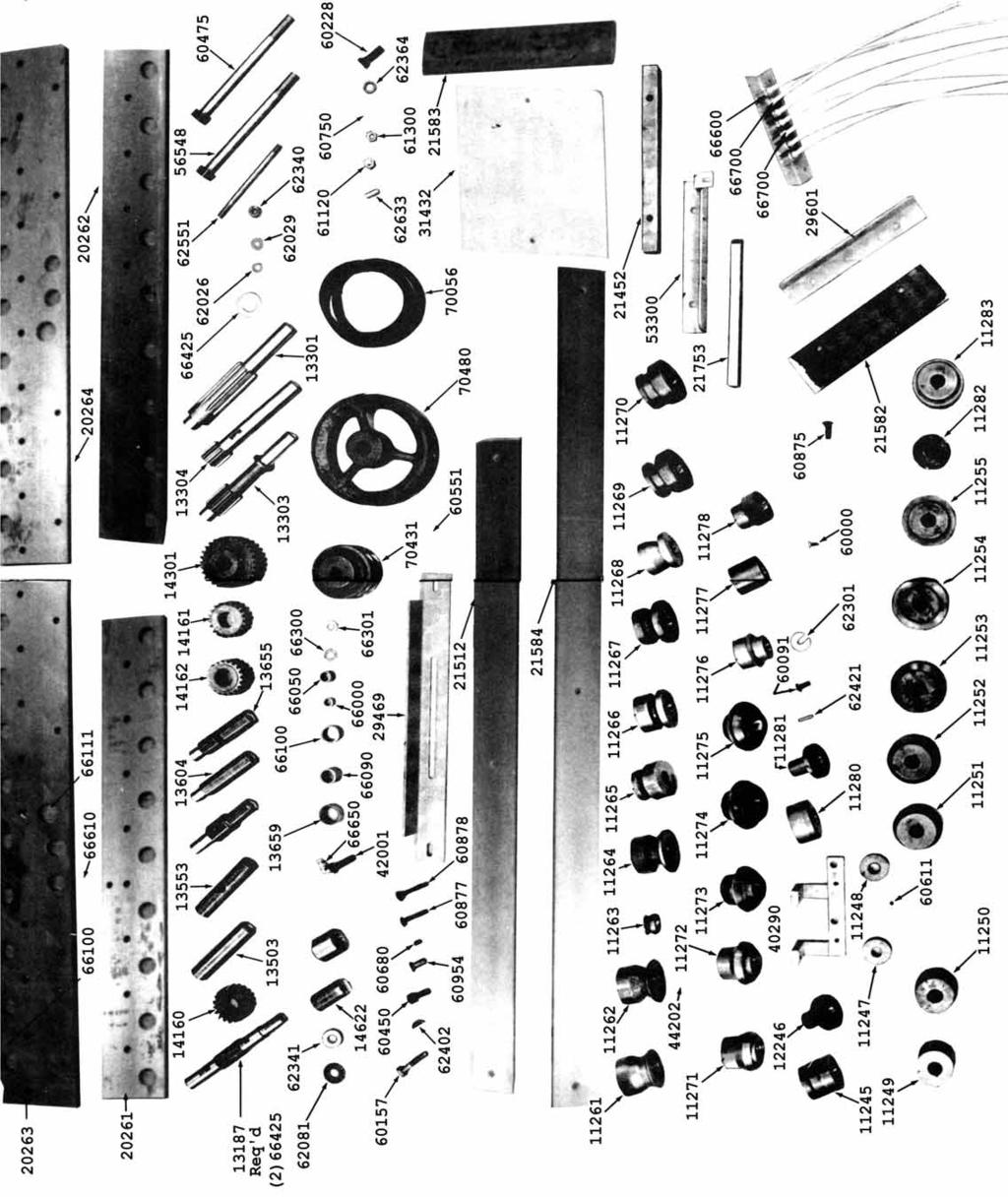
7 PARTS LIST NEW PART DESCRIPTION NO. PIECES PER UNIT NEW PART DESCRIPTION NO. PIECES PER UNIT Lower Front Plate Lower Back Plate Upper Front Plate Upper Back Plate Roll Shaft Drive Gear Plain Spacer Spacer Drilled on Center Main Idler Spacer Idler Spacer Plain Spacer Drilled on Center Idler Main Idler Gear Idler Gear Drive Gear lst Drive Shaft nd Drive Shaft rd Drive Shaft TT Thrust Bearing /8 x.052 Washer /8 x 1/16 Washer /8 Blvl. Washer /8-16 x 6-1/2 Stud Hex. Stud Assembly H.T Hex. Stud Assembly /8 x 3/16 Washer Blvl. Washer Saddle Washers Lube Bolt HJ Torr Bearing B1416 Torr. Bearing B1612 Torr Bearing B1612 OH Torr. Bearing Torr B1012 Torr Bearing NTA 815 Torr TRA Motor Control W49 Heater Element BX Connector 3/ BX Cable H. P BK 40 7/8 Sheave BK 80 H 1 Sheave L 540 Belt /8 x 1 Dwi H.N. Hvy. S.F Jam Nut S.F /4-20 x 1/2 Sq. HSS HT /2 Lock Washer /2-13 x 1-1 /2 HHCS HT /2-13 x 2-1/4 HHCS Woodruff Key /2-13 x 1 SHCS /2-13 x 1 FHSCS /8-16 x 3/8 SSS /-16 x 1-3/4 CB /8-16 x 2 CB Stand Assembly Motor Base /4-20 x 1/2 RHMS Lockformer Logo Cover Assembly Material Support B.L.F Entrance Table Pad Fem Material Support Auxiliary Entrance Table Pad Assembly BLF Tl BLF T Idler Roll 2, Spacer BLF T BLF T BLF T BLF T BLF T BLF T BLF T Entrance Gauge Bar Entrance Hold Down BLF Bl BLF B BLF B BLF B BLF B BLF B BLF B BLF B8 B Exit Gauge Assembly Hold Down Bar Tl Forming Roll T2, 3, 4, 5, 6, Forming Roll Idler Bracket Mach T7 Idler Roll T8 Idler Roll /4-20 x 3/8 SSS T8 Forming Roll T9 Forming Roll /16 Sq. x 7/8 Key /8-16 x 1 HHCS /8-C Washer Bl Forming Roll B2 Forming Roll B3 Forming Roll B4 Forming Roll 1
8 NEW PART DESCRIPTION NO. PIECES PER UNIT B5 Forming Roll B6 Forming Roll Forming Roll B8 Forming Roll B9 Forming Roll Exit Base Plate Exit Gauge Gear Fittings L Hlf. Union Angle Body L Female Coupling Nyla Tubing 4/ Nyla Tubing 3/ /4-20 x 1/2 HHCS /8-16 x 1 C.B Idler Roll Pins Entrance Gauge Grease Fitting Shim Fibre Gear Assembly /16-18 x 3/4 HHCS /16-18 x 1/4 HHCS /4-20 x 1 SHCS /8-16 x 3/4 SHCS /4-20 x 3/8 FHMS x 3/8 RHMS x 7/16 FHMS x 3/16 Drive Screw U. Cad H. N /16-18 H.N. Hvy. S.F /8-16 H.N. Fin /16 x 1/16 Washer /16 Lock Washer Med BX Connector 3/ Rg. Tng. Terminal Back Enclosure Name Plate 1
TK 20 GA. BUTTON LOCK ROLLFORMER
 1 TIN KNOCKER TK 20 GA. BUTTON LOCK ROLLFORMER INSTRUCTIONS & PARTS DIAGRAM TAAG MACHINERY CO. (Master Distributor) 1257-B Activity Dr. Vista, CA 92081 Tel: (800) 640-0746 Fax: (760) 727-9948 Website:
TIN KNOCKER FOURPLEX CLEAT FORMER INSTRUCTIONS & PARTS DIAGRAM
 TIN KNOCKER FOURPLEX CLEAT FORMER INSTRUCTIONS & PARTS DIAGRAM Sheet Metal Equipment Sales Inc. Dean P. O'Connell, President Green Bay, Wisconsin Phone - (90)-66-9966 Fax - (90)-66-9969 Website: www.sheetmetalequip.com
20 Gauge Super-Speed. shoprpmachine
 Operator tor s s manual 20 Gauge Super-Speed 1 WARRANTY Our guarantee on the products we manufacture is limited to repair or replacement without charge, of any part found to be defective in materials or
Visit Our Our Our Web Site at:
 Visit Our Our Our Web Site at: ww w ww w w w w. l o c k f o rr r m e r r r. c o m 711 OGDEN AVENUE, LISLE, ILLINOIS 60532-1399 Phone (630) 964-8000 Fax (630) 964-5685 09-1998 Operator tor s manual 20 Gauge
LockFormer / Auto Glide Power Flanger
 LockFormer / Auto Glide Power Flanger Operating Instructions The operation of the machine is dependent upon proper gauge settings. The heavier materials require a greater spring pressure than the lighter
Lockformer / 5 foot and 10 foot Speednotch
 Lockformer / 5 foot and 10 foot Speednotch INSTALLATION PROCEDURE IMPORTANT: Because of shipping requirements and possible spillage of hydraulic fluid, the unit is tested at Lockformer's plant and the
INSTRUCTIONS & PARTS DIAGRAM Pittsburgh 20 or 22 Gauge with Auto-Guide Mounted. LKF Pittsburgh Gauge
 LKF Pittsburgh 0- Gauge INSTRUCTIONS & PARTS DIAGRAM Pittsburgh 0 or Gauge with Auto-Guide Mounted LKF Pittsburgh 0- Gauge Pittsburgh 0 or Gauge Instructions and Parts Diagram with Auto-Guide Flanger Mounted
 Page 1 of 15 Transmission, Model S5-42 ZF Model S5-42 ZF Disassembly NOTE: For 4x4 and F-Super Duty vehicles, skip to Step 5. 1. Attach the transmission to the Bench Mounted Holding Fixture T57L-500-B
CALIFORNIA TRIMMER MOWER MAINTENANCE MANUAL
 CALIFORNIA TRIMMER MOWER MAINTENANCE MANUAL 2 Table of Contents Section 1: General Information Page Handle Assembly Instructions 4 Maintenance All Models 6 Oil Change Procedures All Models 9 Height Adjustment
LK-24 PITTSBURGH LOCK MODEL 20 O PER A TO R S M A N U A L A PRODUCT OF
 LK-24 PITTSBURGH LOCK MODEL 20 O PER A TO R S M A N U A L A PRODUCT OF VER. INT. LK24-00-CE 03-2011 WARNING THISEQUIPMENTISDESIGNEDTOBEOPERATEDWITHALL COVERSSECUREDINPLACE.OPERATIONWITHOUTTHESE SAFEGUARDSMAYRESULTINCONDITIONSWHICHARE
REMOVAL & INSTALLATION
 REMOVAL & INSTALLATION Removal 1. Center steering wheel. Disconnect negative battery cable. Remove steering coupling shield (if equipped). Disconnect steering shaft at flexible coupling or pot joint. Note
X.L. BAND W/ SPRING ASSIST INSTRUCTION MANUAL
 PARTS LIST X.L. BAND W/ SPRING ASSIST INSTRUCTION MANUAL (2) Bands (1) Handle assembly (2) Side hinge assemblies (1) Left rear hinge assembly (1) Right rear hinge assembly (2) front spring s (2) rear spring
ATLAS TRANSFER CASES CABLE SHIFTER units built after 5/1/12
 KIT CONSISTS OF: No. Qty Part No. Description P.O. Box 247, 4320 Aerotech Center Way PAGE 1 OF 6 Page Rev. Date: 08-01-17 1 1 302051 BASE- TWIN STICK MOUNT 2 1 302060 BOOT- TWIN STICK 3 1 302063 BOOT RING-
F-TDF OPERATOR S MANUAL PRODUCTION PRODUCTS, INC.
 F-TDF OPERATOR S MANUAL PRODUCTION PRODUCTS, INC. CONTENTS 1. SAFETY GUIDELINES... 1 1.1 Safety First... 1 1.2 Safety Precautions Before Starting the Machine... 1 1.3 Safety Precautions While Operating
Transmission Overhaul Procedures-Bench Service
 How to Assemble the Lower Reverse Idler Gear Assembly Special Instructions In 1996 Eaton changed the reverse idler system design. In the nut design, the reverse idler bearing was lubricated through a hole
Maintenance Information
 45528270 Edition 1 June 2007 Barring Motor T480 Series Maintenance Information Save These Instructions WARNING Always wear eye protection when operating or performing maintenance on this Barring Motor.
Operator s Manual TDC-V A PRODUCT OF
 Operator s Manual TDC-V A PRODUCT OF VER. INT. TDC V-02 03-2005 TABLE OF CONTENTS Saftey Guidelines 2 Warranty 3 Saftey Sign-Off Sheet 4-5 Tooling 6 Installation 6 Operation of TDC Joint Profile Rollset
Instruction Manual for HSPA Take-Up Units
 Installation Instruction Manual for HSPA Take-Up Units Warning: To ensure the drive is not unexpectedly started, turn off and lockout the power source before proceeding. Failure to observe these precautions
Differential Ring And Pinion
 SECTION 205-02B: Rear Drive Axle/Differential Ford 8.8-Inch Ring Gear 2009 Mustang Workshop Manual IN-VEHICLE REPAIR Procedure revision date: 01/06/2010 Differential Ring And Pinion Special Tool(s) 2 Jaw
WJ AUTO TRANS. ATLAS SHIFTER
 KIT CONSISTS OF: No. Qty Part No. Description 4320 Aerotech Center Way, Page 1 of 8 1 1 302051 BASE- ATLAS TWIN STICK MOUNT 2 1 302080 STUD BOLT 1/2-13 X 7 B7 3 1 303120 Serrated-Flange Hex Locknut 1/2-13
JEEVES. JEEVES Installation Manual. Installation Manual The Easiest Do-It-Yourself Dumbwaiter on the Market
 1 888-323-8755 www.nwlifts.com JEEVES Installation Manual The Easiest Do-It-Yourself Dumbwaiter on the Market This manual will cover the installation procedure step-by-step. The installation of this dumbwaiter
H.I.T Truck Tire Changer. Parts Identification
 H.I.T. 6000 Truck Tire Changer Parts Identification READ these instructions before placing unit in service KEEP these and other materials delivered with the unit in a binder near the machine for ease of
Assembly Instructions
 Assembly Instructions Part Number Description Model Approx. Assembly Time 99994-0903 Windshield Wiper Kit Mule SX 1 Hour WARNING Improper installation of this accessory could result in an accident causing
1984 Dodge W250 PICKUP
 1984 Dodge W250 PICKUP Submodel: Engine Type: V8 Liters: 5.2 Fuel Delivery: CARB Fuel: GAS Dana 44 MODELS THROUGH 1984 2. Raise and safely support the vehicle, then remove the wheel hub and bearings as
DISASSEMBLY. Transmission. 2. Remove the 4 clutch housing bolts. Separate the clutch housing from the transmission.
 308-03A-1 DISASSEMBLY Transmission 308-03A-1 Special Tool(s) Puller, Bearing 205-D064 (D84L-1123-A) or equivalent Remover/Installer, Front Wheel Hub 204-069 (T81P-1104-C) 2. Remove the 4 clutch housing
Maintenance Information
 Form 16573321 Edition 1 July 2004 Air Grinder Series 61H Maintenance Information Save These Instructions Always wear eye protection when operating or performing maintenance on this tool. Always turn off
LK-20 OPERATOR S MANUAL WITH AUTO-GUIDE POWER FLANGING ATTACHMENT INSTRUCTIONS AND PARTS DIAGRAM PITTSBURGH LOCK MODEL 20 A PRODUCT OF
 LK-20 OPERATOR S MANUAL PITTSBURGH LOCK MODEL 20 WITH AUTO-GUIDE POWER FLANGING ATTACHMENT INSTRUCTIONS AND PARTS DIAGRAM A PRODUCT OF VER. US. LK20-02 11-2005 WARNING THIS EQUIPMENT IS DESIGNED TO BE
Section 13. Tail Rotor Drive. RotorWay International A600 TALON Construction Manual. Section 13. Page A
 RotorWay International Page A Tail Rotor Drive Procedures covered in this section: Install driveshafts and gearboxes; install drive belt and tensioner; fabricate and install tail rotor pitch actuator arms;
Maintenance Information
 16573321 Edition 3 February 2014 Air Grinder Series 61H Maintenance Information Save These Instructions Product Safety Information WARNING Failure to observe the following warnings, and to avoid these
Air Mod-Kit Changing out the 7 poly wheels on the rear of the T78 to 8.5 rubber air tires TRIKKE
 Air Mod-Kit Changing out the 7 poly wheels on the rear of the T78 to 8.5 rubber air tires. T78-CS Air Mod-Kit Disclaimer This document was written by Trikke Tampa. It s of our own opinion and example of
INSTALL MANUAL. FOR ON LINE ORDERING- E Commerce Visit Our Website
 INSTALL MANUAL FOR ON LINE ORDERING- E Commerce Visit Our Website WWW.PRESSUREGUARD.COM Contact Information Technical Support: Chris@pressureguard.com Sales Support: Sales@pressureguard.com By Phone: 615-227-6024
INSTALLATION INSTRUCTIONS CHEVY C-10 4-Link Rear End
 INSTALLATION INSTRUCTIONS 73-87 CHEVY C-10 4-Link Rear End Please read these instructions completely before starting your installation. Assemble suspension on vehicle before powder-coating to ensure proper
Mulching and Finishing Mowers MP and FP
 Mulching and Finishing Mowers MP and FP Parts Manual Locke Turf 0 Highway E, Opp, Alabama, () -00 Transport Wheel, Tire & Spindle MP and FP ALPHABETICAL INDEX CONTENTS PAGE 00 Hydraulic Cylinder (Rear)
Chevy Nova Pro-Touring Front Suspension Installation Instructions
 1962-1967 Chevy Nova Pro-Touring Front Suspension Installation Instructions 1-800-984-6259 www.totalcostinvolved.com 1 Pro-Touring Clip A-Arm Assembly Sway Bar Assembly Fender Panel Kit 8 7/16-20 * 1 ¼
H.I.T Truck Tire Changer. Parts Identification
 H.I.T. 6000 Truck Tire Changer READ these instructions before placing unit in service KEEP these and other materials delivered with the unit in a binder near the machine for ease of reference by supervisors
1988 Chevrolet Pickup V SUSPENSION - FRONT (4WD)' 'Front Suspension - "V" Series 1988 SUSPENSION - FRONT (4WD) Front Suspension - "V" Series
' 'Front Suspension - V Series 1988 SUSPENSION - FRONT (4WD) Front Suspension - V Series") 1988 SUSPENSION - FRONT (4WD) Front Suspension - "V" Series DESCRIPTION NOTE: Vehicle serial numbers used in this article has been abbreviated for common reference to Chevrolet and GMC models. Chevrolet
1988 SUSPENSION - FRONT (4WD) Front Suspension - "V" Series DESCRIPTION NOTE: Vehicle serial numbers used in this article has been abbreviated for common reference to Chevrolet and GMC models. Chevrolet
2001 Dodge RAM 3500 PICKUP
 1 of 76 9/14/2012 7:02 PM 2001 Dodge RAM 3500 PICKUP Submodel: Engine Type: L6 Liters: 5.9 Fuel Delivery: FI Fuel: DIESEL Subarticles MANUAL- NV3500 - DISASSEMBLY MANUAL- NV3500 - DISASSEMBLY MANUAL -
1.6L 4-CYL - VIN [E]
![1.6L 4-CYL - VIN [E]](/thumbs/81/84172348.jpg "1.6L 4-CYL - VIN [E]") 1.6L 4-CYL - VIN [E] 1993 Nissan Sentra 1993 NISSAN ENGINES 1.6L 4-Cylinder NX, Sentra * PLEASE READ THIS FIRST * NOTE: For engine repair procedures not covered in this article, see ENGINE OVERHAUL PROCEDURES
1.6L 4-CYL - VIN [E] 1993 Nissan Sentra 1993 NISSAN ENGINES 1.6L 4-Cylinder NX, Sentra * PLEASE READ THIS FIRST * NOTE: For engine repair procedures not covered in this article, see ENGINE OVERHAUL PROCEDURES
Lifecycle Upright Bikes LC95, LC91, LC85, C9, C7, 95Ce, 95Ci, 93Ci, and 90C How To... Replace the Intermediate Pulley Shaft and Bearings
 How To... Replace the Pulley Shaft and s Special Service Tools: Service Tool Kit Part Number: ToolKit 1. Remove the side covers. Refer to, How To Remove Pedals, Pedal Levers, and Side Shrouds. Main Drive
DRIVE AXLE Volvo 960 DESCRIPTION & OPERATION AXLE IDENTIFICATION DRIVE AXLES Volvo Differentials & Axle Shafts
 DRIVE AXLE 1994 Volvo 960 1994 DRIVE AXLES Volvo Differentials & Axle Shafts 960 DESCRIPTION & OPERATION All 960 station wagon models use type 1041 rear axle assembly. All 960 4-door models use type 1045
600 SERIES STANDARD DUTY STRAIGHT TRACK INSTALLATION INSTRUCTIONS
 600 SERIES STANDARD DUTY STRAIGHT TRACK INSTALLATION INSTRUCTIONS PLEASE READ INSTRUCTIONS THOROUGHLY BEFORE BEGINNING. A. BI-PARTING TRAVEL 1. Before raising track into position, determine location of
INSTALLATION & OWNER S MANUAL
 Rev. B, p. 1 of 25 INSTALLATION & OWNER S MANUAL POLARIS RANGER RCS (for models XP or HD) (for model years 2009-) cab without doors kit (p/n 1POLRCWD) cab with doors kit (p/n 1POLRC) doors only kit (p/n
Installation Instructions Capacity 10,000 lbs. (100 Series Lift)
") Installation Instructions Capacity 10,000 lbs. (100 Series Lift) IMPORTANT Reference ANSI/ALI ALIS, Safety Requirements for Installation and Service of Automotive Lifts before installing lift. OPERATING
Installation Instructions Capacity 10,000 lbs. (100 Series Lift) IMPORTANT Reference ANSI/ALI ALIS, Safety Requirements for Installation and Service of Automotive Lifts before installing lift. OPERATING
PARTS ORDERING INFORMATION
 RP-268 REPAIR PARTS FOR VE268 Roll Grooving Tool PARTS ORDERING INFORMATION When ordering parts the following information is necessary for the Victaulic Tool Company to promptly process the order and send
A B C D E F. Tools Required (supplied by others)
") Page 1 of 17 Parts List Below Deck Automatic Retractable Security Cover Kit (1) Tube End Bearing Plate (A) (1) Rope Reel and Cover Drum Motor Assembly (B) (1) Cover Drum (1) Pulley Support Channel (2)
Page 1 of 17 Parts List Below Deck Automatic Retractable Security Cover Kit (1) Tube End Bearing Plate (A) (1) Rope Reel and Cover Drum Motor Assembly (B) (1) Cover Drum (1) Pulley Support Channel (2)
DODGE SuperRail Mounting Kit #0848
 DODGE SuperRail Mounting Kit #0848 #1200 Super 5 th (16K) #0800 Super 5 th (20.5K) Gross Trailer Weight (Maximum) Vertical Load Weight (Max. Pin Weight) 16,000 lbs. 4,000 lbs. Gross Trailer Weight (Maximum)
Bearing Race Service Kit
 0907 Safety Warning Read all instructions and safety warnings prior to operation. Failure to do so could result in equipment damage, personal injury or even death. CAUTION: USE REPLACEMENT PARTS AND ACCESSORIES
POWER STEERING PUMP REBUILDING SPK101 Read instructions completely before removal & disassembly
 POWER STEERING PUMP REBUILDING SPK101 Read instructions completely before removal & disassembly DISASSEMBLY: 1. Remove pump from car and allow to drain. 2. Remove pulley from front of pump. This requires
Output 0.9 H.P. (675 W) 9000 to R.P.M (11000rpm is standard)
 9000 to R.P.M (11000rpm is standard)") HENRY TOOLS Industrial Airtools at Work General Safety and Maintenance Manual COLLET SPINDLE SHOWN Model Number Exhaust Direction Throttle Type 44RAE Side (L) Lever or (K) Safety Lever Speed 9000 to 11000
HENRY TOOLS Industrial Airtools at Work General Safety and Maintenance Manual COLLET SPINDLE SHOWN Model Number Exhaust Direction Throttle Type 44RAE Side (L) Lever or (K) Safety Lever Speed 9000 to 11000
LIFTING MECHANISM PART NO SRM 965
 LIFTING MECHANISM B60Z [A230]; B80Z [A233]; C60Z [A478]; C80Z [A479]; W60Z [A231]; W65Z [A229]; W80Z [A234]; B60Z AC [B230]; B80Z AC [B233]; C60Z AC [B478]; C80Z AC [B479] PART NO. 1500202 4000 SRM 965
USE THE PARTS LIST BELOW TO MAKE SURE YOUR KIT IS COMPLETE BEFORE INSTALLATION. IF ANY PIECES ARE MISSING, PLEASE CONTACT:
 1962-1967 Chevy Nova Pro-Touring Front Suspension Installation Instructions Tech line: 1-855-693-1259 www.totalcostinvolved.com Read and understand these instructions before starting any work! USE THE
BS 2/K Transverse Conveyor
 Modular Transfer Systems BS 2/K Transverse Conveyor for TSplus Conveyors Installation and Maintenance Guide Publication Number: 8981 500 207 11/00 2 Table of Contents INTRODUCTION... 3 TECHNICAL DATA...
H.I.T Truck Tire Changer
 u H..T. 6000 Truck Tire Changer READ these instructions before placing unit in service KEEP these and other materials delivered with the unit in a binder near the machine for ease of reference by supervisors
INSTALLATION INSTRUCTIONS
 INSTALLATION INSTRUCTIONS --1075 North Ave. Sanger, CA 93657-3539 local: 559-875-0222 fax: 559-876-2259 toll free: 800-445-3767-- 2505 Lowering Spindle Assembly Installation Instructions ½ TON SILVERADO
INSTALLATION INSTRUCTIONS Air Spring Kit Ford F-250/350 Single Wheel 2WD IMPORTANT NOTES
 INSTALLATION INSTRUCTIONS 6107 Air Spring Kit 1999+ Ford F-250/350 Single Wheel 2WD Thank you for purchasing a quality Hellwig Product. PLEASE READ THIS INSTRUCTION SHEET COMPLETELY BEFORE STARTING YOUR
Installation Procedures
 For the precision ball and roller bearings supplied by MRC Bearings, skill and cleanliness while handling, mounting and dismounting are necessary to ensure satisfactory bearing performance. As precision
PARTS LISTING a WR
 7 CRT 3 2.1 PARTS LISTING 54140066a WR 02-1- HANDLE ASSEMBLY 1 711100 Screw, Pan Hd. #10-24 UNC 2 53212656 Panel, Control 3 532104164 Tie, Cable 4 53212477 Grip, Handle 5 5321247 Clip, Hairpin 6 5320132
WALK-BEHIND TROWEL B436 B436E B436SD. Effective Serial Numbers: , , , and higher.
 WALK-BEHIND TROWEL B436 B436E B436SD Effective Serial Numbers: 127458, 127543, 127782, 127834 and higher. Doc. # PB-B09001 Orig. Rel. - 05-2010 Curr. Rev. - 10 Rev. Date - 06-2014 Bartell Morrison (USA)
Installation Guide Current Ford F-250 & Ford F-350 Super Duty. Product Code: 109 & 119
 Installation Guide 2008 - Current Ford F-250 & Ford F-350 Super Duty Product Code: 109 & 119 September 1, 2012 Tools Needed Components Included 3/8" Drill P2 Tip #2 Philips Screwdriver 1/2" Drill Bit Hinged
vertical cradle lifts installation instructions
 vertical cradle lifts installation instructions models 7,000 lb. thru 45,000 lb. important: read this manual before beginning installation of cradle lift. 5560 Ulmerton Road Clearwater, Florida 33760 1.800.878.5560
Technical Support Line: (952) Hanover Ave. Lakeville, MN
 Hanover Ave. Lakeville, MN") Technical Support Line: (952) 985-5675 Email: Sales@QA1.net 21730 Hanover Ave. Lakeville, MN 55044 www.qa1.net INSTALLATION INSTRUCTIONS QA1 1967-1979 Mopar A-Body Rear 6 link Conversion System QA1 p/n
Technical Support Line: (952) 985-5675 Email: Sales@QA1.net 21730 Hanover Ave. Lakeville, MN 55044 www.qa1.net INSTALLATION INSTRUCTIONS QA1 1967-1979 Mopar A-Body Rear 6 link Conversion System QA1 p/n
I Illustrated Parts List CRT B. Tiller. Repair Parts Manual
 Illustrated Parts List 15-12 I502012 CRT 1 54001152B Repair Parts Manual Tiller HANDLE ASSEMBLY 1 711100 Screw, Pan Hd. #10-24 UNC 2 53212656 Panel, Control 3 532104164 Tie, Cable 4 53212477 Grip, Handle
1209A GM B-BODY Double Adjustable Trailing Arms
 1209A 78-96 GM B-BODY Double Adjustable Trailing Arms Warning: This installation should be performed by a trained professional. Tools Required for this Installation - 4 post lift or alignment rack preferable
Fig Variable Speed Valve Parts
 5 DISASSEMBLY OF VARIABLE SPEED CONTROL VALVE (Seal Replacement with Control Valve in the Bobcat). Remove seat and seat plate (Fig. ).. Remove variable speed control lever linkage rod. 3. Remove temperature
Procedure Replacing a Cover
 Procedure 7.1 - Replacing a Cover Cover Removal 1. Remove two screws, one each side, from the front of the top cover. Remove the top cover. See Diagram 7.1. Diagram 7.1 - RBK 815 Covers Top Cover Left
Service Manual. Example Part Number. Motor Supplier. Motor Number. Ratio. Bail Boss. Input. Model. Shaft. Cover
 Service Manual 0 Series Digger models Example Part Number 0 7 f 0 C 7 Model Ratio Shaft Bail Boss Motor Supplier Motor Number Cover Input This service manual is effective: S/N: 0000 to current date: 0
Maintenance Information
 04581245 Edition 2 May 2014 Air Grinder, Die Grinder and Sander Series G2 (Angle) Maintenance Information Save These Instructions Product Safety Information WARNING Failure to observe the following warnings,
HYDRAULIC VALVE KIT McCORMICK MC90, MC100, & MC115 TRACTORS
 ASSEMBLY MANUAL 2-7367 Keep With Operator s Manual HYDRAULIC VALVE KIT McCORMICK MC90, MC100, & MC115 TRACTORS Note: Requires McCormick power beyond manifold and joystick to complete. Figure 2 VALVE INSTALLATION
Siderolling Tarp Systems Under 9 6 Wide
 Load Loc Select Maximizer Grain Carts Grain Bagger Siderolling Tarp Systems Under 9 6 Wide CRANK STYLE INSTALLATION INSTRUCTIONS MICHEL S INDUSTRIES, LTD. P.O. BOX 119 ST. GREGOR, SK. S0K 3X0 PH:306.366.2184
4405-RA 4405-R 4405-RA 4405-R S
 ACCESSORIES Page 34 Master Parts Breakdowns Updated Feb. 1st 2006 Master Parts Breakdowns Updated Feb. 1st 2006 Page 35 This tool is designed to operate on 90 psig (6.2 bar) maximum air pressure with 1/4
Premium Dry Freight (Plywood) Door Installation REFERENCE FIGURE 1
 Door Installation REFERENCE FIGURE 1") Premium Dry Freight (Plywood) Door Installation A Premium door can be identified as usually having a two-spring balancer, 2 diameter (nominal) rollers, and end hinges with removable covers. If your Whiting
Premium Dry Freight (Plywood) Door Installation A Premium door can be identified as usually having a two-spring balancer, 2 diameter (nominal) rollers, and end hinges with removable covers. If your Whiting
FA SERIES FORD AUTOMATIC PTO
 FA SERIES FORD AUTOMATIC PTO PARTS LIST AND SERVICE MANUAL Muncie Power Products, Inc. FA SERIES PTO EXPLODED 18 Ft.Lb. 5 Ft.Lb. 18-25 Ft.Lb. Gasket Ford Supplied 44 Reuse Gasket Found on Opening or Order
ATLAS TRANSFER CASES CABLE SHIFTER units built before 4/30/12
 Paso Robles, CA 93447 PAGE 1 OF 5 Telephone: (800) 350-2223 Fax: (805) 238-4201 Page Rev. Date: 05-12-15 KIT CONSISTS OF: No. Qty Part No. Description 1. 1 302051 TWIN STICK BASE MOUNT 2. 1 302060 TWIN
Instruction Manual for PTI Split Block Bearing Units For SAF, SDAF, SN, SNG, SNHF, S3000K & SD Series Housings
 Instruction Manual for PTI Split Block Bearing Units For SAF, SDAF, SN, SNG, SNHF, S3000K & SD Series Housings Installation SDAF SD & S3000 SAF Warning: To ensure that the drive is not unexpectedly started,
Fisher 657 Diaphragm Actuator Sizes and 87
 Instruction Manual 657 Actuator (30-70 and 87) Fisher 657 Diaphragm Actuator Sizes 30 70 and 87 Contents Introduction... 1 Scope of Manual... 1 Description... 2 Specifications... 2 Installation... 3 Mounting
INSTALLATION GUIDE. JK Rear bumper & tire carrier. AEV30105AC Last Updated: 10/11/16 US PATENT: D642,502 ; D
 AEV30105AC Last Updated: 10/11/16 JK Rear bumper & tire carrier US PATENT: D642,502 ; D633.024 INSTALLATION GUIDE PLEASE READ BEFORE YOU START TO GUARANTEE A QUALITY INSTALLATION, WE RECOMMEND READING
Valtek Auxiliary Handwheels and Limit Stops
 Valtek Auxiliary s and Limit Stops Table of Contents Page 1 General information 2 Installation 2 Side-mounted handwheels, size 25 and 50 (linear actuators) 3 Side-mounted handwheels, size 100 and 200 (linear
STEERING COLUMN - TILT
 STEERING COLUMN - TILT 1993 Toyota Celica 1993 STEERING Toyota - Steering Columns - Tilt Wheel Celica DESCRIPTION & OPERATION Tilt steering wheels incorporate an upper steering shaft, attached by a "U"
HYDROBURST HB3038, HB5058, HB80, HB125
 TM HYDROBURST HB3038, HB5058, HB80, HB125 Parts Manual HYDROBURST HB3038, HB5058, HB80 & HB125 s/n Part No. PM1251 INTRODUCTION HOW TO USE THE MANUAL This manual contains illustrations and parts list of
FORD SuperRail Mounting Kit #3361
 FORD SuperRail Mounting Kit #3361 #4100 SuperGlide (16K) #4400 SuperGlide (20K) Gross Trailer Weight (Maximum) Vertical Load Weight (Max. Pin Weight) 16,000 lbs. 4,000 lbs. Gross Trailer Weight (Maximum)
NOTE: DISCONNECT MAIN POWER LOCK OUT AND TAG BEFORE PERFORMING ANY PROCEDURES IN THIS SECTION.
 M E C H A N I C A L S E T U P & A D J U S T M E N T S NOTE: DISCONNECT MAIN POWER LOCK OUT AND TAG BEFORE PERFORMING ANY PROCEDURES IN THIS SECTION. NOTE: All adjustments should be made with the sealer
Maintenance Information
 16575128 Edition 2 May 2014 Air Grinder, Sander or Polisher 77A Series Maintenance Information Save These Instructions Product Safety Information Failure to observe the following warnings, and to avoid
SERVICE MANUAL 375 SERIES DIGGER MODELS
 SERVICE MANUAL 75 SERIES DIGGER MODELS Example Part Number 75 F 0 BP Model Ratio Shaft Bail Boss Motor Supplier Motor Number Back Spin Protection THIS SERVICE MANUAL IS EFFECTIVE: S/N: 00 TO CURRENT DATE:
Read these instructions thoroughly before attempting to install this option.
 Rewind Option Kit Installation Instructions This kit includes the parts and documentation necessary to install the Media Rewind option into the following printers: 0XiIIIPlus, 0 dpi 0XiIIIPlus, 00 dpi
Opening Quality Doors Around The World. Installation Instructions Bi-Parting Freight Doors - Q Style (Power and Manual)
") Opening Quality Doors Around The World www.couriondoors.com Installation Instructions Bi-Parting Freight Doors - Q Style (Power and Manual) Table of Contents For Immediate Help Call 1-800-533-5760 Q Style
Opening Quality Doors Around The World www.couriondoors.com Installation Instructions Bi-Parting Freight Doors - Q Style (Power and Manual) Table of Contents For Immediate Help Call 1-800-533-5760 Q Style
INSTALLATION INSTRUCTIONS Air Spring Kit Dodge WD IMPORTANT NOTES
 INSTALLATION INSTRUCTIONS 6211 Air Spring Kit 2003+ Dodge 1500 4WD Thank you for purchasing a quality Hellwig Product. PLEASE READ THIS INSTRUCTION SHEET COMPLETELY BEFORE STARTING YOUR INSTALLATION IMPORTANT
TABLE OF CONTENTS CHAPTER 1.. CHAPTER 2.. CHAPTER 3.. CHAPTER 4.. CHAPTER 5.. CHAPTER 6.. CHAPTER 7.. CHAPTER 8.. CHAPTER 9..
 CHAPTER 1.. CHAPTER 2.. CHAPTER 3.. CHAPTER 4.. CHAPTER 5.. CHAPTER 6.. CHAPTER 7.. CHAPTER 8.. CHAPTER 9.. CHAPTER 10... CHAPTER 11... CHAPTER 12... TABLE OF CONTENTS SPECIFICATIONS:...1 PRECAUTIONS:...2
6/17 HJ26077 Rev 12. US Pat. 7,506,886 US Pat. 7,753,392 CA Pat. 2,576,427 AS Pat PAGE 1
 6/17 HJ26077 Rev 12 US Pat. 7,506,886 US Pat. 7,753,392 CA Pat. 2,576,427 AS Pat. 2007200421 PAGE 1 WARRANTY POLICY, OPERATOR MANUALS & REGISTRATION Go online to www.demco-products.com to review Demco
WARNING WARNING CAUTION
 IV. REPAIR T his chapter provides instructions for the major systems adjustment, repair, and replacement of the RICON Mirage F9A Series Transit Use Wheelchair and Standee Lift. A. GENERAL SAFETY PRECAUTIONS
Required tools General hand tools 21/64" drill bit Torque wrench Threadlocker Center punch
 Slipper Spring Kit (part numbers 2560, 2570 and 2580) Item Qty Part number Description 1... 8... 350054-50...3/8-16 x 1" grade 8 self-tapping screw 2... 4... 350084-00...7/16-14 x 4" grade 5 3... 6...
SUBJECT: INTEGRATED FUEL SYSTEM (IFS) UNIT PUMP SERVICE
 UNIT PUMP SERVICE") DATE: July 30, 2010 SERVICE BULLETIN SUPERSEDES: S.B. 560 dated November 22, 2008 NO: 560R1 SUBJECT: INTEGRATED FUEL SYSTEM (IFS) UNIT PUMP SERVICE RELATED PUBLICATIONS: IFS OPERATION AND INSTRUCTION MANUAL
DATE: July 30, 2010 SERVICE BULLETIN SUPERSEDES: S.B. 560 dated November 22, 2008 NO: 560R1 SUBJECT: INTEGRATED FUEL SYSTEM (IFS) UNIT PUMP SERVICE RELATED PUBLICATIONS: IFS OPERATION AND INSTRUCTION MANUAL
Model 802 Center Mount Adapter For New Holland 9030 & TV140 Bi-Directional Tractors PARTS CATALOG
 Model 802 Center Mount Adapter For New Holland 9030 & TV140 Bi-Directional Tractors 1 PARTS CATALOG TABLE OF CONTENTS Frame & Tractor Linkage...2,3 Header Linkage & Float Group...4,5 Header Drive Hydraulics
Agri-Fab OWNERS MANUAL. Model No " ROUGH CUT TRAILMOWER. CAUTION: Read Rules for Safe Operation and Instructions Carefully
 Agri-Fab OWNERS MANUAL Model No. 45-0362 CAUTION: Read Rules for Safe Operation and Instructions Carefully Safety Assembly Operation Maintenance Parts 42" ROUGH CUT TRAILMOWER NOTE: Your mower deck will
Z-Gate Universal Shifter
 Installation Instructions Z-Gate Universal Shifter Fits: GM, Ford, Lincoln and Chrysler Transmissions See Application Guide for Specific Applications Part #80681 Rev 06/01/2018 WORK SAFELY! For maximum
IN-VEHICLE REPAIR. Differential Bearings. Rear Drive Axle/Differential Ford 7.5-Inch Ring Gear. Special Tool(s)
") 205-02A-1 IN-VEHICLE REPAIR Differential Bearings Special Tool(s) Protector, Drive Pinion Thread 205-460 Special Tool(s) Installer, Differential Shim 205-220 (T85L-4067-AH) 205-02A-1 2-Jaw Puller 205-D072
205-02A-1 IN-VEHICLE REPAIR Differential Bearings Special Tool(s) Protector, Drive Pinion Thread 205-460 Special Tool(s) Installer, Differential Shim 205-220 (T85L-4067-AH) 205-02A-1 2-Jaw Puller 205-D072
INSTALLATION, MAINTENANCE, & SAFETY INSTRUCTIONS
 Tarpaulin Systems Flip -N- Go / Quick Mount Flip -N- Go System INSTALLATION, MAINTENANCE, & SAFETY INSTRUCTIONS (800) CRAMARO (800) 272-6276 Plants In: Delaware, Florida, Massachusetts, Nevada, Ohio Install
PART# Tri-Valve Exhaust For SL 17 A/B, 17 K, KM 37 & KMB 18/28 Band Masks
 Tools needed: Medium size flat blade screwdriver PART# 525-752 Tri-Valve Exhaust For SL 17 A/B, 17 K, KM 37 & KMB 18/28 Band Masks Inch Pound Torque screwdriver with medium size flat blade Small cutting
INSTALLATION INSTRUCTIONS 88029
 INSTALLATION INSTRUCTIONS 88029 FOR SUSPENSION SYSTEMS RS6503: JEEP WRANGLER (TJ) READ ALL INSTRUCTIONS THOROUGHLY FROM START TO FINISH BEFORE BEGINNING INSTALLATION REV F IMPORTANT NOTES! WARNING: This
Start-up and Operation
 Start-up and Operation NEVER FORGET THAT ANY MACHINE CAN BE VERY DANGEROUS WHEN NOT OPERATED CORRECTLY AND SAFELY. ALWAYS VISUALLY CHECK TO MAKE SURE THAT ALL PERSONS ARE CLEAR BEFORE TURNING ON ANY CONTROLS.
Assembly Instructions
 Assembly Instructions Part Number Description Model Approx. Assembly Time 99994-049 Cab Enclosure MULE SX 3-4 Hours WARNING Improper installation of this accessory could result in an accident causing serious