LK-24 PITTSBURGH LOCK MODEL 20 O PER A TO R S M A N U A L A PRODUCT OF
|
|
|
- Vivien Houston
- 6 years ago
- Views:
Transcription

1 LK-24 PITTSBURGH LOCK MODEL 20 O PER A TO R S M A N U A L A PRODUCT OF VER. INT. LK24-00-CE
2 WARNING THISEQUIPMENTISDESIGNEDTOBEOPERATEDWITHALL COVERSSECUREDINPLACE.OPERATIONWITHOUTTHESE SAFEGUARDSMAYRESULTINCONDITIONSWHICHARE HAZARDOUSTOTHEOPERATORANDOBSERVERS. SAFETYGUIDELINES Beforeoperatingthemachine,studyandfollowthesafetyprecautionsinthissection. Theseprecautionsareintendedtopreventinjurytoyouandyourfellowworkers.They cannot,however,coverallpossiblesituations.therefore,exerciseextreme CAUTIONanduseCOMMONSENSEbeforeperforminganyprocedureoroperation. SafetyPrecautionsBEFOREStartingTheMachine(s) Only one person should control the machine(s). Never allow anyone to operate the controls while you are operating or working on this equipment. In addition to disconnecting power alwaysuse lockoutsandtagouts to prevent accidental start-up when performing maintenance procedures. Keep your hands away from internal workings of the machinery when starting, running or stopping. Keep your work area clean. Remove all scrap, oil spills, rags, tools and other loose items that could cause you to slip, trip and fall. When cleaning the machine or any of its components, do not use toxic or flamable substances. Do not perform any cleaning while the equipment is running. Never override or disable any safety switch or safety interlock. If so equipped, make sure that hydraulic and pneumatic pressures are at specified levels before operating this equipment. Donotoperatetherollformerunlessallcoversandguardsareinplace. Be sure that this Instruction Manual is kept near the machine so the operator can refer to it when necessary. Keep this equipment properly maintained. Always turn off power to the machine(s) at the main disconnect before performing any maintenance or adjustments so accidental start-up or electrocution cannot occur. 01
3 SafetyPrecautionsWHILE OperatingTheMachine(s) Never leave the work area while the equipment is in operation. Never leave the machine unattended while it is under power or in operation. Always be alert while operating machinery. Be alert for loose, worn or broken parts. Do not attempt to operate any machinery with such parts present or if the machinery is making unusual noises or actions. Avoid skin contact, prolonged breathing, or eye exposure to any stock lubrication fluid being used. Be aware of the locations of the PowerOff or EmergencyStop button in case of an emergency. Besureallguardsandcoversareinplace. Continually observe the rollforming process and related equipment. If any unusual condition develops, immediately stop and inspect the machine. Protect yourself! Wear safety glasses. Do not wear loose clothing, neckties, or jewelry. If long sleeves must be worn, avoid loose cuffs and buttons. Tie back and contain long hair. Never adjust any roll feature or perform work near the rolls, gears or power take off while they are running. General If any pneumatic or hydraulic feature is used, disconnect the main supply and exhaust pressure and bleed the lines to prevent cycling on retained pressure. Always shut off the power at the main disconnect switch before entering the electrical control box. Do not use compressed air to clean the machines. Air pressure may drive dirt and small chips into the machine(s) bearing surfaces or cause bodily injury. IMPORTANT Theinformationcontainedhereinistobeuseasageneralguideonly. ForfurthersafeyinformationobtainandreadtheANSIbulletinentitled: ANSIB RollformingandRoll-BendingMachinessafety RequirementsforConstruction,CareandUse. CONTACT:AmericanNationalStandardsInstitute 11West42ndStreet NewYork,NewYork
4 WARRANTY Ourwarrantyontheproductswemanufactureislimitedtorepairorreplacementwithoutcharge, ofanypartfoundtobedefectiveinmaterialsorworkmanship.thiswarrantyisforaperiodof oneyear(unlessotherwisespecified)fromthedateofshipmentfromourfactory,forall mechanicalfeaturesofthemachineexceptpurchasedcomponentsthatcarrythewarrantyof theoriginalmanufacturer. Thiswarrantyisconditionedonproperinstallation,maintenanceanduseoftheequipment.The warrantywillbevoidiftheequipmentissubjectedtomisuseorabusedorifusedbeyondthe standardsinthismanual,includingmaterialdimensionsandgauge. WarrantypartsandcomponentswillbeshippedfreightcollectfromFORMTEK.Ifthedefective parthasnotbeenreturnedtoformtekwithin15workingdaysafterreceivingthereplacement part,yourcompanywillberesponsibleforthecostofreplacement. Thewarrantyprovidedinthisclauseisinlieuofallotherwarranties,expressorimplied,arising bylaworotherwise,includingtheimpliedwarrantiesofmerchantabilityandfitnessforaparticular purposewhichareherebydisclaimedbyformtekandexcludedfromthisagreement.this warrantyshallnotbemodifiedforanyreason.innoeventshallformtekbeliablefor consequentialorincidentaldamages,includingthecostofassemblyordisassembly,lost productionorpersonalinjury.! CAUTION To provide clarity to points in question the illustrations and photos appearing in this manual are shown with covers and guards removed. NEVER OPERATE THIS EQUIPMENT UNLESS ALL COVERS AND GUARDS ARE IN PLACE. Theinformationinthisdocumenthasbeenreviewedandisbelievedtobecompleteandaccurate. Noresponsibilityisassumedforminorinaccuraciesorcontentnotaddressedinthismanual. Furthermore,FORMTEKreservestherighttomakechangestoanyproductsherein,atanytime,to improvereliability,function,ordesign.formtekdoesnotassumeanyliabilitiesarisingoutofany useofanyproductdescribedherein,nordoesitconveyanylicenseunderitstradesecretsor patentrightsnortherightsofothers. 03
5 SAFETY FIRST Common sense and extreme care must be used at all times during the operation and maintenance of this equipment. It is important that ALL personnel who will operate, maintain, or supervise the use of this equipment, read and understand the sections of this manual concerning SAFETY and the OPERATION of the equipment. The equipment described in this manual was designed and manufactured for a specific function. It should not be used for any other purpose or outside of the design specifications as this may result in damage to the equipment and/or injury to the operator. Modifications or additions to this equipment should not be made. Any such modifications or additions will void the warranty and may subject the operater to injury. Replacement and maintenance parts must be purchased from FORMTEK or the component original equipment manufacturer. Use of other parts may result in unsafe operation or failure of the machinery. If there is a question to the suitability of a part, proper personnel FORMTEK should be consulted. Ingeneral,everypieceofequipmentmustbetreatedwithextremecare.Whileoperatingormaintaining thisequipment,eachindividualmustbeawareoftheirownsafetyaswellasthesafetyofallbystanders. SAFETY SIGN-OFF SHEET It is the employer s responsibility to instruct all persons who may come in contact with this equipment on the safe operation and maintenance of this equipment. If a language barrier or other restriction limits understanding, this manual can be read to the individual with appropriate follow up questions to verify understanding. Have each individual sign below only after demonstrating their understanding of the safety practices described in this manual. I verify that I have read and understand the safety and operation sections for this equipment: NAME DATE NAME DATE 04

6 SAFETYGUIDELINES You are NOT ready to operate this equipment if you have not read and understood all of the safety information in this manual.! WARNING: Do not wear loose clothing, neckties, improper gloves, or jewelry while operating this machine. If long sleeves must be worn, avoid loose cuffs or buttons, Tie back or contain long hair. Wear proper gloves to prevent lacerations caused by sharp edges of stock as it travels through the forming operation. Never operate this equipment unless all covers and guards are properly installed. Be alert for loose, worn, or broken parts. Never operate this equipment unless it is in good working condition. As the stock enters the guides and feeds into the rolls, a pinch point is created as the stock advances. Keep hands clear of area and all pinch points. Always disconnect the main power supply power and install lock outs using a lockout / tagout procedure when making adjustments or repairs. When transporting, take into consideration that the machine is top heavy and may suddenly tip over. The machine is designed for fixed installations and are not intended for portability. Rememberthattheinformationcontainedinthismanualisonlyaportionofanadequate trainingprogram.itmustbecoupledwithspecificinstructionsforyourapplicationalong withfullinformationofnationalandlocalsafetyregulationsthatmayapply. SOUNDPRESSUREINFORMATION TheLockformerRollformerdescribedinthismanualhasbeentestedfornoiseDBlevels. Atnormaloperatingdistancethemachineshouldbenomorethen75DB. YEAROFMANUFACTURE 05
7 INSTALLATION Provide a clean, flat, well lighted installation site. Level the machine and anchor it to the floor. Inspect the gears and drive assembly, and remove any debris that may have accumulated during shipping. ELECTRICALS Standard Electrical: 2HP (1.5KW) 110 Volts 1 phase, grounded power supply. Provide a sufficient 110V receptacle at the point of operation. If a 3 phase motor is ordered install the power supply in compliance with national electrical codes. For further information contact a certified electrician or Lockformer service dept. (Contact information at or tel# ) CAPACITY Maximum 0.6mm thickness (24 Gauge) black iron mild steel and Galvanized steel. MATERIAL ALLOWANCE: = 25mm, 1 (1) 25mm (1 ), female PITTSBURGH (2) 6mm (1/4 )90 degree (MALE) Total amount of material (25mm Female PITTSBURGH + 6mm MALE)=31mm. (1 Female PITTSBURGH + 1/4 MALE)= 1-1/4 This allowance to be added for the seam formed sections for calculation of sheet sizes. The above dimensions can be modified by moving the entrance gauge position to suit the requirements of a specific project or material. Note: The machine has been tested and adjusted at the factory on 0.4mm (28ga) through 0.6mm (24 ga) thickness material and as delivered is ready for normal operation. Female PITTSBURGH 90 degree (MALE) 06
8 OPERATING INSTRUCTIONS BASIC OPERATION Hold the material against the entrance gauge and slide it into the forming rolls. Be sure that the material remains against the gauge until the trail edge of material is engaged in the rolls. Note: Minimum part length is 175mm(7 ). Make hold down adjustments as outlined below, to accommodate slight variations in metal thickness and hardness. PITTSBURGH FEMALE HOLD DOWN ADJUSTMENT PROCEDURE! The HOLD DOWN ADJUSTMENTS BOLTS are used to set the tension on the SUPPORTS. These SUPPORTS are used to allow the top rollers to float upwards. This is necessary on an LK-24 because of the various metal thicknesses that an LK-24 will form. 1. DISCONNECT POWER! 2. Install electrical lock outs to prevent accidental start up. 3. Remove top cover. HOLD DOWN ADJUSTMENT SUPPORT 07
. 7. Retighten the lock NUT. 8. INSTALL THE COVER, remove electrical power lock outs, restore power. 9. Run a test piece.")
9 ! 4. Loosen and remove the HOLDDOWN lock nuts. HOLD DOWN BOLT LOCK NUT SUPPORT 5. Tighten the hold down BLOTS fully tight, or set to a torque value of 60MN (50 ft. lbs.) 6. After tightening, loosen the NUT 1/4 turn (90 degrees). 7. Retighten the lock NUT. 8. INSTALL THE COVER, remove electrical power lock outs, restore power. 9. Run a test piece. - If the stock slips in the rolls, tighten the hold down nuts. It may be necessary to tight.en the 1 st and 2 nd HOLD DOWN BOLT unequally in order to obtain the desired result. - If the stock curls up after forming or shows extremely pressure marks, loosen the hold down BOLTS slightly. *Do not adjust hold downs BOLTS unless the stock slips in the rolls, pulls away from the entrance gauge, or curls when exiting the rolls. 08
10 OPENING ROLL! CAUTION: The flat roll (called the opening roll) mounted horizontally after the last roll station maintains the opening of the gap in the PITTSBURGH lock. Twisted or bent notches should be flattened prior to feeding stock material into the machine. Failure to do this can result in breakage of the opening roll. 10 9
11 MAINTENANCE LUBRICATION GREASE DRIVE GEARS The recommended lubricant is Castrol Molub-Alloy or equivalent. Apply grease to all drive gears after every 40 hours of operation. If the machine is to be used in a damp environment, apply a film of oil or grease to all unpainted metal surfaces to prevent rust. CLEANING THE ROLLS Keeping the forming rolls clean is an important step toward efficient operation of your machine. Lockformer s GALV-OFF aerosol spray cleaner, will soften galvanized build up so that it flakes off by itself. Daily use is recommended. GALV-OFF cleans and lubricates, as well as protects the forming rolls. OIL CHECK 10 12
12 11 TROUBLE CHECKS IMPROPERLYFORMED/DEFORMEDEDGES -It may be necessary to add a slight lubricant to the surface of the sheet being formed to aid the flow of material through the forming rolls. Lockformer s GALV-OFF available from FORMTEK is recomended. -The operator may have to experiment with hold down settings for desired results. Run test pieces to check different settings on the hold down nuts or bolts. RUNNOUT Some materials may have a tendency to drift away or runnout from the entrance gauge. The edge dimensions will be uneven from beginning to end. Check the following points when runnout is a problem. -Be sure to hold the material firmly against the entrance gauge. Some materials will require significantly more pressure then others. - Hold down settings should be checked and reset. Some materials may require settings that are tighter then this manual specifys. Use caution when setting the holdowns tighter then normal. Prolonged use of the machine with tighter settings will reduce the life span on some of the machines parts. -Due to variations of the physical characteristics of material, it may be necessary to reset the entrance gauge bar if the material pushes away from the gauge bar or the lock is not formed properly. There should be a scratched line along the side of the entrance gauge to locate the original factory setting. Also it may be necessary to Taper the entrance gauge (set the gauge at a slight angle) to eliminate runnout. -The exit gauge bar can be used to push on the exiting material when the material is not flowing straight or evenly throughout it s length such as when the edge is running out. Difficult parts may
13 ! require exit gauge pressure along the materials edge such as long heavy pieces where an awkward weight and size make it difficult for the operator to hold the piece straight during the forming process. This technique must be used carefully. Other conditions may be causing the runnout, such as loose settings on the hold downs or improperly adjusted entrance gauges (those settings should always be checked first). Having the exit gauge bar push too hard against the material might make the situation worse. The operator must run test pieces and inspect the formed product to determine the best adjustment position of the exit gauge bar. FOLLOWALLSAFTEYPRECAUTIONSINTHEMANUALWHENMAKINGADJUSTMENTS 12 14

14 LK-24-AGF 13 15
. Do not set front gauge adjusting screw too tight.")
15 OPERATING INSTRUCTIONS ADJUST UNIT FOR GAUGE MATERIAL TO BE USED To adjust clearance between flanging rolls, tighten the adjusting screw on the front of the block of the machine all the way, then loosen the screw approximately one eighth of a turn. (This setting is usually correct for 26 gauge material). Do not set front gauge adjusting screw too tight. It should be set just tight enough to draw the metal through the rolls. Too tight a setting will stretch and wrinkle the material. To adjust the spring tension on the compensator arm, tighten the adjusting dial on the back side of the flanger to the stop and then turn back to the proper gauge setting shown on the adjusting dial. FRONT ADJUSTING SCREW TURN UP A STARTING FLANGE BACK ADJUSTING DIAL COMPENSATING ARM Before inserting material into the rolls, turn up a starting flange This is done by inserting the leading edge of the work to be flanged in the slot cut into the table and bending the piece away from the operator approximately 45. Start the leading edge of the material into the rolls. As the material passes through the rolls, the compensator arm will make contact with the material and guide it through the rolls. If the material pulls out of the rolls, it is an indication that either the front adjusting screw is loose or the back adjusting dial is not tight enough. IMPORTANT: When starting a partially formed part that has a radius: 1. Push the compensator arm back 2. Feed the part into the rolls 3. As the unformed part enters the rolls, move the compensator arm forward against the part 4. Push firmly on the part while watching the flange height, guide the part threw the rolls and as the flange is forming the compensator arm should hold the part. 5. The operator should only need to hold the piece gently as the compensator arm controls the part as it flows threw the machine. 14

 *Be sure to allighn and mesh the gears! 4. Replace the top cover. 5.")
16 INSTALLATION AND OPERATION! 1. DISCONNECT POWER INSTALL ELECTRICAL LOCKOUTS 2. Remove the top cover from the2. Loosen the front mounting screws on spacers # 1 and # 4 ł Remove spacer #2 Loosen #1, #2 spacer screw 3. Remove spacers #2 and # 3 by removing their mounting screws. Install Auto Guide power Flanger (AGF) *Be sure to allighn and mesh the gears! 4. Replace the top cover. 5. Remove electrical lockouts 6. Restore Power Tigjten screw completely ł Installed Auto Guide power Flanger(AGF)! 15


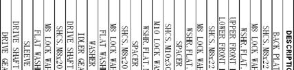
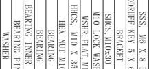
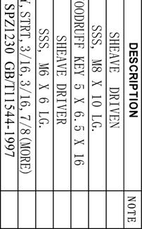
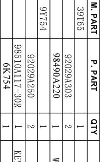
17 FIG.10 AGF Parts OE568 39F33 BEARING (1 EACH) 5M622 6F M3 2U683 2E135 PIG.9 FIG.9 AGF Parts SHAFT 1B 380 1B 367 LIFTER BUTTON 7E158 CASTING 3IQ13 1T385 1U389 RACE 96717A H AG K73 3D799 2Y
18
19


20
21
22 Due to continuous improvements, FORMTEK reserves the right to modify the product design and specifications contained herein without notice. Please contact your Lockformer sales representative for the most current specification information. Use, publication, or sale of any images or content without the expressed written consent of FORMTEK is strictly prohibited. Visit Our Web Site at: or VER. INT. LK24-00-CE
LK-20 OPERATOR S MANUAL WITH AUTO-GUIDE POWER FLANGING ATTACHMENT INSTRUCTIONS AND PARTS DIAGRAM PITTSBURGH LOCK MODEL 20 A PRODUCT OF
 LK-20 OPERATOR S MANUAL PITTSBURGH LOCK MODEL 20 WITH AUTO-GUIDE POWER FLANGING ATTACHMENT INSTRUCTIONS AND PARTS DIAGRAM A PRODUCT OF VER. US. LK20-02 11-2005 WARNING THIS EQUIPMENT IS DESIGNED TO BE
INSTRUCTIONS & PARTS DIAGRAM Pittsburgh 20 or 22 Gauge with Auto-Guide Mounted. LKF Pittsburgh Gauge
 LKF Pittsburgh 0- Gauge INSTRUCTIONS & PARTS DIAGRAM Pittsburgh 0 or Gauge with Auto-Guide Mounted LKF Pittsburgh 0- Gauge Pittsburgh 0 or Gauge Instructions and Parts Diagram with Auto-Guide Flanger Mounted
20 Gauge Super-Speed. shoprpmachine
 Operator tor s s manual 20 Gauge Super-Speed 1 WARRANTY Our guarantee on the products we manufacture is limited to repair or replacement without charge, of any part found to be defective in materials or
Visit Our Our Our Web Site at:
 Visit Our Our Our Web Site at: ww w ww w w w w. l o c k f o rr r m e r r r. c o m 711 OGDEN AVENUE, LISLE, ILLINOIS 60532-1399 Phone (630) 964-8000 Fax (630) 964-5685 09-1998 Operator tor s manual 20 Gauge
TDC-Notcher OPERATOR S MANUAL INSTRUCTIONS AND PARTS DIAGRAM. TDC Hydraulic Notcher. VER. TDC-Notcher -CE PAGE 1
 TDC-Notcher TDC Hydraulic Notcher OPERATOR S MANUAL INSTRUCTIONS AND PARTS DIAGRAM VER. TDC-Notcher -CE 03-2006 PAGE 1 WARNING THIS EQUIPMENT IS DESIGNED TO BE OPERATED WITH ALL COVERS SECURED IN PLACE.
F-TDF OPERATOR S MANUAL PRODUCTION PRODUCTS, INC.
 F-TDF OPERATOR S MANUAL PRODUCTION PRODUCTS, INC. CONTENTS 1. SAFETY GUIDELINES... 1 1.1 Safety First... 1 1.2 Safety Precautions Before Starting the Machine... 1 1.3 Safety Precautions While Operating
Operator s Manual TDC-V A PRODUCT OF
 Operator s Manual TDC-V A PRODUCT OF VER. INT. TDC V-02 03-2005 TABLE OF CONTENTS Saftey Guidelines 2 Warranty 3 Saftey Sign-Off Sheet 4-5 Tooling 6 Installation 6 Operation of TDC Joint Profile Rollset
TIN KNOCKER FOURPLEX CLEAT FORMER INSTRUCTIONS & PARTS DIAGRAM
 TIN KNOCKER FOURPLEX CLEAT FORMER INSTRUCTIONS & PARTS DIAGRAM Sheet Metal Equipment Sales Inc. Dean P. O'Connell, President Green Bay, Wisconsin Phone - (90)-66-9966 Fax - (90)-66-9969 Website: www.sheetmetalequip.com
TK 20 GA. BUTTON LOCK ROLLFORMER
 1 TIN KNOCKER TK 20 GA. BUTTON LOCK ROLLFORMER INSTRUCTIONS & PARTS DIAGRAM TAAG MACHINERY CO. (Master Distributor) 1257-B Activity Dr. Vista, CA 92081 Tel: (800) 640-0746 Fax: (760) 727-9948 Website:
Lockformer / 20 Gauge Capacity Punch Snap Lock Machine
 Lockformer / 20 Gauge Capacity Punch Snap Lock Machine CAPACITY 20 Gauge Galvanized and Lighter MATERIAL REOUIREMENTS: (1) 1-5/16" Receiver Lock (2) 7/16 Button Flange (90º) Total amount of material 1-3/4".
Instruction Manual for HSPA Take-Up Units
 Installation Instruction Manual for HSPA Take-Up Units Warning: To ensure the drive is not unexpectedly started, turn off and lockout the power source before proceeding. Failure to observe these precautions
Safety, Operation, & Maintenance Manual Douglas CBM Cross Belt Magnetic Separator
 Safety, Operation, & Maintenance Manual Douglas CBM Cross Belt Magnetic Separator Warning: This manual must be read, understood, and followed by anyone that installs, operates, and maintains this product.
OWNER S MANUAL PRODUCT CODE: 2006T
 Jul-18 Product Code: 2006T OWNER S MANUAL PRODUCT CODE: 2006T HYDRAULIC PIPE BENDER 12,000KG Model Capacity Bending Die No of Attachments 12,000kg 1/2", 3/4", 1", 1-1/4", 1-1/2", 2" 6 Made in China to
EZ-EX Tape Head (2" & 3" )
") EZ-EX Tape Head (2" & 3" ) EZ-EX Tape Cartridge for Eastey Industrial Case Tapers User Guide EZ-EX Tape Head (2" & 3" ) EZ-EX Tape Cartridge for Eastey Industrial Case Tapers User Guide Revised 12/09/2016
EZ-EX Tape Head (2" & 3" ) EZ-EX Tape Cartridge for Eastey Industrial Case Tapers User Guide EZ-EX Tape Head (2" & 3" ) EZ-EX Tape Cartridge for Eastey Industrial Case Tapers User Guide Revised 12/09/2016
KWSL2000RM ! CAUTION!! READ AND UNDERSTAND THIS MANUAL BEFORE INSTALLATION AND OPERATION OF THIS PRODUCT. DO NOT RETURN THIS PRODUCT TO SELLER.
 Assembly & Operating Instructions KWSL2000RM 2000 Lb. 12VDC Electric Winch! CAUTION!! READ AND UNDERSTAND THIS MANUAL BEFORE INSTALLATION AND OPERATION OF THIS PRODUCT. DO NOT RETURN THIS PRODUCT TO SELLER.
Flip - Up Conveyor. for 10" BeltVeyors OWNER'S MANUAL (12/00)
") Flip - Up Conveyor for 10" BeltVeyors OWNER'S MANUAL 19023100 (12/00) Table of Contents Warranty Information............................ Inside Front Cover Operator Qualifications........................................
Flip - Up Conveyor for 10" BeltVeyors OWNER'S MANUAL 19023100 (12/00) Table of Contents Warranty Information............................ Inside Front Cover Operator Qualifications........................................
TABLE OF CONTENTS CHAPTER 1.. CHAPTER 2.. CHAPTER 3.. CHAPTER 4.. CHAPTER 5.. CHAPTER 6.. CHAPTER 7.. CHAPTER 8.. CHAPTER 9..
 CHAPTER 1.. CHAPTER 2.. CHAPTER 3.. CHAPTER 4.. CHAPTER 5.. CHAPTER 6.. CHAPTER 7.. CHAPTER 8.. CHAPTER 9.. CHAPTER 10... CHAPTER 11... CHAPTER 12... TABLE OF CONTENTS SPECIFICATIONS:...1 PRECAUTIONS:...2
ATTENTION. 1. Do not attempt to use the power unit to extend your cylinder. This must be done manually.
 NSS8XLT Installation Manual ATTENTION By following the instructions in this manual you can save yourself much time, frustration and money. The installation of your lift will take 4-5 hours. Do not rush.
Outload Trough Roller Conveyor
 Outload Trough Roller Conveyor OWNER'S MANUAL 00003400 (8/99) Table of Contents Warranty Information.............................. Inside Front Cover Operator Qualifications / Sign Off Sheet..............................
ELECTRIC HYDRAULIC GEAR PUMP
 ELECTRIC HYDRAULIC GEAR PUMP 46169 ASSEMBLY AND OPERATING INSTRUCTIONS 3491 Mission Oaks Blvd., Camarillo, CA 93011 Visit our Web site at http://www.harborfreight.com Copyright 2001 by Harbor Freight Tools.
Owner s Manual. Mortar / Plaster Mixer. Models M785 M1000 M1200
 Owner s Manual Mortar / Plaster Mixer Models M785 M1000 M1200 Tiger Equipment LLC. 15 Byrd Lane Rocky Mount, VA 24151 Tel: 540-489-7777 Fax: 540-489-7778 www.tigerequip.com 1. PREFACE This manual contains
AutoStream - Model HV. Manual
 AutoStream - Model HV Manual Part Number: 901546 This Product Guide supports autoloader part number 311-0314 with serial numbers beginning with B1011Axxx 2014 Thiele Technologies, Inc. - Streamfeeder.
Flexfence Tension Unit. with Hand Pump. Product Manual. Release 02/16.
 Flexfence Tension Unit with Hand Pump Product Manual www.ingalcivil.com.au 1.0 Safety Precautions 1.1 Personal Protection While operating this equipment it is recommended that the following personal protective
1 2 3a 3b THREADING CARD 9 10 ABC Office
 1 2 3a 3b 4 5 6 7 8 9 10 THREADING CARD Important Safety instructions YOUR SAFETY AS WELL AS THE SAFETY OF OTHERS IS IMPORTANT TO GBC. IN THIS INSTRUCTION MANUAL AND ON THE PRODUCT ARE IMPORTANT SAFETY
ACI Hoist & Crane. Festoon System. 689 S.W. 7th Terrace Dania, FL (954) Fax (954) Toll Free A-HOIST ( )
 Fax (954) Toll Free A-HOIST ( )") ACI Hoist & Crane Festoon System 689 S.W. 7th Terrace Dania, FL 33004 (954) 921-1171 Fax (954) 921-7117 Toll Free 1-888-4-A-HOIST (1-888-424-6478) www.acihoist.com 2 Standard Duty C-Track Index 1. General
ACI Hoist & Crane Festoon System 689 S.W. 7th Terrace Dania, FL 33004 (954) 921-1171 Fax (954) 921-7117 Toll Free 1-888-4-A-HOIST (1-888-424-6478) www.acihoist.com 2 Standard Duty C-Track Index 1. General
ELECTRIC SLIP ROLL MACHINE MODEL: ESR-1016X1.5 ESR-1300X1.5 ESR-2000X1.0
 ELECTRIC SLIP ROLL MACHINE MODEL: ESR-1016X1.5 ESR-1300X1.5 ESR-2000X1.0 Operation Manual Table of contents I Main Specification Page 2 II Machinery general safety warnings Page 2 III Instructions.Page
Instruction Manual. Single Acting Hydraulic Aluminium Pull Cylinders RAP Series. Maximum Operating Pressure 700 bar
 Single Acting Hydraulic Aluminium Pull Cylinders RAP Series Maximum Operating Pressure 700 bar ABSOLUTE EQUIPMENT PTY LTD 2/186 Granite Street, GEEBUNG QLD 4034 Australia sales@absoluteequipment.com.au
SAFETY RULES SPECIFICATIONS READ ALL INSTRUCTIONS BEFORE OPERATING SAVE THESE INSTRUCTIONS
 READ ALL INSTRUCTIONS BEFORE OPERATING SAVE THESE INSTRUCTIONS Thank you for purchasing 7" Polisher. Before attempting to operate your new Polisher please read these instructions thoroughly. You will need
Package Contents Part A (3) I-Beam (1) Base (2) Other parts
 I-Beam (1) Base (2) Other parts") Page 1 Installation Instructions for 81245 Adjustable Height Gantry Crane 1-Ton Capacity Table of Contents Important Safety Information pg. 2 Specific Operation Warnings pg. 2 Main Parts of Product pg.
Page 1 Installation Instructions for 81245 Adjustable Height Gantry Crane 1-Ton Capacity Table of Contents Important Safety Information pg. 2 Specific Operation Warnings pg. 2 Main Parts of Product pg.
WINDSHIELD REMOVAL KIT
 WINDSHIELD REMOVAL KIT 94180 ASSEMBLY AND OPERATING INSTRUCTIONS Due to continuing improvements, actual product may differ slightly from the product described herein. 3491 Mission Oaks Blvd., Camarillo,
Technical Support (707)
") Installation Instructions CONSOLE MEGASHIFTER Fits: 1982-1992 Camaro & Firebird w/automatic Transmission *except 1988-1992 Firebird Formula Model Catalog # 80692 WORK SAFELY! For maximum safety, perform
Installation Instructions CONSOLE MEGASHIFTER Fits: 1982-1992 Camaro & Firebird w/automatic Transmission *except 1988-1992 Firebird Formula Model Catalog # 80692 WORK SAFELY! For maximum safety, perform
Di-Acro 12 & 24 Slip Rollers
 OPERATOR S MANUAL & INSTRUCTIONS Di-Acro & Slip Rollers Di-Acro, Incorporated PO Box 9 Canton, Ohio Progress Street N.E. Canton, Ohio --9 -- (fax) Revised / Sale or distribution of manuals is strictly
Hydraulic Hand Pallet Trucks
 Operating Instructions & Parts Manual 12U124 Please read and save these instructions. Read carefully before attempting to assemble, install, operate, or maintain the product described. Protect yourself
On-A-Roll Lifter Instruction Manual for Standard Models Read Before Use!
 On-A-Roll Lifter Instruction Manual for Standard Models Read Before Use! Important instructional, safety and precautionary information! It is the user s responsibility to exercise good judgment, common
M661 Instruction Manual
 M661 Instruction Manual Please inspect your machine carefully upon receipt. Let us know immediately if you note any damage. -IMPORTANT NOTICE- THIS MACHINE IS NOT TO BE OPERATED BY ANYONE UNTIL HAVING
OPERATION AND MAINTENANCE MANUAL
 WREN IBT SERIES HYDRAULIC TORQUE WRENCHES IBT SQUARE DRIVE SERIES OPERATION AND MAINTENANCE MANUAL FOR WREN Products: POINT 75, 1IBT, 3IBT, 5IBT, 8IBT, 10IBT, 20IBT, 25IBT, 35IBT, 50IBT SQUARE DRIVE HYDRAULIC
CONTENTS: 5740AH - 40 Ton Air/Hydraulic Shop Press 5750AH - 50 Ton Air/Hydraulic Shop Press OWNER'S MANUAL
 OWNER'S MANUAL CONTENTS: Page 1 Specifications 2 Safety Information and Warranty Information 3 Parts List 4-6 Assembly Instructions 7 Pump and Ram Assembly Instructions 8 Procedure for Bleeding Air 9 Pump
Bearing Race Service Kit
 0907 Safety Warning Read all instructions and safety warnings prior to operation. Failure to do so could result in equipment damage, personal injury or even death. CAUTION: USE REPLACEMENT PARTS AND ACCESSORIES
The portable, hand-held rebar bending and cutting system. OPERATOR S MANUAL Made in U.S.A.
 The portable, hand-held rebar bending and cutting system. OPERATOR S MANUAL -800-665-7549 Made in U.S.A. Thank you for purchasing an EZE BEND SYSTEM. The OPERATOR S MANUAL provides information for all
PRODUCT MANUAL TILE CUTTING MACHINE. . Operation. Parts List and Diagram SPECIFICATIONS CAUTION:
 FLORCRAFTT TM PRODUCT MANUAL SKU NUMBER 709-4242 SERIAL NUMBER: CAUTION: FOR YOUR OWN SAFETY READ INSTRUCTION MANUAL COMPLETELY AND CAREFULLY BEFORE OPERATING THIS 7 TILECUTTING MACHINE SPECIFICATIONS
Operating and Assembly Manual
 Model 1080 Operating and Assembly Manual Midwest Equipment Manufacturing, Inc. 5225 Serum Plant Road Thorntown, IN 46071 08-02-16 SAFETY RULES Remember, any power equipment can cause injury if operated
DEMOUNTABLE BODY INSPECTION PROCEDURE Follow Detailed Instructions Inside for Each Step
 DEMOUNTABLE BODY INSPECTION PROCEDURE Follow Detailed Instructions Inside for Each Step Inspection Date: Inspected By: Serial #: Unit #: INSPECT: Inspected OK Needs Repair Comments Front Locking Bar Rear
Installation Instructions Pro Bandit Shifter Fits: GM Powerglide Automatic Transmissions
 Installation Instructions Pro Bandit Shifter Fits: 1962-1973 GM Powerglide Automatic Transmissions Part # 80793 WORK SAFELY! For maximum safety, perform this installation on a clean, level surface and
WHEEL KIT FOR 13 HP GENERATOR
 WHEEL KIT FOR 13 HP GENERATOR 94192 ASSEMBLY AND OPERATING INSTRUCTIONS Due to continuing improvements, actual product may differ slightly from the product described herein. 3491 Mission Oaks Blvd., Camarillo,
Model 858-RH. Operating and Assembly Manual. Palmor Products Inc Serum Plant Road Thorntown, IN 46071
 Model 5-RH Operating and Assembly Manual Palmor Products Inc. 55 Serum Plant Road Thorntown, IN 6071 3/31/015 SAFETY RULES Remember, any power equipment can cause injury if operated improperly or if the
750 Series Press Conveyor Installation and Maintenance Manual
 750 Series Press Conveyor Installation and Maintenance Manual Metzgar Conveyor Co. - 2010 METZGAR CONVEYORS SAFETY PRECAUTIONS WARNING: DO NOT ATTEMPT MAINTENANCE ON ANY CONVEYORS WHILE IN OPERATION. BEFORE
Safety, Operation & Maintenance Manual
 Safety, Operation & Maintenance Manual Douglas Titan IBA Adjustable Impact Bed Warning: This manual must be read, understood, and followed by anyone that installs, operates, and maintains this product.
Operating and Assembly Manual
 Model 470-/H/PRO/IC Operating and Assembly Manual Midwest Equipment Manufacturing, Inc. 5225 Serum Plant Road Thorntown, IN 46071 11-11-11 SAFETY RULES Remember, any power equipment can cause injury if
Cyclone 600 Upcut Cut Off Saw
 Cyclone 600 Upcut Cut Off Saw WARNING The operator must thoroughly read and understand this manual before operating the cut off saw or starting any servicing. All safety and warning instructions should
WINCHMAX. Hydraulic Winch Instructions b b b
 WINCHMAX Hydraulic Winch Instructions 1010001b 1510001b 2010001b Safety warnings and precautions WARNING: When using the tool, basic safety precautions should always be followed to reduce the risk of personal
Bucket Grease Pump ASSEMBLY AND OPERATING INSTRUCTIONS
 Bucket Grease Pump 9793 ASSEMBLY AND OPERATING INSTRUCTIONS 349 Mission Oaks Blvd., Camarillo, CA 930 Visit our Web site at http://www.harborfreight.com Copyright 2004 by Harbor Freight Tools. All rights
OPERATION AND PARTS MANUAL
 OPERATION AND PARTS MANUAL MODEL NUMBER : PART NUMBER : GTL 1110 1900-0510 SERIAL NUMBER : BAYNE MACHINE WORKS, INC. PHONE: (864) 288-3877 910 FORK SHOALS ROAD TOLL FREE: (800) 535-2671 GREENVILLE S.C.,
Maintenance and Repair
 Maintenance and Repair WARNING ALWAYS shut off the engine, remove key from ignition, make sure the engine is cool, and disconnect the spark plug and positive battery terminal from the battery before cleaning,
Installation and Operation Manual Flo-Sense NH 3 Flow Indicator System
 Installation and Operation Manual Flo-Sense NH 3 Flow Indicator System September 2013 Form FVC098 - Rev 02 IMPORTANT: KEEP THIS DOCUMENT WITH THE PRODUCT UNTIL IT REACHES THE END USER. 1. Contact with
STEEL SIDE PANEL KIT. Model (FOR USE WITH MODEL FOLDABLE UTILITY TRAILER)
") STEEL SIDE PANEL KIT Model 47423 (FOR USE WITH MODEL 42709 FOLDABLE UTILITY TRAILER) Set up and Operating Instructions (MODEL 42709 TRAILER and TARP NOT INCLUDED. TARP SOLD SEPARATELY. Shown for illustration
STEEL SIDE PANEL KIT Model 47423 (FOR USE WITH MODEL 42709 FOLDABLE UTILITY TRAILER) Set up and Operating Instructions (MODEL 42709 TRAILER and TARP NOT INCLUDED. TARP SOLD SEPARATELY. Shown for illustration
DeZURIK " BAW AWWA BUTTERFLY VALVES WITH EPOXY-RETAINED SEAT
 DeZURIK 20 144" BAW AWWA BUTTERFLY VALVES WITH EPOXY-RETAINED SEAT Instruction D10373 April 2017 Instructions These instructions provide information about the 20 (250 F2 model only) and the 24-144 BAW
 Page 1 of 29 2003 Ford Thunderbird 3.9L Eng WATER LEAKS - REMOVABLE ROOF AND CONVERTIBLE TOP - SERVICE TIPS TECHNICAL SERVICE BULLETIN Reference Number(s): 04-9-5, Date of Issue: May 17, 2004 FORD: 2002-2005
2-1/4 Gallon Sprayer
 2-/4 Gallon Sprayer 94008 ASSEMBLY AND OPERATING INSTRUCTIONS 349 Mission Oaks Blvd., Camarillo, CA 930 Visit our Web site at http://www.harborfreight.com Copyright 2005 by Harbor Freight Tools. All rights
Maintenance Instructions
 General Note These instructions contain information common to more than one model of Bevel Gear Drive. To simplify reading, similar models have been grouped as follows: GROUP 1 Models 11, 0, 1,, (illustrated),,
THT-100 ASTG THT-100 ASTG2 Security Turnstiles. Installation, Operation and Maintenance Manual. 1 Rev
 THT-100 ASTG THT-100 ASTG2 Security Turnstiles Installation, Operation and Maintenance Manual 1 Rev 0103.01 CONTENTS IMPORTANT SAFEGUARDS........................................3 SAFETY PRECAUTIONS...........................................3
Model: SPTOGT01 TRACTOR PTO GENERATOR
 www.scintex.com.au sales@scintex.com.au Model: SPTOGT01 TRACTOR PTO GENERATOR SET UP, OPERATING, AND SERVICING INSTRUCTIONS Read this material before using this product. Failure to do so can result in
CONTENTS: Ton Hydraulic Shop Press w/ Winch Ton Hydraulic Shop Press w/ Winch OWNER'S MANUAL
 OWNER'S MANUAL CONTENTS: Page 1 Specifications 2 Safety Information and Warranty Information 3 Parts List 4-8 Assembly Instructions 9 Procedure for Bleeding Air 10 Pump Instructions 11-12 Winch Kit List
MODEL RF. Drain Cleaning Machine. Operator s Manual
 MODEL RF Drain Cleaning Machine Operator s Manual!!!! FOR YOUR SAFETY Before you operate or maintenance this equipment, READ this manual carefully and completely! The Electric Eel Model RF Drain Cleaning
AET48 Owner s Manual. TOW AERATOR Owner s Manual AET48 Beginning Serial #: Replacement Parts
 Tine Row Kit Complete tine row set for replacement of one complete row of tines. Includes mounting plates, spacer, and all hardware. TOW AERATOR Owner s Manual AET48 Beginning Serial #: 0206001 Tine Kit
50 Ft. Retractable Cord Reel
 50 Ft. Retractable Cord Reel with Triple Tap Owner s Manual WARNING: Read carefully and understand all ASSEMBLY AND OPERATION INSTRUCTIONS before operating. Failure to follow the safety rules and other
Heavy Duty U-Joint Service Kit
 Heavy Duty U-Joint Service Kit 00 Safety Warning Read all instructions and safety warnings prior to operation. Failure to do so could result in equipment damage, personal injury or even death. CAUTION
Compressor Duty Motor - 1 HP. Model 40132
 Compressor Duty Motor - 1 HP Model 40132 Assembly and Operating Instructions 3491 Mission Oaks Blvd., Camarillo, CA 93011 Visit our web site at http://www.harborfreight.com Copyright 2002 by Harbor Freight
GRSM17 Pneumatic Center Punch Tool Owner s Manual and Operating Instructions
 Owner s Manual and Operating Instructions Table of Contents Page Information 2 Safety Guidelines and Warranty 3 Overview and Installation 4 Air System Requirements 5 Setting Controls 6 Installing Clamps
Operating and Maintenance Instructions
 HIGH SPEED ALLOY GRINDER MODEL AG05 Operating and Maintenance Instructions Sales, Service, and Technical Assistance Call Toll Free 800 / 654-4519 Ray Foster Dental Equipment 5421 Commercial Dr, Huntington
OPERATION AND PARTS MANUAL
 OPERATION AND PARTS MANUAL MODEL NUMBER : PART NUMBER : GRL 1110 1900-0540 SERIAL NUMBER : BAYNE MACHINE WORKS, INC. PHONE: 864.288.3877 910 FORK SHOALS ROAD TOLL FREE: 800.535.2671 GREENVILLE SC, 29605
JOHN DEERE WORLDWIDE COMMERCIAL & CONSUMER EQUIPMENT DIVISION. Lawn Tractors L100, L110, L120, and L130 TM2026 DECEMBER 2002 TECHNICAL MANUAL
 2026 December 2002 JOHN DEERE WORLDWIDE COMMERCIAL & CONSUMER EQUIPMENT DIVISION Lawn Tractors L100, L110, L120, and L130 TM2026 DECEMBER 2002 TECHNICAL MANUAL North American Version Litho in U.S.A. SAFETY
MINIATURE ALUMINUM JACK STANDS (1 PAIR) Model 90892
 Model 90892") MINIATURE ALUMINUM JACK STANDS (1 PAIR) Model 90892 ASSEMBLY and OPERATING INSTRUCTIONS 3491 Mission Oaks Blvd., Camarillo, CA 93011 Visit our Web site at http://www.harborfreight.com Copyright 2003 by
MINIATURE ALUMINUM JACK STANDS (1 PAIR) Model 90892 ASSEMBLY and OPERATING INSTRUCTIONS 3491 Mission Oaks Blvd., Camarillo, CA 93011 Visit our Web site at http://www.harborfreight.com Copyright 2003 by
Instruction Manual. Single Acting, Pancake, Locking Collar Hydraulic Cylinders RPLC Series. Maximum Operating Pressure 700 bar
 Single Acting, Pancake, Locking Collar Hydraulic Cylinders RPLC Series Maximum Operating Pressure 700 bar ABSOLUTE EQUIPMENT PTY LTD 2/186 Granite Street, GEEBUNG QLD 4034 Australia sales@absoluteequipment.com.au
Sawhorse with Chainsaw Holder
 Sawhorse with Chainsaw Holder Owner s Manual Chainsaw not included. WARNING: Read carefully and understand all ASSEMBLY AND OPERATION INSTRUCTIONS before operating. Failure to follow the safety rules and
50 Gallon Skid Sprayer
 50 Gallon Skid Sprayer Model #: KS50P5 User Manual Read this manual for complete instructions Model #: KS50P5 Table of Contents Warranty... 3 General Safety Information... 3 Hazardous Substance Alert...
2 TON CAPACITY PROFESSIONAL SERIES ALUMINUM JACK OWNER'S MANUAL SPECIFICATIONS
 80006 OWNER'S MANUAL CONTENTS: Page 1 Specifications 2 Warning Information 3 Setup, Operating and Preventative Maintenance 4 Troubleshooting 5 Maintenance 6 Exploded View Drawing and Replacement Parts
HYDRAULIC SPRING COMPRESSOR SET
 HYDRAULIC SPRING COMPRESSOR SET Model 47890 ASSEMBLY and OPERATING INSTRUCTIONS 3491 Mission Oaks Blvd., Camarillo, CA 93011 Visit our Web site at http://www.harborfreight.com Copyright 2002 by Harbor
BUCKET SWEEPER OPERATORS & PARTS MANUAL 2852 & 3174 SERIES
 OM628 BUCKET SWEEPER OPERATORS & PARTS MANUAL 2852 & 3174 SERIES MODEL 12002-5 FOOT WIDE X 24 INCH DIAMETER (SKID-STEER) MODEL 12004-6 FOOT WIDE X 24 INCH DIAMETER (SKID-STEER) MODEL 12017-6 FOOT WIDE
The Chameleon Trac II Patent Pending M-Series User s Manual
 The Chameleon Trac II Patent Pending M-Series User s Manual YOU MAY ALSO VIEW OUR GENERAL OPERATION VIDEO ONLINE AT: www.marionbrush.com Please read entire manual prior to using this system. Page 1 The
PRO RATCHET UNIVERSAL SHIFTER
 Installation Instructions PRO RATCHET UNIVERSAL SHIFTER Fits: GM, Ford and Chryslers w/automatic Transmission See Application Guide for Specific Vehicles Catalog # 80842 WORK SAFELY! For maximum safety,
Mulcher Operators Manual
 Mulcher Operators Manual Skid Pro Attachments PO Box 982 Alexandria, MN 56308 October 2015 1 2 Contents 1. Introduction And Warranty... 4 1.1 Introduction... 4 1.2 Warranty... 4 2. Component Identification...
Operating and Maintenance Instructions
 HIGH SPEED ALLOY GRINDER MODEL AG03 Foster Operating and Maintenance Instructions Sales, Service, and Technical Assistance Call Toll Free 800 / 654-4519 Ray Foster Dental Equipment 5421 Commercial Drive
 Operation and Maintenance Manual Model.75,, 3, 5, 8, 0, 0, 5, 35, 50 http://www.torsionx.com Use the MaxDrv Series Square Drive Torque Wrench Model.75,, 3, 5, 8, 0, 0, 5, 35, 50 to install and remove threaded
Kwikee Platinum Series OWNER'S MANUAL
 Kwikee Platinum Series OWNER'S MANUAL TABLE OF CONTENTS Safety Information 2 Product Information 2 General Service Notes 3 Prior To Operation 3 Operation 4 Step with Control Unit 4 Troubleshooting 5 Step
OPERATIONS MANUAL LEVER CHAIN HOIST
 OPERATIONS MANUAL LEVER CHAIN HOIST IMPORTANT SAFETY INFORMATION Please read, understand and follow all safety information contained in these instructions prior to the use of this hoist. Retain these instructions
 DRUM BRAKE RIMS Periodic inspection of drum brake rims is necessary to determine indications of uneven or excessive wear. In general, brake rim failures other that regular wear are caused by brake linings
IMPORTANT SAFETY NOTICE
 IMPORTANT SAFETY NOTICE To: Our Valued Customers User safety is a major focus in the design of our products. Following the precautions outlined in this manual will minimize your risk of injury. ITT Goulds
Owner s Manual: PS4000 4,000 LB. WINCH
 Owner s Manual: PS4000 4,000 LB. WINCH PIERCE ARROW INC. 549 U.S. HWY 287 S. HENRIETTA, TEXAS 76365 ---------------------------------------------------- TOLL FREE 800-658-6301 FAX 940-538-4382 ----------------------------------------------------
Quick Install Lift AL065 Installation Guide & Owners Manual
 Quick Install Lift AL065 Installation Guide & Owners Manual Congratulations on your new lift purchase. The Quick Install Lift line is one of the easiest and most trouble free ways to transport your scooter
SERIES OPERATION AND MAINTENANCE MANUAL
 SERIES OPERATION AND MAINTENANCE MANUAL This manual CONTAINS IMPORTANT WARNINGS, S and OTHER INSTRUCTIONS. Read and understand the instruction manual Carefully, before use and retain it for reference.
I-317. AWWA Check Valves WARNING INSTALLATION AND MAINTENANCE INSTRUCTIONS SERIES 317 WARNING
 Read and understand all instructions before attempting to install, remove, adjust, or perform maintenance on any Victaulic piping products Wear safety glasses, hardhat, and foot protection. Failure to
 Operation and Maintenance Manual http://www.torsionx.eu Use the MaxDrv Series Square Drive Torque Wrench Model.75, 1, 3, 5, 8, 10, 20, 25, 35, 50 to install and remove threaded fasteners requiring precise
Walk-Behind Sprayer SL-80 & SL-80SS. Owner's Manual and Installation Instructions Original Instructions CAUTION
 April 15, 2017 Lit. No. 74419, Rev. 00 Walk-Behind Sprayer SL-80 & SL-80SS Owner's Manual and Installation Instructions Original Instructions CAUTION Read this document before operating or servicing the
Fig.01 Fig.02 Fig.03. Disassembly & Reassembly Instructions SBV-HP - Page 3
 M12A14 WITH FLOATING BACKSEAT 3 Fig.01 Fig.02 Fig.03 Disassembly & Reassembly Instructions SBV-HP - Page 3 M12A14 WITH FLOATING BACKSEAT 3 1. Caution, before any attempt is made to disassemble, verify
Service Access Cover. Vacuator Valve. Accessories
 Under Hood Mount, Two-Stage Filtration For Large Construction & Mining Equipment The FTG Cycloflow Air Cleaner is another two-stage air cleaner with a built-in pre-cleaner. This air cleaner has axial seal
Installation Instructions. QuickSilver Shifter. Fits: GM, Ford, Chrysler Transmissions See Application Guide for Specific Applications Part # 80683
 Installation Instructions QuickSilver Shifter Fits: GM, Ford, Chrysler Transmissions See Application Guide for Specific Applications Part # 80683 WORK SAFELY! For maximum safety, perform this installation
BINKS MODEL 460 LIGHTWEIGHT AUTOMATIC SPRAY GUN
 SERVICE MANUAL EN BINKS MODEL 460 LIGHTWEIGHT AUTOMATIC SPRAY GUN AIR FLOW ADJUSTMENT Clockwise to reduce pressure; Counterclockwise to increase pressure. 1/2" DIA. MOUNTING HOLE FLUID NEEDLE ADJUSTMENT
Airless Spray Gun INSTRUCTIONS DP psi (345 bar) Maximum Working Pressure
 Maximum Working Pressure") INSTRUCTIONS DP-6376 Airless Spray Gun 5000 psi (345 bar) Maximum Working Pressure INSTRUCTIONS This manual contains important warnings and information. READ AND KEEP FOR REFERENCE. Table of Contents Warnings......................................
INSTRUCTIONS DP-6376 Airless Spray Gun 5000 psi (345 bar) Maximum Working Pressure INSTRUCTIONS This manual contains important warnings and information. READ AND KEEP FOR REFERENCE. Table of Contents Warnings......................................
Photo 1. Shift pattern gate plate
 Installation Instructions MAGNUM GRIP STREET BANDIT SHIFTER Fits: GM, Chrysler, and Ford Automatic Transmissions See Application Guide for Specific Vehicles Catalog # 81050 WORK SAFELY! For maximum safety,
OPERATIONAL INSTRUCTION OVERVIEW MAINTENANCE CHECKLIST
 OPERATIONAL INSTRUCTION OVERVIEW Operation Both manual and electrically powered winches develop tremendous forces; therefore, all backstops must be operated by qualified personnel only to avoid structural