TIN KNOCKER FOURPLEX CLEAT FORMER INSTRUCTIONS & PARTS DIAGRAM
|
|
|
- Rosalind Pope
- 5 years ago
- Views:
Transcription
-66-9966 Fax - (90)-66-9969 Website: www.sheetmetalequip.")
1 TIN KNOCKER FOURPLEX CLEAT FORMER INSTRUCTIONS & PARTS DIAGRAM Sheet Metal Equipment Sales Inc. Dean P. O'Connell, President Green Bay, Wisconsin Phone - (90) Fax - (90) Website: 0/4/03

2 TIN KNOCKER SAFETY RULES FOURPLEXCLEAT FORMER. WARNING: Electrical Danger---Misuse or improper installation of machinery connected to a source of electricity may result in accidental shock that could cause injury or death. Installation must conform to National Electric Code (Article 50Grounding, etc.) A trained and qualified electrician must make electrical connections. Electrical characteristics shown on motor plate and control panel must match the power source; and all electrically powered equipment must be grounded.
. Failure to comply will lead to personal body injury. 3.")
3 3. WARNING: Mechanical Danger- the power driven forming rolls rotate at all times when power is supplied to the motor. Never place any part of the body including loose clothing near or onto the rotating rolls. (KEEP HANDS AWAY). Failure to comply will lead to personal body injury. 3. Never clean forming rolls while rolls are rotating turn power off to clean rolls. 4. Machine to be operated by authorized personnel who have been trained by their supervisor with the working and safety features of the machine, and by reading and understanding the Operator s Manual. 5. Do not operate FOURPLEX CLEAT FORMER without reading operator s Manual and without proper supervisory instructions. 6. Perform all installation and set-up operations before applying power for electrical start-up.
4 4 7. Never operate machine with any guard removed; i.e., all required guarding to be installed and effective. Do not override the safety features of the equipment. Do not remove, paint over, alter, or deface any machine-mounted warning and instruction plates and signs. 8. Never leave machine running unattended. When not in use, turn off electrical power. 9. Never adjust machine with power on. 0. Avoid accidental start-up.. Do not use machine if servicing is required.. Safety glasses and protective tools are recommended. WARRANTY All new SME machines are sold with a one-year limited warranty, on factory defective parts. The warranty is limited to the original user. SME at its option, will repair, replace or refund the purchase price of any part, tool or machine that fails during the warranty period. SME will pay normal shipping charges for replacement parts. After 90 days from date of purchase, all express or overnight delivery charges are the responsibility of the customer. Purchaser must contact SME, at the address below, any written claim, with proof of original purchase. Replacement parts will be invoiced to purchaser and credit issued when the failed part is delivered to SME. Removal, reinstallation or replacement parts shall be at purchasers / user s expense. Failure due to improper use of the machine voids the warranty. NOTE:. This machine has been tested and adjusted prior to shipment, but can and often does require readjustment due to vibration and bouncing during transport. Following the procedures described within can easily do readjustment. These are procedures with which you, as a user, should be familiar, as you will use them repeatedly over the life use of the machine. If you have difficulty in performing these procedures, we are here to support you.. Opening rolls (for Philipsburg Lock)are consumable items and not subject to warranty. Sheet Metal Equipment Sales Inc. Dean P. O'Connell, President Green Bay, Wisconsin Phone - (90) Fax - (90) Website:
5 5 FOURPLEX CLEAT FORMER Instructions ELECTRICALS: 5 HP 30/460 volts three phase motor and controls, standard machine wired for 30 volt unless otherwise indicated. MACHINE SPECIFICATIONS: S CLEAT Capacity: gauge galvanize or lighter Stock Width: 3-5/ /3 DRIVE CLEAT Capacity: 0 gauge galvanize or lighter Stock Width: -/ /3 OPERATION: A. Strip Stock Start machine and place properly sheared material between properly aligned gauge bars and feed material into the rolls. Check end results and make changes accordingly. B. Sheet Feed with Slitter (Optional) Start machine and place sheet against proper gauge bar and feed material into the slitting rolls being sure to keep sheet against gauge bar. Do not force or try to influence the sheet in any way. Machine will automatically feed cut sheet into forming rolls and deflect balance of sheet over machine cover. On long sheets, best results will be had by turning sheet so that the trail end on the first cut becomes the lead end on the second cut, etc. This procedure will eliminate any tendency for Trailing-Off on the slit part.
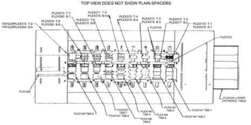
6 6 FOURPLEX CLEAT FORMER Instructions ADJUSTMENTS: The top plate and roll assembly is split into 3 zones of 3 rolls each with simple six point adjustment for each zone. Begin adjustment by tightening all hold down nuts to their solid position then loosen as follows: A. Zone all studs ½ turn loose B. Zone all studs ¾ turn loose C. Zone 3 all studs turn loose Should machine labor under load stud settings should be loosened /8 to ¼ turn. Upward bow can be adjusted by lowering the exit adjusting screw located on the exit adjustment gauge assembly. Downward bow can be compensated by adjusting the hold down studs located at the exit end of the machine. Side bow is caused by an unbalanced stud adjustment. LUBRICATION: Lubrication fittings for the high-speed shafts are located under the stand auxiliary side panel. The high-speed bearings should be lubricated after every eight hours of operation (recommended lubricant-standard Oil Viscous #3, or equivalent.) Roll station #4 and #5 (part 44 and 45) on S Cleat are supplied with polished angle surface to eliminate friction and allow the material to flow smoothly during the forming sequence. The rolls should be lubricated periodically with an application of #0 or #30 SAE lubricating oil to insure a smooth sliding surface. NOTE: If machine is to be used or stored out-of-doors, an oil or grease film will prevent rusting of surfaces. INSTRUCTIONS FOR AUXILIARY ROLLS: Machine auxiliary shafts are designed to accommodate various auxiliary roll sets listed below. To install these rolls, proceed as follows:. Remove machine cover.. Remove tabletop side plate on side of machine rolls are to be mounted. 3. If auxiliary rolls are now on machine, remove retaining bolts and washers. Remove all parts not pertaining to the set to be used. 4. Place keys on shafts.
7 5. Select the first pair of rolls, which are marked T- and B- and place them on the shafts at the entrance of the machine (Feed Side). Place the T- roll on the upper shafts and B- on the lower. Repeat procedure with roll stations #,#3, and #4, etc. until all rolls have been mounted. All rolls marked T should be mounted on the top shafts and B rolls on the bottom shafts in numerical order. NUMBER SIDE OF ROLLS MUST FACE OUTWARD. 6. After rolls are installed, fasten rolls with retaining cap screws and washers. 7. Mount entrance and exit gauge bars to stand, using slotted holes provided in stand table top and set entrance gauge by placing a straight edge along the outer edge of the auxiliary rolls; measure the required amounts in from this straight edge to the extreme ends of the entrance gauge bar. See schedule below for various auxiliary sets. 7 A. 5/6 Auxiliary Pittsburgh(0 gauge and lighter) uses approximately material. Gauge Setting.//9 to -3/4 A slight taper in gauge setting may be required. NOTE: To install auxiliary opening roll holder, remove rolls from the #6 roll station and bolts that straddle the bottom 6 roll shafts (See Sketches #4 and #5). Place opening roll holder and slide on machine and fasten with the two ½- 3 x Hex Head Cap Screws Provided.
8 8 B. Drive Cleat Auxiliary (0 gauge and lighter) uses -/8 material. Gauge Setting -/8 C. Combination 3-in- rolls (capacity gauge and lighter), also -in-, uses approx. -3/4 On T section, -/8 on standing seam and ½ on right angle flange. Gauge Setting- 3-in- Gauge Bar: Top Step T Section -/6 Middle Step Standing Seam -/ Bottom Step Right Angle Flange... 5/6 Gauge Settings-Combination -in- Top Step T Section.-/6 BottomStep-Standing Seam.. -/ NOTE: When the first setting is made, the other two will automatically be correct. Placing material to the proper gauge step can make the other two shapes. The exit angle iron gauge has an adjustable bar that can be lowered to exert pressure on the material as it emerges from the rolls; thereby, straightening the finished section. See Sketch #3. NOTE: WHEN ADJUSTING THE EXIT GAUGE FROM THE 3-IN- COMBINATION, BE SURE TO SET IT TO THE T SECTION OR DAMAGE WILL RESULT BY MATERIAL INTERFERENCE WITH THE GAUGE BAR. D. Female Button Punch Snap lock (0 to 6 gauge galvanize) uses approx. -5/6 of material. Gauge Setting: -5/6 closest to forming rolls, -/3 furthest from forming rolls. Taper may be increased or decreased as required for most satisfactory results. Upward bow can be adjusted by rising or lowering the straightener roll located between stations 8 & 9. NOTE: To install slide between stations and 3, remove existing idler gear bolt and replace with longer bolt furnished with roll set. E. Male Button Punch Snap lock (0 to 30 gauge galvanize) uses approx. 7/6 of material. Gauge Setting 5/6 NOTE: Remove existing bolts between Top 4 and 5 rolls and Top 5 and 6 rolls and replace with idler bracket and bolts provided with roll set. See Sketch #6 and #6A.

9 9 CAUTION: Bottom # roll is not fastened with retaining C washer. Severe damage will result to roll if instructions are not followed. See Sketch #7. 8. When changing rolls, loosen the exit gauge and move it to the extreme ends of the table slots away from where the material will pass. Run a test piece of material through the rolls and stop the machine as the lead edge of the material formed reaches the end of the exit table. Set the exit gauge to the formed material the gauge should be flush with, but not bearing against, the material unless side pressure is required for straightening. Adjustment of the pressure on the 3/8 studs that pass through the plates will affect the shape and the tendency of the material to hold the entrance gauge. It is important that, when changing rolls, all parts pertaining to each set be removed from the machine and all parts for the set to be mounted be included on assembly. 9. Replace top cover and stand side plate. 0. Place material against gauge bar and feed into machine. NOTE: Roll coding is such that on similar rolls, the numbers will designate more than one Station. EXAMPLE: Combination 3-in- rolls have three rolls stamped LTC--3-B These rolls are to be placed one on the bottom 7 shafts and the other two on B-8 and 9. PREVENTATIVE MAINTENANCE: To provide efficient, trouble free operation and to prolong the life of this tool, we suggest periodic cleaning of all rolls to remove any galvanize build-up. Galvanize build-up can be reduced to a minimum by applying a light bodied lubricant to the forming rolls every six to eight hours of operation. All bolts and nuts should be tightened every month or more often as required. Transmission belts should be checked for wear and proper tension periodically. Air intake vents on motor should be kept clean to insure proper ventilation.
10 0
11
12

13 3 Parts List for FOURPLEXCLEAT FORMER TKFOURPLEX4 TKFOURPLEX4 TKFOURPLEX43 TKFOURPLEX44 TKFOURPLEX45 TKFOURPLEX57 TKFOURPLEX46 TKFOURPLEX47 TKFOURPLEX48 TKFOURPLEX70 TKFOURPLEX070 T&B Forming Roll S Cleat T & B T&B Forming Roll S Cleat T & B T&B Forming Roll S Cleat T3 & B3 T&B Forming Roll S Cleat T4 & B4 T&B Forming Roll S Cleat T5 & B5 T&B Forming Roll S Cleat T7 & B7 T&B Forming Roll S Cleat T6 & B6 T&B Forming Roll S Cleat T8 & B9 T&B Forming Roll S Cleat T9 &B9 Top Forming Roll Drive Cleat T Top Forming Roll Drive Cleat T, T3 & T4 3 TKFOURPLEX07 Top Forming Roll Drive Cleat T5
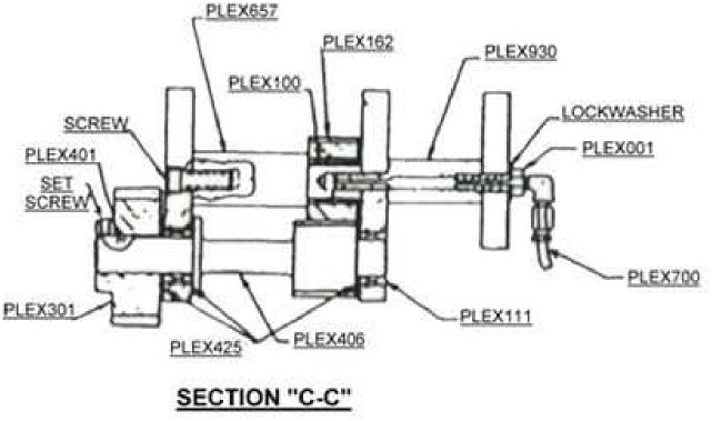
14 4 TKFOURPLEX07 TKFOURPLEX073 TKFOURPLEX074 TKFOURPLEX075 Top Forming Roll Drive Cleat T6 Top Forming Roll Drive Cleat T7 Top Forming Roll Drive Cleat T8 Top Forming Roll Drive Cleat T9 TKFOURPLEX076 TKFOURPLEX077 TKFOURPLEX078 TKFOURPLEX079 TKFOURPLEX080 Bottom Forming Roll Drive Cleat B Bottom Forming Roll Drive Cleat B Bottom Forming Roll Drive Cleat B3 Bottom Forming Roll Drive Cleat B4, B5 &B6 Bottom Forming Roll Drive Cleat B7, B8 & B9 3 3 TKFOURPLEX84 TKFOURPLEX30 TKFOURPLEX304 TKFOURPLEX406 TKFOURPLEX505 Roll Shafts st Drive Shafts nd Drive Shafts 3rd Drive Shafts Plain Spacer S Cleat -/4 x 5-/ TKFOURPLEX605 TKFOURPLEX657 TKFOURPLEX70 TKFOURPLEX703 TKFOURPLEX704 Idler Spacer Main Idler Spacer Plain Spacer Drive Cleat -/4 x -/3 Plain Spacer Drive Cleat -/ x 3/8 Roll Spacer Drive Cleat -3/8 x 7/3 /keyway TKFOURPLEX60 TKFOURPLEX6 TKFOURPLEX6 TKFOURPLEX30 TKFOURPLEX640 Driven Gear Idler Gear (needs Bearing) Main Idler Gear (needs Bearings) Driven Gear Main Collar 8 7 TKFOURPLEX66 TKFOURPLEX930 TKFOURPLEX8 TKFOURPLEX9 TKFOURPLEX0 TKFOURPLEX TKFOURPLEX303 TKFOURPLEX305 TKFOURPLEX55 TKFOURPLEX56 Thrust Collar Hex Spacer Lube Top Plate Bottom Front Plate Bottom Center Plate Bottom Back Plate Entrance Gauge Bar Drive Cleat Exit Bar Slide (Drive Cleat) Slide Holder TKFOURPLEX048 TKFOURPLEX464 TKFOURPLEX907 TKFOURPLEX908 TKFOURPLEX000 Bar Jack Motor Base Sheet Slide ( S Cleat Gear side) Sheet Slide Roll Grease Fit Shim TKFOURPLEX00 TKFOURPLEX5 TKFOURPLEX04 TKFOURPLEX900 TKFOURPLEX304 Lube Bolt Stand Cover Fiber Gear Assembly Exit Gauge ( S Cleat) TKFOURPLEX090 TKFOURPLEX00 TKFOURPLEX Bearing (B46 Torr) Bearing (B6 Torr) Bearing (HJ 64 Torr)
15 5 TKFOURPLEX30 TKFOURPLEX3 TKFOURPLEX4 TKFOURPLEX45 TKFOURPLEX700 Bearing (NTA 65 Torr) Bearing (TRC 65 Race) Bearing (TT503- Thrust) Bearing (TT709- Thrust) Plastic Tubes 4 pcs. 4 & 3 pcs TKFOURPLEX4 TKFOURPLEX44 TKFOURPLEX080 TKFOURPLEX98 Sheave BK3 x Sheave BK 45 x -/8 5 HP Phase 60 Cycle 800 RPM (84) Back Enclosure TKFOURPLEX80 TKFOURPLEX80 TKFOURPLEX803 TKFOURPLEX804 TKFOURPLEX805 TKFOURPLEX806 TKFOURPLEX807 TKFOURPLEX808 TKFOURPLEX809 TKFOURPLEX80 TKFOURPLEX8 TKFOURPLEX80 TKFOURPLEX8 TKFOURPLEX8 TKFOURPLEX83 TKFOURPLEX84 TKFOURPLEX85 TKFOURPLEX86 TKFOURPLEX87 TKFOURPLEX88 TKFOURPLEX89 TKFOURPLEX830 TKFOURPLEX83 TKFOURPLEX83 TKFOURPLEX833 TKFOURPLEX834 TKFOURPLEX835 TKFOURPLEX836 TKFOURPLEX840 TKFOURPLEX84 TKFOURPLEX84 TKFOURPLEX843 TKFOURPLEX844 TKFOURPLEX845 TKFOURPLEX846 TKFOURPLEX847 TKFOURPLEX848 TKFOURPLEX849 TKFOURPLEX850 TKFOURPLEX85 TKFOURPLEX85 TKFOURPLEX853 TKFOURPLEX854 TKFOURPLEX855 Button lock male T- Button lock male T- T-3 T-4 Button lock male T-6 Button lock male T-7 T-8 T-9 Button lock male B- Button lock male B- Button lock male B-3 Button lock male B-4 Button lock male B-5 Button lock male B-6 Button lock male B-7 B-8 B-9 Button lock female T- Button lock female T- Button lock female T-3 Button lock female T-4 Button lock female T-5 Button lock female T-6 Button lock female T-7 Button lock female T-8 Button lock female T-9 Button lock female B- Button lock female B- Button lock female B-3 Button lock female B-4 Button lock female B-5 Button lock female B-6 Button lock female B-7 Button lock female B-8 B-9 Pittsburgh T- Pittsburgh T- Pittsburgh T-3 Pittsburgh T-4 Pittsburgh T-5 Pittsburgh T-7 Pittsburgh T-8 Pittsburgh T-9 Pittsburgh B- Pittsburgh B- Pittsburgh B-3 Pittsburgh B-4 Pittsburgh B-5 Pittsburgh B-7 Pittsburgh B-8 Pittsburgh B
16 6 TKFOURPLEX860 TKFOURPLEX86 TKFOURPLEX86 TKFOURPLEX863 TKFOURPLEX864 TKFOURPLEX865 TKFOURPLEX866 TKFOURPLEX867 TKFOURPLEX868 TKFOURPLEX869 TKFOURPLEX870 TKFOURPLEX87 TKFOURPLEX87 TKFOURPLEX873 TKFOURPLEX874 TKFOURPLEX875 TKFOURPLEX876 TKFOURPLEX877 TKFOURPLEX003 TKFOURPLEX004 TKFOURPLEX005 TKFOURPLEX006 TKFOURPLEX007 TKFOURPLEX008 TKFOURPLEX009 TKFOURPLEX00 3- Rolls T- 3- Rolls T- 3- Rolls T-3 3- Rolls T-4 3- Rolls T-5 3- Rolls T-6 3- Rolls T-7 3- Rolls T-8 3- Rolls T-9 3- Rolls B- 3- Rolls B- 3- Rolls B-3 3- Rolls B-4 3- Rolls B-5 3- Rolls B-6 3- Rolls B-7 3- Rolls B-8 3- Rolls B-9 Belleville Washers Electrical Switch Plate studs Shim Washers.060 Shim Washers.065 Shim Washers.070 Shim Washers.075 Shim Washers


17 7 S AND DRIVE CLEAT CUTTER ATTACHMENTS Installation Instructions Maximum Capacity of Unit: Ga. Galv. (.0350 Material) Minimum Length of Cleat to be cut: 9 minimum. Set slitting attachment on entrance table so that so that the spur gear of the Attachment meshes with the gear of the No. forming roll. Refer to Sketch # or set-up.. By placing the template (furnished) across the slitter casting; thinnest side against casting and widest side against machine plate; leave an approximate /3 clearance between machine plate and template. Then bolt in place per Sketch #. A slight adjustment to the left or right may be required to provide the desired size of cut. NOTE: Template edge must be parallel to machine plate and slitter attachment casting. Alternate Set-Up Procedure: Place straight edge across the back of the slitter attachment casting and measure 7/3 from straight edge to machine plate. Take measurements at least apart to insure slitter attachment is parallel to machine plate. NOTE: Entrance gauge bar is factory set and should not need adjustment. Setting is given for reference only. 3. Replace machine cover.
18 8 S AND DRIVE CLEAT CUTTER ATTACHMENT Operation Instructions. Check settings and make sure all mounting bolts are tight.. Start machine and place the material against the entrance gauge bar of the slitting attachment and feed the stock into the slitting rolls. The slit material will automatically deflect downward to the forming roll while the piece in the operator s hand will deflect upward to clear the machine. The slitter will cut straight as long as the material, which has not gone thru the slitting rolls, is held against the entrance gauge bar. NOTE: WHEN RUNNING LONG SHEETS IT IS ADVISABLE THAT THE SHEET BE SUPPORTED AT APPROXIMATELY THE SAME HEIGHT AS THE SLITTING ATTACHEMENT ENTRANCE TABLE. ADJUSTMENT The slitter is properly adjusted and tested before shipment. Should the gauge accidentally become misaligned, refer to installation instructions paragraph. If the cleat runs out, or if material distribution is not correct, check the mounting of the attachment making sure the unit is mounted parallel to the machine side plates and settings are correct. When the slitting rolls need resharpening remove the bottom roll and grind it on the O.D. to remove any nicks and present a clear sharp edge. The top roll has two cutting edges, when the resharpened lower roll is reinstalled, merely reverse the side of the roll presenting a new cutting edge. When ordering parts for this unit, please SPECIFY the SERIAL NUMBER of the machine. CAUTION: Machine will jam if pieces less than 9 are used. In case of jam-up, remove sheet deflector and remove material from unit.
19 9
20 0 Parts List S And Drive Cleat Cutter Attachment TKFOURPLEX7 B Roll TKFOURPLEX7 TKFOURPLEX87 TKFOURPLEX88 TKFOURPLEX70 T Roll T Roll Shaft B Roll shaft Spacer TKFOURPLEX50 TKFOURPLEX7 TKFOURPLEX6 TKFOURPLEX36 TKFOURPLEX33 Gear Driven Gear Idler (needs Bearing) Gear Clutch (needs Bearing) Idle Gear Stud Deflector Spacer TKFOURPLEX309 TKFOURPLEX5 TKFOURPLEX5 TKFOURPLEX700 TKFOURPLEX960 Entrance Gauge Bar Deflector Plate Back Outer Deflector Plate Deflector Guard Wear Plate TKFOURPLEX3 TKFOURPLEX90 TKFOURPLEX979 TKFOURPLEX976 TKFOURPLEX50 Cover Plate Wear Plate Slitter Template Thrust Washer Housing Casting 8850 TKFOURPLEX40 TKFOURPLEX0 TKFOURPLEX34 TKFOURPLEX993 TKFOURPLEX907 9 Woodruff Key 640 Thrust Bearing 6647 Lower Entrance Table Roll Cover Weldment Entrance Gauge Bar Assembly 4
21 TKFOURPLEX963 TKFOURPLEX574 TKFOURPLEX895 Entrance Table Weldment Deflector Assembly Deflector Weldment TKFOURPLEX080 TKFOURPLEX00 TKFOURPLEX0 TKFOURPLEX4 TKFOURPLEX4 B4 Torr Bearing B6 Torr Bearing B8 Torr Bearing TT50 Thrust Bearing TT503- Thrust Bearing 3 4 TKFOURPLEX45 TKFOURPLEX430 TKFOURPLEX500 TT709- Thrust Bearing TT50- Thrust Bearing RCB67 Clutch Bearing
TK 20 GA. BUTTON LOCK ROLLFORMER
 1 TIN KNOCKER TK 20 GA. BUTTON LOCK ROLLFORMER INSTRUCTIONS & PARTS DIAGRAM TAAG MACHINERY CO. (Master Distributor) 1257-B Activity Dr. Vista, CA 92081 Tel: (800) 640-0746 Fax: (760) 727-9948 Website:
Lockformer / 20 Gauge Capacity Punch Snap Lock Machine
 Lockformer / 20 Gauge Capacity Punch Snap Lock Machine CAPACITY 20 Gauge Galvanized and Lighter MATERIAL REOUIREMENTS: (1) 1-5/16" Receiver Lock (2) 7/16 Button Flange (90º) Total amount of material 1-3/4".
TIN KNOCKER TK 2236 MANUAL ROLLS
 1 TIN KNOCKER TK 2236 MANUAL ROLLS INSTRUCTIONS & PARTS DIAGRAMS Sheet Metal Equipment Sales Inc. Dean P. O'Connell, President Green Bay, Wisconsin Phone - (920)-662-9966 Fax - (920)-662-9969 Website:
20 Gauge Super-Speed. shoprpmachine
 Operator tor s s manual 20 Gauge Super-Speed 1 WARRANTY Our guarantee on the products we manufacture is limited to repair or replacement without charge, of any part found to be defective in materials or
Visit Our Our Our Web Site at:
 Visit Our Our Our Web Site at: ww w ww w w w w. l o c k f o rr r m e r r r. c o m 711 OGDEN AVENUE, LISLE, ILLINOIS 60532-1399 Phone (630) 964-8000 Fax (630) 964-5685 09-1998 Operator tor s manual 20 Gauge
INSTRUCTIONS & PARTS DIAGRAM Pittsburgh 20 or 22 Gauge with Auto-Guide Mounted. LKF Pittsburgh Gauge
 LKF Pittsburgh 0- Gauge INSTRUCTIONS & PARTS DIAGRAM Pittsburgh 0 or Gauge with Auto-Guide Mounted LKF Pittsburgh 0- Gauge Pittsburgh 0 or Gauge Instructions and Parts Diagram with Auto-Guide Flanger Mounted
TIN KNOCKER TK H1652 Hydraulic Shear
 TIN KNOCKER TK H1652 Hydraulic Shear INSTRUCTIONS & PARTS DIAGRAM TAAG INDUSTRIES CORP. 1550 SIMPSON WAY, ESCONDIDO, CA 92029 Tel: (800) 640-0746 Fax: (760) 727-9948 Website: www.tinknocker.com Email:
LK-24 PITTSBURGH LOCK MODEL 20 O PER A TO R S M A N U A L A PRODUCT OF
 LK-24 PITTSBURGH LOCK MODEL 20 O PER A TO R S M A N U A L A PRODUCT OF VER. INT. LK24-00-CE 03-2011 WARNING THISEQUIPMENTISDESIGNEDTOBEOPERATEDWITHALL COVERSSECUREDINPLACE.OPERATIONWITHOUTTHESE SAFEGUARDSMAYRESULTINCONDITIONSWHICHARE
Installation Instructions
 85-3511 rev. 04 11-15 Installation Instructions Polyurethane Bushing Kit for Ford F-53 (Front) (replaces OE bushings and brackets) part #4139-127 1-5/8 diameter INTRODUCTION Thank you for purchasing this
DeZURIK " BAW AWWA BUTTERFLY VALVES WITH EPOXY-RETAINED SEAT
 DeZURIK 20 144" BAW AWWA BUTTERFLY VALVES WITH EPOXY-RETAINED SEAT Instruction D10373 April 2017 Instructions These instructions provide information about the 20 (250 F2 model only) and the 24-144 BAW
Installation Instructions
 85-4592 rev. 08 02-18 Installation Instructions Thank you for purchasing our sway bar kit. Please read through these instructions before installation. Auxiliary Rear Anti-Sway Bar Kit for Ford F53 part
Maintenance Instructions
 General Note These instructions contain information common to more than one model of Bevel Gear Drive. To simplify reading, similar models have been grouped as follows: GROUP 1 Models 11, 0, 1,, (illustrated),,
WARRANTY REGISTRATION AND POLICY
 WARRANTY REGISTRATION AND POLICY Buhler Manufacturing products are warranted for a period of twelve (12) months from original date of purchase, by original purchaser, to be free from defects in material
7350 Series Power Transfer
 750 Series Power Transfer Installation, Maintenance and Parts Manual DORNER MFG. CORP. INSIDE THE USA OUTSIDE THE USA P.O. Box 0 975 Cottonwood Ave. TEL: -800-97-8664 TEL: 6-67-7600 Hartland, WI 509-000
F-TDF OPERATOR S MANUAL PRODUCTION PRODUCTS, INC.
 F-TDF OPERATOR S MANUAL PRODUCTION PRODUCTS, INC. CONTENTS 1. SAFETY GUIDELINES... 1 1.1 Safety First... 1 1.2 Safety Precautions Before Starting the Machine... 1 1.3 Safety Precautions While Operating
B DUAL DRUM SANDER
 OWNER S MANUAL B2022-25 DUAL DRUM SANDER INDEX GENERAL SAFETY INSTRUCTIONS Page 3 Specifications Page 4 Features Page 5 Assembly Instructions Initial Assembly Page 6 Installing Abrasives Page 7 Adjusting
Installation Instructions
 85-4341 rev. 04 10-15 Installation Instructions Thank you for purchasing this antisway bar kit. Please read through these instructions before installation. Rear Anti-Sway Bar Kit for Chevy 2500/3500/4500
DODGE INSTRUCTION MANUAL for TAF Pillow Blocks & S-1 Units
 DODGE INSTRUCTION MANUAL for TAF Pillow Blocks & S-1 Units FITTING OR REPLACING A UNIT IN A PILLOW BLOCK WARNING To ensure that drive is not unexpectedly started, turn off and lock out or tag power source
LK-20 OPERATOR S MANUAL WITH AUTO-GUIDE POWER FLANGING ATTACHMENT INSTRUCTIONS AND PARTS DIAGRAM PITTSBURGH LOCK MODEL 20 A PRODUCT OF
 LK-20 OPERATOR S MANUAL PITTSBURGH LOCK MODEL 20 WITH AUTO-GUIDE POWER FLANGING ATTACHMENT INSTRUCTIONS AND PARTS DIAGRAM A PRODUCT OF VER. US. LK20-02 11-2005 WARNING THIS EQUIPMENT IS DESIGNED TO BE
Installation Instructions
 85-3700 rev. 08 05-18 Installation Instructions Thank you for purchasing this antisway bar kit. Please read through these instructions before installation. Front Anti-Sway Bar Kit for the F53 Chassis part
Tooling Assistance Center
 Safeguards are designed into this application equipment to protect operators and maintenance personnel from most hazards during equipment operation. However, certain safety precautions must be taken by
WATER PUMP INSTALLATION INSTRUCTIONS WEIAND WATER PUMPS ACTION PLUS & TEAM G APPLICATIONS FOR SMALL BLOCK & BIG BLOCK CHEVROLETS
 WATER PUMP INSTALLATION INSTRUCTIONS WEIAND WATER PUMPS ACTION PLUS & TEAM G APPLICATIONS FOR SMALL BLOCK & BIG BLOCK CHEVROLETS APPLICATIONS: Weiand Action Plus aluminum water pumps are designed for street/performance
Installation Instructions
 85-3195 rev. 12 04-18 Installation Instructions Thank you for purchasing this antisway bar kit. Please read through these instructions before installation. Part #1139-117 Rear Anti-Sway Bar Kit 1½ diameter
S Voltage Regulators GENERAL. Contents. Acceptance and Initial Inspection. Handling and Storage. Standards
 Voltage Regulators QD8 Tap Changer Replacement Procedure Kit 57A63675100A Service Information S225-50-16 Contents General..................................... 1 Parts Supplied...1 Tools Required..............................
Tooling Assistance Center
 Safeguards are designed into this application equipment to protect operators and maintenance personnel from most hazards during equipment operation. However, certain safety precautions must be taken by
Premium Dry Freight (Plywood) Door Installation REFERENCE FIGURE 1
 Door Installation REFERENCE FIGURE 1") Premium Dry Freight (Plywood) Door Installation A Premium door can be identified as usually having a two-spring balancer, 2 diameter (nominal) rollers, and end hinges with removable covers. If your Whiting
Premium Dry Freight (Plywood) Door Installation A Premium door can be identified as usually having a two-spring balancer, 2 diameter (nominal) rollers, and end hinges with removable covers. If your Whiting
2. Remove front wheels.
 1 PARTS DIAGRAM 2 Installation Instructions: (PASSENGER SIDE) 1. Place jack under center of RUV front end and lift until front wheels clear the ground. Be careful to support the RUV properly so that it
AT Clutch Major Service Sizes 25, 55, 115
 P-1404 819-0324 AT Clutch Major Service Sizes 25, 55, 115 Installation Instructions Contents Introduction............................ 2 Warranty....................... back cover Failure to follow these
ONYX VALVE CO MODEL DEC Installation & Maintenance
 ONYX VALVE CO MODEL DEC Installation & Maintenance OPERATION: (01-10) The Onyx series DEC is an electric operated pinch valves. It fails in last position on loss of electric power. The electric motor rotates
Maintenance and Repair
 Maintenance and Repair WARNING ALWAYS shut off the engine, remove key from ignition, make sure the engine is cool, and disconnect the spark plug and positive battery terminal from the battery before cleaning,
It don t mean a thing If it ain t got the swing
 SWING CHUTE SAND/SALT SPREADER INSTALLATION AND OPERATING INSTRUCTIONS SWING CHUTE SPREADER MODELS: 7, 8, 9, 9.5 & 10 MANUAL FOR SPREADER SERIAL NUMBERS AFTER # 20000 It don t mean a thing If it ain t
Installation Instructions
 85-3207 rev. 03 05-06 Installation Instructions Thank you for purchasing this anti-sway bar kit. Please read through these instructions before installation. Rear Anti-Sway Bar Kit for the Freightliner
Spring-Engaged/Hydraulically-Released BD Caliper Brake. (i) MTY (81) QRO (442) MEX (55)
 MTY (81) QRO (442) MEX (55)") Spring-Engaged/Hydraulically-Released BD Caliper Brake (i) FORM NO. L-07-E-0300 In accordance with Nexen s established policy of constant product improvement, the specifications contained in this manual
Spring-Engaged/Hydraulically-Released BD Caliper Brake (i) FORM NO. L-07-E-0300 In accordance with Nexen s established policy of constant product improvement, the specifications contained in this manual
Installation and Maintenance Instructions Falk Wrapflex (Page 1 of 7) 1. General Information. 2. Safety and Advice Hints DANGER! Type 10R.
 1. General Information. 2. Safety and Advice Hints DANGER! Type 10R.") (Page 1 of 7) This is the Original Document in English Language Type 10R Type 31R Type 35R Figure 1 - Wrapflex coupling range 1. General Information 1.1. Falk Wrapflex Couplings are designed to provide
(Page 1 of 7) This is the Original Document in English Language Type 10R Type 31R Type 35R Figure 1 - Wrapflex coupling range 1. General Information 1.1. Falk Wrapflex Couplings are designed to provide
Valtek Auxiliary Handwheels and Limit Stops
 Valtek Auxiliary s and Limit Stops Table of Contents Page 1 General information 2 Installation 2 Side-mounted handwheels, size 25 and 50 (linear actuators) 3 Side-mounted handwheels, size 100 and 200 (linear
Installation Instructions
 85-4209 rev. 05 11-18 Installation Instructions Thank you for purchasing this anti-sway bar kit. Please read through these instructions before installation. Factory Replacement Anti-Sway Bar Kit part #1129-135
MODEL VBO-HV & VBO UPBLAST PROPELLER ROOF FANS
 READ AND SAVE THESE INSTRUCTIONS 9668-D Heinrich Hertz Drive, San Diego, CA 92154 PH: 619-946-1224 MODEL VBO-HV & VBO UPBLAST PROPELLER ROOF FANS SHIPPING INSPECTION Romlair Model VBO-HV & VBO fans are
INSTALLATION AND MAINTENANCE MANUAL
 TYPE 2 PTO INSTALLATION AND MAINTENANCE MANUAL P.O. Box 8148 Wichita Falls, Texas 76307 1600 Fisher Rd. Wichita Falls, Texas 76305 Phone: (940) 7611971 Fax: (940) 7611989 www.wptpower.com email: info@wptpower.com
Rotary Brush Cutter. Model Number RBV. Serial Number. Serial Number and Greater. Maximum Flow Rate gpm. Phone: RBV
 Rotary Brush Cutter Model Number RBV. Serial Number. Serial Number 75 and Greater Maximum Flow Rate gpm. Phone: 0--700 0/5/0 Revised // RBV Features of Virnig Mfg. Inc. Rotary Brush Cutter include: diameter
Installation Instructions
 85-3180 rev. 07 03-14 Installation Instructions Thank you for purchasing this antisway bar kit. Please read through these instructions before installation. Front Anti-Sway Bar Kit for the Ford E350/450
Air Lift. Kit Honda Prelude ( ) PERFORMANCE INSTALLATION GUIDE
 PERFORMANCE INSTALLATION GUIDE") Air Lift PERFORMANCE Kit 75532 Honda Prelude (1992-2001) Cover illustration may not depict actual kit. MN-542 (06708) ECR 6206 INSTALLATION GUIDE For maximum effectiveness and safety, please read these
Air Lift PERFORMANCE Kit 75532 Honda Prelude (1992-2001) Cover illustration may not depict actual kit. MN-542 (06708) ECR 6206 INSTALLATION GUIDE For maximum effectiveness and safety, please read these
OPERATOR MANUAL Combo Belt Conveyor
 1 OPERATOR MANUAL Combo Belt Conveyor Document No. 11-01, Rev., 0816 2 WARNINGS THIS CONVEYOR IS DESIGNED FOR A SPECIFIC APPLICATION. CHECK FRAME AND METAL BELT FOR DAMAGE DURING SHIPMENT. READ THE MANUAL
Operation and Maintenance Manual. ACME SCREW Electric Cylinders by Joyce Dayton. Standard, Motor mount, and ComDRIVE style
 Joyce/Dayton Corp. Operation and Maintenance Manual ACME SCREW Electric Cylinders by Joyce Dayton Standard, Motor mount, and ComDRIVE style WARNING! The recommendations in this manual for installation,
GROB 4V-24 Parts. GrobBandSaw.com
 GROB 4V- Parts GrobBandSaw.com 888-550-3116 18 19 20 21 22 5/16-18x1/2 Hex Head Cap Screw ( 14 ) 34 35 36 37 38 39 40 39 41 42 43 44 45 46 17 16 3/8-16x3/4 Hex Head Cap Screw ( 2 ) 31 30 15 5/16-18x1 Hex
CONTENTS. VIKING PUMP, INC. A Unit of IDEX Corporation Cedar Falls, IA USA SECTION TSM 710.1
 TECHNICAL SERVICE MANUAL industrial heavy duty motor speed pumps SERIES 4076 AND 4176 SIZES hle, ate and ale SECTION TSM 710.1 PAGE 1 of 8 ISSUE B CONTENTS Introduction....................... 1 Safety
LIFTING MECHANISM PART NO SRM 965
 LIFTING MECHANISM B60Z [A230]; B80Z [A233]; C60Z [A478]; C80Z [A479]; W60Z [A231]; W65Z [A229]; W80Z [A234]; B60Z AC [B230]; B80Z AC [B233]; C60Z AC [B478]; C80Z AC [B479] PART NO. 1500202 4000 SRM 965
Maintenance Information
 80234313 Edition 1 June 2006 Air Grinder, Die Grinder, Sander and Belt Sander Series G1 (Angle) Maintenance Information Save These Instructions WARNING Always wear eye protection when operating or performing
Installation Instructions
 85-3910 rev. 03 01-18 Installation Instructions Thank you for purchasing the antisway bar kit. Please read through these instructions before installation. Rear Anti-Sway Bar Kit for Ford F-250/F-350 part
Advanced Technology Tension Clutches
 P-220 819-0339 Advanced Technology Tension Clutches Installation Instructions Contents Installation................................. 2 Clutch Repair On the Shaft.................. 4 Clutch Service Major.......................
This sheet must be read completely to:
 Instalation Preparation This sheet must be read completely to: 2. Avoid causing injury to installer, customer, end user, or others. 3. Prevent damage to ATV, UTV, and Motorcycle and/or accessory. 4. Prevent
ONYX VALVE CO MODEL CER and CEP Installation & Maintenance
 ONYX VALVE CO MODEL CER and CEP Installation & Maintenance OPERATION: ( 01-10 ) The Onyx series CER and CEP are electric operated pinch valves. They fail in last position on loss of electric power. The
Installation Instructions
 85-5029 rev. 03 06-17 Installation Instructions Thank you for purchasing our anti-sway bar kit. Please read through these instructions before installation. Rear Anti-Sway Bar Kit for Workhorse W22, Holiday
62 Deck Idler Kit High Speed
 Part No. 00 FORM NO. -899 6 Deck Idler Kit High Speed For Model 70 Serial No. 99000 to 99000 For Model 7 Serial No. 9900 to 99000 INSTALLATION INSTRUCTIONS Loose Parts Note: Use the chart below to identify
TABLE OF CONTENTS DESCRIPTION. Safety Instructions & Safety Sign Locations Operating Instructions Assembly Instructions...
 TABLE OF CONTENTS DESCRIPTION PAGE Warranty... 1 Safety Instructions & Safety Sign Locations... 2 Operating Instructions... 3 Assembly Instructions... 5 500 & 600 Snowblower Drawings... 8 500 & 600 Snowblower
Output 0.9 H.P. (675 W) 9000 to R.P.M (11000rpm is standard)
 9000 to R.P.M (11000rpm is standard)") HENRY TOOLS Industrial Airtools at Work General Safety and Maintenance Manual COLLET SPINDLE SHOWN Model Number Exhaust Direction Throttle Type 44RAE Side (L) Lever or (K) Safety Lever Speed 9000 to 11000
HENRY TOOLS Industrial Airtools at Work General Safety and Maintenance Manual COLLET SPINDLE SHOWN Model Number Exhaust Direction Throttle Type 44RAE Side (L) Lever or (K) Safety Lever Speed 9000 to 11000
MFG. CO. INC. DODGE CITY, KANSAS (620) Electric Truck Auger. Owners Manual
 Electric Truck Auger. Owners Manual") MFG. CO. INC. DODGE CITY, KANSAS 67801 (620) 225-0263 4 Electric Truck Auger Owners Manual Sept. 2005 The Farm And Industrial Equipment Institute Safety Alert Symbol BE ALERT! Your Safety is Involved Be
MFG. CO. INC. DODGE CITY, KANSAS 67801 (620) 225-0263 4 Electric Truck Auger Owners Manual Sept. 2005 The Farm And Industrial Equipment Institute Safety Alert Symbol BE ALERT! Your Safety is Involved Be
OVERLOAD CLUTCHES FOR INDEX DRIVES
 The Driving Force in Automation OVERLOAD CLUTCHES FOR INDEX DRIVES WARNING WARNING This is a controlled document. It is your responsibility to deliver this information to the end user of the CAMCO indexer.
Operation and Maintenance Manual. Joyce/Dayton Electric Cylinders with Ball Screw. Standard, Motor mount, and ComDRIVE style
 Joyce/Dayton Corp. Operation and Maintenance Manual Joyce/Dayton Electric Cylinders with Ball Screw Standard, Motor mount, and ComDRIVE style WARNING! The recommendations in this manual for installation,
OPERATING and MAINTENANCE INSTRUCTIONS MAXIS Grips
 OPERATING and MAINTENANCE INSTRUCTIONS MAXIS Grips (GP110/GP00AA/GP101A /GP102B/GP103C/GP104D) 04/17 GP110/GP00AA/GP101A/GP102B/GP103C/GP104D Manual READ AND UNDERSTAND ALL OF THE INSTRUCTIONS AND SAFETY
JUL 17 Rev M
 Hand Crimping Tool and Cable Preparation Kit; PN 59981-1 Instruction Sheet 408-6788 24 JUL 17 Rev M PROPER USE GUIDELINES Cumulative Trauma Disorders can result from the prolonged use of manually powered
Rear Roller Brush Kit Greensmaster 3150 & 3250
 Rear Roller Brush Kit Greensmaster 50 & 50 Model No. 04640 Model No. 0464 Form No. 8 808 Rev. B Installation Instructions Note: The Rear Roller Brush Kit can only be installed on cutting unit models 0460
Instruction Sheet IS Date: 8/6/2013
 Instruction Sheet Date: 8/6/2013 Bulletin #: Subject: 072709/072710/072711/072811, Belt Keeper Update Kit Purpose: To instruct Lastec personnel Model Numbers: 3300, 3600, 3380, 3680, 4520 Serial Numbers:
BULLETIN 2212 P Installation Instructions. thru 1027
 BULLETIN 2212 P-222-5 Installation Instructions HPO Outer Race Overrunning Clutches Models HPO 720 thru 1027 The HPO model high performance overrunning clutches are especially designed for high speed,
CROWERGLIDE AUTOMATIC CLUTCH Instruction Manual
 CROWERGLIDE AUTOMATIC CLUTCH Instruction Manual Crower Cams & Equipment Co., Inc 6180 Business Center Court San Diego, CA. 92154 Phone: 619.661.6477 ext. 148 Fax: 619.690.7846 www.crower.com TABLE OF CONTENTS
ASSEMBLY INSTRUCTIONS Reese Elite Series FIFTH WHEEL SLIDER HITCH
 ASSEMBLY INSTRUCTIONS Reese Elite Series FIFTH WHEEL SLIDER HITCH DEALER/INSTALLER: (1) Provide this Manual to end user. (2) Physically demonstrate procedures in this Manual to end user. (3) Have end user
Part Number Mini Linear Lift Assembly Installation & Operator s Instruction Manual
 Part Number 39644 Mini Linear Lift Assembly Installation & Operator s Instruction Manual April 1999 MV1505C Chore-Time Warranty Mini Linear Lift Assembly Manual Chore-Time Warranty Chore-Time Equipment
Maintenance Information
 Form 16575334 Edition 1 April 2005 Electric Screwdrivers EL, EP and ET 34V DC Series Maintenance Information Save These Instructions WARNING Maintenance procedures have the potential for severe shock hazard
Mirror Solutions Bevel & Pivot Models Installation Instructions INSTALLATION INSTRUCTIONS. Figure 1
 Installation Instructions Mirror Solutions Bevel & Pivot Models 620095-620098 Mirror Solutions Bevel - Models # 620095 & 620096 Mirror Solutions Pivot - Models # 620097 & 620098 Figure 1 INSTALLATION INSTRUCTIONS
Installation Instructions READ THOROUGHLY BEFORE BEGINNING Signature Series Rail Kit Dodge Ram Trucks-all, including Mega-cabs
 INDEX Failure to follow all of these instructions may result in death or serious injury!. GUIDELINES FOR MATCHING TOW VEHICLE AND TRAILER. Pages -. DRILLED AND BOLTED INSTALLATION FIGURE. Page 4. NO-DRILL,
DeZURIK LA-SERIES MANUAL & ELECTRIC ACTUATORS
 LA-SERIES MANUAL & ELECTRIC ACTUATORS Instruction D10308 August 2012 Instructions These instructions provide information about LA-Series Actuators. They are for use by personnel who are responsible for
Plasma Display Electric Pop-Up Lift (PUL)
") I N S T R U C T I O N M A N U A L Plasma Display Electric Pop-Up Lift (PUL) Your is designed for installation in furniture or cabinets. Display mounting is made easy using the Q-latch mounting system and
I N S T R U C T I O N M A N U A L Plasma Display Electric Pop-Up Lift (PUL) Your is designed for installation in furniture or cabinets. Display mounting is made easy using the Q-latch mounting system and
Max IV Rear Axle Replacement For models after Serial Number and all rear splined axle replacements.
 Max IV Rear Axle Replacement For models after Serial Number 19089 and all rear splined axle replacements. 10/8/03 Max IV Snap Ring Rear Axle replacement.doc Tools required: 9/16 Wrench 6 Extension Steel
INSTALLATION INSTRUCTIONS
 Equipped with AEM Dryflow Filter No Oil Required! INSTALLATION INSTRUCTIONS PART NUMBER AEM-21-796C (GUN METAL GRAY FINISH) 2015-2016 HYUNDAI GENESIS SEDAN 3.8L V6 C.A.R.B. E.O # D-670-24 1 ITEM NO. PART
Installation Instructions **THIS RAIL MOUNTING KIT USES 11 BOLTS**
 Installation Instructions CUSTOM QUICK INSTALL MOUNTING KIT FORD SUPER DUTY Part Numbers: 50074 WARNING:Under no circumstances do we recommend exceeding the towing vehicle manufacturers recommended vehicle
MOREHOUSE INSTRUMENT COMPANY, INC. 60,000 LBS CAPACITY AIRCRAFT PART NUMBER SCALE S FORCE CALIBRATION PRESS PART NO.
 INDEX 1. GENERAL SPECIFICATION AND DRAWING 804000-03... 2 2. ASSEMBLY INSTRUCTIONS... 5 3. OPERATING INSTRUCTIONS... 6 4. MAINTENANCE INSTRUCTIONS... 7 5. CERTIFICATE OF CAPACITY LOAD TEST AND OVERLOAD...
JK HD Skid Plate for Rear Falcon Shocks
 1 JK HD Skid Plate for Rear Falcon Shocks Kit # 36-07-01-300 Tools needed: Important Notes: Prior to beginning this or any installation read these instructions to familiarize yourself with the required
JEEP JK 4 LONGARM. Tools Needed: Thank you for choosing Rough Country for your suspension needs.
 921786000 Thank you for choosing Rough Country for your suspension needs. JEEP JK 4 LONGARM Rough Country recommends a certified technician install this system. In addition to these instructions, professional
Installation Instructions
 85-3909 rev. 01 09-09 Installation Instructions Thank you for purchasing this anti-sway bar kit. Please read through these instructions before installation. Rear Anti-Sway Bar Kit for Chevrolet G30 part
HYDRAULIC TUBE CUTTER
 7, OD 7, -/ OD 7, OD HYDRAULIC TUBE CUTTER OPERATING INSTRUCTIONS & SERVICE MANUAL Rev: A, //007 TO REDUCE THE RISK OF INJURY AND EQUIPMENT DAMAGE USER MUST READ AND UNDERSTAND OPERATOR S MANUAL. Thomas
TABLE OF CONTENTS CHAPTER 1.. CHAPTER 2.. CHAPTER 3.. CHAPTER 4.. CHAPTER 5.. CHAPTER 6.. CHAPTER 7.. CHAPTER 8.. CHAPTER 9..
 CHAPTER 1.. CHAPTER 2.. CHAPTER 3.. CHAPTER 4.. CHAPTER 5.. CHAPTER 6.. CHAPTER 7.. CHAPTER 8.. CHAPTER 9.. CHAPTER 10... CHAPTER 11... CHAPTER 12... TABLE OF CONTENTS SPECIFICATIONS:...1 PRECAUTIONS:...2
RolsplicerTM. Maintenance Manual And Illustrated Parts List
 RolsplicerTM Maintenance Manual And Illustrated Parts List List of Illustrations Figure Page. Rolsplicer 3 2. Roller Adjustment 4 3. Rolsplicer 6 4. Lid Hold Down Assembly 8 5. Automatic Lid Speed Adjustment
FUNCTION OF A BEARING
 Bearing FUNCTION OF A BEARING The main function of a rotating shaft is to transmit power from one end of the line to the other. It needs a good support to ensure stability and frictionless rotation. The
Compressor Clutch Replacement Procedure
 Clutch Replacement Procedure P-1401-WE 819-0316 Installation Instructions An Altra Industrial Motion Company Warner Replacement Clutches for the following compressors: Denso 6E171 10P15 6P148 6C17 Ford
Instruction Manual For DODGE. Airport Baggage Handling Systems Speed Reducers
 Instruction Manual For DODGE Airport Baggage Handling Systems Speed Reducers ABHS TXT109 - TXT115 - TXT125 ABHS TXT209 - TXT215 - TXT225 ABHS TXT309A - TXT315A - TXT325A ABHS TXT409A - TXT415A - TXT425A
ONYX VALVE CO MODEL DAO-PFC Installation & Maintenance
 ONYX VALVE CO MODEL DAO-PFC Installation & Maintenance OPERATION: (4-2010) The Onyx DAO-PFC pinch valve is an open frame valve without housing enclosure and fails closed on loss of air. The actuator drives
INSTRUCTION MANUAL INTERNAL GEAR PUMP TITAN G-4124A SERIES=> FLANGED TITAN G-124A SERIES => FLANGED MODELS:
 INSTRUCTION MANUAL INTERNAL GEAR PUMP TITAN G-4124A SERIES=> FLANGED TITAN G-124A SERIES => FLANGED MODELS: G-H, G-HL, G-K, G-KK, G-L, G-LQ, G-LL, GLS, G-Q, G-QS 1 Contents Maintenance Thrust bearing adjustment
Rotary Brush Cutter (Standard Flow)
") Rotary Brush Cutter (Standard Flow) Model Number RBV. Serial Number. Serial Number 6795-0050 Maximum Flow Rate gpm. For and 5 GPM Max Models Phone: 0-9-700 0/5/0 Revised // RBV Features of Virnig Mfg.
Rotary Brush Cutter (Standard Flow) Model Number RBV. Serial Number. Serial Number 6795-0050 Maximum Flow Rate gpm. For and 5 GPM Max Models Phone: 0-9-700 0/5/0 Revised // RBV Features of Virnig Mfg.
CEMENT MIXERS & MACHINERY USER & WARRANTY GUIDE. Electric and Petrol Models
 CEMENT MIXERS & MACHINERY Electric and Petrol Models USER & WARRANTY GUIDE AMES TRUE TEMPER AUSTRALIA PTY LTD. TRADING AS WESTMIX VICTORIA HEAD OFFICE: Level 1, 660 Doncaster Road, Doncaster, Victoria
TABLE OF CONTENTS DESCRIPTION SAFETY
 TABLE OF CONTENTS Description... 1 Safety... 1-2 Purpose of this Manual...... 2 Important Safety Information......3 Identification.......3 Set-up and Operation.......4-9 Maintenance.....10 Specifications....10
RANGER WD/4WD KIT PACKING SLIP
 RANGER +2.5 2WD/4WD KIT PACKING SLIP DYNAMICS Thank you for puchasing our long travel kit. We pride ourselves on designing and fabricating our parts in our shop located in Las Vegas, Nevada. If you have
Maintenance Information
 80234313 Edition 2 May 2014 Air Grinder, Die Grinder, Sander and Belt Sander Series G1 (Angle) Maintenance Information Save These Instructions Product Safety Information WARNING Failure to observe the
ASSEMBLY DIAGRAM AND ASSEMBLY REFERENCE ULTIMA OLD SCHOOL 2 BELT DRIVE UNITS
 ASSEMBLY DIAGRAM AND ASSEMBLY REFERENCE ULTIMA OLD SCHOOL 2 BELT DRIVE UNITS BELT DRIVE ASSEMBLIES Part# 58-850 2 Old School Belt Drive Assembly - Polished Part# 58-851 2 Old School Belt Drive Assembly
AccuGlide. HST 3-Inch HST 3-Inch Taping Heads. Instructions and Parts List. Important Safeguards. Important. Type 29100
 Instructions and Parts List AccuGlide TM HST 3-Inch HST 3-Inch Taping Heads (Upper) (Lower) Important Safeguards Turn to page four for operating safety information. Type 29100 Important It is recommended
SwayPro. NOTE: A minimum tongue weight of 200 lbs. is required THANK YOU
 SwayPro Owner s Manual & Installation Instructions Serial Number Standard Hitch Head w/ Clamp-On Rotating Latches BXW0350 350 lbs. maximum tongue weight capacity BXW0550 550 lbs. maximum tongue weight
Opening Quality Doors Around The World. Installation Instructions Bi-Parting Freight Doors - Q Style (Power and Manual)
") Opening Quality Doors Around The World www.couriondoors.com Installation Instructions Bi-Parting Freight Doors - Q Style (Power and Manual) Table of Contents For Immediate Help Call 1-800-533-5760 Q Style
Opening Quality Doors Around The World www.couriondoors.com Installation Instructions Bi-Parting Freight Doors - Q Style (Power and Manual) Table of Contents For Immediate Help Call 1-800-533-5760 Q Style
A1062 & A1072 AUGER ASSEMBLY MANUAL. Read & understand all instructions pertaining to this auger prior to use!
 A1062 & A1072 AUGER ASSEMBLY MANUAL Read & understand all instructions pertaining to this auger prior to use! Safety Alert Watch for this ALERT Symbol. It identifies potential hazards to Personal SAFETY
Electrically Released Motor Brake Module for EM-MBFB and EUM-MBFB
 Electrically Released Motor Brake Module for EM-MBFB and EUM-MBFB P-1337-WE 819-0314 Installation Instructions An Altra Industrial Motion Company Warner Electric s MBFB series of Electrically Released
Installation Instructions
 85-3847 rev. 01 09-09 Installation Instructions Thank you for purchasing this anti-sway bar kit. Please read through these instructions before installation. Front Anti-Sway Bar TruTrac Bar Combo Kit for
Single-Position Detent Clutch DC Series. (i) MTY (81) MEX (55) QRO (442)
 MTY (81) MEX (55) QRO (442)") Single-Position Detent Clutch DC Series (i) FORM NO. L-2017-A-001 In accordance with Nexen s established policy of constant product improvement, the specifications contained in this manual are subject
Single-Position Detent Clutch DC Series (i) FORM NO. L-2017-A-001 In accordance with Nexen s established policy of constant product improvement, the specifications contained in this manual are subject
92-00 Civic/ Integra/ Del Sol/ Accord/ CRX
 92-00 Civic/ 94-01 Integra/ 93-97 Del Sol/ 90-97 Accord/ 92-95 CRX Front Kit Part No. 75440 www.airliftperformance.com Please read these instructions completely before proceeding with installation MN-513