MOREHOUSE INSTRUMENT COMPANY, INC. 60,000 LBS CAPACITY AIRCRAFT PART NUMBER SCALE S FORCE CALIBRATION PRESS PART NO.
|
|
|
- Veronica Williamson
- 5 years ago
- Views:
Transcription
1 INDEX 1. GENERAL SPECIFICATION AND DRAWING ASSEMBLY INSTRUCTIONS OPERATING INSTRUCTIONS MAINTENANCE INSTRUCTIONS CERTIFICATE OF CAPACITY LOAD TEST AND OVERLOAD PARTS LISTS AND DRAWINGS FRAME ASSEMBLY (DRAWING ) & PARTS LIST ,000 LBS HYDRAULIC JACK (DRAWING ) & PARTS LIST HAND PUMP ASSEMBLY & PARTS LIST WIRING SCHEMATIC FOR MOTOR (DRAWING ) MW: ,000 LBS AIRCRAFT SCALE FORCE CALIBRATION PRESS 1 1
2 GENERAL SPECIFICATION 1.0 Scope: This specification describes a Force Calibration Press for the application of compression loads to 60,000 lbs. The calibration press is designed to calibrate and perform corner tests on aircraft wheel platform scales with dimensions up to 38.5 inches by 38 inches by 4 5/8 inches. The press includes a frame assembly with a motorized adjustable crosshead, force application system, and mounting adaptors. 2.0 Compatibility: This Force Calibration Press is designed to calibrate aircraft wheel platform scales with capacities to 60,000 lbs. using specific sizes of standard load cells. 3.0 Design Requirements: The Force Calibration Press consists of a frame assembly with a motorized adjustable crosshead, a hydraulic force application system consisting of a hydraulic jack with a hand pump, and mounting adaptors. The Calibration Press is designed to apply a force through a standard load cell that is fastened to the hydraulic jack. (Load cells not included.) 4.0 Performance & Product Characteristics: 4.1 Functional Requirements: The Calibration Press is a floor mounted unit. (Optional legs with leveling feet to raise the platen, working area, to approximately 29 inches from the floor are available. Contact Morehouse Instrument Co. for details.) It will be used for the calibration of aircraft wheel load scales from 1,000 to 60,000 lbs. using a standard Air Force force calibration kit. 4.2 Capacity: The Calibration Press has a working (rated) capacity of 60,000 lbs. 4.3 Overload: The Calibration Press is has been proof loaded 25% above the working capacity of 60,000 lbs. However, the working (rated) capacity of 60,000 lbs. should not be exceeded. 5.0 Details of Components: 5.1 Frame Assembly: The frame assembly consists of a mounting base with a platen, threaded tension tie bars, and a moveable crosshead. The useable area of the platen is 58 inches long by 40.5 inches wide. The platen is drilled with a 1 inch diameter center hole. The moveable crosshead adjustment range permits the hydraulic jack ram to be positioned between not less than 6 inches and 24 inches from the top of the platen. The crosshead is adjusted using the electronic on the top beam. The motor operates on 115 volt, 60 cycle, single phase power. 5.2 Hydraulic Force Application System: The hydraulic force application system consists of a 60,000 lbs. capacity Morehouse hydraulic jack that is mounted on the moveable crosshead. The jack is used to apply a vertical force between the adjustable crosshead and the platen where the scale being calibrated is placed Hydraulic Jack: The hydraulic jack has a working capacity of 60,000 lbs. It is specially designed to have the lowest possible leak rate so it is suitable for force calibration work. The jack ram is provided with threaded adaptors for fastening the load cell standards to the jack ram. The jack ram has a vertical stroke of one inch and will fully retract when hydraulic pressure is released. 2 2

3 5.2.2 Hand Pump: The hydraulic jack is activated by a two-speed hand pump that has a vernier screw piston. The pump is connected to the jack with a hydraulic hose that has a quick disconnect on one end. 3 3
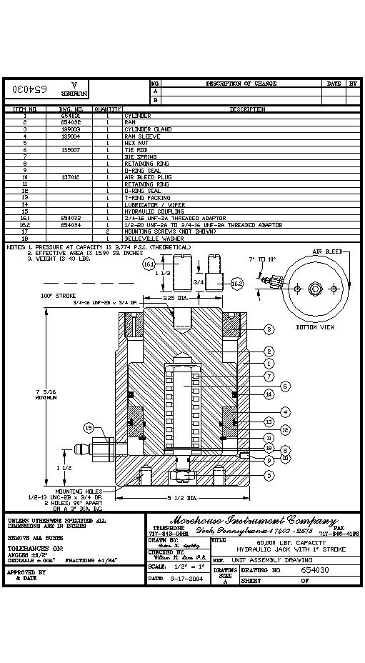
4 DRAWING A 4 4
5 ASSEMBLY INSTRUCTIONS 1.0 The Force Calibration Press is shipped assembled. 2.0 Remove the Calibration Press from the shipping crate and move it to the desired location. The Calibration Press weighs approximately 1600 pounds. The Calibration Press is designed to sit directly on the floor. 3.0 The hand pump has been fasten to the machine platen for shipping. Remover the hand pump from the platen by removing the two screws holding the hand pump drip pan to the platen. 4.0 The top surface of the platen and the unthreaded portion of the tie bars have been coated with a rust inhibitor. This is removed using mineral spirits. After the rust inhibitor has been removed these surfaces should be coated with light oil to prevent rust and corrosion. 5.0 Before using the Calibration Press the hydraulic force application system should be checked. 5.1 Check the hydraulic fluid in the hand pump by removing the fill plug. The fill plug should be left open about two turns during operation. If hydraulic fluid must be added be sure to use petroleum base anti-wear hydraulic fluid with an ISO Viscosity Grade of 22 or 32. The following hydraulic fluids are recommended, but any equal hydraulic fluid may be used: Arco Dutro AW 32 Conoco Super Hydraulic 32 Drydene Oil Co. Paradene 22AW Exxon Nuto H 32 Gulf Harmony 32 AW Mobil DTE 24 Texaco Rando HD Prepare the hydraulic jack for use. The hydraulic jack is furnished with a self sealing hose coupling and has been fully bled and checked at the factory prior to shipment. However, if the hand pump and hydraulic jack seem spongy during use there may be air in the system. If this occurs the system will need to be bled of entrapped air. This procedure is outlined in the Maintenance section of this manual. 5 5
6 OPERATING INSTRUCTIONS 1.0 Adjust the height of the cross head to allow space between the Calibrator s platen and the hydraulic ram for the load cell to be installed. To raise the crosshead turn the crank clockwise. To lower the crosshead turn the crank counter clockwise. (An optional electric motor to control the crosshead adjustment is available. This motor makes adjustment of the crosshead very easy. The motor operates on 115 volt, 60 cycle, single phase power. Contact Morehouse Instrument Co. for details.) 2.0 Fasten the base of the load cell to the hydraulic ram using the ¾-16 threaded adaptor. This adaptor has been screwed into the jack for shipping and should always be kept there when not in use. Be sure the load cell is turned completely into the threaded adaptor and there is no space between the base of the load cell and the hydraulic ram. The base of the load cell must be tight against the hydraulic ram. 3.0 Raise the adjustable crosshead and place the aircraft wheel platform scale to be calibrated on the Calibration Press s platen. The scale should be centered on the platen. 4.0 Use the appropriate loading blocks as specified by the calibration procedure for the scale to be calibrated. Center the six inch diameter compression pad supplied with the Calibration Press on the loading blocks. The side with the machined pocket should be up. Next place the load cell s load button on the six inch diameter compression pad. The load button should fit in the pocket machined in the six inch diameter compression pad. 5.0 Adjust the height of the crosshead so there is approximately 1/8 inch clearance between the spherical radius of the load button and the mating radius on the load cell. Be sure the load button is properly positioned to mate with the spherical radius of the load cell. 6.0 The desired forces are now applied to the Aircraft Wheel Platform Scale. The hand pump is used to activate the hydraulic jack. This pump functions similar to other hand pumps. With the pump connected to the hydraulic jack operating the hand lever causes hydraulic oil from the reservoir of the pump to be pumped to the hydraulic jack. During pump operation the fill plug on the upper right side of the pump body should be open about two turns to serve as a reservoir vent. To operate the hand pump the relief valve (item 20- hand pump drawing) must be closed. To close the relief valve turn the handle toward the hose connection of the pump body. 7.0 The hand pump is a dual volume design based on a double diameter piston. On the side of the hand pump is a valve rod (item 41-hand pump drawing). With the rod pulled out the full diameter of the piston is effective for low pressure, high volume pumping. With the rod pushed in the reduced diameter is effective for high pressure, low volume pumping with minimum effort. CAUTION: BEFORE PUSHING THE ROD IN RELEASE ANY DOWNWARD PRESSURE APPLIED TO THE HAND LEVER. 8.0 After the pressure has been pumped up with the hand lever to the approximate force desired use the star wheel (item 21-hand pump drawing) of the vernier screw piston to obtain and maintain the exact force required. CAUTION: DO NOT EXCEED THE ONE INCH STROKE OF THE JACK RAM OR CONSIDERABLE DAMAGE WILL RESULT. 9.0 To release the pressure after the desired forces have been applied turn the handle of the relief valve toward the back of the pump body. This will release pressure and the jack ram will return automatically. 6 6
7 MAINTENANCE INSTRUCTIONS 1.0 The top surface of the platen, the unthreaded portion of the tie bars, and the face of the jack ram should be kept coated with a light oil to prevent rust and corrosion. It is suggested these areas be wiped with light oil after each use. 2.0 The Calibration Press should be given a routine service inspection at regular intervals, the frequency of which depends upon how often and under what circumstances it is used. During this inspection, check the equipment for rust, leaking hydraulic fluid, and other visible signs of deterioration or damage. The inspection should include a visible inspection of all welds on the upper frame beam. Be sure to check all nuts, bolts, and screws to be sure they are tight. In addition, check the oil level in the pump reservoir, and examine the o-ring seals. Replace any ring that is split, cut, or otherwise damaged. Also, after an extended period of heavy service, it is advisable to disassemble and clean the pump. Cleaning the pump consists simply of washing or blowing out the body casting and washing the parts. Refer to Paragraph 6 for disassembly instructions. 3.0 Routine maintenance of the machine usually is limited to replacing o-ring seals in the pump assembly, adding hydraulic fluid if required, removing rust, dirt and corrosion from all assemblies, touching up paint damage, tightening any nuts or set screws which have loosened, and re-leveling. If the pump and jack assembly fail to develop or hold pressure, corrective maintenance may be necessary. (All numbers in parenthesis refer to items on the hand pump drawing.) 3.1 If the hand lever is operated and the pump fails to develop pressure, be sure the relief valve is closed and there is sufficient fluid in the reservoir. If failure continues one or both of the check valves (33 and 38) may be leaking. Replace both o-rings to be sure. 3.2 If the pump builds up pressure but the pressure drops, examine all joints for leakage; a very small amount of leakage will result in considerable loss of pressure. As the pressure drops, watch the hand lever. If it rises, the discharge check valve (33) is leaking. Replace the o-ring (29). If the hand lever does not rise as the pressure drops, then the relief valve is leaking. A foreign particle may be lodged on the seat, but more likely the o-ring (39) has failed and must be replaced. 3.3 The outlet in the pump body is tapped with 1/2" X 20 NF thread and machined for o-ring seals (15). A firm joint will prevent leakage. If leakage develops do not tighten the fitting excessively; replace the O-ring seal. CAUTION: DO NOT SCREW PIPE THREADS DIRECTLY INTO THE PUMP BODY OUTLET. THE SPECIAL ADAPTER (53) IS PROVIDED WITH PIPE THREADS FOR MAKING CONNECTIONS. 4.0 Routine lubrication consists of adding a few drops of oil to the chain drive on the upper frame and applying grease to any grease fittings. The grease used should conform to NLGI 2 specifications. 5.0 If the hand pump and hydraulic jack seem rather "spongy" during use there may be air in the system. If this occurs the system will need to be bled of entrapped air. To bleed the hydraulic jack, remove it from the Calibration Press and place it on its side on a bench or other suitable work surface, then proceed as follows: 5.1 Check the supply of fluid in the pump reservoir by removing the fill plug (item 30). The fill plug must be left open about two turns during operation to serve as a reservoir vent. If hydraulic fluid must be added be sure to use petroleum base anti-wear hydraulic fluid with an ISO Viscosity Grade of 22 or 32 as recommended in the Assembly Instructions. 7 7
8 5.2 With the hydraulic hose disconnected from the hydraulic jack and connected only to the hand pump, pump the hydraulic hose full of hydraulic fluid. The poppet of the hose half of the self-sealing quick-disconnect coupling must be depressed to accomplish this. 5.3 Connect the hydraulic hose to the jack cylinder fitting, and pump the jack ram out to full stroke, approximately 1 inch. 5.4 Roll the jack to bring the air bleed location to the highest point. 5.5 Alternately open the air bleed and roll the jack back and forth. The ram return spring will keep sufficient pressure on the fluid to purge the air. 5.6 After the jack has been bled of all entrapped air, tighten the air bleed securely, and return the jack to its original position on the Calibration Press. 6.0 Servicing the hand pump includes replacing the 0-rings, seals, and cleaning. When changing o-rings always lubricate the o-rings and all contacting metal parts before attempting assembly. For a lubricant, use the same fluid as will be used in the system. The high pressure valve poppet and retaining parts are held in place by the retaining plug (57). To reassemble, screw the retaining plug (57) into the body until all parts are solid, then back it off about two turns. This provides sufficient travel for the poppet. The valve rod (41) is held in place by three parts (25, 26, and 27) that must be removed to enable disassembly of the valve rod. Access to these three parts is gained by removing the reservoir (2). Be sure to drain the hydraulic fluid before removing the reservoir. The piston and hand lever can be removed as an assembly. Unscrew the cylinder retaining plug (16), disconnect from clevis (19), and pull straight up. At the end of the pressure stroke, the piston should bottom on the body plate (50) before the lever hits the cylinder retaining plug (16). If it does not, or more finger room between the hand lever and reservoir is desired, loosen piston pin (7), insert a small rod in the cross-hole provided in the piston, and back off the piston (which is threaded into the piston pin (17) as needed. Be sure to re-tighten the set screw (7). The cylinder pump (18) must be removed and reassembled from the top, otherwise, the o-ring will be cut by the angular, intersecting body casting bore. To remove the cylinder, detach the body plate (50) and push cylinder from the bottom. On reassembly, lubricate the o-rings and try to rotate the cylinder, as inserted, to avoid cutting or pinching the o-rings. A tapered piece of wood is helpful in rotating the cylinders. The precision pressure adjustment mechanism can be unscrewed from the pump body as a unit. The star wheel (21), star wheel pin (22), piston cap (23) and piston (24) make up a subassembly that is removed from the pump body by unscrewing the piston body (24). Note that the star wheel (21) is attached to the vernier piston (58) by means of a pin (22). 7.0 All parts of the Calibration Press (except o-rings and seals) are designed to last indefinitely in normal use. Inadvertent misuse or accidental damage may occur in which case repair may best be effected by replacing the damaged parts. 8 8
9 8.0 Parts lists, included in this manual, illustrate replacement parts available for the standard hand pump, hydraulic jack, and the Calibration Press. When ordering repair parts, please include the serial number of the Calibration Press (as engraved on the nameplate) and state the part number, name, and quantity required. Order parts from: Service Department Morehouse Instrument Company 1742 Sixth Avenue York, Pennsylvania U.S.A. 9 9
10 CERTIFICATE OF CAPACITY LOAD TEST AND OVERLOAD 60,000 LBS. AIRCRAFT SCALE FORCE CALIBRATION PRESS PART NUMBER THIS CERTIFIES THE AIRCRAFT SCALE FORCE CALIBRATION PRESS WAS TESTED FOR CAPACITY AND OVERLOAD. THE AIRCRAFT SCALE FORCE CALIBRATION PRESS WAS LOADED TO ITS RATED WORKING CAPACITY OF 60,000 LBS AND HELD FOR FIVE MINUTES. THE PRESS WAS ALSO PROOF LOADED TO 75,000 LBS, 25% ABOVE ITS WORKING CAPACITY
11 FRAME ASSEMBLY DRAWING
12 FRAME ASSEMBLY- PARTS LIST ITEM PART NO. NOMENCLATURE BASE PLATE-PLATEN BASE PLATE-REINFORCEMENT BASE PLATE-REINFORCEMENT TENSION TIE BAR SUPPORT B LEG KIT B FOOT PAD B 1 1/8-12 X 5 THREADED ROD *** 1 1/8-12 HEX JAM NUT *** ½ -13 X 1 SOC HD CAP SCREW *** ½ S.A.E. WASHER UPPER FRAME-GUSSET UPPER FRAME-SPROCKET RETAINER UPPER FRAME-BEAM TENSION TIE BARS COMPRESSION PAD (6 DIA.) COMPRESSION BLOCK (1 X 10 X 8 ) ROLLER CHAIN (NOT SHOWN) ,000 LBS. HYDRAULIC JACK ¾ -16 THREADED ADAPTOR ¾ -16 TO ½ -20 THREADED ADAPTOR ¼ HARDENED FLAT WASHER ¼-12 X 2 ½ HEX HEAD BOLT 49 *** GREASE FITTING 50 *** ¼ -20 X 1 ½ HEX HD CAP SCREW 51 *** ¼ S.A.E. WASHER A MOTOR MOUNTING PLATE 65 *** CIRCULAR LEVEL 66 *** NAME PLATE 67.L A LEFT HAND CHAIN GUARD 67.R A RIGHT HAND CHAIN GUARD 70 *** 120VOLT/60 HZ MOTOR 71 *** SWITCH BOX 72 *** POWER CABLE 77 *** ¼ -20 X 1 SOC HD CAP SCREW 80 *** 3 AMP CIRCUIT BREAKER 84 *** HYDRAULIC HAND PUMP 85 *** HYDRAULIC HOSE 86 *** HYDRAULIC COUPLING 87 *** ¼ -20 X ¼ PAN HD SCREW /8 TO ¾ FLEX COUPLING 89 *** TIE BAR ROLL PIN STOP MOTOR SPACERS 12 12
13 13 13
14 14 14
15 HAND PUMP PARTS LIST ITEM PART NO. NOMENCLATURE 1 T-575 RESERVOIR CAP 2 T-421 RESERVOIR TUBE 3 T-165 PUMP HANDLE 4 T-118 DRIP PAN 6 T-402 PUMP BODY 7 T-160 PISTON PIN SCREW 8 T-161 PISTON PIN SHOE 9 T-142 CLEVIS PIN 10 T-144 COTTER HAIR PIN CYLINDER BACK-UP RING (T-112) O-RING (T-153) PISTON BACK-UP RING (T-158) O-RING 16 T-108 CYLINDER RETAINING PLUG 17 T-145 PISTON PIN 18 T-236 CYLINDER PUMP 19 T-143 CLEVIS 20 T-773 RELIEF VALVE HANDLE 21 P STAR WHEEL 22 P STAR WHEEL PIN 23 1GT-33 PISTON CAP 24 1GT-32 PISTON BODY 25 T-405 SCREW 26 T-116 VALVE ROD SPRING 27 T-133 VALVE ROD DETENT PIN 28 T-117 PUMP BODY PLUG O-RING (T-152) 30 IGT-302 FILL AND VENT PLUG 31 T-127 CHECK VALVE SPACER 32 CV-1-5 CHECK VALVE SPRING 33 T-147 HIGH PRESSURE VALVE POPPET 34 T-406 DRIP PAN ATTACHING SCREW 35 T-167 DRIP PAN ATTACHING WASHER 36 T-110 RELIEF VALVE STEM 37 T-109 RELIEF VALVE BODY 15 15
16 ITEM PART NO. NOMENCLATURE 38 T-194 POPPET VALVE RELIEF VALVE O-RING (T-175) VALVE ROD O-RING (T-155) 41 T-115 VALVE ROD O-RING (T-151) 43 T-111 RELIEF VALVE SEAT RESERVOIR O-RING (T-156) 46 T-130 RESERVOIR STUD 47 P INLET TUBE 48 P-17-7 INLET TUBE FITTING 49 T-250 INLET TUBE NIPPLE 50 T-408 BODY PLATE CYLINDER O-RING (T-164) 52 T-106 PISTON 53 CV2SS2 SPECIAL ADAPTOR PISTON BACK-UP RING (T-159) 55 T-107 GUIDE ROD BODY ATTACHING SCREW 57 IGT-10 RETAINING PLUG 58 IGT-34 VERNIER PISTON SEAL RING PISTON 16 16
GH-BETTIS OPERATING & MAINTENANCE INSTRUCTIONS DISASSEMBLY & ASSEMBLY FOR THE T80X-M4-S DOUBLE ACTING SERIES HYDRAULIC ACTUATORS
 GH-BETTIS OPERATING & MAINTENANCE INSTRUCTIONS DISASSEMBLY & ASSEMBLY FOR THE T80X-M4-S DOUBLE ACTING SERIES HYDRAULIC ACTUATORS -S INDICATES CYLINDERS ARE IN TANDEM PART NUMBER: 100121 REVISION "A" ECN
SERVICE INSTRUCTIONS D TON
 1120 SOUTH CRYSTAL AVE * BENTON HARBOR MI PH: 269-925-7777 FAX: 269-925-6656 SERVICE INSTRUCTIONS D-51223 4 TON TO ASSEMBLE: 1. Check the handle set screw for tightness. CUSTOMER PRE-USE INSTRUCTIONS THE
High Lift Transmission Jack
 SPX Corporation 655 Eisenhower Drive Owatonna, MN 55060-0995 USA Phone: (507) 455-7000 Tech. Serv.: (800) 533-6127 Fax: (800) 955-8329 Order Entry: (507) 455-1480 Fax: (800) 283-8665 International Sales:
INSTALLATION, OPERATION AND MAINTENANCE MANUAL (IOM)
") INSTALLATION, OPERATION AND MAINTENANCE MANUAL (IOM) IOM-1088 03-16 Model 1088 Vacu-Gard Blanketing Valve ISO Registered Company SECTION I I. DESCRIPTION AND SCOPE The Model 1088 Vacu-Gard is a tank blanketing
INSTALLATION, OPERATION AND MAINTENANCE MANUAL (IOM) IOM-1088 03-16 Model 1088 Vacu-Gard Blanketing Valve ISO Registered Company SECTION I I. DESCRIPTION AND SCOPE The Model 1088 Vacu-Gard is a tank blanketing
GH-BETTIS SERVICE INSTRUCTIONS DISASSEMBLY & REASSEMBLY FOR MODELS HD521-M4, HD721-M4 AND HD731-M4 DOUBLE ACTING SERIES PNEUMATIC ACTUATORS
 GH-BETTIS SERVICE INSTRUCTIONS DISASSEMBLY & REASSEMBLY FOR MODELS HD521-M4, HD721-M4 AND HD731-M4 DOUBLE ACTING SERIES PNEUMATIC ACTUATORS WITH HYDRAULIC CONTROL PACKAGE PART NUMBER: SE-023 REVISION:
Operation & Service Manual
 Operation & Service Manual Model: 02-1248-0112 12 Ton Single Stage Jack 11/2004 Rev. 02 Includes Illustrated Parts Lists 1740 Eber Rd Tronair, Inc. Phone: (419) 866-6301 Holland, OH 43528-9794 www.tronair.com
INSTRUCTION MANUAL AND PARTS LIST FOR SERIES 8L-630J AND 630M WARNING
 INSTRUCTION MANUAL AND PARTS LIST FOR SERIES 8L-630J AND 630M WARNING READ CA-l AND TIDS INSTRUCTION MANUAL PRIOR TO INSTALLATION, OPERATION OR MAINTENANCE WARNING This Instruction Manual and General Instructions
SD Bendix E-10PR Retarder Control Brake Valve DESCRIPTION. OPERATION - Refer to Figure 2
 SD-03-832 Bendix E-10PR Retarder Control Brake Valve MOUNTING PLATE SUPPLY 4 PORTS ELECTRICAL AUXILIARY DESCRIPTION TREADLE RETARDER CONTROL SECTION EXHAUST DELIVERY 4 PORTS FIGURE 1 - E-10PR RETARDER
OPERATION & MAINTENANCE INSTRUCTIONS MODEL: TC-300
 1-800-223-4540 ** 602-437-5020 OPERATION & MAINTENANCE INSTRUCTIONS MODEL: TC-300 READ INSTRUCTIONS THOROUGHLY BEFORE OPERATING MACHINE Contents Safety Instructions Pg 3 Operating Instructions Pg 4-5 (Light
PACKING, HANDLING, TRANSPORTING AND STORING MOTORS
 PACKING, HANDLING, TRANSPORTING AND STORING MOTORS Make sure that the shaft of the motor is not loaded in any way and is protected from knocks. Axial loads or shocks may easily damage the bearings inside
BEHLEN DOUBLE ROW STRIP JOINING PRESS MODEL APSJ OPERATING INSTRUCTIONS & SERVICE INFORMATION
 BEHLEN DOUBLE ROW STRIP JOINING PRESS MODEL APSJ OPERATING INSTRUCTIONS & SERVICE INFORMATION NOTE: If Pink Sheets are included in this manual, refer to them for latest revisions. TECHNICAL INFORMATION
Property of American Airlines
 Date: September, 00 MALABAR INTERNATIONAL AIRCRAFT MAINTENANCE & SUPPORT EQUIPMENT READ AND SAVE THIS INSTRUCTION MANUAL OWNER'S MANUAL FOR MALABAR MODEL A SINGLE STAGE VARIABLE HEIGHT HYDRO - MECHANICAL
High Lift Transmission Jack
 655 Eisenhower Drive Owatonna, MN 55060 USA Phone: (507) 455-7000 Tech. Serv.: (800) 533-6127 Fax: (800) 955-8329 Order Entry: (800) 533-6127 Fax: (800) 283-8665 International Sales: (507) 455-7223 Fax:
High Lift Transmission Jack
 655 Eisenhower Drive Owatonna, MN 55060-0995 USA Phone: (507) 455-7000 Tech. Serv.: (800) 533-6127 Fax: (800) 955-8329 Order Entry: (800) 533-6127 Fax: (800) 283-8665 International Sales: (507) 455-7223
High Lift Transmission Jack Max. Capacity: kg (1,000 lbs.)
") 655 EISENHOWER DRIVE OWATONNA, MN 55060-0995 USA PHONE: (507) 455-7000 TECH. SERV.: (800) 533-6127 FAX: (800) 955-8329 ORDER ENTRY: (800) 533-6127 FAX: (800) 283-8665 INTERNATIONAL SALES: (507) 455-7223
655 EISENHOWER DRIVE OWATONNA, MN 55060-0995 USA PHONE: (507) 455-7000 TECH. SERV.: (800) 533-6127 FAX: (800) 955-8329 ORDER ENTRY: (800) 533-6127 FAX: (800) 283-8665 INTERNATIONAL SALES: (507) 455-7223
 DRUM BRAKE RIMS Periodic inspection of drum brake rims is necessary to determine indications of uneven or excessive wear. In general, brake rim failures other that regular wear are caused by brake linings
Fisher 2052 Diaphragm Rotary Actuator
 Instruction Manual 2052 Actuator Fisher 2052 Diaphragm Rotary Actuator Contents Introduction... 1 Scope of Manual... 1 Description... 1 Specifications... 4 Installation... 4 Actuator Mounting and Changing
TWO-STAGE HYDRAULIC PUMP. RWP55-IBT-Air
 ORIGINAL INSTRUCTIONS Form No.1000458 5 SPX Corporation 5885 11th Street Rockford, IL 61109-3699 USA Tech. Services: (800) 477-8326 Fax: (800) 765-8326 Order Entry: (800) 541-1418 Fax: (800) 288-7031 Internet
INSTRUCTIONS AND PARTS LIST FOR Models 6-225, 6-425, 6-250, 6-450, 6-275, 6-475, 6-650, and Air Hydraulic Presses
 INSTRUCTIONS AND PARTS LIST FOR Models 6-225, 6-425, 6-250, 6-450, 6-275, 6-475, 6-650, and 6-850 Air Hydraulic Presses WARNING LABELS To the left is the safety Alert symbol. When you see these safety
JARVIS. Model 30CL-1 AND 30CL-3 Hock Cutter and Dehorner. 30CL-1 Hock Cutter
 Model 30CL-1 AND 30CL-3 Hock Cutter and Dehorner 30CL-1 Hock Cutter with Leg Grabber 30CL-1 Hock Cutter 30CL-3 Dehorner Equipment Selection 30CL-1 Sheep Head Dropper Order Number 30CL-1 Hock Cutter 30CL-1
OWNER'S MANUAL HYDRAULIC DRUM STACKER MODEL HDC / 72 / 84 / 96
 VESTIL MANUFACTURING CORPORATION 999 North Wayne St. Angola, IN 03 Phone (0) 5-58 Fax (0) 5-339 E-mail: sales@vestil.com www.vestil.com Revised 008 A company dedicated to solving ergonomic and material
INSTRUCTIONS AND PARTS LIST FOR Models 8-025, 8-050, 8-075, and Elec-Draulic II Presses
 INSTRUCTIONS AND PARTS LIST FOR Models 8-025, 8-050, 8-075, and 8-150 Elec-Draulic II Presses SETTING UP THE PRESS FOR OPERATION For shipping convenience some of the parts are not assembled. Assemble these
TM-VE436MC.KIT. VE436MC Roll Grooving Tool WARNING EXPLODED VIEW OF SLIDE UPGRADE KIT SLIDE UPGRADE KIT INSTRUCTIONS
 5656 Rev. A R132460LBL 5655 Rev. A R129460LBL SLIDE UPGRADE KIT INSTRUCTIONS WARNING Read and understand all instructions before attempting to operate, adjust, or maintain any Victaulic grooving tools.
SAI GM Series Piston Hydraulic Motor Crankshaft Design Radial Piston Motors
 SAI GM Series Piston Hydraulic Motor Crankshaft Design Radial Piston Motors www.chinawinches.cn (Dimension: inch) Brief Performance Table of Sai GM Series Piston Hydraulic Motor (Full range GM05- GM9 series)
TSS Fit Kit Installation Instructions Timbersled Snow Bike System
 TSS Fit Kit Installation Instructions Timbersled Snow Bike System Information needed before you start: Read the entire installation instructions before starting. The instruction sheet is universal for
DP556 Pump. 55:1, Air-operated, Grease. General. Operation. Technical Data. Installation. Mounting with Reinforced Cover (Recommended)
") DP556 Pump 55:1, Air-operated, Grease General The DP556 Pump is a compressed air-operated reciprocating piston pump. This high capacity demand pump is compatible with mineral and synthetic grease and suitable
DP556 Pump 55:1, Air-operated, Grease General The DP556 Pump is a compressed air-operated reciprocating piston pump. This high capacity demand pump is compatible with mineral and synthetic grease and suitable
Installation Instructions
 Installation Instructions Rear Disc Brake Conversion Kit Item # RC4001, RC4001X Applications: Mopar 7.25, 8.25, 9.25 Axles Thank you for choosing Leed Brakes for your automotive product needs. Before you
SW14.5TI INTEGRAL HYDRAULIC FLANGE SPREADING WEDGE. Repair Manual INNOVATION IN ITS MOST FUNCTIONAL FORM
 SW14.5TI INTEGRAL HYDRAULIC FLANGE SPREADING WEDGE Repair Manual info@equalizerinternational.com www.equalizerinternational.com INNOVATION IN ITS MOST FUNCTIONAL FORM INDEX SECTION CONTENTS PAGE NO. 1
OWNER S TECHNICAL MANUAL
 OWNER S TECHNICAL MANUAL 2.5kg Grease Kit 6336 Description The Champion 6336 2.5kg grease kit is a manually operated, spring powered grease kit that comes complete with a hand piece. It is designed to
OWNER S TECHNICAL MANUAL. 6336N 2.5kg Grease Kit
 OWNER S TECHNICAL MANUAL 6336N 2.5kg Grease Kit 6336N Description The 6336N 2.5kg grease kit is a manually operated, spring powered grease kit with ergonomic, user friendly rod cap that comes complete
TT-12 OWNERS MANUAL/PARTS LIST
 TOPLIFTER Tailgates By THIEMAN TT-12 OWNERS MANUAL/PARTS LIST SHOWN WITH OPTIONAL 2 PC. ALUMINUM PLATFORM! IMPORTANT! KEEP IN VEHICLE! PLEASE READ AND UNDERSTAND THE CONTENTS OF THIS MANUAL BEFORE OPERATING
SERIES G3DB/AG3DB ELEVATOR
 TM INSTRUCTIONS AND PARTS LIST SERIES G3DB/AG3DB ELEVATOR WARNING This manual, and GENERAL INSTRUCTIONS MANUAL, CA-1, should be read thoroughly prior to pump installation, operation or maintenance. SRM00059
CAB TILT HYDRAULIC SYSTEM
 OPERATION, MAINTENANCE and SERVICE INSTRUCTIONS CAB TILT HYDRAULIC SYSTEM WITH POWER-PACKER PUMP, CYLINDERS and LATCHES A division of Actuant Corporation 1-800-745-4142 1 www.powerpackerus.com Notice The
INSTRUCTIONS AND PARTS LIST FOR Models 8-025, 8-050, 8-075, and Elec-Draulic II Presses
 INSTRUCTIONS AND PARTS LIST FOR Models 8-025, 8-050, 8-075, and 8-150 Elec-Draulic II Presses SETTING UP THE PRESS FOR OPERATION For shipping convenience some of the parts are not assembled. Assemble these
MODEL D-25S12-22-S POWER UNIT OPERATION, MAINTENANCE, AND REPAIR MANUAL
 MODEL D-25S12-22-S POWER UNIT OPERATION, MAINTENANCE, AND REPAIR MANUAL Introduction 1805 2 nd AVENUE NORTH * MOORHEAD, MN, USA 56560-2310 PHONE (218) 236-0223 * FAX (218) 233-5281 E-MAIL ADDRESS; info@portaco.com
HYDRAULICS. TX420 & & lower. Hydraulic Tandem Pump Removal. 4. Remove the LH side panel (Fig. 0388).
.") TX420 & 425 240000299 & lower 4. Remove the LH side panel (Fig. 0388). Hydraulic Tandem Pump Removal Note: Cleanliness is a key factor in a successful repair of any hydraulic system. Thoroughly clean all
TX420 & 425 240000299 & lower 4. Remove the LH side panel (Fig. 0388). Hydraulic Tandem Pump Removal Note: Cleanliness is a key factor in a successful repair of any hydraulic system. Thoroughly clean all
Model DFR 070/156/220 Rotary Actuator
 Figure 1 DFR 156 TABLE OF CONTENTS General 2 Actuator Assembly 18 Scope 2 Bushing / Yoke Assembly 18 Principles of Operation 2 Spring Barrel Assembly 18 Safety Caution 2 Diaphragm Plate Assembly 20 Specifications
ASSEMBLY INSTRUCTIONS FOR PART NUMBER GROUP
 ASSEMBLY INSTRUCTIONS FOR DYNAPRO 6 BIG BRAKE FRONT HAT KIT, 1.19 DIAMETER VENTED ROTOR 1990-005 ACURA/CIVIC ( LUG) 000-003 CIVIC SI ( LUG) 007 - PRESENT HONDA FIT FOR FACTORY 6 mm DISC SPINDLE PART NUMBER
S3 General Installation
 Wilfley Drylock Assembly General Installation Operating & General Servicing Clearance Settings Safety Precautions Spare Parts Ordering Assembly Instructions Model S3 General Installation Inspection upon
This file is available for free download at
 This file is available for free download at http://www.iluvmyrx7.com This file is fully text-searchable select Edit and Find and type in what you re looking for. This file is intended more for online viewing
Fisher 657 Diaphragm Actuator Sizes and 87
 Instruction Manual 657 Actuator (30-70 and 87) Fisher 657 Diaphragm Actuator Sizes 30 70 and 87 Contents Introduction... 1 Scope of Manual... 1 Description... 2 Specifications... 2 Installation... 3 Mounting
TECHNICAL SERVICE MANUAL
 Electronic copies of the most current TSM issue can be found on the Viking Pump website at www.vikingpump.com TECHNICAL SERVICE MANUAL HEAVY-DUTY Stainless steel BRACKET MOUNTED PUMPS SERIES 127 AND 4127
ASSEMBLY INSTRUCTIONS
 ASSEMBLY INSTRUCTIONS FOR FORGED SUPERLITE BIG BRAKE FRONT HUB KIT WITH 3.00 DIAMETER VENTED ROTOR 968-969 FORD MUSTANG (DISC BRAKE SPINDLE ONLY) PART NUMBER GROUP 0-950 WARNING INSTALLATION OF THIS KIT
EURO REEL
 Date Purchased Machine Serial No. Options The key number system in this parts book is arranged as follows: Please order parts by number - Key numbers with two circles denotes main assemblies. - Key numbers
Under Axle Jack Max. Capacity: 25 Tons
 SPX Corporation 655 Eisenhower Drive Owatonna, MN 55060-0995 USA Phone: (507) 455-7000 Tech. Serv.: (800) 533-6127 Fax: (800) 955-8329 Order Entry: (800) 533-6127 Fax: (800) 283-8665 International Sales:
TECHNICAL SERVICE MANUAL
 TECHNICAL SERVICE MANUAL HEAVY-DUTY bracket mounted PUMPS SERIES 4193 AND 493 SIZES GG - AL SECTION TSM 154 PAGE 1 of 10 ISSUE C CONTENTS Introduction....................... 1 Special Information...................
SD Bendix E-12 & E-15 Dual Brake Valve DESCRIPTION
 SD-03-6 Bendix E- & E-15 Dual Brake Valve TREADLE UPPER BODY ASSEMBLY PRIMARY DELIVERY ( ) 1 SECONDARY DELIVERY ( ) LOWER BODY ASSEMBLY MOUNTING PLATE PRIMARY SUPPLY ( SUP-1) PRIMARY SUPPLY ( SUP-) PRIMARY
Baumann Mikroseal Control Valve
 Instruction Manual 81000 Valve Baumann 81000 Mikroseal Control Valve Contents Introduction... 1 Scope of Manual... 1 Safety Precautions... 2 Maintenance... 3 Installation... 3 Air Piping... 4 Flow Direction...
TIN KNOCKER TK H1652 Hydraulic Shear
 TIN KNOCKER TK H1652 Hydraulic Shear INSTRUCTIONS & PARTS DIAGRAM TAAG INDUSTRIES CORP. 1550 SIMPSON WAY, ESCONDIDO, CA 92029 Tel: (800) 640-0746 Fax: (760) 727-9948 Website: www.tinknocker.com Email:
DO NOT INSTALL, OPERATE, OR MAINTAIN AN ATI PRODUCT UNLESS TRAINED AND QUALIFIED IN PRODUCT AND ACCESSORY INSTALLATION, OPERATION AND MAINTENANCE.
 IOM Supplement IOMS003 ATI HO1/HO2 HYDRAULIC OVERRIDE Scope of Supplement This supplement is intended to assist those who are involved with the installation, operation and maintenance of ATI Linear Actuators
ANDCO Eagle Actuator Instruction Manual
 ANDCO Actuators ANDCO Eagle Actuator Instruction Manual The information contained in this manual is essential to safe, successful, long term operation of your Andco Eagle Linear Actuator. Read and follow
OPERATING INSTRUCTIONS
 OPERATING INSTRUCTIONS When this Jack leaves the factory, the air release plug is closed to prevent the oil being spilled when the Jack is in transit. To simplify the air-venting of the oil chamber, a
MAINTAINING YOUR BEHLEN STITCHER
 MAINTAINING YOUR BEHLEN STITCHER Your Behlen stitcher was designed to give years of trouble free service. The design of your machine contains the best combination of function and reliability. In order
PRODUCT SERVICE MANUAL FOR BK12DHZ PUMPS
 PRODUCT SERVICE MANUAL FOR BK12DHZ PUMPS WARNING This manual, and the GENERAL INSTRUCTION MANUAL SRM00046, should be read thoroughly prior to pump installation, operation or maintenance. Manual No. SRM00095
Purging Air From Divider Block Lubrication Systems
 FROST ENGINEERING SERVICE Purging Air From Lubrication Systems A D I V I S I O N O F G E C S E Y S A L E S & S E R V I C E DESCRIPTION Divider block lubrication systems operate correctly only when all
Model Ton Hand Carry Axle Jack P/N: CJ67D0250-1
 Model 1504-50 15 Ton Hand Carry Axle Jack P/N: CJ67D0250-1 Operation and Maintenance Manual with Illustrated Parts List 2222 South Third Street Columbus, Ohio 43207-2402 Phone (614) 443-7492 FAX (614)
JARVIS. Model 30CL-1 and 30CL-3 Hock Cutter and Dehorner
 Model 30CL-1 and 30CL-3 Hock Cutter and Dehorner 30CL--1 Hock Cutter 30CL--1 Pistol Grip 30CL--3 Dehorner EQUIPMENT SELECTION... Ordering No. 30CL--1 Hock Cutter... 4025013 30CL--1 Hock Cutter with Grabber
EQUALIZER International Limited 10T(I) Integral Hydraulic Spreading Wedge Repair Instruction Manual
 Integral Hydraulic Spreading Wedge Repair Instruction Manual") EQUALIZER International Limited 10T(I) Integral Hydraulic Spreading Wedge Repair Instruction Manual INDEX THE EQUALIZER 10T(I) Integral Hydraulic Wedge SECTION CONTENTS PAGE NO (S) 03 04 05 06 07 08 09
EQUALIZER International Limited 10T(I) Integral Hydraulic Spreading Wedge Repair Instruction Manual INDEX THE EQUALIZER 10T(I) Integral Hydraulic Wedge SECTION CONTENTS PAGE NO (S) 03 04 05 06 07 08 09
H A R D E R D u m p B o x S p r e a d e r
 Serial Number: XXXXX O p e r a t o r s M a n u a l Model H A R D E R D u m p B o x S p r e a d e r Pg. 2 Pg. 2 Pg. 3 Pg. 4 Pg. 5 Pg. 6 Pg. 7 Pg. 9 Pg. 10 Pg. 10 INDEX Hydraulic Requirements Safety Safety
MODEL HD-BTC. Installation, Operation & Repair Parts Information REV041416
 MODEL HD-BTC Installation, Operation & Repair Parts Information REV041416 TABLE OF CONTENTS SAFETY INSTRUCTIONS 1 DEFINITIONS 1 SPECIFICATIONS 2 INSTALLATION INSTRUCTIONS 2 OPERATING INSTRUCTIONS 2 MAINTENANCE
PARTS MANUAL THIS PAGE INTENTIONALLY LEFT BLANK. Ag-Bag International, Ltd. G7000 June Appendix A
 The parts manual is organized into groups, it is designed to make the locating of parts easier. The exploded drawings also show assembly paths. All parts listed are available from your authorized Ag-Bag
Click Here for Printable PDF File. CHAPTER 3 - BASIC INFORMATION for PERFORMING HYDRAULIC SYSTEM MAINTENANCE
 HWH Online Technical School Lesson 1: Introduction to Hydraulics Chapter 3 - "BASIC INFORMATION for PERFORMING HYDRAULIC SYSTEM MAINTENANCE" (Filename: ML57000-012-CH3.DOC Revised: 22APR16) Click Here
Service Handbook HD /97
 Service Handbook HD 1050 5.905-032 07/97 Foreword HD 1050 Foreword Indispensable prerequisites for the competent execution of service procedures are comprehensive, real-life training workshops for technical
OWNER/OPERATOR MANUAL. Airmotor effective dia. in. 2.5
 MODELS 282050, 282716 & 283513 AIR OPERATED CHASSIS PUMP SERIES A OWNER/OPERATOR MANUAL SPECIFICATIONS Airmotor effective dia. in. 2.5 Airinlet Material outlet 1/4 NPTF 1/4 NPTF Liquid to Air Pressure
DP3 Pump. 3:1, Air-operated, Oil. General. Operation. Technical Data. Installation R0 10/09. 35a 35b 35c
 DP3 Pump 3:1, Air-operated, Oil General The DP3 Pump is a compressed air-operated piston reciprocating medium pressure pump. Suitable for medium flow transfer of high viscosity lubricants and for oil delivery
H. WEISS MACHINERY & SUPPLY
 PHONE: (718) 605-0395 - www.hweiss.com PEXTO PH52 HYDRAULIC SHEAR INSTRUCTIONS AND PARTS IDENTIFICATION MODEL PH52 ROPER WHITNEY 2833 HUFFMAN BLVD., ROCKFORD, ILLINOIS 61103-3990 * 815/962-3011 * FAX 815/962-2227
ASSEMBLY INSTRUCTIONS
 ASSEMBLY INSTRUCTIONS FOR DYNALITE PRO SERIES FRONT HUB KIT WITH.75 DIAMETER VENTED ROTOR 970-973 FORD MUSTANG (DRUM / DISC SPINDLE) PART NUMBER GROUP 0-905 WARNING INSTALLATION OF THIS KIT SHOULD ONLY
Baumann Sanitary Diaphragm Angle and Inline Control Valve
 Instruction Manual 84000 Valve Baumann 84000 Sanitary Diaphragm Angle and Inline Control Valve Contents Introduction... 1 Scope of Manual... 1 Safety Precautions... 2 Maintenance... 2 Flow Direction...
Installation, Operation and Maintenance Instructions
 Installation, Operation and Maintenance Instructions MODEL 5520 June 2002 1.0 GENERAL... 2 Model Number Information... 2 Features... 3 Specifications... 4 Table 1A. Flow Coefficients (C V ), Modified Percent
JARVIS. Model HTC -80 Hog Toe Cutter
 Model HTC -80 Hog Toe Cutter HTC -80 Standard HTC -80 Pistol Grip EQUIPMENT SELECTION... Ordering No. HTC--80 Standard... 4025061 HTC--80 Pistol Grip... 4025100 HTC--80 Pistol Grip Long... 4025114 without
4 - Way Control 4 - Way Control 4 - Way Control with lock
 INSTALLATION / OPERATION / MAINTENANCE 1. DESCRIPTION MODEL 0-02 (Full Internal Port) Powertrol Valve This manual contains information for installation, operation and maintenance of the Cla-Val Co. 0-02
UNIVERSAL CALIBRATING MACHINES
 FIGURE 1-100,000 lbf Morehouse Universal Calibrating Machine using a Morehouse Proving Ring to calibrate a Load Cell in compression. An optional Auxiliary Screw Pump is attached to Machine s upper platen.
ASSEMBLY INSTRUCTIONS FOR DYNALITE DRAG RACE FRONT HUB KIT WITH DIAMETER SOLID ROTOR PINTO / MUSTANG II
 ASSEMBLY INSTRUCTIONS FOR DYNALITE DRAG RACE FRONT HUB KIT WITH 0.75 DIAMETER SOLID ROTOR 97-978 PINTO / MUSTANG II (FIVE LUG CONFIGURATION ONLY)* PART NUMBER GROUP 0-03-B DISC BRAKES SHOULD ONLY BE INSTALLED
Tailgates By THIEMAN WT20, 30 & 40 PLEASE READ AND UNDERSTAND THE CONTENTS OF THIS MANUAL BEFORE OPERATING THE EQUIPMENT. HIEMAN
 WEIGHTLIFTER Tailgates By THIEMAN WT20, 30 & 40 OWNERS MANUAL/PARTS LIST! IMPORTANT! KEEP IN VEHICLE! PLEASE READ AND UNDERSTAND THE CONTENTS OF THIS MANUAL BEFORE OPERATING THE EQUIPMENT. NATIONAL TRUCK
Baumann Pneumatic Actuators
 Instruction Manual Baumann Pneumatic Actuators Baumann Pneumatic Actuators Contents Introduction... 1 Scope of Manual... 1 Design Notes... 2 Installation... 2 Attaching an Air-to-Retract (ATR) Actuator
Pressure Relief Valve Maintenance Manual
 Technical Manual 1098T Pressure Relief Valve Maintenance Manual Farris Engineering Division of Curtiss-Wright Flow Control Corporation TABLE OF CONTENTS - Manual Revision 0 Introduction & Safety Tips...
STACKER INSTRUCTION MANUAL
 STACKER INSTRUCTION MANUAL The Mobile Stackers are lifting devices featuring easy, flexible, reliable and safe operation suitable for transportation of loads in such applications as warehouses, manufacturing
Hydraulic Hand Pallet Trucks
 Operating Instructions & Parts Manual 12U124 Please read and save these instructions. Read carefully before attempting to assemble, install, operate, or maintain the product described. Protect yourself
Installation Instructions
 Installation Instructions Rear Disc Brake Conversion Kit Item # RC1001, RC1001X Applications: 64-72 A-body, 67 F-Body, 63-67 X-body with Non Staggered Shocks Thank you for choosing GPS Auto for your automotive
Wind Driven Motorcycle Chain Lubricator- Installation and Operation
 1. Preparation a. Before beginning the installation it is recommended that you review installation videos at Motobriiz Installation- YouTube i. These videos not only show a typical installation, but also
Valtek Auxiliary Handwheels and Limit Stops
 Valtek Auxiliary s and Limit Stops Table of Contents Page 1 General information 2 Installation 2 Side-mounted handwheels, size 25 and 50 (linear actuators) 3 Side-mounted handwheels, size 100 and 200 (linear
NECO Pumping Systems
 INSTALLATION OPERATION & MAINTENANCE INSTRUCTIONS For Your NECO Pumping Systems PACKAGED CIRCULATING SYSTEM THIS COMPLETELY ASSEMBLED, TESTED, PACKAGED CIRCULATING SYSTEM IS OF THE HIGHEST QUALITY AND
INSTALLATION INSTRUCTIONS REPAIR SEAL KIT PowerSurvivor 160E
 INSTALLATION INSTRUCTIONS REPAIR SEAL KIT PowerSurvivor 160E PURPOSE OF THE KIT The Repair Seal Kit should be installed after 500 hours of operation. It should be installed regardless of whether or not
ONYX VALVE CO MODEL DAO-PFC Installation & Maintenance
 ONYX VALVE CO MODEL DAO-PFC Installation & Maintenance OPERATION: (4-2010) The Onyx DAO-PFC pinch valve is an open frame valve without housing enclosure and fails closed on loss of air. The actuator drives
20 TONNE HYDRAULIC PRESS MODEL NO: CSA20FBT
 20 TONNE HYDRAULIC PRESS MODEL NO: CSA20FBT PART NO: 7614058 OPERATION & MAINTENANCE INSTRUCTIONS WARNING: Read these instructions before using the press GC0516 INTRODUCTION Thank you for purchasing this
Operation & Service Manual
 Operation & Service Manual Technical Manual Model: 02-7813C0100 12 Ton (10.8 Metric Ton) Two Stage Hydraulic Axle Jack 06/2006 Rev. OR Includes Illustrated Parts List Tronair, Inc. 1740 Eber Road Holland,
DP5 Pump. 5:1, Air-operated, Heavy Duty, Oil. General. Operation. Technical Data. Installation R1 09/10
 DP5 Pump 5:1, Air-operated, Heavy Duty, Oil General The DP5 Pump is a compressed air-operated reciprocating piston medium pressure pump. These pumps are suitable for distribution of all types of light
Installation Instructions
 Installation Instructions Rear Disc Brake Conversion Kit Item # RC2001, RC2001X Applications: Mopar 8-3/4 & 9-3/4 Rear Axles Thank you for choosing Leed Brakes for your automotive product needs. Before
Racing Jack Max. Capacity: 3,000 lbs. (1,361 kg)
") R SPX Corporation 655 Eisenhower Drive Owatonna, MN 55060-0995 USA Phone: (507) 455-7000 Tech. Serv.: (800) 533-6127 Fax: (800) 955-8329 Order Entry: (800) 533-6127 Fax: (800) 283-8665 International Sales:
R SPX Corporation 655 Eisenhower Drive Owatonna, MN 55060-0995 USA Phone: (507) 455-7000 Tech. Serv.: (800) 533-6127 Fax: (800) 955-8329 Order Entry: (800) 533-6127 Fax: (800) 283-8665 International Sales:
Installation Instructions RD/HD
 FISHER ENGINEERING P.O. Box 529 Rockland, Maine 04841 27000 RD/HD 27200 RD/HD August 1, 2001 Lit. No 26916 Installation Instructions 27000 RD/HD Table of Contents Safety Information... 2 Blade, Headgear,
Service Jacks. Operating Instructions & Parts Manual. Model Number. Capacity 4 Ton 4 Ton Air/ Manual 10 Ton 10 Ton Air/ Manual HW93657/ HW93660
 Service Jacks Operating Instructions & Parts Manual Model Number HW93657 HW93667 HW93660 HW93662 Capacity 4 Ton 4 Ton Air/ Manual 10 Ton 10 Ton Air/ Manual Made in North America HW93657/ HW93660 HW93667/
INSTALLATION INSTRUCTIONS
 INSTALLATION INSTRUCTIONS REAR DISC CONVERSION KIT A128-4 1997-2004 JEEP WRANGLER (TJ) WITH DANA 44 AXLES (non-abs) Thank you for choosing STAINLESS STEEL BRAKES for your braking needs. Pleases take the
INSTALLATION INSTRUCTIONS
 INSTALLATION INSTRUCTIONS REAR DISC CONVERSION KIT A136-1 1976-86 AMC 20 AXLES WITH WARN FULL FLOATING AXLE CONVERSION Thank you for choosing STAINLESS STEEL BRAKES CORPORATION for your braking needs.
SD Bendix Manual Slack Adjusters DESCRIPTION ADJUSTING MECHANISM OPERATION
 SD-05-1200 Bendix Manual Slack Adjusters WORM SHAFT (LOCK SCREW) FIGURE 1 - POSITIVE LOCK TYPE SLACK ADJUSTER DESCRIPTION In an s-cam type foundation brake, the final link between the pneumatic system
CONTENTS. Product Features and Specifications Installation Requirement Installation Exploded View Operation Instruction...
 1 CONTENTS Product Features and Specifications... 3 Installation Requirement... 5 Installation... 6 Exploded View... 20 Test... 22 Operation Instruction... 25 Maintenance... 26 Trouble Shooting... 27 Parts
Baumann Sanitary Angle Control Valve
 Baumann 83000 Sanitary Angle Control Valve Contents Introduction... 1 Scope of Manual... 1 Safety Precautions... 2 Educational Services... 2 Maintenance... 3 Installation... 3 Air Piping... 4 Flow Direction...
CHASSIS CONTENTS EXTERIOR PARTS 6-1 FRAME COVER 6-2 REAR FRAME COVER 6-4 FRONT WHEEL 6-6 FRONT BRAKE 6-10 HANDLEBARS 6-17 FRONT FORK 6-19
 CHASSIS CONTENTS EXTERIOR PARTS 6- FRAME COVER 6- REAR FRAME COVER 6-4 FRONT WHEEL 6-6 FRONT BRAKE 6-0 HANDLEBARS 6-7 FRONT FORK 6-9 STEERING 6-6 REAR WHEEL 6-3 REAR BRAKE 6-39 6 REAR SHOCK ABSORBER 6-43
DeZURIK " BAW AWWA BUTTERFLY VALVES WITH EPOXY-RETAINED SEAT
 DeZURIK 20 144" BAW AWWA BUTTERFLY VALVES WITH EPOXY-RETAINED SEAT Instruction D10373 April 2017 Instructions These instructions provide information about the 20 (250 F2 model only) and the 24-144 BAW
TC20 Chain Driven Power Take-Off Overhaul Instructions
 TC20 Chain Driven Power Take-Off Overhaul Instructions Table of Contents Section Page Introduction 4 Ordering Repair Parts 4 General Information 5 Special Tools 6 Disassembly See Page 2 Reassembly See
Type 644 and 645 Differential Pressure Pump Governors
 Instruction Manual 644 and 645 Pump Governors Type 644 and 645 Differential Pressure Pump Governors Introduction Scope of Manual This instruction manual provides information on installation, adjustment,