OPERATION & MAINTENANCE INSTRUCTIONS MODEL: TC-300
|
|
|
- Rodney Cummings
- 6 years ago
- Views:
Transcription


1 ** OPERATION & MAINTENANCE INSTRUCTIONS MODEL: TC-300 READ INSTRUCTIONS THOROUGHLY BEFORE OPERATING MACHINE
2 Contents Safety Instructions Pg 3 Operating Instructions Pg 4-5 (Light Passenger Tires) Operating Instructions Pg 6 (Light Truck Tires) Maintenance Procedures Pg 7-8 Roller Table Kit Pg 9-10

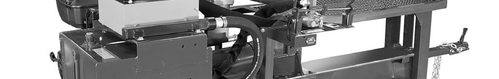
3 SAFETY INSTRUCTIONS WARNING: Only personnel trained in the operation of the TC-300 should be operating this machine. Thoroughly read all safety and operating instructions before using this machine. GENERAL: NEVER wet engine, motor, switch box or hydraulic controls. Cover these items if the machine is to be washed. Always disconnect electrical power before attempting maintenance. Gasoline or Diesel engines please refer to the specified engine manuals supplied by these companies. Gasoline Installation STANDARD 18 H.P. Briggs & Stratton Vanguard with electric start. Electrical Installation: The TC-300 Electric requires a minimum of 50 AMP, 230 volt, 60 cycle at the machine. The TC-300 Electric is equipped with a 10 HP, 230/460 volt, 60 cycle standard. Caution: Motor rotation must be clockwise when looking at the end of motor. If electric motor runs counter-clockwise, reverse the wires as indicated on the motor plate diagram Hyd. Oil Cooler Hyd. Filler Breather Hyd. Oil Filter Hyd. Pressure Gauge 2-Handle Hyd. Control Valve Protective Guard Stationary Crushing Frame Power Source 2 Ball Hitch 30 Gal Oil Reservoir Safety Chains Fender Front Supt Jack Rear Bumper Movable Wedge Main Support Beam Hydraulic Cylinder 13 Tire & Spoked Wheels Torsion Axles 3


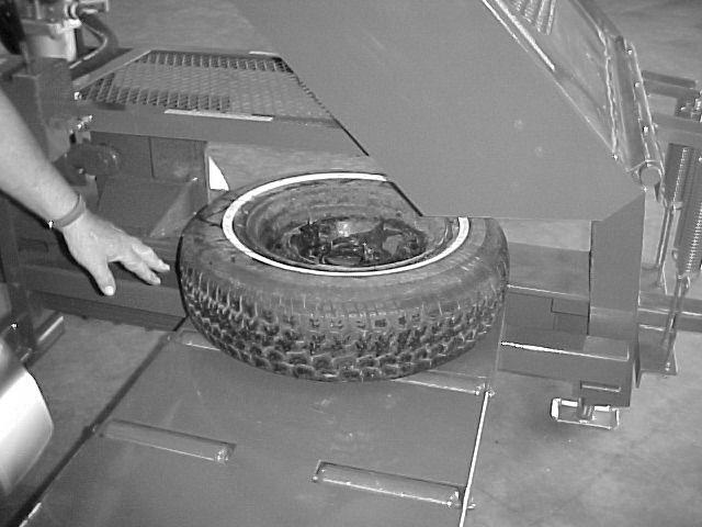
4 OPERATING INSTRUCTIONS 1 2 Position TC-300 near tire and wheel supply to be crushed. Place front support jack in position. Crank jack to bring TC-300 main beam to approximate level position. 3 Check engine for oil and fuel levels. Turn on fuel valve, start engine using manufacturers operating instructions. Check to be sure breather is installed in top of hydraulic reservoir. 4 When crushing wheels, run engine at 3/4 open throttle. 5 Place tire & wheel into the TC-300 crushing chamber. Place wheel with valve stem facing up. NOTE: It is Center wheel over beam. 6 Position tire to the front against the crushing frame as shown. recommended that air be vented from tire. 4


5 OPERATING INSTRUCTIONS 7 Operate Hydraulic valve handles. Pull valve handles towards operator to crush wheel. Push valve handles away from operator to return crushing wedge to starting position. 8 This photo illustrates the wheel being partially crushed This photo illustrates the wheel being fully crushed. Operate Hydraulic valve handles to return crushing wedge to the starting position. 11 Slide the wheel and tire out of the TC-300 chamber. NOTE: The wheel & tire can be taken out of either side of the machine 12 This photo illustrates the wheel crushed and separated from the tire. 5


6 OPERATING INSTRUCTIONS Light Truck Tires 1 Place tire & wheel into the TC-300 crushing chamber. Place wheel with valve stem facing up. NOTE: It is Center wheel over beam. 2 Position tire to the front against the crushing frame as shown. recommended that air be vented from tire. 3 4 This photo illustrates the wheel being fully crushed. Operate Hydraulic valve handles to return crushing wedge to the starting position. 5 Slide the wheel and tire out of the TC-300 chamber. NOTE: The wheel & tire can be taken out of either side of the machine NOTE: If the light truck wheel is a lock ring style always place lock ring down against the beam 6 This photo illustrates the wheel crushed and separated from the tire. 6


7 MAINTENANCE 1 2 The Hour Meter indicates elapsed hours for proper engine maintenance service intervals. Periodically insert grease at the cylinder pivot. 3 Before daily operation check all bolts for tightness on the movable wedge. This adjustment controls low to high pressure shift point. If motor bogs down loosen lock nut & turn Allen screw counter clockwise 1/2 turn and retry 5 Once every 6 months, remove wheels & hubs from axle and pack the wheel bearings with a wheel bearing grease. 4 6 This photo illustrates the Oil filter location on the engine. Replace filter every 6 months for smooth engine operation NOTE: Review Engine Manufacturer s manual for more info on servicing engines 7


8 MAINTENANCE 7 8 This photo illustrates the adjustment location of the hydraulic pump pressure to the valve. The gauge should read PSI when the ram is fully extended. To increase pressure, first remove large Hex nut. Then using a Hex Allen wrench turn adjustment screw to the right 1/4 turn at a time & recheck until pressure is PSI. Every 6 months check battery condition 9 10 The crushing wedge has space wear bars on both the upper and lower slides. These wear bars may need adjusting. Loosen 6 upper and 6 lower cap screws and slide wear bars up to beam flange. Leave 1/32 clearance between beam and wear bar. If wear bars are worn too much, remove bars and turn side to side. This will give a new side to guide on. DO NOT ALLOW SLIDE BOLTS TO LOOSEN. KEEP BOLTS TIGHT TO 100 FT-LBS & ADJUST SLIDE PLATES IF NECESSARY. Replace oil filer every 6 months. Use TSI P/N 10130E for the replacement element Detent Check hydraulic oil reservoir level by viewing the sight glass. Oil level should be approximately 3 5 from the top. NOTE: HYDRAULIC FLUID SHOULD BE DRAINED AND REFILLED EVERY 6 MONTHS. USE UNIVERSAL AUTOMATIC TRANSMISSION FLUID SAE 20 OR SAE 30 If the valve kicks out on the arms return stroke, the detent will have to be tightened slightly. Loosen lock nut as shown. Tighten outer nut 1/4 turn and tighten lock nut. Continue to crush. If it kicks out again, readjust it another 1/4 turn. 8


9 OPTIONS ROLLER TABLE KIT TSI #6114 9
10 10
Type 2 Push-Through 37 Ton Log Splitter. Assembly Manual
 Type 2 Push-Through 37 Ton Log Splitter Assembly Manual Refer to this manual for the following models: RS37PT-LF09PC-16-1 RS37PT-LF09EC-16-1 RS37PT-LF09EC-16-2 RS37PT-LF13EC-22-1 RS37PT-LF13EC-22-2 RS37PT-LF15EC-22-1
Final Assembly Instructions Casco Bay Cruiser
 Final Assembly Instructions Casco Bay Cruiser Thank you for buying your new bicycle from L.L.Bean. Read these instructions carefully before beginning the final assembly. Prior to shipping, our expert cycling
Final Assembly Instructions Portside Cruiser
 Final Assembly Instructions Portside Cruiser Thank you for buying your new bicycle from L.L.Bean. Read these instructions carefully before beginning the final assembly. Prior to shipping, our expert cycling
DVX 300 Euro. Model Number A2012KSF2BEUK SHARE OUR PASSION.
 ATV 2012ATV Illustrated Parts Manual DVX 300 Euro Model Number A2012KSF2BEUK TM SHARE OUR PASSION. TABLE OF CONTENTS 2012 ATV DVX 300 Euro (Model No. A2012KSF2BEUK) BODY PANEL AND HEADLIGHT ASSEMBLY...
INFEED HOPPER COMPONENTS. Parts may not be exactly as shown. Bandit. Copyright 1/12
 INFEED HOPPER COMPONENTS 80 INFEED HOPPER COMPONENTS 1. 626-200019 Folding Pan for Infeed Hopper 2 a. 900-4901-83 Folding Pan Spring Lock & Trap Door Lock b. 900-7900-93 Black Rubber Cap (Not Shown) 3
ATV 300 DVX CAT GREEN (A2011KSF2BUSZ) Page 1 of 56 AIR INTAKE ASSEMBLY
 Page 1 of 56 AIR INTAKE ASSEMBLY") 2011 ATV 300 DVX CAT GREEN (A2011KSF2BUSZ) Page 1 of 56 AIR INTAKE ASSEMBLY 2011 ATV 300 DVX CAT GREEN (A2011KSF2BUSZ) Page 2 of 56 AIR INTAKE ASSEMBLY Ref # Part Number Qty S/P/F Description 1 3303-705
2011 ATV 300 DVX CAT GREEN (A2011KSF2BUSZ) Page 1 of 56 AIR INTAKE ASSEMBLY 2011 ATV 300 DVX CAT GREEN (A2011KSF2BUSZ) Page 2 of 56 AIR INTAKE ASSEMBLY Ref # Part Number Qty S/P/F Description 1 3303-705
READ INSTRUCTIONS THOROUGHLY BEFORE OPERATING TC-6 TC-15 TC Fax
 OPERATING MANUAL TC-6, TC-15A & TC16 FILTER CRUSHER TC-6 TC-15 TC-16 READ INSTRUCTIONS THOROUGHLY BEFORE OPERATING Oct. 18, 2012 800.223.4540 3451 S. 40th Street Phoenix, AZ 85040 602.437.5020 www.tssissg.com
Illustrated Parts Manual. Model Number A2011KSF2BEUZ (Black-Cat Green) A2011KSF2BEOJ (White-Cat Green)
 A2011KSF2BEOJ (White-Cat Green)") Illustrated Parts Manual 2 1 10 DVX 300 Euro Model Number A2011KSF2BEUZ (Black-Cat Green) A2011KSF2BEOJ (White-Cat Green) S H A R E O U R PAS S IO N. TM TABLE OF CONTENTS 2011 ATV DVX 300 Euro Black-Cat
Illustrated Parts Manual 2 1 10 DVX 300 Euro Model Number A2011KSF2BEUZ (Black-Cat Green) A2011KSF2BEOJ (White-Cat Green) S H A R E O U R PAS S IO N. TM TABLE OF CONTENTS 2011 ATV DVX 300 Euro Black-Cat
'99-03 CHEVROLET/GMC IFS 4WD 6" SUSPENSION SYSTEM P/N INSTALLATION INSTRUCTIONS
 1/16/04 '99-03 CHEVROLET/GMC IFS 4WD 6" SUSPENSION SYSTEM P/N. 10-41099 INSTALLATION INSTRUCTIONS NOTE: Each Lift Kit and options to Lift Kits are packaged separately. Therefore, installation procedures
X4 (GREEN) (A2000ATF2AUSG) Page 1 of 80 AIR INTAKE ASSEMBLY
 (A2000ATF2AUSG) Page 1 of 80 AIR INTAKE ASSEMBLY") 2000 300 2X4 (GREEN) (A2000ATF2AUSG) Page 1 of 80 AIR INTAKE ASSEMBLY 2000 300 2X4 (GREEN) (A2000ATF2AUSG) Page 2 of 80 AIR INTAKE ASSEMBLY Ref # Part Number Qty S/P/F Description 1 3570-001 1 /P Intake,
2000 300 2X4 (GREEN) (A2000ATF2AUSG) Page 1 of 80 AIR INTAKE ASSEMBLY 2000 300 2X4 (GREEN) (A2000ATF2AUSG) Page 2 of 80 AIR INTAKE ASSEMBLY Ref # Part Number Qty S/P/F Description 1 3570-001 1 /P Intake,
MOREHOUSE INSTRUMENT COMPANY, INC. 60,000 LBS CAPACITY AIRCRAFT PART NUMBER SCALE S FORCE CALIBRATION PRESS PART NO.
 INDEX 1. GENERAL SPECIFICATION AND DRAWING 804000-03... 2 2. ASSEMBLY INSTRUCTIONS... 5 3. OPERATING INSTRUCTIONS... 6 4. MAINTENANCE INSTRUCTIONS... 7 5. CERTIFICATE OF CAPACITY LOAD TEST AND OVERLOAD...
Sherco Setup and Lubrication Guide
 Sherco Setup and This guide is designed to provide the Sherco owner with instructions on how to: Set up a new bike Clean and re-oil the air filter Change the transmission oil Change the fork oil Repack
Model ET 5000W Operation and Service Manual
 Model ET 5000W Operation and Service Manual Patented 5/16 BALL Load Capacity: 5000 lbs The ET 5000W ESCALATE TRAILER offers ground level roll-on loading and roll-off unloading of equipment with non-tilting
ATV I l. l u. r a. Parts Manual ARCTIC CAT. 250 cc/300 cc
 2000 I l l u st ATV 250 cc/300 cc Model No. A2000ATE2AUSG (250 - Green) Model No. A2000ATE2AUSR (250 - Red) Model No. A2000ATF2AUSG (300 2x4 - Green) Model No. A2000ATF2AUSR (300 2x4 - Red) Model No. A2000ATF4AUSG
DVX 90 MODEL NUMBER A2008KSB2BUSD (BLACK-RED) MODEL NUMBER A2008KSB2BUSE (BLACK-CAT GREEN) MORE TO GO ON. TM
 MODEL NUMBER A2008KSB2BUSE (BLACK-CAT GREEN) MORE TO GO ON. TM") 2008 DVX 90 Illustrated Parts Manual MODEL NUMBER A2008KSB2BUSD (BLACK-RED) MODEL NUMBER A2008KSB2BUSE (BLACK-CAT GREEN) MORE TO GO ON. TM TABLE OF CONTENTS Black-Red (Model No. A2008KSB2BUSD) Black-Cat
2008 DVX 90 Illustrated Parts Manual MODEL NUMBER A2008KSB2BUSD (BLACK-RED) MODEL NUMBER A2008KSB2BUSE (BLACK-CAT GREEN) MORE TO GO ON. TM TABLE OF CONTENTS Black-Red (Model No. A2008KSB2BUSD) Black-Cat
Log Splitter. Model No Serial No and Up Model No HD Serial No and Up * * A
 Form No. 3412-345 Rev A Log Splitter Model No. 22618 Serial No. 400000000 and Up Model No. 22618HD Serial No. 400000000 and Up Register at www.toro.com. Original Instructions (EN) *3412-345* A Ordering
Please read all instructions before operation!!
 1 Flow Rate: 8gpm Pressure Range: 0-2000psi RPM: 60 (load free) Torque: 600 ft lb HP: 13 Honda Engine Features: Auxiliary Flat Faced Male and Female Quick Disconnects Ship Weight: 510 lbs Reservoir Capacity:
Final Assembly Instructions: Bikes with Threadless Headsets
 Final Assembly Instructions: Bikes with Threadless Headsets Thank you for buying your new bicycle from L.L.Bean. Read these instructions carefully before beginning the final assembly. Prior to shipping,
 Manufacturers of Patented Truck Trailering Lifts 16 W. West Hill Road Barkhamsted, CT 06063. Ph. 860-379-7772 or 1-800-450-8659 Fax 860-738-2777 WWW.TRUHITCH.COM INFO@TRUHITCH.COM 1 Read All Instructions
Model Repair Parts Sheet SPECIFICATIONS. Stake threads lightly after assembly. Note: Pump base is not available as a service item.
 Repair Parts Sheet Model 10508 SPECIFICATIONS Operating Pressure Relief Valve Setting Oil Volume per Stroke Reservoir Capacity 10,000 psi max. 10,000 psi 0.1595 cu. in. 43 cu. in. Use a 3/16 hex wrench
CHASSIS CONTENTS EXTERIOR PARTS 6-1 FRAME COVER 6-2 REAR FRAME COVER 6-4 FRONT WHEEL 6-6 FRONT BRAKE 6-10 HANDLEBARS 6-17 FRONT FORK 6-19
 CHASSIS CONTENTS EXTERIOR PARTS 6- FRAME COVER 6- REAR FRAME COVER 6-4 FRONT WHEEL 6-6 FRONT BRAKE 6-0 HANDLEBARS 6-7 FRONT FORK 6-9 STEERING 6-6 REAR WHEEL 6-3 REAR BRAKE 6-39 6 REAR SHOCK ABSORBER 6-43
Final Assembly Instructions: Runaround Cruiser
 Final Assembly Instructions: Runaround Cruiser Thank you for buying your new bicycle from L.L.Bean. Read these instructions carefully before beginning the final assembly. Prior to shipping, our expert
ATV 90 UTILITY GREEN (A2006KUB2BUSG) Page 1 of 60 AIR INTAKE ASSEMBLY
 Page 1 of 60 AIR INTAKE ASSEMBLY") 2006 ATV 90 UTILITY GREEN (A2006KUB2BUSG) Page 1 of 60 AIR INTAKE ASSEMBLY 2006 ATV 90 UTILITY GREEN (A2006KUB2BUSG) Page 2 of 60 AIR INTAKE ASSEMBLY Ref # Part Number Qty S/P/F Description 1 3303-005
2006 ATV 90 UTILITY GREEN (A2006KUB2BUSG) Page 1 of 60 AIR INTAKE ASSEMBLY 2006 ATV 90 UTILITY GREEN (A2006KUB2BUSG) Page 2 of 60 AIR INTAKE ASSEMBLY Ref # Part Number Qty S/P/F Description 1 3303-005
Installation Instructions (Page 1)
") Installation Instructions (Page 1) Front Parts List: Tools Required: 2 2.5 Front Shocks (25001-373 0-2.5 Lift OR 25001-375 3-5 Lift) Floor Jack/Jack Stands 2 Front Reservoir Brackets (25044-021L/22R) Metric
Installation Instructions (Page 1) Front Parts List: Tools Required: 2 2.5 Front Shocks (25001-373 0-2.5 Lift OR 25001-375 3-5 Lift) Floor Jack/Jack Stands 2 Front Reservoir Brackets (25044-021L/22R) Metric
ATV 90 UTILITY CALIFORNIA GREEN (A2008KUB2BCAG) Page 1 of 58 AIR INTAKE ASSEMBLY
 Page 1 of 58 AIR INTAKE ASSEMBLY") 2008 ATV 90 UTILITY CALIFORNIA GREEN (A2008KUB2BCAG) Page 1 of 58 AIR INTAKE ASSEMBLY 2008 ATV 90 UTILITY CALIFORNIA GREEN (A2008KUB2BCAG) Page 2 of 58 AIR INTAKE ASSEMBLY Ref # Part Number Qty S/P/F Description
2008 ATV 90 UTILITY CALIFORNIA GREEN (A2008KUB2BCAG) Page 1 of 58 AIR INTAKE ASSEMBLY 2008 ATV 90 UTILITY CALIFORNIA GREEN (A2008KUB2BCAG) Page 2 of 58 AIR INTAKE ASSEMBLY Ref # Part Number Qty S/P/F Description
HYDRAULICS. TX420 & & lower. Hydraulic Tandem Pump Removal. 4. Remove the LH side panel (Fig. 0388).
.") TX420 & 425 240000299 & lower 4. Remove the LH side panel (Fig. 0388). Hydraulic Tandem Pump Removal Note: Cleanliness is a key factor in a successful repair of any hydraulic system. Thoroughly clean all
TX420 & 425 240000299 & lower 4. Remove the LH side panel (Fig. 0388). Hydraulic Tandem Pump Removal Note: Cleanliness is a key factor in a successful repair of any hydraulic system. Thoroughly clean all
90 Utility Model Number A2013KUB2BUSZ SHARE OUR PASSION.
 2013 90 Utility Model Number A2013KUB2BUSZ TM SHARE OUR PASSION. TABLE OF CONTENTS 2013 ATV 90 (Model No. A2013KUB2BUSZ) BODY PANEL AND HEADLIGHT ASSEMBLY... 1 FRONT AND REAR RACK ASSEMBLY... 2 FRAME AND
400 4x4 Euro MODEL NUMBER A2008IDG4BEUR (RED) MODEL NUMBER A2008IDG4BEUG (GREEN) MODEL NUMBER A2008IDG4BEUZ (CAT GREEN) MORE TO GO ON.
 MODEL NUMBER A2008IDG4BEUG (GREEN) MODEL NUMBER A2008IDG4BEUZ (CAT GREEN) MORE TO GO ON.") 2008 400 4x4 Euro Illustrated Parts Manual MODEL NUMBER A2008IDG4BEUR (RED) MODEL NUMBER A2008IDG4BEUG (GREEN) MODEL NUMBER A2008IDG4BEUZ (CAT GREEN) MORE TO GO ON. TM TABLE OF CONTENTS 2008 ATV 400 4x4
2008 400 4x4 Euro Illustrated Parts Manual MODEL NUMBER A2008IDG4BEUR (RED) MODEL NUMBER A2008IDG4BEUG (GREEN) MODEL NUMBER A2008IDG4BEUZ (CAT GREEN) MORE TO GO ON. TM TABLE OF CONTENTS 2008 ATV 400 4x4
ATV 50 DVX BLACK-RED (A2008KSA2BUSD) Page 1 of 60 AIR INTAKE ASSEMBLY
 Page 1 of 60 AIR INTAKE ASSEMBLY") 2008 ATV 50 DVX BLACK-RED (A2008KSA2BUSD) Page 1 of 60 AIR INTAKE ASSEMBLY 2008 ATV 50 DVX BLACK-RED (A2008KSA2BUSD) Page 2 of 60 AIR INTAKE ASSEMBLY Ref # Part Number Qty S/P/F Description 1 3303-005
2008 ATV 50 DVX BLACK-RED (A2008KSA2BUSD) Page 1 of 60 AIR INTAKE ASSEMBLY 2008 ATV 50 DVX BLACK-RED (A2008KSA2BUSD) Page 2 of 60 AIR INTAKE ASSEMBLY Ref # Part Number Qty S/P/F Description 1 3303-005
400 2x4/4x4 EFT SHARE OUR PASSION ṬM
 SHARE OUR PASSION ṬM 400 2x4/4x4 EFT Model Number A2009IDG2BETR (Red - 2x4) Model Number A2009IDG2BETZ (Cat Green - 2x4) Model Number A2009IDG4BETR (Red - 4x4) Model Number A2009IDG4BETG (Green - 4x4)
Changing the Engine Oil and Filter
 Changing the Engine Oil and Filter 1. While engine is still somewhat warm take out drain plug and drain oil 2. Put plug back in 3. Remove old oil filter (be careful as oil will drain from filter) 4. Apply
ASSEMBLY & OPERATION INSTRUCTION MANUAL
 Sliding Bridge Jack 3,500 lbs. Capacity ASSEMBLY & OPERATION INSTRUCTION MANUAL TABLE OF CONTENTS Specifications... 2 Description & Features... 3 Installation Instructions... 4 Safety Instructions... 4
660 Series DIG-R-MOBILE FORM GOM , VERSION Replacement Parts DIG-R-MOBILE (660)
") 0 Series DIG-R-MOBILE FORM GOM0990, VERSION. Replacement Parts DIG-R-MOBILE (0) 0 Series DIG-R-MOBILE FORM GOM0990, VERSION. Control Handle Assembly 0H And 0V DIG-R-MOBILE (Serial Numbers 0 Thru ) 0 Series
0 Series DIG-R-MOBILE FORM GOM0990, VERSION. Replacement Parts DIG-R-MOBILE (0) 0 Series DIG-R-MOBILE FORM GOM0990, VERSION. Control Handle Assembly 0H And 0V DIG-R-MOBILE (Serial Numbers 0 Thru ) 0 Series
Illustrated Parts Manual. Model Number A2011ICS4BUSG (Green) A2011ICS4BOSG (Green - International)
 A2011ICS4BOSG (Green - International)") Illustrated Parts Manual 2 1 10 650 Model Number A2011ICS4BUSG (Green) A2011ICS4BOSG (Green - International) S H A R E O U R PAS S IO N. TM TABLE OF CONTENTS 2011 ATV 650 Green (Model No. A2011ICS4BUSG)
Illustrated Parts Manual 2 1 10 650 Model Number A2011ICS4BUSG (Green) A2011ICS4BOSG (Green - International) S H A R E O U R PAS S IO N. TM TABLE OF CONTENTS 2011 ATV 650 Green (Model No. A2011ICS4BUSG)
CHASSIS CONTENTS EXTERIOR PARTS 7-1 FRONT WHEEL 7-2 FRONT BRAKE 7-6 HANDLEBARS 7-13 FRONT FORK 7-15 STEERING 7-23 REAR WHEEL 7-26 REAR BRAKE 7-30
 CHASSIS CONTENTS EXTERIOR PARTS 7- FRONT WHEEL 7-2 FRONT BRAKE 7-6 HANDLEBARS 7-3 FRONT FORK 7-5 STEERING 7-23 REAR WHEEL 7-26 REAR BRAKE 7-30 REAR SHOCK ABSORBER 7-32 SWING ARM 7-33 7 7- CHASSIS EXTERIOR
MODEL NO & UP
 FORM NO. 97 50xi GARDEN TRACTOR MODEL NO. 7570 990000 & UP SET UP INSTRUCTIONS Loose Parts Use the chart below to identify parts for assembly. DESCRIPTION QTY. USE Rear Wheel Wheel Bolt R.H. Wheel Spindle
270PK SERVICE GUIDELINES
 270 Coupling THE FIRST NAME IN QUALITY COUPLINGS 270PK SERVICE GUIDELINES BEFORE GETTING STARTED: This procedure should only be performed by a qualified mechanic. Measure the wear on the coupling s pintle
XC 450 EFT Model Number A2013KCK4CETT SHARE OUR PASSION.
 2013 XC 450 EFT Model Number A2013KCK4CETT TM SHARE OUR PASSION. TABLE OF CONTENTS 2013 XC 450 EFT Green (Model No. A2013KCK4CETT) FRONT BODY ASSEMBLY... 1 REAR BODY AND TAILLIGHT ASSEMBLY... 2 BUMPER,
RITE WAY MFG. CO. LTD. P.O.
 CO. LTD. P.O. Box 328 Imperial, Saskatchewan Canada, S0G 2J0 Ph: (306) 963-280 Fax: (306) 963-2660 Web Site: www.ritewaymfg.com E-mail: info@ritewaymfg.com Table of Contents SPECIFICATIONS... WARNING...2
1988 Chevrolet Pickup V SUSPENSION - FRONT (4WD)' 'Front Suspension - "V" Series 1988 SUSPENSION - FRONT (4WD) Front Suspension - "V" Series
' 'Front Suspension - V Series 1988 SUSPENSION - FRONT (4WD) Front Suspension - V Series") 1988 SUSPENSION - FRONT (4WD) Front Suspension - "V" Series DESCRIPTION NOTE: Vehicle serial numbers used in this article has been abbreviated for common reference to Chevrolet and GMC models. Chevrolet
1988 SUSPENSION - FRONT (4WD) Front Suspension - "V" Series DESCRIPTION NOTE: Vehicle serial numbers used in this article has been abbreviated for common reference to Chevrolet and GMC models. Chevrolet
CHASSIS CONTENTS EXTERIOR PARTS 6-1 FRONT WHEEL 6-2 FRONT BRAKE 6-6 HANDLEBARS 6-12 REAR WHEEL 6-30 REAR BRAKE 6-34 REAR SHOCK ABSORBER 6-36
 CHASSIS CONTENTS EXTERIOR PARTS 6-1 FRONT WHEEL 6-2 FRONT BRAKE 6-6 HANDLEBARS 6-12 FRONT FORK ( ) 6-14 FRONT FORK ( ) 6-20 STEERING 6-27 REAR WHEEL 6-30 REAR BRAKE 6-34 REAR SHOCK ABSORBER 6-36 6 SWING
MASTER CYLINDER INSPECTION
 7-16 CHASSIS A-PDF Split DEMO : Purchase from www.a-pdf.com to remove the watermark Remove the piston assembly. MASTER CYLINDER INSPECTION MASTER CYLINDER Inspect the master cylinder bore for any scratches
 9000 LB Rolling Air Jack Installation, Operation and Repair Parts Information NOTICE - AIR SUPPLY MUST HAVE IN-LINE FILTER/REGULATOR/LUBRICATOR (NOT INCLUDED) TO VALIDATE THE ROLLING AIR JACK WARRANTY
Operating instructions Form no safety definitions
 Operating instructions Form no. 1000437 safety definitions safety symbols are used to identify any action or lack of action that can cause personal injury. Your reading and understanding of these safety
FRONT RACK, BODY PANEL, AND HEADLIGHT ASSEMBLIES
 FRONT RACK, BODY PANEL, AND HEADLIGHT ASSEMBLIES 0747-506 1 2506-107 1 Rack, Front - Assembly (inc. 2) 2 0411-576 1 Decal, Warning - Load 3 0441-592 4 Bushing 4 8410-835 4 Screw, Cap 5 0423-669 4 Spacer
High Lift Transmission Jack
 655 Eisenhower Drive Owatonna, MN 55060-0995 USA Phone: (507) 455-7000 Tech. Serv.: (800) 533-6127 Fax: (800) 955-8329 Order Entry: (800) 533-6127 Fax: (800) 283-8665 International Sales: (507) 455-7223
EURO REEL
 Date Purchased Machine Serial No. Options The key number system in this parts book is arranged as follows: Please order parts by number - Key numbers with two circles denotes main assemblies. - Key numbers
PARTS LISTING a WR
 7 CRT 3 2.1 PARTS LISTING 54140066a WR 02-1- HANDLE ASSEMBLY 1 711100 Screw, Pan Hd. #10-24 UNC 2 53212656 Panel, Control 3 532104164 Tie, Cable 4 53212477 Grip, Handle 5 5321247 Clip, Hairpin 6 5320132
Operator s Manual. Operator s Manual BC-O-742
 Bobcat Operator s Manual 742 Operator s Manual THIS IS A MANUAL PRODUCED BY JENSALES INC. WITHOUT THE AUTHORIZATION OF BOBCAT OR IT S SUCCESSORS. BOBCAT AND IT S SUCCESSORS ARE NOT RESPONSIBLE FOR THE
650 H1 TRV EFT MODEL NUMBER A2008TBS4BETI (RED) MODEL NUMBER A2008TBS4BETM (GREEN) MODEL NUMBER A2008TBS4BETJ (CAT GREEN)
 MODEL NUMBER A2008TBS4BETM (GREEN) MODEL NUMBER A2008TBS4BETJ (CAT GREEN)") 2008 650 H1 TRV EFT Illustrated Parts Manual MODEL NUMBER A2008TBS4BETI (RED) MODEL NUMBER A2008TBS4BETM (GREEN) MODEL NUMBER A2008TBS4BETJ (CAT GREEN) (VADA644AV80X05001 - VADA644AV80X05250) MORE TO GO
2008 650 H1 TRV EFT Illustrated Parts Manual MODEL NUMBER A2008TBS4BETI (RED) MODEL NUMBER A2008TBS4BETM (GREEN) MODEL NUMBER A2008TBS4BETJ (CAT GREEN) (VADA644AV80X05001 - VADA644AV80X05250) MORE TO GO
I Illustrated Parts List CRT B. Tiller. Repair Parts Manual
 Illustrated Parts List 15-12 I502012 CRT 1 54001152B Repair Parts Manual Tiller HANDLE ASSEMBLY 1 711100 Screw, Pan Hd. #10-24 UNC 2 53212656 Panel, Control 3 532104164 Tie, Cable 4 53212477 Grip, Handle
1991 TRANSMISSION SERVICING Automatic Transmission. Mitsubishi: Eclipse, Galant, Mirage, Montero, Pickup, Precis, 3000GT
 Article Text ARTICLE BEGINNING 1991 TRANSMISSION SERVICING Automatic Transmission Mitsubishi: Eclipse, Galant, Mirage, Montero, Pickup, Precis, 3000GT IDENTIFICATION MITSUBISHI AUTOMATIC TRANSMISSION APPLICATIONS
Spare Parts B WR
 7 CRT 52 1.1997 Spare Parts 954 14 00-20B WR 01-07-98 HANDLE ASSEMBLY 1 871191008 Screw, Phd. #10-24 UNC 2 532126956 Panel, Control 3 532104164 Tie, Cable 4 532124797 Grip, Handle 5 532124788 Clip, Hairpin
B&W Trailer Hitches 1216 Hawaii Road / PO Box 186 Humboldt, KS P: F: " Split Lock Washers 8
 B&W Trailer Hitches 1216 Hawaii Road / PO Box 186 Humboldt, KS 66748 P:620.473.3664 F:620.869.9031 NOTE: We recommend reading instructions before beginning the installation. Companion Slider Hitch Installation
'88-'00 CHEVROLET/GMC IFS 4WD(8LUG) OLD BODY STYLE 6" SUSPENSION SYSTEM P/N
 OLD BODY STYLE 6 SUSPENSION SYSTEM P/N") 4/10/13 '88-'00 CHEVROLET/GMC IFS 4WD(8LUG) OLD BODY STYLE 6" SUSPENSION SYSTEM P/N. 10-41888 INSTALLATION INSTRUCTIONS APPLICATION WARNING: Applicable for hub mounted ABS sensor models only. Not for 1992-94
4/10/13 '88-'00 CHEVROLET/GMC IFS 4WD(8LUG) OLD BODY STYLE 6" SUSPENSION SYSTEM P/N. 10-41888 INSTALLATION INSTRUCTIONS APPLICATION WARNING: Applicable for hub mounted ABS sensor models only. Not for 1992-94
Service Jacks. Operating Instructions & Parts Manual. Model Number. Capacity 4 Ton 4 Ton Air/ Manual 10 Ton 10 Ton Air/ Manual HW93657/ HW93660
 Service Jacks Operating Instructions & Parts Manual Model Number HW93657 HW93667 HW93660 HW93662 Capacity 4 Ton 4 Ton Air/ Manual 10 Ton 10 Ton Air/ Manual Made in North America HW93657/ HW93660 HW93667/
I: INSPECT AND CLEAN, ADJUST, LUBRICATE OR REPLACE IF NECESSARY C: CLEAN A: ADJUST R: REPLACE L: LUBRICATE I: INSPECTION D: DIAGNOSE
 2. Periodic Maintenance > Periodic Maintenance Chart XCITING 400i Maintenance Schedule Perform the pre-ride inspection (Owner's Manual) at each scheduled maintenance period. This interval should be judged
Agri-Fab OWNERS MANUAL. Model No " ROUGH CUT TRAILMOWER. CAUTION: Read Rules for Safe Operation and Instructions Carefully
 Agri-Fab OWNERS MANUAL Model No. 45-0362 CAUTION: Read Rules for Safe Operation and Instructions Carefully Safety Assembly Operation Maintenance Parts 42" ROUGH CUT TRAILMOWER NOTE: Your mower deck will
Installation Instructions
 Installation Instructions 2008-10 FORD 4WD F450/F550 SUPER DUTY FTS22129 6 REAR LIFT SYSTEM PARTS LIST: FTS22129 6" F450/F550 Rear Box FT30369 Hardware Sub- Assembly Qty Part # Description Qty Part # Description
CHASSIS CONTENTS FRONT WHEEL 6-1 FRONT BRAKE 6-6 FRONT FORK 6-14 STEERING STEM 6-20 REAR WHEEL AND REAR BRAKE 6-25 SUSPENSION 6-31 REAR SWING ARM 6-36
 CHASSIS CONTENTS FRONT WHEEL 6-1 FRONT BRAKE 6-6 FRONT FORK 6-14 STEERING STEM 6-20 REAR WHEEL AND REAR BRAKE 6-25 SUSPENSION 6-31 REAR SWING ARM 6-36 6 6-1 CHASSIS FRONT WHEEL REMOVAL Support the machine
THE GLIDER 5th Wheel Attachment
 April 2007 APPLICATION: INSTALLATION INSTRUCTIONS MODEL NO. 70460 70046 THE GLIDER 5th Wheel Attachment For use on short bed pickup applications US Patent No. 6247720 COMPLETE PARTS LIST Part Description
Ford F-150 2WD 6" Suspension Lift Installation Instructions
 www.skyjacker.com 2004-2008 Ford F-150 2WD 6" Suspension Lift Installation Instructions Required Tool List: Safety Glasses Metric / Standard Wrenches & Sockets Spring Compressor Floor Jack Jack Stands
Heavy Duty Miniature Quick-Change Applicator (Side-Feed Type) with Mechanical or Air Feed Systems
 with Mechanical or Air Feed Systems") Heavy Duty Miniature Quick-Change Applicator (Side-Feed Type) with Mechanical or Air Feed Systems Instruction Sheet 408-8040 30 NOV 17 Rev H Ram Assembly Ram Post Locking Screw Stock Drag Drag Release
Heavy Duty Miniature Quick-Change Applicator (Side-Feed Type) with Mechanical or Air Feed Systems Instruction Sheet 408-8040 30 NOV 17 Rev H Ram Assembly Ram Post Locking Screw Stock Drag Drag Release
Be sure pins are actually seated in their respective slots before applying any pressure.
 1. Turn adjusting screw until outer collar is at it s lowest limit of travel. Do this for EACH cut. Adjusting Screw Upper Trunnion Lower Trunnion 2. Slide chain under pipe at location of cut. 3. Using
LIFT TRUCK SPECIFICATIONS
 LIFT TRUCK SPECIFICATIONS RT50 2-Wheel Drive 4-Wheel Drive RT60 2-Wheel Drive 4-Wheel Drive RT80 2-Wheel Drive 4-Wheel Drive TABLE OF CONTENTS RT50 / RT60 / RT80 2-WD / 4WD Specifications / Dimensions.
GENERAL ENGINE SPECIFICATIONS
 General Service Information 1 HUSTLER TURF EQUIPMENT GENERAL SERVICE INFORMATION DAILY SERVICE & PREVENTIVE MAINTENANCE HUSTLER FASTRAK MODEL # 926501, 926519, 926592, 926527, 926600, 926774, 927442, 927459
ATV-320 S/U ATV-320SD S/U OWNER S MANUAL V
 ATV-320 S/U ATV-320SD S/U OWNER S MANUAL V1.0 2014.03.01 0 FOREWORD May we, the manufacturer, take this opportunity to thank you for choosing our ATV to serve you. This Owner s Manual is prepared for you
SECTION 7 - SUSPENSION
 For Arctic Cat Discount Parts Call 606-678-9623 or 606-561-4983 SECTION 7 - SUSPENSION 7 TABLE OF CONTENTS Front and Rear Suspension Assembly Schematics... 7-2 Shock Absorbers... 7-2 Swing Arm... 7-5 Front
4.5 LIFT BOX KIT DODGE RAM 2500 & WD DIESEL ENGINE ONLY FTS23031
 4.5 LIFT BOX KIT 2009 2013 DODGE RAM 2500 & 3500 4WD DIESEL ENGINE ONLY FTS23031 FTS23031 Comp. Box 1 FT44058 Hardware Kit Qty Part # Description Qty Description 2 FT44036BK Upper Link 1 9/16"-12 x 3"
SERVICE INSTRUCTIONS D TON
 1120 SOUTH CRYSTAL AVE * BENTON HARBOR MI PH: 269-925-7777 FAX: 269-925-6656 SERVICE INSTRUCTIONS D-51223 4 TON TO ASSEMBLE: 1. Check the handle set screw for tightness. CUSTOMER PRE-USE INSTRUCTIONS THE
PARTSBOOK. Hall Manufacturing, Inc E. Washington Ave., P.O. Box Drawer 5638 North Little Rock, AR (501)
") 540 RPM 2 PARTSBOOK This part of the manual contains part numbers and illustrations based on the latest information available at the time of print. Hall Manufacturing, Inc. reserves the right to make changes
540 RPM 2 PARTSBOOK This part of the manual contains part numbers and illustrations based on the latest information available at the time of print. Hall Manufacturing, Inc. reserves the right to make changes
11/14/ U. Baja Motorsports Inc. P.O. Box Phoenix, AZ Toll Free: PARTS AND PRICES ARE SUBJECT TO CHANGE 1 of 53
 250U Toll Free: 888-863-2252 PARTS AND PRICES ARE SUBJECT TO CHANGE 1 of 53 FIG. 1 PNEUMATIC MECHANISM 1-1 250U-100 883099019951 CAMSHAFT 1 1 1-2 250U-101 883099019968 KEY, WOODRUFF 1 1 1-3 250U-102 883099019975
Safety Assembly Operation Service and Adjustment Repair Parts 1602 CORPORATE DRIVE, WARRENSBURG, MISSOURI PHONE FAX
 swisherinc.com OWNER S MANUAL MODEL NO. LS622 LS826 LS934 LS10534D LOG SPLITTER IMPORTANT Read and follow all Safety Precautions and Instructions before operating this equipment. Rev.07.04.2001 Safety
07 & UP GM 1500 PICKUP 2.0 FRONT 1.0 REAR LEVELING KIT INSTALLATION
 INSTRUCTION PART NO 15265 LEVELING KIT NO 3813 07 & UP GM 1500 PICKUP 2.0 FRONT 1.0 REAR LEVELING KIT INSTALLATION READ INSTRUCTIONS/WARNINGS COMPLETELY THROUGH BEFORE STARTING. FAILURE TO ADHERE TO THE
Remove the rear tire and the (8) 13mm bolts holding the tire carrier to the tailgate. Remove the 3rd brake light wiring harness.
 13mm bolts holding the tire carrier to the tailgate. Remove the 3rd brake light wiring harness.") J108781 2 4 Rear Bumper & Tire Carrier & Optional Flood Lights Jeep Wrangler JK (2007-2017) Tools Required: Basic Hand Tools 35mm Socket Tape Measure Grease Gun Straight Edge Remove the rear tire and the
J108781 2 4 Rear Bumper & Tire Carrier & Optional Flood Lights Jeep Wrangler JK (2007-2017) Tools Required: Basic Hand Tools 35mm Socket Tape Measure Grease Gun Straight Edge Remove the rear tire and the
Racing Jack Max. Capacity: 3,000 lbs. (1,361 kg)
") R SPX Corporation 655 Eisenhower Drive Owatonna, MN 55060-0995 USA Phone: (507) 455-7000 Tech. Serv.: (800) 533-6127 Fax: (800) 955-8329 Order Entry: (800) 533-6127 Fax: (800) 283-8665 International Sales:
R SPX Corporation 655 Eisenhower Drive Owatonna, MN 55060-0995 USA Phone: (507) 455-7000 Tech. Serv.: (800) 533-6127 Fax: (800) 955-8329 Order Entry: (800) 533-6127 Fax: (800) 283-8665 International Sales:
ENGINE MECHANICAL > VALVE CLEARANCE INSPECTION > 2.5L >
 Print 2003 Subaru Forester 2.5L Eng X ENGINE CONTROLS - ON-VEHICLE ADJUSTMENTS ENGINE MECHANICAL > VALVE CLEARANCE INSPECTION > 2.5L > 1. Set the vehicle onto the lift. 2. Lift-up the vehicle. 3. Remove
Valtek Auxiliary Handwheels and Limit Stops
 Valtek Auxiliary s and Limit Stops Table of Contents Page 1 General information 2 Installation 2 Side-mounted handwheels, size 25 and 50 (linear actuators) 3 Side-mounted handwheels, size 100 and 200 (linear
32 FRONT DECK ASSEMBLY
 4 8 K 0 0 PARTS MANUAL 3 FRONT DECK ASSEMBLY 3 1 Belt Shield Prior to SN 33333 4 6 1 7 4 6 14 8 13 1 9 10 11 7 8 1 16 19 17 30 36 39 39 37 9 60 6 61 3 9 49 41 40 8 48 4 13 43 44 47 46 Spindle Assy Prior
80-96 Ford F150 / Bronco 4WD Class II 4"- 6" Suspension Lift Installation Instructions
 www.skyjacker.com Required Tool List: 80-96 Ford F150 / Bronco 4WD Class II 4"- 6" Suspension Lift Installation Instructions Safety Glasses Metric / Standard Wrenches & Sockets Floor Jack Jack Stands Measuring
S/N 1H019H - 1H310H Page 1 of 33 46" Cutting Deck Assembly
 1180 S/N 1H019H - 1H310H Page 1 of 33 46" Cutting Deck Assembly 1180 S/N 1H019H - 1H310H Page 2 of 33 46" Cutting Deck Assembly 1 17982 1 S Reinforcement Spindle Plate 2 618-0430 1 S Spindle Assembly w/
TSS Fit Kit Installation Instructions Timbersled Snow Bike System
 TSS Fit Kit Installation Instructions Timbersled Snow Bike System Information needed before you start: Read the entire installation instructions before starting. The instruction sheet is universal for
SECTION 1 LUBRICATION
 SECTION 1 LUBRICATION Model M2500 OMPS1 M2500 10-2002 Avoid injury! Bring all crane functions to complete stop and turn off engine before lubricating crane. If necessary, spot grease fittings at access
Prowler XTX SHARE OUR PASSION ṬM
 SHARE OUR PASSION ṬM Prowler XTX Model Number U2009P3T4EUSV (Steel Blue) Model Number U2009P3T4EOSV (Steel Blue) International Model Number U2009P3T4EUSC (M4 Camo) Model Number U2009P3T4EUSQ (Black - LE)
H. WEISS MACHINERY & SUPPLY
 PHONE: (718) 605-0395 - www.hweiss.com PEXTO PH52 HYDRAULIC SHEAR INSTRUCTIONS AND PARTS IDENTIFICATION MODEL PH52 ROPER WHITNEY 2833 HUFFMAN BLVD., ROCKFORD, ILLINOIS 61103-3990 * 815/962-3011 * FAX 815/962-2227
2003 Dodge Pickup R DRIVE AXLES' 'Axle Shafts - Front - Ram Pickup WD DRIVE AXLES
 2002-04 DRIVE AXLES Axle Shafts - Front - Ram Pickup 1500 4WD DESCRIPTION Vehicles equipped with 4WD and C205F front axle assembly use equal length axle shaft system to deliver power from front differential
INSTALLATION INSTRUCTIONS 97 FORD EXPEDITION
 INSTALLATION INSTRUCTIONS 97 FORD EXPEDITION 1. Read the instructions completely and carefully before you begin. Check the kit for proper contents (refer to the part s list and the picture diagrams). Before
CHAINGUARD REGAL ST COLOR
 DESOTO/ REGAL HAULER PARTS LIST Item Part # Description QTY Item Part # Description QTY 1 11871 REFLECTOR KIT TRIKE 1 32 11764 FENDER BRACE 24" MWT 1 2 12199 SCREW #14 x 3/4 4 33 12176 NUT5/16-24 HEX 2
Lime Spreader. Model SL10. Illustrated Parts Breakdown. Hydraulic System Hydraulic Manifold. Twin Speed Reducer
 Lime Spreader Model SL0 Illustrated Parts Breakdown Page Page Page Page Page Page Page Page Page Page 0 Front End Hydraulic System Hydraulic Manifold Switch Box Floor & Apron Axle Assembly Apron Drive
CHASSIS / FRAME REF. BAT- TERY
 CHASSIS / FRAME REF. BAT- TERY 2 3 0 2 3 2 22 23 2 2 2 2 2 2 30 2 2 2 23 2 2 2 2 2 2 2 2 2 CHASSIS / FRAME... 3... 3... PAD-ABRASIVE 2... 3 0...... FRAME W/DECALS 3... 3 3...... FOOT PLATE W/DECALS...3
GENERAL SERVICE INFORMATION 1 HUSTLER-Z & SUPER-Z (Kohler Engines) 10/11/2007
 10/11/2007") GENERAL SERVICE INFORMATION 1 HUSTLER TURF EQUIPMENT GENERAL SERVICE INFORMATION DAILY SERVICE & PREVENTIVE MAINTENANCE HUSTLER-Z & SUPER-Z Kohler Engines 27HP, 30HP & 28HP EFI with Donaldson Heavy Duty
GENERAL SERVICE INFORMATION 1 HUSTLER TURF EQUIPMENT GENERAL SERVICE INFORMATION DAILY SERVICE & PREVENTIVE MAINTENANCE HUSTLER-Z & SUPER-Z Kohler Engines 27HP, 30HP & 28HP EFI with Donaldson Heavy Duty
LEAF AND DEBRIS COLLECTOR MOD: 4420 (VANGUARD 7.5 H.P.)
") LEAF AND DEBRIS COLLECTOR MOD: 4420 (VANGUARD 7.5 H.P.) 1 23-55-0021 NYLON FLAIL BRUSH ROTOR COMPL. 1 2 23-25-2400 ROTOR SHAFT (48 7/8" LG) 1 3 23-22-1400 HAMMER SUPPORT 90 4 NC17-46-0020 NYLON HAMMER
LEAF AND DEBRIS COLLECTOR MOD: 4420 (VANGUARD 7.5 H.P.) 1 23-55-0021 NYLON FLAIL BRUSH ROTOR COMPL. 1 2 23-25-2400 ROTOR SHAFT (48 7/8" LG) 1 3 23-22-1400 HAMMER SUPPORT 90 4 NC17-46-0020 NYLON HAMMER
ILLUSTRATED PARTS MANUAL
 ILLUSTRATED PARTS MANUAL 700 EFT Model Number A2014IBT4EETG TM SHARE OUR PASSION. www.arcticcat.com TABLE OF CONTENTS 2014 ATV 700 EFT (Model No. A2014IBT4EETG) FRONT RACK, BODY PANEL, AND HEADLIGHT ASSEMBLIES...
SD Bendix DD-3 & SD-3 Safety Actuators PUSH PLATE & SHAFT ASSY. LOCKPORT SERVICE DIAPHRAGM SEPARATOR LOCKING PISTON O-RING LOCKING PISTON
 SD-02-4600 Bendix DD-3 & SD-3 Safety Actuators AUXILIARY DIAPHRAGM SERVICE DIAPHRAGM SEPARATOR PUSH PLATE & SHAFT ASSY. LOCKING PISTON O-RING LOCKING PISTON LOCKPORT DRAIN SLOT RETURN SPRING CAP O-RING
<THESE INSTRUCTIONS MUST BE GIVEN TO THE END USER> B&W Trailer Hitches 1216 Hawaii Road / PO Box 186 Humboldt, KS P: F:
 B&W Trailer Hitches 26 Hawaii Road / PO Box 86 Humboldt, KS 6678 P:620.73.366 F:620.869.903 RAM OEM Mount System Installation Instructions 25,000 LBS.
Hydraulic Wheel Dolly
 Hydraulic Wheel Dolly Operating Instructions & Parts Manual Model Number HW93766 Capacity 3/4 Ton Made in the U.S.A. This is the safety alert symbol. It is used to alert you to potential personal injury
CARTER DOWNDRAFT CARBURETOR Terraplane All Models. Technical Information
 CARTER DOWNDRAFT CARBURETOR 1934 Terraplane All Models Technical Information . Carter W-1 Downdraft Carburetors 1934 Terraplane Challenger, Model KS NOTE: Terraplane Models. Carburetor fitted with Anti-
550 EFT Model Number A2013IBO4EETP SHARE OUR PASSION.
 2013 550 EFT Model Number A2013IBO4EETP SHARE OUR PASSION. TM TABLE OF CONTENTS 2013 ATV 550 EFT Black (Model No. A2013IBO4EETP) FRONT RACK, BODY PANEL, AND HEADLIGHT ASSEMBLIES... 1 REAR RACK, BODY PANEL,
INSTALLATION INSTRUCTION Rev A
 INSTALLATION INSTRUCTION 88587 Rev A FOR RANCHO SUSPENSION SYSTEM RS6587B: 2009 DODGE RAM 1500 READ ALL INSTRUCTIONS THOROUGHLY FROM START TO FINISH BEFORE BEGINNING INSTALLATION IMPORTANT NOTES! WARNING:
Model 900 Walk Behind Edger
 Little Wonder Model 900 Walk Behind Edger OPERATOR S MANUAL Manual Includes: Safety Information Operating Instructions Maintenance Schedule Tips For Better Operation Illustrated Parts Breakdown Please