INSTRUCTIONS AND PARTS LIST FOR Models 6-225, 6-425, 6-250, 6-450, 6-275, 6-475, 6-650, and Air Hydraulic Presses
|
|
|
- Allen Bruce
- 5 years ago
- Views:
Transcription
1 INSTRUCTIONS AND PARTS LIST FOR Models 6-225, 6-425, 6-250, 6-450, 6-275, 6-475, 6-650, and Air Hydraulic Presses WARNING LABELS To the left is the safety Alert symbol. When you see these safety alert symbols on your press, be alert to the potential for personal injury. Follow recommended precautions and safe operating practices. SETTING UP THE PRESS FOR OPERATION For shipping convenience, some of the parts are not assembled. Assemble these parts in the following order: 1. Bolt the base angles to uprights using four bolts and nuts, which are provided. Make sure base angles are against stops on uprights. NOTE: The press should set on a level floor with the base angles touching the floor at all points. Use shims where necessary. 2. Connect airline into street elbow (Item No. 136) at right hand side of control block. NOTE: Avoid restrictions in air supply line to insure ample air-to-air motor. To ensure maximum performance the air supply line should be ½ pipe line if the distance from the compressor to press is 0-30 feet, ¾ line feet, and 1 if greater than 60 feet. NOTE: AIR MUST BE MOISTURE FREE. WATER IN AIR LINE WILL CORRODE THIS PRESS BEYOND REPAIR. 3. Oil Requirements: Fill reservoir with Mobil DTE 24 or equivalent oil thru pipeline in back of press at pipe coupling by removing pipe plug. NOTE: Make sure the air-source is removed from the reservoir prior to removal of plug. Oil level may be checked (with ram up) by removing the pipe plug on the right side of reservoir near the front. Replace plug before operating the press. Model & ton presses use 6 quarts Model & ton presses use 8 quarts Model & ton presses use 10 quarts Model & ton presses use 20 quarts. 4. Attach nose piece to ram by inserting shank into ram and tightening the set screw. 5. CAUTION! Place the hoist crank on the lift drum shaft. Turn the hoist crank to relieve the pressure on the table pins. Keeping tension on the hoist crank, remove the table pins one at a time. After removing the tables pins, turn the crank running the table channels from top to bottom. Check to make sure the cable is tracking correctly. The cable should be on each of the two upper pulleys and should track back and forth on the cable drum. Always place table pins under the table channels before releasing the hoist crank when positioning the table channels for cable tracking, servicing, or set-up for desired work opening. If a tracking problem exists, contact the Dake factory for instructions. Be sure all table pins are fully inserted in place before applying pressure. Always remove or release pressure on the cable before pressure is applied. Optional Equipment Remote relief valve- part number
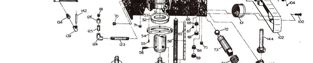
2 OPERATIONS WARNING: DO NOT OVERSTROKE THE RAM. Overstroking will cause premature seal failure. Models 6-225, 6-425, 6-250, and have a 10-inch stroke. Models and have a 16-inch stroke. The press has been completely tested at the factory and after setting up according to instructions above, the press is ready for operation. However, it is necessary for the operator to acquaint themselves with the controls. 1. Three screws (item 109) are used to lock the workhead in the desired position along head channels. 2. The handcrank (item 19) is provided to raise or lower the table channels to the proper work height. When desired height is obtained insert the table pins. Models 6-225, 6-425, and use 2 pins on each side (4 total) and Models 6-275, 6-475, and use 3 pins on each side (6 total). NOTE: Be sure ALL table pins are in place an in as far as they can go before pressure is applied. Be sure to slack off on the cable before pressure is applied. (Refer to point 5 under SETTING UPS THE PRESS FOR OPERATION) 3. The handle on the left side of the control block (item 76) opens and closes the ball valve, which releases pressure on the ram. This valve should be kept firmly closed and opened only when it is desired to return the ram to its up position. 4. The two table plates and two V-blocks are used for supporting the work in process. 5. The control knob (item 103) on the right side of the panel regulates the speed of ram travel. The knob will return to the off position when released. 6. The relief valve (item 90) has been set at factory to open at maximum tonnage of press. The valve can be adjusted by removing hex nut located on top of the valve block at the right front of reservoir and turning the adjusting screw to the left for a lower setting. WARNING: Never exceed rated tonnage of press. MAINTENANCE CAUTION: When disconnecting any parts of this machine be extremely careful that all parts are clean to prevent entrance of dirt in the hydraulic system. 1. If press loses Pressure: a. Check all tubing joints for leaks and tighten the tube nuts. b. Leakage past release valve (Item 72). Drain the reservoir, and remove packing nut (Item75), valve rod (Item 73), and ball valve (Item 72). Clean out valve seat and reseat ball valve using brass rod as a drift striking sharply with a hammer. Reassemble valve rod, packing and packing nut. Refill reservoir with appropriate oil amount. c. Leakage past eductor inlet check ball (Item 69). Drain reservoir, remove large pipe plug (Item 71), valve seat (Item 70), and check ball (Item 69). Clean and inspect seat. Reseat ball on seat or replace seat with a new one if necessary. Reassemble with ball above the seat tightening plugs securely. d. Worn cup leather (Serial No < ) or T-ring seal (Serial No > ). If none of the previous conditions seem to have been the cause of the trouble, the cup leather or T-ring seal may be worn out or damaged. To inspect this it is necessary to drain the oil and remove the workhead from the press frame. Remove tube assembly (Item 144). Set 2 4x4 blocks on the table then raise table channels with the block up to the bottom of the reservoir applying pressure to the reservoir. Remove roller brackets from the reservoir and lower workhead using the table. WARNING: Be sure that stroke indicator rod support (item 61) is installed in the side of the piston. If not, Insert ½ -13 stud or capscrew in tapped hole in piston. This will hold the piston down under spring pressure. Next remove nuts from cylinder flange and lift 2
3 cylinder off piston. The piston leather or T-ring seal can now be inspected and replaced if necessary. Press may be reassembled in reverse order being careful not to damage the lip of the leather cup or T-ring seal as it enters the cylinder. 2. If press will not develop rated tonnage. a. Dirt under valve balls. Refer to MAINTENANCE 1 c above. b. Worn cup leather. Refer to MAINTENANCE 1 d above. c. Relief valve not set properly. This valve is located on the top side near the right end of the control block at the front of the reservoir. The valve is set at the factory to bypass oil from the pump back to the reservoir when the press reaches its rated capacity. The load on the spring (Item 91), which governs the pressure at which the valve will bypass oil, is adjusted by turning the screw (Item 90) in to increase pressure or out to decrease pressure. Replace seal (Item 89) and cap nut (Item 88). NOTE: We advise that the relief valve not be tampered with after it is once set at the capacity of the press. 3. If nothing happens when press is operated. a. Release valve open. Be sure to have release valve firmly closed when using press. b. If the ram will come down only a fraction of its rated stroke, check the oil level in the reservoir with the ram at the top of its stroke. It should be visible in the sight window at the side of the reservoir. 4. If press is operating slow. a. Check air supply line for restrictions to determine if air motors are getting ample supply of air. b. Release valve not closed properly. Release valve must be firmly closed when using the press. c. Wrong hydraulic fluid. After considerable research and tests made with the cooperation of the pump manufacturer, we recommend Mobil DTE 24 oil or equivalent. 5. If Oil is coming out of the air vent. Drain out the spring chamber by removing the 1/8 pipe plug, which is put in the hub or boss that contains the oil seal where the ram extends out of the reservoir. Once oil is drained, run the press up to full tonnage with pipe plug still out. Excessive oil is a sign that the head seal has been damaged. Refer to Maintenance section 1 item d to replace seal. Replace pipe plug. 6. Excessive leakage around the ram. Drain out the spring chamber as instructed in Maintenance section 5. A small amount of oil in this chamber facilitates lubricating the bushing the ram passes thru and prevents scoring. However, if operation performed on press is spoiled due to slight leakage of oil, remove pipe plug as described in MAINTENANCE 5 and connect tube line to continually drain this chamber. 3


4 WARNING LABELS To the left is the safety Alert symbol. When you see these safety alert symbols on your press, be alert to the potential for personal injury. Follow recommended precautions and safe operating practices. Carefully read all safety messages in these instructions and on your press safety signs. Keep safety labels in good condition. Replace missing or damaged safety labels. This machine is intended to be operated by one person. This person should be conscious of the press ram movement not only for himself but also for persons in the immediate area of the machine. Label Label Label Label Placement View Label Label 7355 Label
5 5
6 6
7 Control Block Exploded View 724 Robbins Road Grand Haven, MI Phone: Fax: Web:
8 Ite m Part Name Model Model Model Model Pulley H Frame Hex head cap screw Name plate x ½ Self tapping screw Table plate V-block Table spacer assembly Table channel Lockwasher Hex nut Table pins Table pins Safety clips Base angle Hex cap screw Lockwasher Square nut Cable Cable clamp Hoist crank assembly Worm shaft A Retaining ring B Retaining ring Worm key Worm Hoist frame Hex cap screw Hex nut Drum shaft Drum key Worm gear Cable drum Complete Table Hoist Assembly (Items 20, 21A, 21B, 22, 23, 24, 27, 28, 29,30) Figure S S S S 1 Figure 2 37 ½ Hex Nut Cylinder Gasket ½ -13 x 1-½ Soc. Hd. Cap Screw (Serial No. < ) Piston Bumper (Serial No. < ) ¼ -20x1 HHCS (Serial No. < ) /8-16x1-¼ HHCS (Serial No. < ) /8-16x1-¾ HHCS (Serial No. < ) ¼ Lockwasher (Serial No. < ) /8 Lockwasher (Serial No. < ) Supporting Ring (Serial No. < ) Leather Cup (Serial No. < ) T-ring Seal (Serial No. > ) Cylinder Piston Assembly (Serial No. < ) Piston Assembly (Serial No. > ) Ram Spring (Small) Spring Spacer Qty
9 50 Ram Spring (Large) Model Model Model Model Ite Part Name m Qty 51 Piston Bushing (Serial No. < ) Wear Ring (Serial No. > ) Oil Seal Oil Seal Gasket Retaining Plate No x ½ Rd. Hd. Screw /16 Set Screw Nose Piece Assembly V-Nose Assembly Stroke Indicator Rod ½ -13 Hex Jam Nut Special Nut ¼ -20 x ¼ Soc. Hd. Set Screw Support Stud No. 2 x 3/16 Drive Screw Scale Reservoir Assembly /8 N.P.T.F. Soc. Hd. Pipe Plug Check Valve Seat ½ N.P.T.F. Soc Hd. Pipe Plug /8 N.P.T.F. Soc Hd. Pipe Plug ¼ N.P.T.F. Soc. Hd. Pipe Plug Ball Valve ¾ Dia Release Valve Rod Valve Rod Packing Packing Nut Valve Handle 2230A 2230A 2230A 2230A 1 77 Handle Washer /8-16 x ¾ Hex Cap Screw Plunger Unit Pivot Pin Air Control Arm Air Control Link Air Control Shaft Pin /16 x ½ Cotter Pin Valve Cap Nut O-ring Relief Valve Adj, Screw Relief Valve Spring Ball Retainer Ball Valve ¼ Dia Relief Valve Seat Check Valve Spring Check Valve Spring Ball Valve ½ Dia No x 2-¾ Machine Screw Gauge Control Pannel
10 103 Control Knob 2250A 2250A 2250A 2250A 1 Model Model Model Model Ite Part Name m Qty 104 ¼ -20 x ½ Soc. Hd. Set Screw ½ Washer /8-11 Hex Nut Rear Roller Bracket ¾ -10 x 3 Set Screw Flanged Roller Bearing Front Roller Bracket Pump Haskel Air /8 Pipe Nipple ¾ x 4 Pipe Nipple ¾ 90 Pipe Elbow ¾ x 2 Pipe Nipple ¾ Pipe Coupling /8 Street Elbow /8 Pipe Nipple Quick Exhaust Restrictor /8 Pipe Nipple ¼ - 1/8 Bushing ¼ 90 Street Elbow ¼ Pipe Coupling Check Valve Tube Fitting Air Vent Tube Tube Tube Elbow Tube Assembly Tube Elbow Tube Assembly Tube Elbow Tube Assembly Cylinder Repair Kit (Items: 39, 45, 52, 53, 72, 74, 89, 93, 97) Haskel Pump Repair Kit ADDED PARTS USED WITH DOUBLE PUMP PRESSES NOT ILLUSTRATED 115 Pump Tube Fitting Tube Tee Tube Tee Tube Assembly Straight Fitting Tube Assembly Straight Fitting Tube Assembly
11 11
INSTRUCTIONS AND PARTS LIST FOR Models 8-025, 8-050, 8-075, and Elec-Draulic II Presses
 INSTRUCTIONS AND PARTS LIST FOR Models 8-025, 8-050, 8-075, and 8-150 Elec-Draulic II Presses SETTING UP THE PRESS FOR OPERATION For shipping convenience some of the parts are not assembled. Assemble these
INSTRUCTIONS AND PARTS LIST FOR MODEL 125H & 150H HAND-OPERATED HYDRAULIC PRESS
 INSTRUCTIONS AND PARTS LIST FOR MODEL 125H & 150H HAND-OPERATED HYDRAULIC PRESS SETTING UP THE PRESS FOR OPERATION For shipping convenience, the gauge, pump handle, hoist crank, screw nose and base angles
INSTRUCTIONS AND PARTS LIST FOR MODEL 25H HAND-OPERATED HYDRAULIC PRESS
 INSTRUCTIONS AND PARTS LIST FOR MODEL 25H HAND-OPERATED HYDRAULIC PRESS SETTING UP THE PRESS FOR OPERATION For shipping convenience, the gauge, pump handle, hoist crank, screw nose and base angles were
INSTRUCTIONS AND PARTS LIST FOR MODEL 70H & 75H HAND-OPERATED HYDRAULIC PRESS
 INSTRUCTIONS AND PARTS LIST FOR MODEL 70H & 75H HAND-OPERATED HYDRAULIC PRESS SETTING UP THE PRESS FOR OPERATION For shipping convenience, the gauge, pump handle, hoist crank, screw nose and base angles
INSTRUCTIONS AND PARTS LIST FOR Model Elec-Draulic I Presses
 INSTRUCTIONS AND PARTS LIST FOR Model 5-200 Elec-Draulic I Presses WARNING LABELS To the left is the safety Alert symbol. When you see these safety alert symbols on your press, be alert to the potential
INSTRUCTIONS AND PARTS LIST FOR Models 5-025, 5-050, 5-075, and Elec-Draulic I Presses
 INSTRUCTIONS AND PARTS LIST FOR Models 5-025, 5-050, 5-075, and 5-150 Elec-Draulic I Presses WARNING LABELS To the left is the safety Alert symbol. When you see these safety alert symbols on your press,
Model 5-025, 5-050, &
 Model 5-025, 5-050, 5-075 & 5-150 7 Model 5-025, 5-050, 5-075 & 5-150 8 Eductor Block Exploded View Model 5-025, 5-050, 5-075 & 5-150 9 Figure 1 Item Part Name Model Model Model Model 5-025 5-050 5-075
Parts list. See Frame parts list Page 12. See hydraulic pump. exploded view. Page 14. See work head. exploded view. Page 7
 Parts list See Frame parts list Page 12 See hydraulic pump exploded view Page 14 See work head exploded view Page 7 See electrical parts list Page 18 See hoist parts list Page 11 See Frame parts list Page
INSTRUCTIONS AND PARTS LIST FOR MODEL FORCE 10DA and FORCE 25DA (Double Acting, Electrically-Operated Hydraulic Press)
") INSTRUCTIONS AND PARTS LIST FOR MODEL FORCE 10DA and FORCE 25DA (Double Acting, Electrically-Operated Hydraulic Press) Operation 1. Plug power cord into a 115-volt A.C. single phase 60-cycle grounded,
INSTRUCTIONS AND PARTS LIST FOR MODEL FORCE 10DA and FORCE 25DA (Double Acting, Electrically-Operated Hydraulic Press) Operation 1. Plug power cord into a 115-volt A.C. single phase 60-cycle grounded,
INSTRUCTIONS AND PARTS LIST FOR MODEL FORCE 10DA and FORCE 25DA (Double Acting, Electrically-Operated Hydraulic Press)
") INSTRUCTIONS AND PARTS LIST FOR MODEL FORCE 10DA and FORCE 25DA (Double Acting, Electrically-Operated Hydraulic Press) Thank you for buying Dake!!!! We hope you enjoy many years of using your new Dake
INSTRUCTIONS AND PARTS LIST FOR MODEL FORCE 10DA and FORCE 25DA (Double Acting, Electrically-Operated Hydraulic Press) Thank you for buying Dake!!!! We hope you enjoy many years of using your new Dake
FORCE 50 DA HYDRAULIC PRESS INSTRUCTIONS AND PARTS LIST
 FORCE 50 DA HYDRAULIC PRESS INSTRUCTIONS AND PARTS LIST Ordering information Please order all parts by part number and name; also mention model number as shown on plate attached to the frame of the press.
Property of American Airlines
 Date: September, 00 MALABAR INTERNATIONAL AIRCRAFT MAINTENANCE & SUPPORT EQUIPMENT READ AND SAVE THIS INSTRUCTION MANUAL OWNER'S MANUAL FOR MALABAR MODEL A SINGLE STAGE VARIABLE HEIGHT HYDRO - MECHANICAL
High Lift Transmission Jack
 655 Eisenhower Drive Owatonna, MN 55060 USA Phone: (507) 455-7000 Tech. Serv.: (800) 533-6127 Fax: (800) 955-8329 Order Entry: (800) 533-6127 Fax: (800) 283-8665 International Sales: (507) 455-7223 Fax:
Shop Press. Maximum Capacity: 25 Tons and 55 Tons SAFETY PRECAUTIONS
 Operating Instructions for: Form No. 102481 1826 1845 1846A 1847 1872 1872-220v 211200 576780 60361 61275 D01008AA D01009AA WARNING: To prevent personal injury; Shop Press Maximum Capacity: 25 Tons and
LB601B PARTS LIST COMPRESSORS CB-5E /06. Bulletins Needed For Complete Parts List. Gasket Set, Repair Kits and Special Tools
 COMPRESSORS CB-5E-051 2011/06 LB601B PARTS LIST Serial # ID# Gasket Set, Repair Kits and Special Tools Gasket Set Buna-N & Aluminum 794099 Top End Repair Kit 794237 Includes Piston Rings & Expanders, Packing
SERVICE INSTRUCTIONS D TON
 1120 SOUTH CRYSTAL AVE * BENTON HARBOR MI PH: 269-925-7777 FAX: 269-925-6656 SERVICE INSTRUCTIONS D-51223 4 TON TO ASSEMBLE: 1. Check the handle set screw for tightness. CUSTOMER PRE-USE INSTRUCTIONS THE
Under Axle Jack Max. Capacity: 25 Tons
 SPX Corporation 655 Eisenhower Drive Owatonna, MN 55060-0995 USA Phone: (507) 455-7000 Tech. Serv.: (800) 533-6127 Fax: (800) 955-8329 Order Entry: (800) 533-6127 Fax: (800) 283-8665 International Sales:
Service Jacks. Operating Instructions & Parts Manual. Model Number. Capacity 4 Ton 4 Ton Air/ Manual 10 Ton 10 Ton Air/ Manual HW93657/ HW93660
 Service Jacks Operating Instructions & Parts Manual Model Number HW93657 HW93667 HW93660 HW93662 Capacity 4 Ton 4 Ton Air/ Manual 10 Ton 10 Ton Air/ Manual Made in North America HW93657/ HW93660 HW93667/
Property of American Airlines
 Date: November 22, 1999 MALABAR INTERNATIONAL AIRCRAFT MAINTENANCE & SUPPORT EQUIPMENT READ AND SAVE THIS INSTRUCTION MANUAL OWNER'S MANUAL FOR MALABAR MODEL 60P10 TWO STAGE HYDRAULIC AVIATION FLOATING
Binks MODELS & AGITATOR DRIVE UNITS
 Binks MODELS 31-393 & 31-394 AGITATOR DRIVE UNITS for Agitator Equipped Drum MODEL 31-393 Includes the following items: 1, 2, and 3. 1 MODEL 31-394 shown. 17 4 3 2 12 13 14 15 2 3 8 5 9 11 8 10 6 7 17
Craftsman Snow Thrower Model PARTS LIST
 Craftsman Snow Thrower Model 24.881900 PARTS LIST 11 13 3 2 24 9 1 18 4 2 1 20 23 1 14 1 9 2 4 4 4 3 28 8 3 4 3 39 0 3 43 38 2 48 2 42 1 41 40 49 4 44 31 4 31 21 29 34 9 19 10 32 22 2 Craftsman Snow Thrower
Gear Products Inc N. 161st E. Ave. Tulsa, OK Phone (918) Fax (918)
 Fax (918)") SERVICE MANUAL Disassembly & Assembly Procedures Worm Gear Swing Drive 003 Series Gear Products Inc. 1111 N. 161st E. Ave. Tulsa, OK 74116 Phone (918) 234-3044 Fax (918) 234-3455 Worm Gear Swing Drive
SERVICE MANUAL Disassembly & Assembly Procedures Worm Gear Swing Drive 003 Series Gear Products Inc. 1111 N. 161st E. Ave. Tulsa, OK 74116 Phone (918) 234-3044 Fax (918) 234-3455 Worm Gear Swing Drive
ANDERSON GREENWOOD SERIES 500 PILOT OPERATED SAFETY RELIEF VALVES INSTALLATION AND MAINTENANCE INSTRUCTIONS
 Before installation these instructions must be fully read and understood TABLE OF CONTENTS 1. General valve description and start-up... 1 2. Main valve maintenance... 1 3. Pilot maintenance... 5 4. Pilot
Trick-Tools 75 Truman Road Pella, IA Phone:1-877-VAN-SANT
 Distributed by: Trick-Tools 75 Truman Road Pella, IA 50219 Phone:1-877-VAN-SANT E-mail: sales@trick-tools.com Here at Trick Tools we believe that our customers deserve the best value in their tool and
High Lift Transmission Jack
 SPX Corporation 655 Eisenhower Drive Owatonna, MN 55060-0995 USA Phone: (507) 455-7000 Tech. Serv.: (800) 533-6127 Fax: (800) 955-8329 Order Entry: (507) 455-1480 Fax: (800) 283-8665 International Sales:
RC-200EX / RC-150EX Rim Clamp Tire Changer
 RC-200EX / RC-150EX Rim Clamp Tire Changer For servicing motorcycle and ATV tire/wheel assemblies as well as automotive and most light truck tire/wheel assemblies (holds 6 to 8-inch wheels for manual tire
MODEL HD-BTC. Installation, Operation & Repair Parts Information REV041416
 MODEL HD-BTC Installation, Operation & Repair Parts Information REV041416 TABLE OF CONTENTS SAFETY INSTRUCTIONS 1 DEFINITIONS 1 SPECIFICATIONS 2 INSTALLATION INSTRUCTIONS 2 OPERATING INSTRUCTIONS 2 MAINTENANCE
PARTS LIST. Craftsman 5.5 HP Snow Thrower Model
 24 Craftsman 5.5 HP Snow Thrower Model 24.88355 1. 31-2635 Snow Removal Tool Mount 2. 684-0405 Impeller Assembly, 12 Dia. 3. 10-034 Hex Screw, 3/8-16, 1.5, Gr5 4. 10-0451 Bolt, Carriage, 5/16-18,.50 Gr1
INSTALLATION MANUAL. MB-180, MB-210 and MB-210L Motor Brake INSTALLATION. Force Control Industries, Inc. DESCRIPTION OPERATION
 MB-180, MB-210 and MB-210L Motor Brake INSTALLATION MANUAL 512-180-001-00 DESCRIPTION Posistop Motor Brakes are multiple surface, spring activated, pneumatic release braking devices that effectively dissipate
MOREHOUSE INSTRUMENT COMPANY, INC. 60,000 LBS CAPACITY AIRCRAFT PART NUMBER SCALE S FORCE CALIBRATION PRESS PART NO.
 INDEX 1. GENERAL SPECIFICATION AND DRAWING 804000-03... 2 2. ASSEMBLY INSTRUCTIONS... 5 3. OPERATING INSTRUCTIONS... 6 4. MAINTENANCE INSTRUCTIONS... 7 5. CERTIFICATE OF CAPACITY LOAD TEST AND OVERLOAD...
LB361B PARTS LIST COMPRESSORS CB-5E /06. Bulletins Needed For Complete Parts List. Gasket Set, Repair Kits and Special Tools
 COMPRESSORS CB-5E-031 2011/06 LB361B PARTS LIST Serial # ID# Gasket Set, Repair Kits and Special Tools Gasket Set Buna-N & Aluminum 793099 Top End Repair Kit 793229 Includes Piston Rings & Expanders, Packing
WEAVER JACK CORP. MASTER PARTS PRICE & IDENTIFICATION LIST. (517) Fax (517) MINIMUM BILLING $20.00
 Fax (517) MINIMUM BILLING $20.00") EFFECTIVE JULY 1, 2014 WEAVER JACK CORP. MASTER PARTS PRICE & IDENTIFICATION LIST (517) 263-6500 Fax (517) 263-2810 MINIMUM BILLING $20.00 THIS PRICE LIST SUPERSEDES ALL PREVIOUS PARTS PRICE LISTS (Prices
EFFECTIVE JULY 1, 2014 WEAVER JACK CORP. MASTER PARTS PRICE & IDENTIFICATION LIST (517) 263-6500 Fax (517) 263-2810 MINIMUM BILLING $20.00 THIS PRICE LIST SUPERSEDES ALL PREVIOUS PARTS PRICE LISTS (Prices
Disassembly and Assembly
 SENR9973-01 September 2007 Disassembly and Assembly 400C Industrial Engine HB (Engine) HD (Engine) HH (Engine) HL (Engine) HM (Engine) HN (Engine) HP (Engine) HR (Engine) Important Safety Information Most
Instruction Manual. Maximum Operating Pressure 700 bar
 Remote Hydraulic Cutter Model HC-120R Maximum Operating Pressure 700 bar ABSOLUTE EQUIPMENT PTY LTD 2/186 Granite Street, GEEBUNG QLD 4034 Australia sales@absoluteequipment.com.au Phone: +61 7 3865 4006
4050A. Tire Changer. Parts Identification. For servicing single piece automotive and most light truck tire/wheel assemblies
 4050A Tire Changer For servicing single piece automotive and most light truck tire/wheel assemblies Parts Identification READ these instructions before placing unit in service KEEP these and other materials
PARTS LIST FOR HDB H6G HDB K7G
 PARTS LIST FOR HDB-3004-0H6G HDB-3004-0K7G ENGINE OIL GRADE: HONDA: KOHLER: SAE10W-30 SAE20W-40 FUEL NOZZLE: BTU INPUT: 343,000 2.25 80 B Delavan PUMP OIL GRADE: PUMP OIL CAPACITY: SAE 20 or 30 Non-Detergent
Service Handbook. High-Pressure Washer Pump
 Pump 629 9/28/01 3:22 PM Page 1 Service Handbook High-Pressure Washer Pump 3.532-629.0 10.00 Pump 629 9/28/01 3:22 PM Page 2 Pump 629 9/28/01 3:22 PM Page 3 TROUBLESHOOTING OVERVIEW How to Use This Manual
MK-5000G exploded VieW
 Frame accessories 38 cutting head Pump Assembly 39 connecting linkage foot pedal linkage 40 curtain blade guard 41 ENGINE Assembly 42 PARTS LIST A Frames - - A1 Frame, MK-5000 Main 1 155541 B Pivot Bracket
Hydraulic Telescopic Transmission Jack
 Hydraulic Telescopic Transmission Jack Operating Instructions & Parts Manual Model Number HW93720 Capacity 1/2 Ton Made in the U.S.A.! This is the safety alert symbol. It is used to alert you to potential
CENTRO-MATIC PUMP, MODELS 84050, & 85460
 CENTRO-MATIC DEC - 2006 Section - C8 - C8 Page - 142S Table of Contents Page Safety...2 Specifications...2 Description...2 Pump Operation...2 Installing the Pump...2 Optional Devices......3 Puffing Pump
TECHNICAL SERVICE MANUAL
 Electronic copies of the most current TSM issue can be found on the Viking Pump website at www.vikingpump.com TECHNICAL SERVICE MANUAL industrial heavy duty motor speed pumps SERIES 4076 AND 4176 SIZES
TABLE OF CONTENTS VC 620 / 628 / 5520 / 6620 / 6628 MANUAL TABLE OF CONTENTS F VC VC 6628 PAGE DESCRIPTION REF. NO.
 TABLE OF CONTENTS VC 620 / 628 / 5520 / 6620 / 6628 MANUAL PAGE DESCRIPTION REF. NO. 1 READ THIS FIRST... 416733 2 IMPORTANT WARNING... 416086 3 WARNING AND CAUTION DECALS... 416128 4 VC 620 CAPACITIES...
HD603C PARTS LIST. Gasket Set Buna-N & Iron FKM & Iron PTFE & Iron Neoprene & Iron Ethylene Propylene & Iron
 COMPRESSORS CB-9E-152 2007/01 HD603C PARTS LIST Serial # ID# Gasket Sets and Special Tools Gasket Set Buna-N & Iron 794594 FKM & Iron 794592 PTFE & Iron 794593 Neoprene & Iron 794590 Ethylene Propylene
CONTENTS. VIKING PUMP, INC. A Unit of IDEX Corporation Cedar Falls, IA USA SECTION TSM 710.1
 TECHNICAL SERVICE MANUAL industrial heavy duty motor speed pumps SERIES 4076 AND 4176 SIZES hle, ate and ale SECTION TSM 710.1 PAGE 1 of 8 ISSUE B CONTENTS Introduction....................... 1 Safety
MODEL NO & UP SAFETY AND INSTRUCTION DECALS
 FORM NO. 95-2194 REV. B MODEL NO. 41105-90001 & UP PARTS CATALOG MULTI PRO 1100 VEHICLE SAFETY AND INSTRUCTION DECALS The following safety and instruction decals are installed on the vehicle. If any become
Fast-Flo Pump INSTRUCTIONS-PARTS LIST. Table of Contents 1:1 RATIO
 INSTRUCTIONS-PARTS LIST INSTRUCTIONS This manual contains important warnings and information. READ AND KEEP FOR REFERENCE. First choice when quality counts. 07 7 Rev. Z Supersedes W Includes Rev. Y changes
INSTALLATION MANUAL. MB-250, MB-280 and MB-320 Motor Brake INSTALLATION. Force Control Industries, Inc. DESCRIPTION OPERATION
 MB-250, MB-280 and MB-320 Motor Brake INSTALLATION MANUAL 512-250-001-00 DESCRIPTION Posistop Motor Brakes are multiple surface, spring activated, pneumatic release braking devices that effectively dissipate
KJ Motor/Pump Assembly. Jetter. Printed in U.S.A. Ridge Tool Company/Elyria, Ohio, U.S.A.
 KJ-000 Motor/Pump Assembly NOTE: Order parts by Number Only. 0 0 0 Gasoline Engine, Hp Manual Start 0 Gasoline Engine, Hp Electric Start Decal, Warning 0 Decal, Fuel Warning Decal, Model. KJ-000 Key, /
OPERATOR S MANUAL Model 60010
 OPERATOR S MANUAL Model 60010 10- TON SNAP LOCK PORTA POWER SET W/ WHEELED CASE PROFESSIONAL HYDRAULIC JACKS 1531 W. Mohawk Drive Phone 715-453-9602 Customer Service 800-995-2250 Tomahawk, WI 54487 Fax
Telescopic Transmission Jack
 Telescopic Transmission Jack Operating Instructions & Parts Manual Model Number HW93720 Capacity 1/2 Ton Made in the USA SAVE THESE INSTRUCTIONS For your safety, read, understand, and follow the information
Maintenance Manual Reduced Pressure Assembly Models 860 & 880V 2 1 /2" 10"
 IOM-F-860_880V INSTALLATION, OPERATION, MAINTENANCE Maintenance Manual Reduced Pressure Assembly Models 860 & 880V 2 1 /2" 10" 860 880V Standard Configuration 880V Vertical Configuration INDEX Vandalism..............................................
1984 Dodge W250 PICKUP
 1984 Dodge W250 PICKUP Submodel: Engine Type: V8 Liters: 5.2 Fuel Delivery: CARB Fuel: GAS Dana 44 MODELS THROUGH 1984 2. Raise and safely support the vehicle, then remove the wheel hub and bearings as
Ramsey Winch Company OWNER'S MANUAL MODEL H-800 SERIES DOW-LOK EQUIPPED INDUSTRIAL LOW-MOUNT WINCH
 Ramsey Winch Company OWNER'S MANUAL MODEL H-800 SERIES DOW-LOK EQUIPPED INDUSTRIAL LOW-MOUNT WINCH Rated Line Pull (lbs.) 20,000 (Kg.) 9,060 Gear Reduction 40:1 Worm RPM.. 460 @ 30 GPM Weight (without
Super 1050 Chain Saw UT Page 1 of 16 Carburetor Chamber
 Super 1050 Chain Saw UT-10139 Page 1 of 16 Carburetor Chamber Super 1050 Chain Saw UT-10139 Page 2 of 16 Carburetor Chamber 1 58319A 1 RING- Retaining 2 592301 1 COVER- Air filter 3 A70326 1 NUT- Cover
HD612C PARTS LIST. Gasket Set Buna-N & Iron FKM & Iron PTFE & Iron Neoprene & Iron Ethylene Propylene & Iron
 COMPRESSORS CB-9E-192 2007/01 HD612C PARTS LIST Serial # ID# Gasket Sets and Special Tools Gasket Set Buna-N & Iron 794699 FKM & Iron 794697 PTFE & Iron 794698 Neoprene & Iron 794696 Ethylene Propylene
COMPRESSORS 09/97 CB-5C-050. Suggested Spare Parts for LB601 and LB601A Compressors: Qty./ Unit
 09/97 CB-5C-050 Suggested Spare Parts for LB601 and LB601A Compressors: Part # Description Qty./ Unit Comm. Qty. 794099 Gasket Set - Buna-N, Aluminum T 1 1 1 794259 Suction Valve Sub-Assembly T 2 2 794279
HOT WATER PRESSURE WASHER
 FRAME ASSEMBLY HW353HAD 8 5 6 7 9 20 2 22 23 24 25 2 M:\Drawings\PRIVATE LABEL\BE PRESSURE SUPPLY\HSP LARGE\HSP-3500 ASSEMBLY.iam 5 4 3 2 29 28 0 9 8 7 6 ITEM DESCRIPTION Part # QTY Hose Reel Mounting
Air Assist Bottle Jack Max. Capacity: 12 Tons (4313C) & 20 Tons (4321C) Operating Range: psi
 & 20 Tons (4321C) Operating Range: psi") Form No. 545742 Parts List and Operating Instructions for: 4313C 4321C Air Assist Bottle Jack Max. Capacity: 12 Tons (4313C) & 20 Tons (4321C) Operating Range: 40 150 psi 45 44 43 42 41 40 39 22 1 37 28
Form No. 545742 Parts List and Operating Instructions for: 4313C 4321C Air Assist Bottle Jack Max. Capacity: 12 Tons (4313C) & 20 Tons (4321C) Operating Range: 40 150 psi 45 44 43 42 41 40 39 22 1 37 28
CRYSTEEL S HOIST. this manual must be included with the vehicle after completing the installation.
 Website: www.tbei.com E-mail: sales@tbei.com CRYSTEEL S STINGRAY HOIST this manual must be included with the vehicle after completing the installation. Web Site E-Mail Phone (507) 726-2728 www.crysteel.com
RITE WAY MFG. CO. LTD. P.O.
 CO. LTD. P.O. Box 328 Imperial, Saskatchewan Canada, S0G 2J0 Ph: (306) 963-280 Fax: (306) 963-2660 Web Site: www.ritewaymfg.com E-mail: info@ritewaymfg.com Table of Contents SPECIFICATIONS... WARNING...2
Tech. Services: (800) Fax: (800) Order Entry: (800) Fax: (800) MODEL C ELECTRIC HYDRAULIC PUMP
 Fax: (800) Order Entry: (800) Fax: (800) MODEL C ELECTRIC HYDRAULIC PUMP") SPX Corporation 5885 11th Street Rockford, IL 61109-3699 USA Internet Address: http://www.powerteam.com Tech. Services: (800) 477-8326 Fax: (800) 765-8326 Order Entry: (800) 541-1418 Fax: (800) 288-7031
SPX Corporation 5885 11th Street Rockford, IL 61109-3699 USA Internet Address: http://www.powerteam.com Tech. Services: (800) 477-8326 Fax: (800) 765-8326 Order Entry: (800) 541-1418 Fax: (800) 288-7031
Cut Away Tire Bead Breaker Model 10101
 Cut Away Tire Bead Breaker Model 10101 DESCRIPTION PART NUMBER Hex Hd Cap Screw 7/16-14 x 2 12901 Handle Strap Pivot 36949 Piston 350455 Wiper 16720 U-Cup 16721 Spring Anchor 201360 Spring EXT OD.830ID.533R48L1.9300T
KJ Motor/Pump Assembly. Jetter. Printed in U.S.A. Ridge Tool Company/Elyria, Ohio, U.S.A.
 KJ-000 Motor/Pump Assembly NOTE: Order parts by Number Only. 0 0 0 Gasoline Engine, Hp Manual Start 0 Gasoline Engine, Hp Electric Start Decal, Warning 0 Decal, Fuel Warning Decal, Model. KJ-000 Key, /
Vickers. Overhaul Manual. Vane Pumps. Small and Large Series Combination Pumps VC(K)(S)-**-(*)*D*-6(1) VC(K)(S)-**-(*)-*-*D*-5(1)
(S)-**-(*)*D*-6(1) VC(K)(S)-**-(*)-*-*D*-5(1)") Overhaul Manual Vickers Vane Pumps Small and Large Series Combination Pumps VC(K)(S)-**-(*)*D*-6(1) VC(K)(S)-**-(*)-*-*D*-5(1) Revised 12/1/86 I-3150-S Table of Contents Section I. Introduction................................................................................
Overhaul Manual Vickers Vane Pumps Small and Large Series Combination Pumps VC(K)(S)-**-(*)*D*-6(1) VC(K)(S)-**-(*)-*-*D*-5(1) Revised 12/1/86 I-3150-S Table of Contents Section I. Introduction................................................................................
1988 Chevrolet Pickup V SUSPENSION - FRONT (4WD)' 'Front Suspension - "V" Series 1988 SUSPENSION - FRONT (4WD) Front Suspension - "V" Series
' 'Front Suspension - V Series 1988 SUSPENSION - FRONT (4WD) Front Suspension - V Series") 1988 SUSPENSION - FRONT (4WD) Front Suspension - "V" Series DESCRIPTION NOTE: Vehicle serial numbers used in this article has been abbreviated for common reference to Chevrolet and GMC models. Chevrolet
1988 SUSPENSION - FRONT (4WD) Front Suspension - "V" Series DESCRIPTION NOTE: Vehicle serial numbers used in this article has been abbreviated for common reference to Chevrolet and GMC models. Chevrolet
PARTS LIST AND SERVICE MANUAL
 CD40 SERIES PTO PARTS LIST AND SERVICE MANUAL HEAVY DUTY, CONSTANT DRIVE PTO FOR THE ALLISON WORLD TRANSMISSION CD40 SERIES CONSTANT DRIVE PTO EXPLODED VIEW CD40 COVER DETAIL (Backside) PTO ASSEMBLY ARRANGEMENTS
Eclipser 2500/2800 OPERATING MANUAL. and Continuous Coil (CC) Clipping System. ENCORE (EA) ECLIPSER 2500 and 2800 SERIES
 Clipping System. ENCORE (EA) ECLIPSER 2500 and 2800 SERIES") Eclipser 2500/2800 and Continuous Coil (CC) Clipping System Encore Eclipser 2500 Series (Green) Hartco Eclipser 2500 (Black) not shown OPERATING MANUAL ENCORE (EA) ECLIPSER 2500 and 2800 SERIES Pneumatic
Eclipser 2500/2800 and Continuous Coil (CC) Clipping System Encore Eclipser 2500 Series (Green) Hartco Eclipser 2500 (Black) not shown OPERATING MANUAL ENCORE (EA) ECLIPSER 2500 and 2800 SERIES Pneumatic
PACKING, HANDLING, TRANSPORTING AND STORING MOTORS
 PACKING, HANDLING, TRANSPORTING AND STORING MOTORS Make sure that the shaft of the motor is not loaded in any way and is protected from knocks. Axial loads or shocks may easily damage the bearings inside
Post Driver Attachment
 Attachment (Shown with Optional Power Cell Rotator) Models - 600, 850 Safety Instructions This safety alert symbol indicates important safety messages in this manual. When you see this symbol, carefully
Operating Instructions & Parts Manual. Capacity 4 Ton. 10 Ton 10 Ton
 Service Jacks Operating Instructions & Parts Manual Model Number HW93657 HW93667 (Air/Manual) HW93660 HW93662 (Air/Manual) Capacity 4 Ton 4 Ton 10 Ton 10 Ton Made in the U.S.A. Model No. HW93657 & HW93660
PARTS LIST FOR GC MAH and GC MGH (GRAINGER ITEM #6CGP0 AND #6CGP1) COLD WATER PRESSURE WASHER (AFTER SERIAL # )
 COLD WATER PRESSURE WASHER (AFTER SERIAL # )") PARTS LIST FOR GC-5004-3MAH and GC-6004-3MGH (GRAINGER ITEM #6CGP0 AND #6CGP1) COLD WATER PRESSURE WASHER (AFTER SERIAL #10738662) MANUFACTURED FOR W.W. GRAINGER INC. FOR REPLACEMENT PARTS CALL GRAINGER
PARTS LIST FOR GC-5004-3MAH and GC-6004-3MGH (GRAINGER ITEM #6CGP0 AND #6CGP1) COLD WATER PRESSURE WASHER (AFTER SERIAL #10738662) MANUFACTURED FOR W.W. GRAINGER INC. FOR REPLACEMENT PARTS CALL GRAINGER
Hydrostatic Zero-Turn Commercial Riding Mower
 Hydrostatic Zero-Turn Commercial Riding Mower Professional Turf Equipment 0" Fabricated Deck ILLUSTRATED PARTS LIST TABLE OF CONTENTS Frame Assembly.................................. 3 0" Fabricated Cutter
HDC SERIES (AFTER SERIAL # )
") PARTS LIST FOR HDC SERIES (AFTER SERIAL #15019140) ENGINE OIL GRADE: HONDA: KOLHER: VANGUARD: PUMP OIL GRADE: PUMP OIL CAPACITY: FUEL NOZZLE: HDC-3005/3505: HDC-4004: Above 50 F = SAE30 SAE10W-30 Above
PARTS LIST FOR HDC SERIES (AFTER SERIAL #15019140) ENGINE OIL GRADE: HONDA: KOLHER: VANGUARD: PUMP OIL GRADE: PUMP OIL CAPACITY: FUEL NOZZLE: HDC-3005/3505: HDC-4004: Above 50 F = SAE30 SAE10W-30 Above
HORSE III 8HP ROTO TILLER (S/N ) Page 1 of 25 Bolo Tine Assemblies
 Page 1 of 25 Bolo Tine Assemblies") HORSE III 8HP ROTO TILLER (S/N 640000-855638) Page 1 of 25 Bolo Tine Assemblies HORSE III 8HP ROTO TILLER (S/N 640000-855638) Page 2 of 25 Bolo Tine Assemblies 1 GW-2415 2 S/F TINE HOLDER- welded steel.
HORSE III 8HP ROTO TILLER (S/N 640000-855638) Page 1 of 25 Bolo Tine Assemblies HORSE III 8HP ROTO TILLER (S/N 640000-855638) Page 2 of 25 Bolo Tine Assemblies 1 GW-2415 2 S/F TINE HOLDER- welded steel.
60-TON-S/D HYDRAULIC
 SPX Corporation 88 th Street Rockford, IL 09-99 US Internet ddress: http://www.powerteam.com Tech. Services: (800) 77-8 Fax: (800) 7-8 Order Entry: (800) -8 Fax: (800) 88-70 Form No. 0000 Operating Instructions
MK-101 w/jcs Stand TILE SAW OWNER S MANUAL & OPERATING INSTRUCTIONS SERIAL NUMBER:
 MK-0 w/jcs Stand TILE SAW OWNER S MANUAL & OPERATING INSTRUCTIONS CAUTION: Read all safety and operating instructions before using this equipment Enter the Serial Number of your new saw in the space below.
Removal and Installation of Fuel Injection Pumps
 Page 16 of 126 worn considerably. Fig. C shows how the flat end of a new plunger makes poor contact with a worn lifter, resulting in rapid wear to both parts. An injection pump can have a good fuel flow
DeZURIK " BAW AWWA BUTTERFLY VALVES WITH EPOXY-RETAINED SEAT
 DeZURIK 20 144" BAW AWWA BUTTERFLY VALVES WITH EPOXY-RETAINED SEAT Instruction D10373 April 2017 Instructions These instructions provide information about the 20 (250 F2 model only) and the 24-144 BAW
RUFNEK 80 DESIGN SERIES 001 SERVICE MANUAL INTRODUCTION AND THEORY OF OPERATION...2 ASSEMBLY NUMBER EXPLANATION...2 WINCH MODEL CODES...
 RUFNEK 80 DESIGN SERIES 001 SERVICE MANUAL INTRODUCTION AND THEORY OF OPERATION...2 ASSEMBLY NUMBER EXPLANATION...2 WINCH MODEL CODES...2!WARNING!...3 MAINTENANCE...4 GENERAL DISASSEMBLY...5 A. MOTOR DISASSEMBLY...5
Product Parts Information
 Product s Information Model FA5i (Dwg MHP2669) Save These Instructions Form MHD56287 Edition 4 December 2010 71444269 2010 Ingersoll-Rand Company Only allow Ingersoll Rand trained technicians to perform
Valtek Auxiliary Handwheels and Limit Stops
 Valtek Auxiliary s and Limit Stops Table of Contents Page 1 General information 2 Installation 2 Side-mounted handwheels, size 25 and 50 (linear actuators) 3 Side-mounted handwheels, size 100 and 200 (linear
OPERATING INSTRUCTIONS & SERVICE MANUAL BLUE MAX II HYDROSTATIC TEST PUMP
 PAGE 1 OF 10 OPERATING INSTRUCTIONS & SERVICE MANUAL BLUE MAX II HYDROSTATIC TEST PUMP EFFICIENT, EASY OPERATION Air operated pump Wide range of pressures and volumes Easy to operate controls Output pressure
STX-26 Stump Grinder
 Form No. 3365-311 Rev B STX-26 Stump Grinder Model No. 23210 Serial No. 310000001 and Up Model No. 23210G Serial No. 310000001 and Up Register at www.toro.com. Original Instructions (EN) *3365-311* B Ordering
Medium Pressure Diaphragm Pumps
 Medium Pressure Diaphragm Pumps Installation, Operation, Repair, and Parts Manual Form L-1382 4/06 Description Hypro medium pressure diaphragm pumps are recommended for spraying herbicides, pesticides,
ELECTRICAL COMPONENTS
 ELECTRICAL COMPONENTS Part No. Part Name Qty Part No. Part Name Qty 301461 Electrical box 1 716558 Coolant on/off button 1 301462 Connector 24 volt 1 716540 Start button (green) 1 301795 Overload 1 716539
Liftgate Terminology
 SL-20 Series SL-20 Series Click the appropriate link below for the major component of the liftgate for which you are trying to find the correct part. If you are unsure of the name of the part in Waltco
Owner's Manual. Model: ( ) (150 Gallon, 5.5 HP Skid Sprayer) Technical Specifications. General Information. Warranty/Parts/Service
 (150 Gallon, 5.5 HP Skid Sprayer) Technical Specifications. General Information. Warranty/Parts/Service") Owner's Manual Model: -0 (00) (0 Gallon,. HP Skid Sprayer) Technical Specifications General Information Thank you for purchasing this product. The purpose of this manual is to assist you in operating and
Owner's Manual Model: -0 (00) (0 Gallon,. HP Skid Sprayer) Technical Specifications General Information Thank you for purchasing this product. The purpose of this manual is to assist you in operating and
Hydraulic Wheel Dolly
 Hydraulic Wheel Dolly Operating Instructions & Parts Manual Model Number HW93765 Capacity 3/4 Ton Made in the U.S.A. This is the safety alert symbol. It is used to alert you to potential personal injury
25 Horsepower Hydrostatic Zero-Turn Commercial Riding Mower
 MMZ 2, 260 2 Horsepower Hydrostatic Zero-Turn Commercial Riding Mower ILLUSTRATED PARTS LIST " Float Cutter Deck - Figure 1 3 1 27 32 17 6 1 11 31 36 3 19 7 23 1 33 38 18 37 22 3 20 2 10 2 12 21 30 39
! Williams Machine & Tool 204 Plastic Lane Pump Serial No. Monticello, IA USA
 NOTICE: This manual is to remain with truck after pump unit is installed. MACHINE & TOOL Hydraulic Piston Pump Units Operating, Mounting and Safety Instructions for: Model 20 Pump Model 40 Pump Model F98
PARTS LIST FOR CA MHB (AFTER SERIAL # ) Engine Oil Grade: SAE 10W-30 Engine Oil Capacity: 37 oz.
 Engine Oil Grade: SAE 10W-30 Engine Oil Capacity: 37 oz.") PARTS LIST FOR CA-3504-0MHB (AFTER SERIAL #10168073) Engine Oil Grade: SAE 10W-30 Engine Oil Capacity: 37 oz. Pump Oil Grade: Mi-T-M Pump Oil #AW-4085-0016 Pump Oil Capacity: 18.5 oz. Nozzle Size: 3.5
PARTS LIST FOR CA-3504-0MHB (AFTER SERIAL #10168073) Engine Oil Grade: SAE 10W-30 Engine Oil Capacity: 37 oz. Pump Oil Grade: Mi-T-M Pump Oil #AW-4085-0016 Pump Oil Capacity: 18.5 oz. Nozzle Size: 3.5
Instruction Manual For DODGE. Airport Baggage Handling Systems Speed Reducers
 Instruction Manual For DODGE Airport Baggage Handling Systems Speed Reducers ABHS TXT109 - TXT115 - TXT125 ABHS TXT209 - TXT215 - TXT225 ABHS TXT309A - TXT315A - TXT325A ABHS TXT409A - TXT415A - TXT425A
Classic12 Belt Sander
 Classic12 Belt Sander Section II Parts and Service Manual AMERICAN SANDERS TECHNOLOGY Classic 12 Belt Sander Operator's Manual Page 21 Assembly Drawing #1 11/00 7 8 9 12 13 11 1 10 85 14 6 81 80 79 76
2005 Toyota RAV AUTOMATIC TRANSMISSIONS U240E & U241E Overhaul
 2001-05 AUTOMATIC TRANSMISSIONS U240E & U241E Overhaul APPLICATION CAUTION: Flush oil cooler and oil cooler lines prior to transaxle installation. Oil cooling system contamination may cause premature transaxle
MODEL 25-OM-10-C & 25-OA-10-C HYDRAULIC BOOSTER
 SPX Corporation 5885 11th Street Rockford, IL 61109-3699 USA Internet Address: http://www.powerteam.com Tech. Services: (800) 477-8326 Fax: (800) 765-8326 Order Entry: (800) 541-1418 Fax: (800) 288-7031
INSTALLATION INSTRUCTIONS FOR MODEL H00984
 INSTALLATION INSTRUCTIONS FOR MODEL H00984 IMPORTANT: REVIEW ALL INSTRUCTIONS, PARTS LISTS, & INSTALLATION DIAGRAMS BEFORE STARTING INSTALLATION HORN ASSEMBLY 1. Follow steps 1-5 for both horns. For best
EQUALIZER International Limited 10T(I) Integral Hydraulic Spreading Wedge Repair Instruction Manual
 Integral Hydraulic Spreading Wedge Repair Instruction Manual") EQUALIZER International Limited 10T(I) Integral Hydraulic Spreading Wedge Repair Instruction Manual INDEX THE EQUALIZER 10T(I) Integral Hydraulic Wedge SECTION CONTENTS PAGE NO (S) 03 04 05 06 07 08 09
EQUALIZER International Limited 10T(I) Integral Hydraulic Spreading Wedge Repair Instruction Manual INDEX THE EQUALIZER 10T(I) Integral Hydraulic Wedge SECTION CONTENTS PAGE NO (S) 03 04 05 06 07 08 09