TABLE OF CONTENTS CHAPTER 1.. CHAPTER 2.. CHAPTER 3.. CHAPTER 4.. CHAPTER 5.. CHAPTER 6.. CHAPTER 7.. CHAPTER 8.. CHAPTER 9..
|
|
|
- Eileen Price
- 5 years ago
- Views:
Transcription
1
2 CHAPTER 1.. CHAPTER 2.. CHAPTER 3.. CHAPTER 4.. CHAPTER 5.. CHAPTER 6.. CHAPTER 7.. CHAPTER 8.. CHAPTER 9.. CHAPTER CHAPTER CHAPTER TABLE OF CONTENTS SPECIFICATIONS:...1 PRECAUTIONS:...2 RECOMMENDED LUBRICANTS AND FLUIDS...3 MACHINE LAYOUT...4 POWER REQUIREMENTS...6 PENDENT CONTROL...7 DRIVE SYSTEM...10 Drive Rollers...10 Chain Tensioners...10 Chains...12 ENTRY GUIDE...13 Entry Guide Procedure...14 PROFILE CHANGEOVER...17 SSQ Changeover Procedure...18 SSH/R Changeover Procedure...21 RUN-OUT STANDS (ROS)...26 PROFILES...29 WIRING SCHEMATIC...39 i
3 ii
4 LIST OF FIGURES Figure 1: Machine Overview... 4 Figure 2: Frame Mounting Hole Pattern... 5 Figure 3: Fuse Location... 6 Figure 4: Pendent Control... 7 Figure 5: Receptacle and Cord... 8 Figure 6: Cord Coiled... 8 Figure 7: Pendent Stored... 9 Figure 8: Pendent Holster... 9 Figure 9: Main Drive Chain Tensioner Figure 10: Chain Tensioner Figure 11: Chains Figure 12: Entry Guide Overview Figure 13: Flat Panel Guide Figure 14: Angle Entry Guide Figure 15: Guide # Figure 16: Guide # Figure 17: Guide #2 with Applicable Profiles Figure 18: Tooling Base Rail Figure 19: Covers to Remove Figure 20: Removing Tooling Rails Figure 21: SSQ Left Tooling Mounting Bars Figure 22: SSQ Right Tooling Mounting Bars Figure 23: Left #1 Rail-SS100, SS150, SS Figure 24: Cut Corner on Leading Edge Figure 25: SSH/R Mounting Bar Orientation Figure 26: SSH/R Tooling Mounting Bars Figure 27: SS100 Profile Setup Figure 28: SS150 Profile Setup Figure 29: SS450 Profile Setup Figure 30: Run-Out Stand Mounting Bolts Figure 31: Run-Out Stand Height Alignment Figure 32: SS100 Roller System Figure 33: SS100 Panel Profile Figure 34: SS150 Roller System Figure 35: SS150 Panel Profile Figure 36: SS200/210A Roller System Figure 37: SS200 Panel Profile Figure 38: SS210A Panel Profile Figure 39: SS450 Roller System Figure 40: SS450 Panel Profile Figure 41: SS450SL Panel Profile Figure 42: Wiring Schematic iii
5 iv
6 CHAPTER 1 SPECIFICATIONS SPECIFICATIONS: TPM Dimensions: Length (4.04m) Width /4" (0.82m) (with entry guide retracted) Width (1.22m) (with entry guide extended) Height /8 (0.69m) Add 1 8 3/4" (0.53m) for optional legs and casters Passline Height /2" (0.44m) Add 1 8 3/4" (0.53m) for optional legs and casters Weight (approx) lbs. (800kg) Speed (approx): 50 ft./min. (15m/min.) Drive: Coil Width: Materials Formed: Electric via chain, sprocket and gear using 6 polyurethane drive rollers and 6 polyurethane idle rollers. 8 to 33 (200mm to 840mm) approx. (Panel Dependent) Painted Steel - 30ga. to 22ga. (.3mm to.8mm) Painted, Galvanized, Aluminized Painted Aluminum to.040 (.5mm to 1.0mm) Copper - 16 oz. to 20 oz. ¾ Hard (.5mm to.7mm) Ternecoat Stainless Steel 26ga. (.5mm) 1
7 CHAPTER 2 PRECAUTIONS PRECAUTIONS: Make sure the operator of the machine has read and understands this manual in its entirety before attempting to operate this equipment. ALWAYS OBSERVE and OBEY all safety and warning signs affixed to the machine. ALWAYS keep covers, guards and lids mounted to machine during operation ALWAYS adhere to and follow all local and national safety codes concerning the loading and unloading of reeled coils. ALWAYS empty machine of material before transport and storage ALWAYS keep covers on during operation and storage. The covers are for operator safety, but also protect the internal components of the machine from the environment. ALWAYS visually inspect for foreign objects debris or anything unusual before operating the machine. If something doesn t seem correct, inspect and remedy prior to operation. ALWAYS keep the machine clean. This will increase the life of the machine and make maintenance easier. A clean machine will provide a clean product. Clean forming rollers as needed with a Scotch Brite Pad and a small amount of solvent. ALWAYS keep chains properly tensioned, lubricated and clean. This will add to the life of the chains and sprockets. The chains should be just snug. An over-tightened chain is just as bad for the machine as a loose chain. Idler sprockets are provided on each chain for this purpose. Lubricate the chains a minimum of every 40 hours of operation. It is preferable to use a dry motorcycle chain lube or equivalent. ALWAYS stop the machine and disconnect the power before attempting to make any adjustments, perform any maintenance or changeover procedures. ALWAYS use only properly rated devices for lifting reeled coils into or out of the reel stand assembly. DO NOT wear loose clothing, jewelry etc. that could become entangled in the moving parts of the machine when operating. DO NOT use solvents to clean drive rollers. Harsh chemicals will damage the polyurethane drive rollers. AVOID storing the machine outdoors for long periods of time. Cover with a tarp but provide good ventilation to prevent condensation and rust. 2
8 CHAPTER 3 RECOMMENDED LUBRICANTS AND FLUIDS RECOMMENDED LUBRICANTS AND FLUIDS EP Grease for: Pillow Blocks Lubricants Type: Moly Ep Grease Catalog No Ounce Container Available from: MSC Supply at Spray Lube for: Chains Super Lube - Multi-Purpose Synthetic Aerosol Lubricant with Syncolon (PTFE) Catalog No oz. Aerosol Can Available from: MSC Supply at
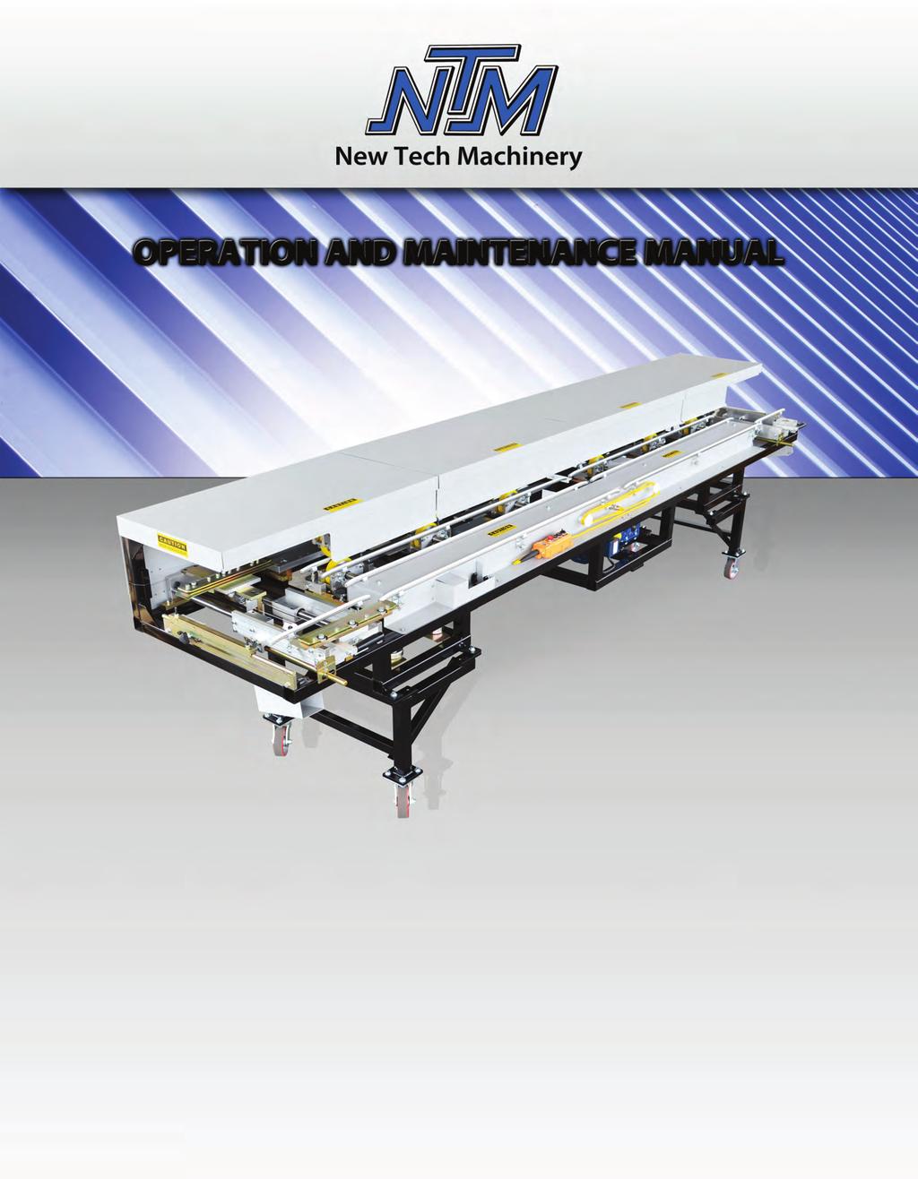
9 CHAPTER 4 MACHINE LAYOUT MACHINE LAYOUT Figure 1: Machine Overview 4
10 CHAPTER 4 MACHINE LAYOUT Figure 2: Frame Mounting Hole Pattern 5


11 CHAPTER 5 POWER REQUIREMENTS POWER REQUIREMENTS Input Power The Tapered Panel Machine input power can be ordered from the factory for either 110VAC/60Hz or 220VAC/50Hz. The machine can be changed from one power input to the other by changing out the electrical contact box as well as the motor. Option 1: 110VAC/60Hz 11A Option 2: 220VAC/50Hz 5.5A Power Cord It is very important to follow the power cord requirement prescribed by the motor and electrical control manufacturers to maintain their respective warranties. Make sure the cord being used is marked properly. Do not assume that because an extension cord looks heavy enough that it is the right gauge. Use of the wrong gauge extension cord will void the warranty on motor and electrical controls. Generator If a generator will be used to power the machine it must be large enough to handle the amp draw requirements of the motor. Contact a local generator supplier for proper sizing and refer to the specification plate on the electric motor. Use of an improperly sized generator will cause a low voltage situation of the electric motor and controls which will void the warranty. Fuse There is a 10-amp time delay fuse on the electrical controls box. This fuse protects the electrical components. If the fuse is blown, the machine will lose all functions of the machine. To replace this fuse: Locate the automotive style in-line fuse holder on the electrical controls box. It is a spring loaded twist lock holder. Push the cap in and turn CCW to open. Check the fuse with a continuity tester. If it is bad, replace with a new fuse and re-install the spring loaded cap. Figure 3: Fuse Location 6
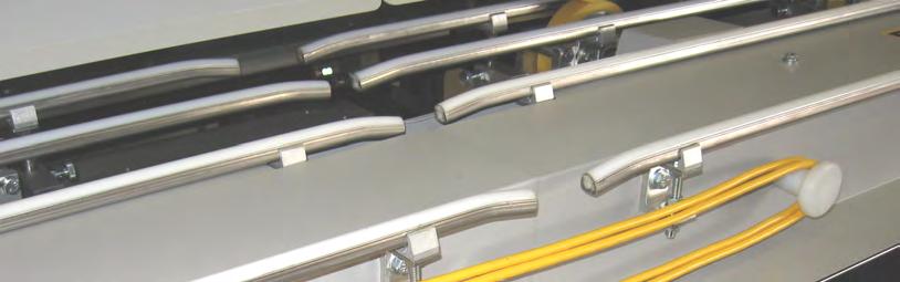
12 CHAPTER 6 CONTROLS PENDENT CONTROL JOG-RUN Switch This selector switch allows the machine to RUN continuously or JOG material through the machine. Select JOG to load material into machine and to move material through the machine in small increments until it clears all the tooling. Select RUN after material has cleared the end of the machine. STOP Button This button acts as an emergency stop for the drive system. Direction Buttons (Black buttons with arrows) These buttons are used to activate the drive system of the machine as shown. Figure 4: Pendent Control Main Control Cable The main control cable is the communication cable for the Pendent Control described above. This cable must be connected to the receptacle on the front of the machine in order for the machine to operate. The main control cable connects to a receptacle on the front cover of the machine. The cable and receptacle both have a key and slot configuration that must be aligned to connect. This prevents misalignment and damage to the pins. 7


13 CHAPTER 6 CONTROLS Figure 5: Receptacle and Cord Figure 6: Cord Coiled 8


14 CHAPTER 6 CONTROLS Figure 7: Pendent Stored Figure 8: Pendent Holster 9
15 CHAPTER 7 DRIVE SYSTEM DRIVE SYSTEM The drive system of the machine consists of six polyurethane top idle rollers and six bottom polyurethane drive rollers. The bottom drive rollers are connected together via chain and sprocket and there are chain tensioners on each assembly. The drive system is powered by a 3/4HP electric motor which transfers power through a gear reducer and sprockets to one of the center drive rollers. Drive Rollers The polyurethane drive rollers will eventually need cleaning. This will become evident when they start leaving a stripe the width of the drive roller on the formed panels that doesn t come off easily or if a panel is ran with an oily film on it. Avoid cleaning the drive rollers with harsh chemicals or solvent. These products will attack the polyurethane and cause irreversible damage. Use of these products will void the warranty on the drive rollers. Clean the rollers with mild soap and water and a rag. Caution must be taken around the moving parts of the machine during the cleaning process. Covers should be kept on the machine during operation and storage. Ultraviolet light will attack the polyurethane drive rollers and cause deterioration. Again, this type of damage is not covered under the warranty. Chain Tensioners There are two different chain tensioners on the Tapered Panel Machine. The main drive chain tensioner assembly is located on the top of the gear reducer. To add tension to the drive chain, slightly loosen bolt A and nut B then screw in bolt C. Re-tighten bolt A and nut B. 10


16 CHAPTER 7 DRIVE SYSTEM Figure 9: Main Drive Chain Tensioner The second chain tensioner is similar to the drive chain tensioner. These tensioners are located on the assemblies on the end of each drive shaft. These add tension to the chain the same way; slightly loosen bolt A and nut B then screw in bolt C. Re-tighten bolt A and nut B. Figure 10: Chain Tensioner 11


17 CHAPTER 7 DRIVE SYSTEM Chains The chains used in this system are #40 roller chain. The drive chain is a double #40 chain. Figure 11: Chains 12
18 CHAPTER 8 ENTRY GUIDE ENTRY GUIDE When forming one leg of a panel at a time such as a tapered panel, pressure must be applied to the free side of the panel to assist in guiding it into and keeping it in the forming rollers. Due to the unique nature of a tapered panel, the entry guide must be capable of moving as the panel width changes. While the entry guide changes to accommodate for the width of the panel, it also must maintain a constant pressure against the edge of the panel. There is an entry guide assembly on both ends of the machine in order to run material in both directions through the machine. Figure 12: Entry Guide Overview 13


19 CHAPTER 8 ENTRY GUIDE Entry Guide Procedure Static/Stationary Guide The material guide that is on the back of the machine is called the Static Guide. This guide is aligned with the forming rolls and locked down into place. Depending on what machine the tooling is being used from (SSR, SSH, or SSQ), align the entry guide in a similar fashioned as that machine. To adjust the position of the static guide, simply loosen the lock down handle and move the guide in or out until the alignment block lines up with the marker plate on the tooling. Loading Material The tapered panel machine is quite diverse in the types of panels that it is able to create. As a result, the entry guide can be configured in many different ways. In order to load a blank sheet of material, plug in the flat panel guide (Guide #1) into the dynamic guide assembly. Figure 13: Flat Panel Guide To load the material into the entry guide, switch the pawl bar over to the left to activate the ratcheting latch. Pull the dynamic guide out away from the machine enough to clear the material to be loaded. Slide the material into the static guide and then pull on the dynamic guide to relieve the pressure on the pawl then release the pawl by switching the bar back to the right. Allow the dynamic guide to slide back and engage the material. TIPS: To make engaging the material slightly easier, turn the flat panel guide at an angle as the dynamic guide assembly slides towards the material. 14


20 CHAPTER 8 ENTRY GUIDE Figure 14: Angle Entry Guide When running straight panels, reengage the pawl by switching the pawl bar to the left after the guide has made contact with the material. By reengaging the pawl, the guide will act much softer on the trailing edge of the material. When forming the second leg on a panel, remove the flat panel guide and install one of the two different guides with rollers depending on which profile has already been formed on the first leg. Figure 15: Guide #2 Figure 16: Guide #3 15

21 CHAPTER 8 ENTRY GUIDE Use Guide #2 for the 1 1/2 and 2 female legs and Guide #3 for all others. Figure 17: Guide #2 with Applicable Profiles 16


 attach on the top of the base rail assembly.")
22 CHAPTER 9 PROFILE CHANGEOVER PROFILE CHANGEOVER CAUTION: Always make sure the machine is shut down prior to making any adjustments. The tapered panel machine is able to accept all tool from the SSR (Multipro Jr), SSH (Multipro), and SSQ machines with the appropriate mounting bars. The Tapered Panel Machine has a base rail assembly and the SSR, SSH, and SSQ tooling mounting bars (sold separately) attach on the top of the base rail assembly. Figure 18: Tooling Base Rail Unlatch the eight latches, remove the four top covers and set them aside. Figure 19: Covers to Remove 17


23 CHAPTER 9 PROFILE CHANGEOVER Using a ½ wrench, remove the bolts holding the tooling rails to the tooling mounting bars. Store the tooling and set the hardware near the machine for use when installing the next profile. Note: the SS100, SS150, SS450/450SL, and profiles all share the same left-side rollers. Figure 20: Removing Tooling Rails SSQ Changeover Procedure The setup for tooling is similar to the SSQ machine. The rails on the Tapered Panel Machine need to be moved inward and outward to accommodate the different profile. Use the stamped identification marks in the base rail and on each tooling mounting bar shown below to locate the bars correctly. Figure 21: SSQ Left Tooling Mounting Bars 18
 for these profiles can be mounted in one of two possible positions based on the required")
24 CHAPTER 9 PROFILE CHANGEOVER Figure 22: SSQ Right Tooling Mounting Bars When the right or left bars are positioned in the machine, bolt the tooling to the mounting bars similar to the SSQ machine. Special Instructions for the SS100, SS150 and the SS450 profiles: The Left #1 Tooling Rail Assembly (L1-1) for these profiles can be mounted in one of two possible positions based on the required height of the male leg. When mounting this tooling rail assembly for use with the SS150 profile, pull it toward the outside of the machine until the two tooling rail spacers D contact the face of the side of the mounting rail #1. When mounting the tooling rail assembly for use with the SS100 or SS450 profiles push it toward the center of the machine until the Tooling Rail Backstops "E" contact the left side fixed Mount rail #1. Once it is positioned properly, tighten the two Mounting Bolts "F" using a 1/2" wrench. 19


25 CHAPTER 9 PROFILE CHANGEOVER Figure 23: Left #1 Rail-SS100, SS150, SS450 Cut a 1 triangle of material off of the leading corner and feed it into the entry guides. Figure 24: Cut Corner on Leading Edge With the pendent control switch to Jog, use the direction button(s) jog the material through the machine 6 to 8 inches at a time until it exits the last forming station. Continue jogging the material until it comes 20


26 CHAPTER 9 PROFILE CHANGEOVER in contact with the run-out stand. Be sure that the run-out stand is at the proper height, switch the control to RUN and press the directional arrow button to run the entire panel. SSH/R Changeover Procedure Arrange the tooling mounting bars in the correct orientation shown below. The bars will mount to different pads depending on which leg, right or left, is being formed. Figure 25: SSH/R Mounting Bar Orientation The SSH and SSR use similar tooling mounting bars and tooling. However, the SSH features alignment locators that assist in alignment of the tooling on top of the mounting bar. 21
27 CHAPTER 9 PROFILE CHANGEOVER Figure 26: SSH/R Tooling Mounting Bars After the tooling mounting bars (above) are bolted in the Tapered Panel Machine in the correct orientation, bolt on and align the tooling using the same procedure used on the SSH and SSR machines. 1. Bolt the tooling to the mounting bars. 2. Set the edge of the aluminum base block to dimension C when forming the right side of the panel or dimension D when forming the left side of the panel. See the following figures in order to set the entry guide. 3. Move the first tooling mounting bar in and out as needed to align the scale on the marker plate to the edge of the bar coming from the entry guide. Set the marker plate to dimension A when forming the right side or dimension B when forming the left side. 22


28 CHAPTER 9 PROFILE CHANGEOVER Figure 27: SS100 Profile Setup 23


29 CHAPTER 9 PROFILE CHANGEOVER Figure 28: SS150 Profile Setup 24


30 CHAPTER 9 PROFILE CHANGEOVER Figure 29: SS450 Profile Setup 25
31 CHAPTER 10 RUN-OUT STANDS RUN-OUT STANDS (ROS) The Run-Out Stands attach to both ends of the machine and are used to support the panel as it enters and exits the machine. They are available in 10 ft. long sections that fasten together and have adjustable legs so they can be set to the correct height. 1. Set the first run-out stand on its side and in front of the machine with the leg assembly away from the end of the machine. 2. Open the leg assembly and set it upright on the ground. 3. Lift the attachment end of the table and drop it over the 2 threaded bolts on the run-out stand bolt A shown in the figure below. 4. Loosen the 2 knob-handles on the leg assembly and allow the legs to fall free. Sight the height of the table on the left and right side adjusting it level to the machine using the knob-handles to lock the legs in place. See Figure 31 for correct and incorrect set up and details. 5. Loosen the adjustment knob (shown Figure 30) and align the run-out stand mounting bolt carriage as needed. 6. Repeat steps 1-4 for each succeeding run-out stand and attach it to the bracket on the end of the previous table. 26

32 CHAPTER 10 RUN-OUT STANDS Figure 30: Run-Out Stand Mounting Bolts 27
33 CHAPTER 10 RUN-OUT STANDS Figure 31: Run-Out Stand Height Alignment 28
34 CHAPTER 11 PROFILES PROFILES Figure 32: SS100 Roller System 29
35 CHAPTER 11 PROFILES Figure 33: SS100 Panel Profile 30
36 CHAPTER 11 PROFILES Figure 34: SS150 Roller System 31
37 CHAPTER 11 PROFILES Figure 35: SS150 Panel Profile 32
38 CHAPTER 11 PROFILES Figure 36: SS200/210A Roller System 33
39 CHAPTER 11 PROFILES Figure 37: SS200 Panel Profile 34
40 CHAPTER 11 PROFILES Figure 38: SS210A Panel Profile 35
41 CHAPTER 11 PROFILES Figure 39: SS450 Roller System 36
42 CHAPTER 11 PROFILES Figure 40: SS450 Panel Profile 37
43 CHAPTER 11 PROFILES Figure 41: SS450SL Panel Profile 38
44 CHAPTER 12 WIRING SCHEMATIC WIRING SCHEMATIC Figure 42: Wiring Schematic 39


45
TABLE OF CONTENTS CHAPTER 1 CHAPTER 2 CHAPTER 3 CHAPTER 4 CHAPTER 5 CHAPTER 6 CHAPTER 7
 TABLE OF CONTENTS CHAPTER 1 CHAPTER 2 CHAPTER 3 CHAPTER 4 CHAPTER 5 CHAPTER 6 CHAPTER 7 CHAPTER 8 CHAPTER 9 CHAPTER 10 CHAPTER 11 CHAPTER 12 CHAPTER 13 CHAPTER 14 CHAPTER 15 CHAPTER 16 CHAPTER 17 APPENDIX
It don t mean a thing If it ain t got the swing
 SWING CHUTE SAND/SALT SPREADER INSTALLATION AND OPERATING INSTRUCTIONS SWING CHUTE SPREADER MODELS: 7, 8, 9, 9.5 & 10 MANUAL FOR SPREADER SERIAL NUMBERS AFTER # 20000 It don t mean a thing If it ain t
20 Gauge Super-Speed. shoprpmachine
 Operator tor s s manual 20 Gauge Super-Speed 1 WARRANTY Our guarantee on the products we manufacture is limited to repair or replacement without charge, of any part found to be defective in materials or
Visit Our Our Our Web Site at:
 Visit Our Our Our Web Site at: ww w ww w w w w. l o c k f o rr r m e r r r. c o m 711 OGDEN AVENUE, LISLE, ILLINOIS 60532-1399 Phone (630) 964-8000 Fax (630) 964-5685 09-1998 Operator tor s manual 20 Gauge
Operations Manual Eagle 1000 Series Stretch Wrapper
 Operations Manual Eagle 1000 Series Stretch Wrapper Models A & B - 1 - READ ALL INSTRUCTIONS CONTAINED IN THIS MANUAL PRIOR TO MACHINE INSTALLATION! - 2 - Contents page 1. Machine Safety Information 1.1
Installation Manual TWM Performance Short Shifter Cobalt SS/SC, SS/TC, HHR SS, Ion Redline and Saab 9-3
 Page 1 Installation Manual TWM Performance Short Shifter Cobalt SS/SC, SS/TC, HHR SS, Ion Redline and Saab 9-3 Please Note: It is preferable to park on a flat surface, as you will have to engage and disengage
CALIFORNIA TRIMMER MOWER MAINTENANCE MANUAL
 CALIFORNIA TRIMMER MOWER MAINTENANCE MANUAL 2 Table of Contents Section 1: General Information Page Handle Assembly Instructions 4 Maintenance All Models 6 Oil Change Procedures All Models 9 Height Adjustment
IMPORTANT! DO NOT THROW AWAY THE SHIPPING CARTON AND PACKING MATERIAL
 Operator s Manual IMPORTANT! DO NOT THROW AWAY THE SHIPPING CARTON AND PACKING MATERIAL ii Table of Contents Operator Safety... 1 Introduction... 2 Unpacking and Setup... 3 Unpacking... 3 Setup... 4 ROCKET
Adjustable Angled Incline Conveyor Owners Manual with Operating Instructions
 Adjustable Angled Incline Conveyor Owners Manual with Operating Instructions Revision 012211 Table of Contents Basic Conveyor Features 3 Getting Started 4 Setting Up the Incline Conveyor 5 Belt Removal
DOOR KIT P/N , APPLICATION BEFORE YOU BEGIN KIT CONTENTS. Verify accessory fitment at Polaris.com.
 DOOR KIT P/N 2882561, 2882562 APPLICATION Verify accessory fitment at Polaris.com. BEFORE YOU BEGIN Read these instructions and check to be sure all parts and tools are accounted for. Please retain these
INSTALLATION INSTRUCTIONS
 INSTALLATION INSTRUCTIONS WARNING: NEVER EXCEED YOUR VEHICLE MANUFACTURER'S RECOMMENDED TOWING CAPACITY A20 5TH WHEEL HITCH TABLE OF CONTENTS Page# Description 1 Warnings & Precautions 2 - Assembly & Installation
LINDGREN-PITMAN General Maintenance of Lindgren-Pitman Hydraulic Systems & Equipment
 LINDGREN-PITMAN General Maintenance of Lindgren-Pitman Hydraulic Systems & Equipment Page 1 Lindgren Pitman hydraulic driven equipment is designed to give long reliable service with a minimum of repairs
<THESE INSTRUCTIONS MUST BE GIVEN TO THE END USER> 1 2 " X 1 1 2" Hex Cap Screws " Split Lock Washers " Threaded block 4
 B&W Trailer Hitches 1216 Hawaii Rd / PO Box 186 Humboldt, KS 66748 P:620.473.3664 F:620.473.3766 Companion Hitch Installation Instructions 20,000 LBS.
TIN KNOCKER FOURPLEX CLEAT FORMER INSTRUCTIONS & PARTS DIAGRAM
 TIN KNOCKER FOURPLEX CLEAT FORMER INSTRUCTIONS & PARTS DIAGRAM Sheet Metal Equipment Sales Inc. Dean P. O'Connell, President Green Bay, Wisconsin Phone - (90)-66-9966 Fax - (90)-66-9969 Website: www.sheetmetalequip.com
ALL AMERICAN BILLET. Front Drive System - Small Block Ford Installation Instructions
 ALL AMERICAN BILLET Front Drive System - Small Block Ford Installation Instructions Small Block Ford with AC & PS All American Billet Store (800) 764-0926 www.allamericanbilletstore.com Items needed for
Centrifuge Operator / Service Manual
 3000 Centrifuge Centrifuge Operator / Service Manual cat.# 26230 & 26231 The Q-sep 3000 centrifuge complies with all requirements of UL standard 3101 20, Can/CSA C22.2 No. 1010.1, and Can/CSA C22.2 No.
OLYMPIAN MODEL 740 Operation and Service Manual
 OLYMPIAN MODEL 740 Operation and Service Manual P/N 133911-102 FCI MANUAL P/N 133865-001 Data herein has been verified and validated and believed adequate for the intended use. If the machine or procedures
Heavy Duty Miniature Quick-Change Applicator (Side-Feed Type) with Mechanical or Air Feed Systems
 with Mechanical or Air Feed Systems") Heavy Duty Miniature Quick-Change Applicator (Side-Feed Type) with Mechanical or Air Feed Systems Instruction Sheet 408-8040 30 NOV 17 Rev H Ram Assembly Ram Post Locking Screw Stock Drag Drag Release
Heavy Duty Miniature Quick-Change Applicator (Side-Feed Type) with Mechanical or Air Feed Systems Instruction Sheet 408-8040 30 NOV 17 Rev H Ram Assembly Ram Post Locking Screw Stock Drag Drag Release
OPERATOR MANUAL Combo Belt Conveyor
 1 OPERATOR MANUAL Combo Belt Conveyor Document No. 11-01, Rev., 0816 2 WARNINGS THIS CONVEYOR IS DESIGNED FOR A SPECIFIC APPLICATION. CHECK FRAME AND METAL BELT FOR DAMAGE DURING SHIPMENT. READ THE MANUAL
Illustrated Parts List
 Illustrated Parts List. Ordering Parts For your convenience, replacement parts and accessories can be ordered from ARPAC by fax 24 hours a day. Please have the following information available to ensure
INSTALLATION & OWNER S MANUAL
 Rev. A, p. 1 of 13 INSTALLATION & OWNER S MANUAL Polaris Ranger (2009-) Straight UTV Steel Plow with Vehicle Mount Kit 6 Wide Snow Plow (p/n: 1POLSP) (fits the 500 H.O., 700 & 800 HD & XP) The contents
<THESE INSTRUCTIONS MUST BE GIVEN TO THE END USER> BASE BOLT BAG (RVB3500) ITEM DESCRIPTION QTY. 1 2 " X 1 1 2" Hex Cap Screws 16
 ITEM DESCRIPTION QTY. 1 2 X 1 1 2 Hex Cap Screws 16") B&W Trailer Hitches 1216 Hawaii Rd / PO Box 186 Humboldt, KS 66748 P:620.473.3664 F:620.869.9031 Companion Hitch Installation Instructions 20,000 LBS.
B&W Trailer Hitches 1216 Hawaii Rd / PO Box 186 Humboldt, KS 66748 P:620.473.3664 F:620.869.9031 Companion Hitch Installation Instructions 20,000 LBS.
Tooling Assistance Center
 Safeguards are designed into this application equipment to protect operators and maintenance personnel from most hazards during equipment operation. However, certain safety precautions must be taken by
LINDGREN-PITMAN General Maintenance of Lindgren-Pitman Hydraulic Systems & Equipment
 LINDGREN-PITMAN General Maintenance of Lindgren-Pitman Hydraulic Systems & Equipment Page 1 Lindgren-Pitman hydraulic driven equipment is designed to give long reliable service with a minimum of repairs
LOAD/ANTI TWO-BLOCK INDICATOR INSTALLATION MANUAL
 LOHD -985 SYSTEM LOAD INDICATOR 10400 35400 4 400 8100 1 LOAD/ANTI TWO-BLOCK INDICATOR INSTALLATION MANUAL 1 WARNING The LOHD 985 System servicing hydraulic and lattice cranes is designed to aid the fully
Easy Packer. Industrial Case Erecting, Packing and Taping System. User Guide
 Easy Packer Industrial Case Erecting, Packing and Taping System User Guide Easy Packer Industrial Case Erecting, Packing and Taping System User Guide Revised 04/19/2012 P/N XXXXXXX Rev A Copyright and
DAKE / JOHNSON VERTICAL BAND SAW
 DAKE / JOHNSON VERTICAL BAND SAW Model F - 6 INSTRUCTION MANUAL MODEL:F-6 SERIAL NUMBER: DATE PURCHASED: Need band saw blades? Call Dake DAKE (Division of JSJ) 724 Robbins Road Grand Haven, Michigan 4947
N. 15th Street, Middlesboro, KY TARP-N-GO SYSTEMS INSTALLATION INSTRUCTIONS
 1-800-248-7717 1002 N. 15th Street, Middlesboro, KY 40965 TARP-N-GO SYSTEMS INSTALLATION INSTRUCTIONS Congratulations on your purchase of a Mountain Tarp Tarp-N-Go tarping system. With tarping systems
Midwest Industries, Inc. Ida Grove, IA Page 1
 SSV40108HAC - Hydraulic Hoist with 120 Volt Pump SSV40108HDAC - Hydraulic Hoist, Deep Water, with 120 Volt Pump SSV40108HDC - Hydraulic Hoist with 12 Volt Pump SSV40108HDDC - Hydraulic Hoist, Deep Water,
MODEL MC1500 Installation and Operation Manual Important:
 MODEL MC1500 Installation and Operation Manual Important: This manual contains specific cautionary statements relative to worker safety. Read this manual thoroughly and follow as directed. It is impossible
Installing the CO 2 Cryogenic Oven Cooling Kit
 Installing the CO 2 Cryogenic Oven Cooling Kit Agilent 6850 Series II Network GC System Accessory G2625B This kit contains: Description Chassis 1 Chassis Cover 1 Ship kit: 1 Cooling coil 1 Coil bracket
Electric motor testing
 Electric motor testing MOTOR (MODELS EJ4-4001 AND EJ8-4001A) 23 GENERAL INFORMATION The vehicle is equipped with a 48-volt DC, shunt-wound, reversible traction motor. The shunt-wound motor is designed
USC 2020-TB/3 METRIC UM697TW OPERATION MANUAL & PARTS LISTS
 USC 2020-TB/3 METRIC UM697TW OPERATION MANUAL & PARTS LISTS TABLE OF CONTENTS TABLE OF CONTENTS...1 GENERAL SAFETY RULES...2 DIMENSIONAL DRAWING...3 SPECIFICATIONS OF USC 2020-TB...4 LEGEND OF THE MACHINE...5
RolsplicerTM. Maintenance Manual And Illustrated Parts List
 RolsplicerTM Maintenance Manual And Illustrated Parts List List of Illustrations Figure Page. Rolsplicer 3 2. Roller Adjustment 4 3. Rolsplicer 6 4. Lid Hold Down Assembly 8 5. Automatic Lid Speed Adjustment
TERMINATOR User Manual
 TERMINATOR User Manual TERMINATOR User Manual Table of Contents Section Page 1 2 3 4 5 6 7 8 9 10 11 12 13 14 15 16 17 18 19 20 21 Introduction Safety Precautions Features and Benefits Overview of the
CI 3000 Coil Inserter
 CI 3000 Coil Inserter Setup & Operator Manual Issue 1 April 02 Performance Design Inc. The CI 3000 plastic spiral inserter will bind books up to 1-1/8 (28.6mm) thick using coil diameters from 3/16 (5mm)
Operations and Service Manual. X30208 Load Bank
 Operations and Service Manual Read all instructions before using the load bank Contents 1. Components... 3 Total Assembly... 3 2) Specifications... 4 a)... 4 3) Receiving... 5 4) Safety... 5 a) Ground
EZ LINER EXPRESS USERS MANUAL
 EZ LINER EXPRESS 2013 Vehicle Service Group CHIEF'S LIMITED ONE-YEAR WARRANTY & LIABILITY Chief Automotive Technologies warrants for one year from date of installation and/or purchase any components of
One- Touch Installation Instructions
 One- Touch Installation Instructions 1 1 Height Adjustable Pivot w/ screws 9 Upper Work Surface 2 Rail Mount Knobs 10 Back Cover 3 Transformer 11 Center Pivot w/ screws 4 Support Legs 12 Left Monitor Arm
WALKIE HIGH LIFT HYDRAULIC SYSTEM
 WALKIE HIGH LIFT HYDRAULIC SYSTEM W30-40ZA [B453]; W20-30ZR [B455]; W25-30-40ZC [B454] PART NO. 1524251 2000 SRM 1025 SAFETY PRECAUTIONS MAINTENANCE AND REPAIR When lifting parts or assemblies, make sure
INSTALLATION & OWNER S MANUAL
 1 of 18 INSTALLATION & OWNER S MANUAL (*Not including cab & other accessories) A/C Alternator Kit: Yamaha Drive & Drive2 P/N: 1ACYDR2DRK Recommended it be installed with Curtis Cab: Sandstone (p/n 1GCYD1-A,
Owners Manual and Parts List. Modern Ton 33" Wheel Roller Bearing Freight Car Truck, 1 1/2 Scale Catalog Number 15T1A or 15T1B
 Owners Manual and Parts List Modern 70-100 Ton 33" Wheel Roller Bearing Freight Car Truck, 1 1/2 Scale Catalog Number 15T1A or 15T1B Features True Roller Bearing Design - Same as Prototype - Double Sealed
DESIGNED BY EXPERIENCE PLASTIC SPHERE DISPENSER USER MANUAL. Manufactured by PSDS, Inc. for sole distribution by:
 DESIGNED BY EXPERIENCE PLASTIC SPHERE DISPENSER USER MANUAL Manufactured by PSDS, Inc. for sole distribution by: AEROSTAT, INC. 8830 AIRPORT BLVD LEESBURG, FL 34788 WEBSITE: AEROSTATINC.COM TEL: 352 787-1348
1000 Park Drive Lawrence, PA Fax
 Copyright 2008. Black Box Corporation. All rights reserved. 1000 Park Drive Lawrence, PA 15055-1018 724-746-5500 Fax 724-746-0746 JANUARY 2008 RM810A-R2 RM825A-R2 RM840A-R2 RM855A-R2 RM812A-R2 RM825A-3F-R2
How to Keep your Treadmill Running
 How to Keep your Treadmill Running Buying a treadmill is hard enough. Choosing the best out of many treadmills in the market is nigh impossible. But once you ve got the treadmill you ve always wanted,
Service Manual Notes... iii. Tools Needed... v Parts:... v Technical Help... v Additional Notes... v. 1. Machine Overview Covers...
 5K Service Manual ii Table of Contents Service Manual Notes... iii Tools Needed... v Parts:... v Technical Help... v Additional Notes... v 1. Machine Overview.. 6-7 1.1. Covers...8 2. Drive Train.....9
TIMING BELT AND SPROCKET(S) REMOVAL - TIMING BELT
 REMOVAL - TIMING BELT") TIMING BELT AND SPROCKET(S) REMOVAL - TIMING BELT 1. Disconnect negative battery cable. 2. Raise vehicle on hoist. Remove right front wheel. 3. Remove belt splash shield. 4. Remove accessory drive belts.
TIMING BELT AND SPROCKET(S) REMOVAL - TIMING BELT 1. Disconnect negative battery cable. 2. Raise vehicle on hoist. Remove right front wheel. 3. Remove belt splash shield. 4. Remove accessory drive belts.
HD 7700 Setup & Operator Manual
 HD 7700 Setup & Operator Manual Issue 1 December, 01 Performance Design Inc. The Heavy Duty Ultima (HD 7700) electric punch has been designed to punch most any job that may pass through your bindery or
AXLE MOUNT MODELS: FILM ROLLER MODELS: OPERATING & SERVICE PARTS MANUAL TABLE TOP OVERWRAPPERS MODEL 625A MODEL 625A MINI MODEL 825A MODEL 875A
 OPERATING & SERVICE PARTS MANUAL TABLE TOP OVERWRAPPERS Model 625A AXLE MOUNT MODELS: MODEL 625A SINGLE ROLL WITH MOUNTING AXLES MODEL 625A MINI COMPACT SINGLE ROLL WITH MOUNTING AXLES MODEL 825A DUAL
Instructions for Fitting, Operating and Maintenance
 EN Instructions for Fitting, Operating and Maintenance Retractable Door 1 818 024 RE / 10.2011 ENGLISH Contents 1 Safety Instructions... 3 1.1 Qualified persons... 3 1.2 Symbols and signal words used...
OnBoard Drum Major Podium
 Assembly and Owner s Manual OnBoard Drum Major Podium CONTENTS CONTENTS................................................................................. 1 SAFETY...................................................................................
TABLE OF CONTENTS. Ram Assembly
 TABLE OF CONTENTS DUC Cover------------------------------------------------------------------------------------ 00 Table of Contents----------------------------------------------------------------------------
HENNIG, INC N. ALPINE ROAD MACHESNEY PARK, IL (815) (PH.) (815) (FAX)
 (PH.) (815) (FAX)") HENNIG, INC. 9900 N. ALPINE ROAD MACHESNEY PARK, IL 61115 (815)-636-9900 (PH.) (815)-636-1988 (FAX) WWW.HENNIG-INC.COM MANUAL REVISION DATE: 07/27/2016-1 - HENNIG CHIP CONVEYOR The Hennig Chip Conveyor
HENNIG, INC. 9900 N. ALPINE ROAD MACHESNEY PARK, IL 61115 (815)-636-9900 (PH.) (815)-636-1988 (FAX) WWW.HENNIG-INC.COM MANUAL REVISION DATE: 07/27/2016-1 - HENNIG CHIP CONVEYOR The Hennig Chip Conveyor
Front Drive System - Big Block Chevy Installation Instructions Big Block Chevy with AC & with PS
 Front Drive System - Big Block Chevy Installation Instructions Big Block Chevy with AC & with PS All American Billet Store (800) 764-0926 www.allamericanbilletstore.com Items needed for install Jack Jack
LC I LIPPERT COMPONENTS HYDRAULIC FULL WALL SLIDEOUT SYSTEM OPERATION AND SERVICE MANUAL
 LC I LIPPERT COMPONENTS HYDRAULIC FULL WALL SLIDEOUT SYSTEM OPERATION AND SERVICE MANUAL TABLE OF CONTENTS SYSTEM...... 3 Warning...... 3 Description..... 3 Prior to Operation... 4 4 OPERATION... Main
OPERATING INSTRUCTION MANUAL QUICK-KON AUTOMATED CRIMPING SYSTEM for Catalog Number: TNB170-ELECDIE TABLE OF CONTENTS
 OPERATING INSTRUCTION MANUAL QUICK-KON AUTOMATED CRIMPING SYSTEM for Catalog Number: TNB170-ELECDIE IMPORTANT: Read and understand all of the instructions and safety information in this manual before operating
KidWalk KidWalk II Dynamic Mobility System
 OWNER S MANUAL KidWalk KidWalk II Dynamic Mobility System Manufactured By Prime Engineering A Division of Axiom Industries, Inc. Supplier Info 70111KWOM 2 TABLE OF CONTENTS This owner s manual is organized
Serial Number: Exer 3/6 Treadmill
 Serial Number: Exer 3/6 Treadmill 0208-003L Copyright Columbus Instruments 2003 Contents Chapter 1 - Introduction System Overview...2 Specifications...2 Chapter 2 - Installation Unpacking System...4 Assembly...4
Wheel Horse. 36 Tiller. Model No & Up. Operator s Manual
 FORM NO. 8 9 Rev. A Wheel Horse 6 Tiller for Classic Garden Tractors Model No. 7970 690000 & Up Operator s Manual IMPORTANT: Read this manual carefully. It contains information about your safety and the
Riding Mowers. Z44 and Z52 Accu-Z Razor (S/N and above) SM Service Manual Printed 9/24/09
 SM Service Manual Printed 9/24/09") Riding Mowers Z44 and Z52 Accu-Z Razor (S/N 472620 and above) 23802 357-044SM Service Manual 2006 Printed 9/24/09 Copyright 2006 All rights Reserved Land Pride provides this publication as is without warranty
Riding Mowers Z44 and Z52 Accu-Z Razor (S/N 472620 and above) 23802 357-044SM Service Manual 2006 Printed 9/24/09 Copyright 2006 All rights Reserved Land Pride provides this publication as is without warranty
/ GMC SIERRA 2500 / 3500 START HERE BEFORE YOU BEGIN STEP 2
 2015-2016 CHEVROLET SILVERADO 2500 / 3500 / 2015-2016 GMC SIERRA 2500 / 3500 Z321221 / Z321221-KIT FRONT BUMPER LED LIGHT MOUNTS Parts included - (1) Driver Side Light Mount Bumper Bracket - (1) Passenger
On-A-Roll Lifter Instruction Manual for Standard Models Read Before Use!
 On-A-Roll Lifter Instruction Manual for Standard Models Read Before Use! Important instructional, safety and precautionary information! It is the user s responsibility to exercise good judgment, common
CABINET REEL OPERATING INSTRUCTIONS
 CABINET REEL OPERATING INSTRUCTIONS MODELS 15, 25, 40 & 60 SERIES RAPID-AIR CORPORATION 4601 KISHWAUKEE ST. ROCKFORD, IL 61109-2925 Phone: (815) 397-2578 Fax: (815) 398-3887 Web Site: www.rapidair.com
Tooling Assistance Center
 Safeguards are designed into this application equipment to protect operators and maintenance personnel from most hazards during equipment operation. However, certain safety precautions must be taken by
JEEP JK4 STEP SLIDER INSTALLATION BD-SS-100-JK4
 JEEP JK4 STEP SLIDER INSTALLATION BD-SS-100-JK4 PARTS LIST QTY DESCRIPTION 1 Drivers Side Slider Assembly 1 Passenger Side Slider Assembly 1 Wiring Harness and Fuse 1 Double Sided Sticky Squares and Alcohol
AUTO REWIND AIR HOSE REEL
 Model #s 46845, 46848 AUTO REWIND AIR HOSE REEL OPERATOR S MANUAL STORE THIS MANUAL IN A SAFE PLACE FOR FUTURE REFERENCE!? NEED HELP? Save time, contact us first. 888-648-8665 support@tekton.com WARNING:
Asepsis 21 Delivery Unit
 INSTALLATION INSTRUCTIONS for the Console Mounted TM Asepsis 21 Delivery Unit SECTION I - REQUIREMENTS 1. PHYSICAL REQUIREMENTS... 1 2. ELECTRICAL REQUIREMENTS... 1 3. WATER SUPPLY REQUIREMENTS... 1 4.
LK-24 PITTSBURGH LOCK MODEL 20 O PER A TO R S M A N U A L A PRODUCT OF
 LK-24 PITTSBURGH LOCK MODEL 20 O PER A TO R S M A N U A L A PRODUCT OF VER. INT. LK24-00-CE 03-2011 WARNING THISEQUIPMENTISDESIGNEDTOBEOPERATEDWITHALL COVERSSECUREDINPLACE.OPERATIONWITHOUTTHESE SAFEGUARDSMAYRESULTINCONDITIONSWHICHARE
Q&A Session for Advanced Linear Bearings and Guides 201 : Troubleshooting for Design Engineers
 Q&A Session for Advanced Linear Bearings and Guides 201 : Troubleshooting for Design Engineers Date: April 22, 2009 Q: We are currently looking into using Self Lubricating Bushings in a high-load Off-
Maintenance and Repair
 Maintenance and Repair WARNING ALWAYS shut off the engine, remove key from ignition, make sure the engine is cool, and disconnect the spark plug and positive battery terminal from the battery before cleaning,
LOOKOUT LED LIGHT BAR INSTALLATION MANUAL 7900 SERIES
 LOOKOUT LED LIGHT BAR INSTALLATION MANUAL 7900 SERIES Your purchase of a Wolo warning light is the perfect choice to compliment your vehicle. Wolo s warning lights are manufactured with the finest materials.
MMR20. Instruction Manual for Operation & Maintenance. IB International. Ph:
 MMR20 Instruction Manual for Operation & Maintenance IB International www.ibinternational.com.au Ph: 07 3399 1288 Contents Introduction... 2 Identification Data... 2 Machine Controls & Components... 3
Shaver Industries. Assembly Instructions Spring Assist Vertical Vinyl Curtain Door Projection Mount
 Shaver Industries 20 Steckle Place, Kitchener, ON N2E 2C3 Ph 1(888) 766 8328 www.shaverinc.com Assembly Instructions Spring Assist Vertical Vinyl Curtain Door Projection Mount Valued Shaver Customer: We
Bulletin Rev Operator Manual MunchMan II Conveyor
 Bulletin 13-01 Rev. 0816 Operator Manual MunchMan II Conveyor Table of Contents DESCRIPTION... 1 General... 1 Conveyor Casing Construction... 1 Drive and Take-Up... 1 Conveyor Tail End... 1 Conveyor Medium...
FD 120 Card Cutter MAINTENANCE MANUAL. MyBinding.com 5500 NE Moore Court Hillsboro, OR Toll Free: Local: /2011
 FD 120 Card Cutter 5/2011 MAINTENANCE MANUAL SAFETY PRECAUTIONS Always observe the cautions and warnings given below to prevent personal injury or property damage. The degree of danger and damage that
Coupling & Uncoupling a Tractor-Trailer
 TRAINING TOOL Coupling & Uncoupling a Tractor-Trailer DRIVING THE FUTURE 2 Coupling and Uncoupling a Tractor-Trailer TRAINING TOOL Coupling a Tractor-Trailer 1 When operating articulating vehicles such
Model 1100B CHG Terminator. Installation Instructions
 Model 1100B CHG Terminator Installation Instructions 1 Contents: 1.0 Safety Information... 3 2.0 Set-up and Adjustments... 3 3.0 Ram Adjustments... 10 4.0 Wire Termination Quality... 12 5.0 General Maintenance...
file://c:\program Files\tsocache\OFFICE_5416\SY1~us~en~file=SY131B46.htm~gen~ref...
 Page 1 of 41 SECTION 303-01B: Engine 4.6L and 5.4L 2000 F-150 Workshop Manual ASSEMBLY Procedure revision date: 01/27/2004 Engine 4.6L Special Tool(s) Compressor, Valve Spring 303-567 (T97P-6565-AH) Compressor
ELECTRIC BEDROOM SLIDEOUT SYSTEM OPERATION AND SERVICE MANUAL
 ELECTRIC BEDROOM SLIDEOUT SYSTEM OPERATION AND SERVICE MANUAL TABLE OF CONTENTS SYSTEM...... Warning...... Description..... Prior to Operation... System Maintenance..... OPERATION... Warning... Extending
Bayside Model BU2050 Installation, Maintenance, and Operation Manual
 Bayside Model BU2050 Installation, Maintenance, and Operation Manual 000000 000000 Marina Electrical Equipment, Inc. 100 Warwick Court Williamsburg, VA 23185 Toll Free: 1-855-258-3939 Fax: 1-757-258-3988
LP Series Label Feeders
 LP Series Label Feeders LPF01-001, LPF11-001 Product Guide All rights reserved Revision 6 18 June 2014 0620D-E001 LPF01-001, LFP11-001 Product Guide Hover-Davis, Inc. has checked the contents of this printed
Vickers. Overhaul Manual. Vane Pumps. Small and Large Series Combination Pumps VC(K)(S)-**-(*)*D*-6(1) VC(K)(S)-**-(*)-*-*D*-5(1)
(S)-**-(*)*D*-6(1) VC(K)(S)-**-(*)-*-*D*-5(1)") Overhaul Manual Vickers Vane Pumps Small and Large Series Combination Pumps VC(K)(S)-**-(*)*D*-6(1) VC(K)(S)-**-(*)-*-*D*-5(1) Revised 12/1/86 I-3150-S Table of Contents Section I. Introduction................................................................................
Overhaul Manual Vickers Vane Pumps Small and Large Series Combination Pumps VC(K)(S)-**-(*)*D*-6(1) VC(K)(S)-**-(*)-*-*D*-5(1) Revised 12/1/86 I-3150-S Table of Contents Section I. Introduction................................................................................
Belt Conveyor Systems
 Belt Conveyor Systems Product & Installation Manual 24-in, 36-in, and 48-in Widths Manual #: IM-704-01 i 11/14 ii Table of Contents SECTION 1 OVERVIEW 1-1 System Length 1-1 Component Dimensions 1-2 Drive
PRODUCT INFORMATION BULLETIN #3365 DIGITAL MOTOR CONTROL PLATTER SYSTEMS For Serial Number and After
 PRODUCT INFORMATION BULLETIN #3365 DIGITAL MOTOR CONTROL PLATTER SYSTEMS For Serial Number 28640996 and After Record Platter System Identification Numbers Here: Model # Serial # Table of Contents Program
Aerial Maintenance. Drip less oil or light machine oil is used on control cables, door latches, and hinges.
 Oils, greases, and other lubricants used by this Department. Engine oil SAE 15W40 is used in the crankcase of our apparatus, high-fog pump, 1981 American La France road pump transmission and also as a
OEM TM-50 Quick Start Guide
 This quick start guide provides basic setup and operating instructions for the OEM TM-50. The intended use of the OEM TM-50 Taping Machine is to produce taped reels of individually sealed and consistently
INSTALLATION MANUAL ALUMINUM & STEEL SIDE BOX
 TRUCK STORAGE SOLUTIONS SECURING YOUR REPUTATION INSTALLATION MANUAL ALUMINUM & STEEL SIDE BOX STEEL & ALUMINUM SIDE BOX WITH PACK RAT DRAWER UNITS MODELS ATTENTION: PLEASE READ AND UNDERSTAND ALL INSTRUCTIONS
PARTS & SERVICE MANUAL for RT-2VSE & RT-2VSHO TOASTER
 PARTS & SERVICE MANUAL for RT-2VSE & RT-2VSHO TOASTER Model RT-2VSE The information found in this manual will prove very helpful. Although the instructions are easy to follow, all repair procedures should
IDEAL Stripmaster Model 950 Wire Stripper #45-950
 IDEAL Stripmaster Model 950 Wire Stripper #45-950 IDEAL Stripmaster Model 950 Wire Stripper Introduction The IDEAL Stripmaster Model 950 Wire Stripper is an electrically operated, pneumatic precision production
CHAPTER S e t u p NOTICE:
 CHAPTER Setup NOTICE: Information in this manual may change without notice. Midway Games West Inc. reserves the right to make improvements in equipment function, design, or components as progress in engineering
FD 150 Document Signer
 FD 150 Document Signer OPERATOR MANUAL FIRST EDITION Thank you for purchasing the Formax FD 150 Document Signer The FD 150 has been tested and found to comply with the limits for a Class A digital device
Table of Contents WARN INDUSTRIES PAGE A1
 INSTALLATION INSTRUCTIONS AND OPERATORS GUIDE ProVantage Bucket Conversion Kit Part Number: 84133 (50 ), 83133 (54 ) and 85133 (60 ) Application: Front Mount Plow* * Not recommended for use with Center
INSTALLATION INSTRUCTIONS SEMI-HIDDEN WINCH MOUNT Part Number:70005 Application: Ford Super Duty
 INSTALLATION INSTRUCTIONS SEMI-HIDDEN WINCH MOUNT Part Number:70005 Application: Ford Super Duty Your safety, and the safety of others, is very important. To help you make informed decisions about safety,
Connector Systems Inc. SS-20 MACHINE MANUAL
 Connector Systems Inc. SS-20 MACHINE MANUAL INTRODUCTION Your SS-20 machine comes to you fully equipped and set up to terminate the style of plug you have requested. Our SS-20N will accommodate those
Assembly and Usage Instructions
 Instruction #1001966B Assembly and Usage Instructions NOT WARRANTEED AGAINST MISUSE, ABUSE, OR COMMERCIAL USE. Limited Warranty Every Caldwell product is warrantied to be free of defects in materials and
Installation Manual v1.0: Twin CP3 Fuel Injection Kit Dodge 5.9L
 Installation Manual v1.0: Twin CP3 Fuel Injection Kit 2004.5-2007 Dodge 5.9L Figure 1 - Full Kit Photo 25 Figure 2 - Hardware Kit Please read all instructions before installation. This kit is not emissions
RH800 & 2000 MAINTENANCE GUIDE
 RH800 & 2000 MAINTENANCE GUIDE PICTOGRAMS Each Signifier displayed here is specific to this User Manual. Menu Previous Advance Note Tip Example Rotary Heads Drum & Frame In-Line Filter Control Panels Gearmotors
Sofa Slideout Assembly OWNER'S MANUAL. Rev: Page 1 Sofa Slideout Owners Manual
 Sofa Slideout Assembly OWNER'S MANUAL Rev: 06.14.2016 Page 1 Sofa Slideout Owners Manual TABLE OF CONTENTS Warning, Safety, and System Requirement Information 3 Product Information 3 Prior to Operation
INSTALLATION MANUAL P2068. Level of Difficulty. Parts List. Product Image. Notes and Maintenance. Tools Required. Easy
 INSTALLATION MANUAL P2068 Parts List 1 Grille guard 1 Driver / left frame mounting bracket 1 Passenger / right frame mounting bracket 1 Driver / left top mounting bracket 1 Passenger / right top mounting
THE SSD CHUTE IS INTENDED FOR THE DESTRUCTION OF SOLID STATE MEDIA ONLY! ATTEMPTING TO SHRED ROTATIONAL DRIVES WILL VOID WARRANTY!
 Security Engineered Machinery Model 0304 Comboo SSD/HDD Shredder OPERATION AND MAINTENANCE MANUAL POP 0065 Rev. 1 Revised: 10/21/2016 Security Engineered Machinery Co., Inc E Mail: Service@SEMSHRED.com