INSTALLATION INSTRUCTIONS CHEVY C-10 4-Link Rear End
|
|
|
- Archibald Hopkins
- 5 years ago
- Views:
Transcription


1 INSTALLATION INSTRUCTIONS CHEVY C-10 4-Link Rear End Please read these instructions completely before starting your installation. Assemble suspension on vehicle before powder-coating to ensure proper fitment, and to make modifications if necessary.
2 PARTS LIST 1) Forward Crossmember 4) Control Arm Links 1) Drivers Side Axle Bracket 1) Passenger Side Axle Bracket 1) Panhard Bracket 1) Panhard Bar 1) Upper Shock Crossmember 1) Lower Shock Mount Drivers Side 1) Lower Shock Mount Passenger Side 2) Forward Struts 2) Adjustable Shocks 2) Chrome Springs 2) Forward Strut Chassis Mounts HARDWARE PACKAGE 8) 3 / 8 Stainless Steel Washers 44) 1 / 2-20 Nylock Nuts 28) 5 / 8 Washers 2) 1 / 2-20 Nylock Jam Nuts 14) 5 / 8-18 Nylock Jam Nuts 4) 3 / 8-24 Nylock Nuts 88) 1 / 2 Flat Washers 2) 1 / 2-20 X 2-3 / 4 Hex Bolts 44) 1 / 2-20 X 1-1 / 4 Hex Bolts 14) 5 / 8-18 X 3-3 / 4 Hex Bolts 4) 3 / 8-24 X 3-3 / 4 Hex Bolts 2) 1 / Pt. Flange Nuts 2) 1 / 2-20 X 3 12Pt. Flange Head


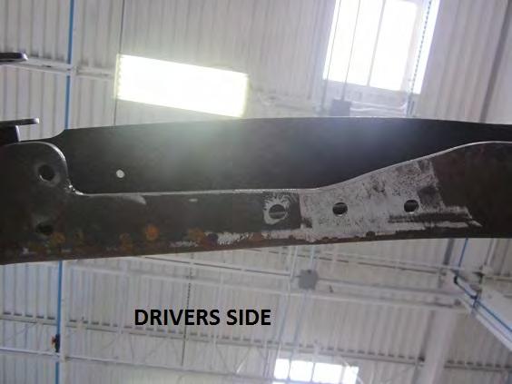
3 1) Start by jacking up your truck and supporting it on sturdy jack stands. Remove the rear wheels and bed. Disconnect the drive shaft from the rear end. Disconnect the brake lines, emergency brake cables, and fuel tank. Remove the shocks and rear end. BE SURE TO LABEL ALL HARDWARE FOR RE-INSTALLATION! At this point the rear end of your truck should be stripped down to the bare frame. Remove cross members and rear end bump stops. Leave the two rear cross members in original position. See Figures 1 and 2. Figure 1 Figure 2


4 2) The first part to install is the Front Crossmember. Prior to installation the frame rails will need to be slightly ground for fitment. Figure 3 shows the factory cross member that will need to be removed for the installation of the four link front cross member. Once that Crossmember is removed eight rivet holes will be on top and bottom of the frame rails. The holes on the bottom of the frame rail are critical for the installation of the front Crossmember. Figures 4 and 5 also show the areas on both sides of the chassis that need to be ground. Those areas are above and forward of the factory leaf spring mount. Grind approximately 3/16 on both sides to get started. See Figures 3-5. Figure 3 Figure 4 Drivers Side


5 Figure 5 Passenger Side 3) After the frame rails are ground for clearance, place the front Crossmember up in the chassis as shown in Figure 6. Use clamps to hold the Crossmember in the chassis. There should be four holes on the bottom frame rail on both sides where the factory Crossmember that was cut out. Align the bottom of the new Crossmember mounting holes with the ONE rivet hole closest to the factory spring mount. See Figure 7. Figure 6

 however it is important to check both sides")
6 Figure 7 4) To do a double check, place a square in the center of the leaf spring mount rivet shown in Figure 8. Measure from the Crossmember to the square. Our Measurement came out to be 3 ¾ from the Crossmember to the end of the ruler. There may be little plus and minus across fifteen years, ( 73-87) however it is important to check both sides until there is an equal measurement. Check measurements again before drilling. See Figure 8. Figure 8


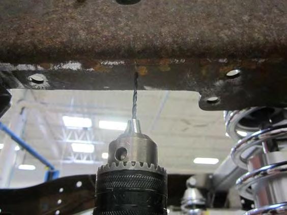
7 5) Once the Crossmember is in the correct location, it is time to drill all the mounting holes. There are four mounting holes on the bottom of each side. The alignment hole we used in Step 3 can be drilled first on both driver and passenger sides. Drill the two holes to ½. Insert a ½-20 x 1 ½ grade 8 bolt with a nylock nut on each side to hold the Crossmember in place. Drill all other holes to ½. Use a center punch and pilot drill before drilling to ½. See Figures 9 and 10. Figure 9 Figure 10 6) Install the front crossmember using eight ½-20 x 1 ½ grade 8 bolts, washers and nylock nuts. Four bolts on each side. DO NOT TIGHTEN until the top bolts are installed. 7) Install the chassis brackets as shown in Figures Figure 11 shows the drivers side and Figure 12 shows the passenger side. Bolt the drivers side bracket to the crossmember shown in Figure 13. Figure 11 Figure 12


8 8) With the upper brackets installed, use a ruler and scribe the lines for the upper mounting bolts. Measure from the center of the rivet hole from the factory Crossmember and scribe a line at 2 ½ and another at 5. These scribe lines will be the locations of the other holes for the mounting bracket. See Figure 14. Figure 13 Figure 14 9) With the lines scribed the holes and can located and drilled. Use a center punch to start the holes as seen in Figure 15. Use a 1/8 pilot drill first followed by a 3/8 for ease of ½ drilling. See Figures 15 and 16. Figure 15 Figure 16


9 10) After the holes are pilot drilled, drill all holes to ½. The factory rivet hole needs to also be drilled to ½. Use ½-20 x 1 ½ grade 8 bolts, washers and nylock nuts supplied in the hardware kit to bolt the bracket to the frame rail and Crossmember. ALL NUTS AND BOLTS CAN NOW BE TIGHTENED. See Figures Figure 17 Figure 18 Figure 19


10 11) With the front crossmember bolted in the Forward Struts can now be installed. Bolt the Forward Strut to the front Crossmember as seen in Figure 20 using 5/8-18 x 3 ¾ bolt, washers and nylock jam nut. Bolt the Forward Strut mount to the Forward Strut using 5/8-18 x 3 ¾ bolt, washers and Nylock nut. See Figures 20 and 21. Figure 20 Figure 21 12) Push the Forward Strut with the mount up to the frame rail. Center punch the ½ holes of the mount to the frame. Pilot drill and drill the ½ holes to the frame. See Figures 22 and 23. Figure 22 Figure 23


 Repeat Step 13 for the")
11 13) Bolt the Forward Strut Mount to the frame using ½-20 x 1 ½ grade 8 bolts, washers and nylock nuts. Unbolt the Forward Strut from the mount. Center punch and drill the bottom holes of the Forward Strut Mount. See Figures Figure 24 Figure 25 Figure 26 14) Repeat Step 13 for the passenger side. Tighten all bolts, washers and nuts and reinstall the Forward Struts to the Strut Mounts.


12 15) The next part to be installed is the upper shock crossmember. Place the shock crossmember in the chassis and clamp to the frame rails as shown in Figure 27. Figure 27 16) With the shock crossmember clamped snug to the frame rails, The crossmember needs to be squared and clamped tight before the ½ holes can be drilled. Place a straight edge against the front of the lower bracket and measure from the straight edge to the top factory leaf spring mount rivet. The dimension should be 27 5/8. Repeat this step for passenger side. See Figures Figure 28 Figure 29


13 Figure 30 Figure 31 17) Place the straight edge to the rear of the lower mounting bracket. Measure from the straight edge to the center of the middle rivet of the rear leaf spring mount. This dimension should be 15. Repeat this step for passenger side. See Figures Figures 32-34


14 18) Now that the shock crossmember is square front to rear, the side to side dimensions need to be corrected. Measure from the inside of the frame rail to the outside of the in board shock mount tab. The drivers side dimension should be 5 ½. The passenger side is dimension is 5. See Figures 35 and 36. Figure 35 Figure 36 19) After all dimensions are square front to rear and side to side, clamp the shock cross member tight against the frame rails. Double check all measurements one more time before drilling holes. After all dimensions are checked one last time, center punch all six lower ½ holes to the chassis. After lower holes are punched, remove crossmember and drill all six holes. Start with an 1/8 pilot drill, then use 3/8 bit followed by ½. See Figures 37 and 38. Figure 37 Figure 38


 After all four lines are scribed, flip crossmember upside down and reversed driver to passenger")
15 20) After all six holes are drilled ½, place the shock crossmember back into the chassis to double check bolt hole alignment. Bolt down the crossmember to the chassis In the four corners. Use ½-20x 1 ¼ grade 8 bolts, washers and nylock nuts to complete this step. Using a small square, scribe lines on the top frame rail parallel to the top of the mounting bracket. Repeat this step for the passenger side. See Figures 39 and 40. Figure 39 Figure 40 21) After all four lines are scribed, flip crossmember upside down and reversed driver to passenger side. Align the brackets with the scribe lines previously scribed. Once the brackets are aligned clamp the crossmember snug to the frame rail. See Figures 41 and 42. Figure 41 Figure 42


16 22) After the shock crossmember is squared to the scribe line, measure from the inside of the frame rail to the inboard shock mount repeating Step 18. The side to side dimensions are: 5 ½ from frame rail to inboard shock tab on drivers side, and 5 inside frame rail to inboard shock tab on passenger side. Double check all dimensions. See Figure 43. Once the side to side dimensions are true, clamp the crossmember tight and scribe the 8 holes to the top frame rail. See Figure 44. Figure 43 Figure 44 23) Once all 8 holes are scribed to the top frame rail, remove the shock crossmember and center punch the scribed holes. See Figure 45.Drill the holes by using a 1/8 pilot drill, 3/8 then ½ to complete the shock crossmember mounting holes. See Figures Figure 45 Figure 46


17 Figure 47 Figure 48 24) Bolt the shock crossmember into the frame using 14 ½-20x 1 ¼ grade 8 bolts, washers and nylock nuts. If upper mounting holes are slightly off, we recommend using a C clamp to move the frame rail in closer to the holes. See Figure 49. Figure 49


18 25) Install the passenger side rear shock. (Figure 50) Use a sharpie to mark the frame for spring clearance. Uninstall the shock and grind away the marked area. We recommend using a sanding drum for this step. Repeat this step for grinding the drivers side. See Figures Figure 50 Figure 51 Figure 52 Figure 53 Figure 54


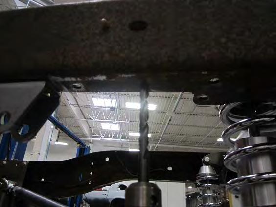
19 26) Set all four link bars to 25 ½ center to center from the bolt holes. This will be the starting point when aligning the rear end. Install the two lower links using two 5/8-18 x 3 ¾ bolts, four washers and two 5/8-18 jam nuts. Install the Ford 9 housing using stands on each axle tube. Connect the lower links to the housing finger tight. This will ease installation of the rear sway bar later. Grease fittings on bushings should be facing up. See Figures 55 and 56. Figure 55 Figure 56


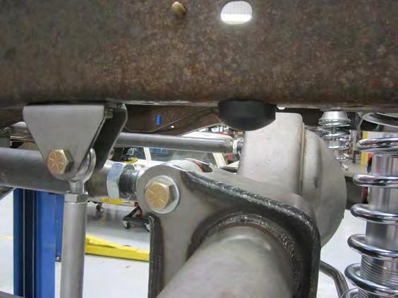
20 27) Install the two upper links using two 5/8-18 x 3 ¾ bolts, four washers and two 5/8-18 jam nuts. Grease fittings on the upper link bushings should be facing down. Opposite of lower link grease fittings. See Figures 57 and 58. Figure 57 Figure 58


21 28) Set the Panhard bar to 24 center to center from the bolt holes. This will be the starting point when aligning the rear end. Install the panhard bar using two 5/8-18 x 3 ¾ bolts, four washers and two 5/8-18 jam nuts. Grease fittings on panhard bushings should be facing up. See Figure 59. Figure 59 29) After rear end housing and Panhard bar are installed, it s time to square the rear end. First using a floor jack or stands lift the rear end housing till the panhard bar and upper and lower links are dead level. 30) Now that the rear end housing is level with the panhard bar, you can measure from the face of the rear end housing to a rivet on the factory leaf spring mount. There are many places on the factory frame to utilize, however we are going to use this rivet in Figure 61 to square this rear end housing. Same rivet for passenger side. See Figures 60 and 61. Figure 60 Figure 61

22 31) Measure from the front of the axle tube (Figure 60) to the start of the factory rivet (Figure 61). Measure both driver and passenger sides and adjust accordingly using the adjustable links. Due to factory tolerances, this dimension should be in the vicinity of 21 1/8 as seen in Figure ) To ensure rear end housing is square side to side, we will measure from the outer frame rail directly above the axle tube to the outside of the axle flange. Use a straight edge on the axle flange and a tape measure for this step. Make adjustments from the panhard bar until both driver and passenger side are the same dimensions. Dimensions will vary with different track width rear ends. See Figure 62 for example. Figure 62 33) After the rear end is squared there needs to be frame clearance for the four link mounts. The steps are similar to the shock clearance step 25. Lift the rear end housing till the mounts hit the lower frame and mark with a sharpie. The rear end housing and links will need to be removed before cutting frame rail. Cut away the frame using a cutting wheel. See Figures


23 Figure 63 Figure 64 Figure 65 Figure 66 Figure 67 Figure 68
 Set the shocks at 13 ½ center to center from the bolt hole.")

24 34) ***Install rear sway bar before installing shocks. See IN-188.*** 35) Set the shocks at 13 ½ center to center from the bolt hole. Once the shocks are assembled, install the shocks to the upper shock mount first. The upper shock mount spacer is mounted on the outboard side. This is to keep the shock straight up and down. See Figure 69. Figure 69 36) Install aluminum lower shock mount to the rear end housing. Use the 3/8-24 x 3 ½ grade 8 bolts, 3/8-24 nylock nuts and washers. See Figure 70. Figure 70

 Install both shocks so both adjusters are facing out. This is for ease of adjustment.")
25 37) Complete the shock installation by bolting the shock to the lower shock mount using 1 / 2-20 X 3 12Pt. Flange Head bolts and 1 / Pt. Flange Nuts. Make sure adjuster faces towards the rear of the truck. KEEP FLANGE BOLT LOOSE FOR BUMP STOP INSTRUCTION STEP 39. See Figures 71 and 72. Figure 71 Figure 72 38) Install both shocks so both adjusters are facing out. This is for ease of adjustment. ***Make sure all nuts and bolts are tightened before driving on the road. *** See Figure 73.

 Once the lines are scribed, remove the rear end housing from the chassis.")

26 Figure 73 39) Disconnect the lower shock mount from the aluminum shock mount. Raise the rear end housing till the housing touches the chassis. Scribe lines around the axle tubes to the chassis. See Figures Figure 75 Figure 76 40) Once the lines are scribed, remove the rear end housing from the chassis. Measure 1 ½ from either one of the scribe lines (Center of scribe lines) and scribe another mark. This will determine where the bump stop will be installed. Approximately halfway between the sides of the chassis make another scribe mark. Center punch where the scribe lines meet. Pilot drill and drill to 3/8. Install bump stop. See Figures


27 Figure 77 Figure 78 Figure 79 Figure 80 Figure 81 Figure 82
28
29 Since you are now to the point where you have a finished, running truck (we hope!) it is time to test drive it. After a few hundred miles, double check the ride height and the alignment. The springs may have settled, which would change the ride height. Re adjust the ride height before changing the alignment. After this initial settling period, the springs and bushings should have taken their final set, so you should be on your way to many miles of cruising in style.
INSTALLATION INSTRUCTIONS Chevrolet Nova Superide II Independent Front Suspension
 INSTALLATION INSTRUCTIONS 1962 1967 Chevrolet Nova Superide II Independent Front Suspension Please read these instructions completely before starting your installation. Assemble suspension on vehicle before
INSTALLATION INSTRUCTIONS CHEVROLET NOVA (NVR-301) INDEPENDENT REAR SUSPENSION
 INDEPENDENT REAR SUSPENSION") INSTALLATION INSTRUCTIONS 68-74 CHEVROLET NOVA (NVR-301) INDEPENDENT REAR SUSPENSION Please read these instructions completely before starting your installation. Assemble suspension on vehicle before powder-coating
INSTALLATION INSTRUCTIONS 68-74 CHEVROLET NOVA (NVR-301) INDEPENDENT REAR SUSPENSION Please read these instructions completely before starting your installation. Assemble suspension on vehicle before powder-coating
INSTALLATION INSTRUCTIONS 64 ½ - 70 SUPERRIDE II INDEPENDENT FRONT SUSPENSION BX-350 FOR COYOTE AND MOD ENGINES
 INSTALLATION INSTRUCTIONS 64 ½ - 70 SUPERRIDE II INDEPENDENT FRONT SUSPENSION BX-350 FOR COYOTE AND MOD ENGINES Please read these instructions completely before starting your installation. Assemble suspension
INSTALLATION INSTRUCTIONS `64 ½ - 70 MUSTANG, HEIDTS IFS, PRO-G GEN II P/N: MTF-201
 INSTALLATION INSTRUCTIONS `64 ½ - 70 MUSTANG, HEIDTS IFS, PRO-G GEN II P/N: MTF-201 Please read these instructions completely Before starting your installation. Assemble suspension on vehicle before powder-coating
USE THE PARTS LIST BELOW TO MAKE SURE YOUR KIT IS COMPLETE BEFORE INSTALLATION. IF ANY PIECES ARE MISSING, PLEASE CONTACT:
 1955-1959 Chevy Truck Rear Leaf Spring Kit Install Instructions Tech Line: 1-855-693-1259 www.totalcostinvolved.com Read and understand these instructions before starting any work! USE THE PARTS LIST BELOW
STOP---READ THIS FIRST!
 STOP---READ THIS FIRST! **Read These Entire Instructions Before Starting Anything** 2007-2010 GM 1500 TRUCK LIFT KIT INSTRUCTIONS (PART# 50700 & 50720) 5680 W. Barstow, Fresno, CA 93722 PH: (559) 226-8196
Step 5 Install the frame rail insert into the frame.
 COR-6372S, COR-6372D 63-72 C-10 Rear Coil-over KIT Tool s for the job Car Lift Floor Jack Chalks Jack Stands Standard Wrench set Standard Socket set Spring Compressor Phneumatic/ Electric Grinder Phneumatic/
STOP---READ THIS FIRST!
 STOP---READ THIS FIRST! **Read These Entire Instructions Before Starting Anything** 2007-2013 GM 1500 TRUCK LIFT KIT INSTRUCTIONS (PART# 50700 & 50720) 5680 W. Barstow, Fresno, CA 93722 PH: (559) 226-8196
INSTRUCTION G-Comp Unser Edition Rear Suspension: Chevy Nova. Kit Contents:
 INSTRUCTION 350-400 G-Comp Unser Edition Rear Suspension: 62-67 Chevy Nova Speedway Motors, Inc. 2017 Kit Contents: 350003.1 G-Comp Chassis Brace 350003.2 G-Comp Front Support 350400.1 Chevy II Unser Rear
2014 GM 1500 TRUCK STOP---READ THIS FIRST! 7" Lift KIT. **Read These Entire Instructions Before Starting Anything**
 STOP---READ THIS FIRST! **Read These Entire Instructions Before Starting Anything** 2014 GM 1500 TRUCK LIFT KIT INSTRUCTIONS (PART #50768 & #50769 ) 5680 W. Barstow, Fresno, CA 93722 PH: (559) 226-8196
CSS-C SUSPENSION LIFT KIT
 115 W. La Cadena Dr. Ste 100 Riverside, CA 92501 (951) 328-9902 phone (951) 328-9908 fax 2000-2006 CHEVROLET SILVERADO 1500 4WD CSS-C3-2 6-8 SUSPENSION LIFT KIT WARNING: CALIFORNIA SUPERTRUCKS RECOMMENDS
CHECK ALL PARTS INCLUDED IN THIS KIT TO THE PARTS LIST BEFORE INSTALLATION. IF ANY PIECES ARE MISSING, PLEASE CONTACT: TOTAL COST INVOLVED
 1949-1954 TCI Engineering Chevy Rear 4-Link Coil-Over & Air Bag Kit Installation Instructions 1-866-925-1101 www.totalcostinvolved.com Read and understand these instructions before starting any work! CHECK
Detroit Speed, Inc. Second Generation Camaro/Firebird Mini-Tub Kit Camaro/Firebird P/N: ,
 Detroit Speed, Inc. Second Generation Camaro/Firebird Mini-Tub Kit 1970-1981 Camaro/Firebird P/N: 041222, 041223 The Detroit Speed Second Generation Camaro/Firebird Rear Mini-Tub Kit is designed to accommodate
Sport Sway Bar Kit Mustang
 Sport Sway Bar Kit 22102 2005 Mustang Installation of Hotchkis Front Sway Bar 1F Raising Vehicle Securely block the rear wheels of the vehicle. Use a jack to lift up the front of the vehicle and use jack
Installation Instructions
 Installation Instructions Jeep TJ Long Arm Suspension System 1997-2002 JEEP TJ 4WD 6 1997-2002 JEEP TJ 4WD FTS24002 & BK / FTS24003 & BK / FTS44002 & BK PARTS LIST FTS24002BK Jeep TJ 6' Box Kit 1 FTS24003BK
Chrysler A-Body Tubular A-Arms Installation Instructions A-ARM INSTALLATION
 1967-1976 Dodge Demon 1112 67-72 Chrysler A-Body Tubular A-Arms Installation Instructions Thank you for your purchase of this Hotchkis Performance product. Your A-Arm set was designed with the performance
Alignment Spec. Power Rack & Pinion: 5 degrees positive Camber 0 degrees Toe-In 1/32
 333-TCIE237 1967-1969 Chevy Camaro Front Suspension 1968-1972 Chevy Nova Front Suspension 1967-1969 Pontiac Firebird Front Suspension 1-800-984-6259 www.totalcostinvolved.com 1967-1969 Chevy Camaro Front
DODGE DIESEL KIT DODGE DIESEL KIT
 69120 2009-2013 DODGE 2500 8 DIESEL KIT 2009-2012 DODGE 3500 8 DIESEL KIT Heavy Duty Long Arm Construction For Superior Ride Quality And Travel Lower Arms Constructed Of 1.75 DOM Tubing W/ Urethane Bushing
KIT # CSS-C SUSPENSION LIFT KIT
 14385 Veterans Way Moreno Valley, CA 92553 Phone: (951) 571-0212 Fax: (951) 571-0215 2001-2010 CHEVROLET SILVERADO 1500 AND 2500 HD 4WD AND 2WD PICK-UP 1999-2010 CHEVY 2500 4WD PICK-UPS 2001-2010 2500
Note: The transmission mount just happened to be upside down in this picture. (c) 2015 Total Cost Involved Engineering, Inc. All Rights Reserved.
 2015 Total Cost Involved Engineering, Inc. All Rights Reserved.") 1970-1981 Chevy Camaro & Pontiac Firebird Custom IFS Installation Instructions 1-855-693-1259 www.totalcostinvolved.com CHECK ALL PARTS INCLUDED IN THIS KIT TO THE PARTS LIST BEFORE INSTALLATION. IF ANY
1970-1981 Chevy Camaro & Pontiac Firebird Custom IFS Installation Instructions 1-855-693-1259 www.totalcostinvolved.com CHECK ALL PARTS INCLUDED IN THIS KIT TO THE PARTS LIST BEFORE INSTALLATION. IF ANY
Detroit Speed, Inc. Mini Tubs Camaro/Firebird P/N:
 Detroit Speed, Inc. Mini Tubs 1967-1969 Camaro/Firebird P/N: 040401 The Detroit Speed Mini-Tubs are inner wheel housings designed to accommodate a wider wheel and tire package. They are engineered for
RAM LIFT KIT PART# STOP! READ THIS FIRST!
 NOTE: 2014-2016 RAM 2500 4 LIFT KIT PART# 54340 STOP! READ THIS FIRST! **READ THESE ENTIRE INSTRUCTIONS BEFORE STARTING ANYTHING** or chroming, which can damage the strength and structure of the metal,
INSTRUCTION G-Comp Rear Suspension: Chevy Camaro. Kit Contents:
 INSTRUCTION 350-700 G-Comp Rear Suspension: 70-81 Chevy Camaro Speedway Motors, Inc. 2017 Kit Contents: 350700.1 G-Comp Crossmember & Chassis Brace 350700.2 G-Comp Rear Crossmember Assembly 350700.3 G-Comp
INSTALLATION INSTRUCTIONS QA1 P/N R , R , R R , R , R F100 Rear Coil-over Conversion System
 INSTALLATION INSTRUCTIONS QA1 P/N R120-170, R120-200, R120-250 R220-170, R220-200, R220-250 65-72 F100 Rear Coil-over Conversion System TOOLS AND SUPPLIES REQUIRED Floor Jack Two (2) Jack Stands Drill
Camaro Torque Arm Install Instructions
 1967-1969 Camaro Torque Arm Install Instructions 1-800-984-6259 www.totalcostinvolved.com 67 [429-4202-00] OR 68-69 [429-4202-00] REAR BRACKETS BARS Shocks Includes: Includes: Includes: Includes: 1 REAR
INSTALLATION INSTRUCTIONS
 INSTALLATION INSTRUCTIONS ----1075 North Ave. Sanger, CA 93657-3539 toll free: 800-445-3767 web: www.belltechcorp.com---- 6420 SHACKLE & HANGER KIT FORD F-350 Congratulations! You were selective enough
Detroit Speed, Inc. Mini Tubs Camaro/Firebird P/N:
 Detroit Speed, Inc. Mini Tubs 1967-1969 Camaro/Firebird P/N: 040401 The Detroit Speed Mini-Tubs are inner wheel housings designed to accommodate a wider wheel and tire package. They are engineered for
*NOTE* The following suspension system will not work with heavy duty axle housings as pictured below.
 1964 ½ - 1970 Ford Mustang Triangulated 4-Link Suspension Installation Instructions Tech Line: 1-855-693-1259 www.totalcostinvolved.com Read and understand these instructions before starting any work!
Part # Chevy Rear AirBar (One Piece Frame)
") 350 S. St. Charles St. Jasper, In. 47546 Ph. 812.482.2932 Fax 812.634.6632 www.ridetech.com Part # 11027199 55-57 Chevy Rear AirBar (One Piece Frame) Components: 1 90000160 Driver side lower axle bracket
350 S. St. Charles St. Jasper, In. 47546 Ph. 812.482.2932 Fax 812.634.6632 www.ridetech.com Part # 11027199 55-57 Chevy Rear AirBar (One Piece Frame) Components: 1 90000160 Driver side lower axle bracket
CSS-C CHEVROLET SUBURBAN & TAHOE WD AND 2WD CHEVROLET AVALANCHE WD AND 2WD 6-8 SUSPENSION LIFT KIT
 14385 Veterans Way Moreno Valley, CA 92553 Phone: (951) 571-0212 Fax: (951) 571-0215 WWW.CSTSUSPENSION.COM CSS-C3-3 2000-2006 CHEVROLET SUBURBAN & TAHOE 1500 4WD AND 2WD 2002-2006 CHEVROLET AVALANCHE 1500
USE THE PARTS LIST BELOW TO MAKE SURE YOUR KIT IS COMPLETE BEFORE INSTALLATION. IF ANY PIECES ARE MISSING, PLEASE CONTACT:
 55-59 Chevy Truck Chassis Custom IFS & 4-Link Install Instructions Tech line: 1-855-693-1259 www.totalcostinvolved.com Read and understand these instructions before starting any work! USE THE PARTS LIST
HEIDTS RF-110. INSTALLATION INSTRUCTIONS Fairlane Comet Rear 4-Link
 HEIDTS RF-110 INSTALLATION INSTRUCTIONS 66-67 Fairlane 66-67 Comet Rear 4-Link Please read these instructions completely before starting your installation. Remember the basic rule for a successful installation:
CHECK ALL PARTS INCLUDED IN THIS KIT TO THE PARTS LIST BEFORE INSTALLATION. IF ANY PIECES ARE MISSING, PLEASE CONTACT: TOTAL COST INVOLVED
 333-TCIE237 1967-1969 Chevy Camaro Front End, 1968-1972 Chevy Nova Front End 1967-1969 Pontiac Firebird Front End Suspension Installation Instructions 1-855-693-1259 www.totalcostinvolved.com CHECK ALL
2014+ DODGE RAM LIFT KIT PART# STOP! READ THIS FIRST!
 NOTE: 2014+ DODGE RAM 2500 8 LIFT KIT PART# 54320 STOP! READ THIS FIRST! **READ THESE ENTIRE INSTRUCTIONS BEFORE STARTING ANYTHING** or chroming, which can damage the strength and structure of the metal,
Part # Chevy C-10 Rear CoolRide Kit w/ StrongArms
 Components: 2 90006781 267c air spring 350 S. St. Charles St. Jasper, In. 47546 Ph. 812.482.2932 Fax 812.634.6632 www.ridetech.com Part # 11336799 63-72 Chevy C-10 Rear CoolRide Kit w/ StrongArms 1 90000626
C-10 Rear 4Link
 Part # 11367199-1973-1987 C10 Rear 4Link Recommended Tools 1973-1987 C-10 Rear 4Link Installation Table of contents Page 2... Included Components Page 3... Hardware List & Getting Started Page 4... Disassembly
67 [ ] OR [ ] REAR BRACKETS BARS Shocks Includes: Includes: Includes: Includes:
![67 [ ] OR [ ] REAR BRACKETS BARS Shocks Includes: Includes: Includes: Includes:](/thumbs/76/73590788.jpg "67 [ ] OR [ ] REAR BRACKETS BARS Shocks Includes: Includes: Includes: Includes:") 1967-1969 Firebird Mini Tub 4-Link Install Instructions 1-866-925-1101 www.totalcostinvolved.com CHECK ALL PARTS INCLUDED IN THIS KIT TO THE PARTS LIST BEFORE INSTALLATING OF THE KIT. IF ANY PIECES ARE
1967-1969 Firebird Mini Tub 4-Link Install Instructions 1-866-925-1101 www.totalcostinvolved.com CHECK ALL PARTS INCLUDED IN THIS KIT TO THE PARTS LIST BEFORE INSTALLATING OF THE KIT. IF ANY PIECES ARE
REVTEK SUSPENSION RECOMMENDS USING RED LOCTITE ON ALL FASTENERS UNLESS OTHERWISE NOTED. ALSO, HAVE THE FRONT END ALIGNMENT CHECKED AFTER INSTALLATION
 2016 TOYOTA TACOMA 4WD & PRERUNNER INSTRUCTIONS 3 SUSPENSION LIFT KIT W/BLOCKS P/N 40014 WARNING!!!! PRODUCT SAFETY LABEL MUST BE INSTALLED INSIDE THE CAB OF THE VEHICLE IN PLAIN VIEW OF ALL OCCUPANTS!
Suzuki Samurai Trail Slayer Coil Kit Instructions
 Suzuki Samurai Trail Slayer Coil Kit Instructions 1. Remove: (unbolt) *Rear axle, leaf springs, shocks, brake hoses, brake hard lines, e-brake cables, and drive shaft. *Front axle, leaf springs, shocks,
INSTALLATION INSTRUCTIONS
 INSTALLATION INSTRUCTIONS 2005-2012 Nissan Xterra/Frontier / Pathfinder PART NUMBERS: NP17500, NP17525, NP17550 FRONTIER PARTS & CORRESPONDING HARDWARE LIST XTERRA PATHFINDER ABOVE LISTED 1/2 Metal Lock
2010 Camaro SS/V Underbody Brace Installation Instructions
 2010 Camaro SS/V6 20104 Underbody Brace Installation Instructions Thank you for your purchase of this Hotchkis Performance product. Your Underbody Brace set was designed with the performance and durability
Street-Lynx By. Reilly MotorSports, Inc. Installation Manual
 Street-Lynx By Reilly MotorSports, Inc. Installation Manual 1 1- Begin by removing your original rear suspension disconnect your brake lines, E-brake cables, and remove the driveshaft. To prevent fire
Technical Support Line: (952) Hanover Ave. Lakeville, MN
 Hanover Ave. Lakeville, MN") Technical Support Line: (952) 985-5675 Email: Sales@QA1.net 21730 Hanover Ave. Lakeville, MN 55044 www.qa1.net INSTALLATION INSTRUCTIONS QA1 1967-1979 Mopar A-Body Rear 6 link Conversion System QA1 p/n
Technical Support Line: (952) 985-5675 Email: Sales@QA1.net 21730 Hanover Ave. Lakeville, MN 55044 www.qa1.net INSTALLATION INSTRUCTIONS QA1 1967-1979 Mopar A-Body Rear 6 link Conversion System QA1 p/n
INSTRUCTION S G-Comp Front Suspension: Chevy Nova Speedway Motors, Inc. 2017
 INSTRUCTION S 350-100 G-Comp Front Suspension: 62-67 Chevy Nova Speedway Motors, Inc. 2017 Kit Contents: 91035700 G-Comp Bare Subframe 350101 G-Comp Support Tubes 91035702 G-Comp Front Subframe Hardware
Installation Instructions. 6 Basic System FTS21060BK / FTS21061BK / FTS21042BK GM 2WD C1500 P/U ONLY
 Installation Instructions 6 Basic System FTS21060BK / FTS21061BK / FTS21042BK 2007-13 GM 2WD C1500 P/U ONLY 2007-13 GM 1500 Truck Basic System FTS21060BK / FTS21061BK / FTS21042BK 2007-13 GM 2WD C1500
2010 Current Ford Raptor Lower Control Arm Installation Instructions
 PREPARATION 2010 Current Ford Raptor Lower Control Arm Installation Instructions 1. Disconnect the negative terminal on the battery. Park the vehicle on level ground and set the emergency brake. 2. We
HEIDTS SUPERIDE INSTALLATION INSTRUCTIONS OPEN WHEEL SUPERIDE INDEPENDENT FRONT SUSPENSION
 HEIDTS SUPERIDE INSTALLATION INSTRUCTIONS OPEN WHEEL SUPERIDE INDEPENDENT FRONT SUSPENSION Please read these instructions completely before starting your installation. Remember the basic rule for a successful
37-39 TCI Chevy Rear 4-Link Kit Installation Instructions
 37-39 TCI Chevy Rear 4-Link Kit Installation Instructions 1-800-984-6259 www.totalcostinvolved.com Read and understand these instructions before starting any work! SUPPORT VEHICLE WITH JACK STANDS BEFORE
Super Duty Front Air Bag Installation Instructions
 2005-2010 Super Duty Front Air Bag Installation Instructions Congratulations! You have just purchased the best engineered, highest quality front air suspension kit available on the market for your 2005-2010
Part # Chevy Level 2 CoilOver Suspension Package Two Piece Frame
 350 S. St. Charles St. Jasper, In. 47546 Ph. 812.482.2932 Fax 812.634.6632 www.ridetech.com Part # 11030210 55-57 Chevy Level 2 CoilOver Suspension Package Two Piece Frame Front Components: 1 11013510
Ford F150/Raptor & F150 Lower Control Arm Installation Instructions
 2009-2010 Ford F150/Raptor & 2015-2017 F150 Lower Control Arm Installation Instructions PREPARATION 1. Disconnect the negative terminal on the battery. Park the vehicle on level ground and set the emergency
Installation Instructions
 Installation Instructions 6 Suspension System FTS25005BK / FTS25006BK 2006-2012 Nissan Frontier 2wd/4wd SHORT BED ONLY Tool List: (not included) Floor Jack & Jack Stands Assorted Metric & S.A.E Sockets
INSTALLATION GUIDE Bolt-On Drag-Race Strut Clip Chevy II
 INSTALLATION GUIDE 7702 Bolt-On Drag-Race Strut Clip 1962-67 Chevy II Description: STRUT CLIP 4130 BOLT ON 62-67 CHEVY II, INCLUDES 4130 ROUND TUBE FRAME CLIP, DOUBLE-ADJUSTABLE STRUTS, ADJUSTABLE-HEIGHT
55-59 Original Chevy Stock Chassis New Coil-Spring Front End on Original Stock Chassis
 1955-1959 Chevy Truck Coil-Spring Front End Tech line: 1-855-693-1259 www.totalcostinvolved.com Read and understand these instructions before starting any work! USE THE PARTS LIST BELOW TO MAKE SURE YOUR
2013+ DODGE RAM LIFT KIT PART# STOP! READ THIS FIRST!
 NOTE: 2013+ DODGE RAM 3500 8 LIFT KIT PART# 54324 STOP! READ THIS FIRST! **READ THESE ENTIRE INSTRUCTIONS BEFORE STARTING ANYTHING** or chroming, which can damage the strength and structure of the metal,
If you have any difficulties at all, please give us a call. Thank you and enjoy your MetalCloak Products!
 PRODUCT: TJ/LJ 3.5 Dual Rate Lift RockSport Edition READ INSTRUCTIONS IN FULL BEFORE INSTALLATION. QUESTIONS? CALL 916-631-8071 M-F 7:00 AM 5:00 PM PST The MetalCloak experience includes the ease of installation
Chevy Nova Pro-Touring Front Suspension Installation Instructions
 1962-1967 Chevy Nova Pro-Touring Front Suspension Installation Instructions 1-800-984-6259 www.totalcostinvolved.com 1 Pro-Touring Clip A-Arm Assembly Sway Bar Assembly Fender Panel Kit 8 7/16-20 * 1 ¼
2013+ DODGE RAM " Kit PART# STOP! READ THIS FIRST!
 NOTE: 2013+ DODGE RAM 3500 4" Kit PART# 54346 STOP! READ THIS FIRST! **READ THESE ENTIRE INSTRUCTIONS BEFORE STARTING ANYTHING** or chroming, which can damage the strength and structure of the metal, any
GM B-Body Street Grip
 Part # 11015010/11015110-1955-1957 GM B-Body StreetGrip Front Components 11019590 Delrin Control Arm Bushings 90003041 Tall Upper Balljoint 11012350/11012351 Front Dual Rate CoilSprings 22159847 Front
Installations Instructions for Maier Racing Front Coilover Kit MS Ford Mustang
 22215 Meekland Avenue Hayward, CA 94541 Phone: (510) 581-7600 Fax: (510) 581-2406 Installations Instructions for Maier Racing Front Coilover Kit MS-02-001 1964-1973 Ford Mustang Contents Front Coilover
STOP---READ THIS FIRST!
 STOP---READ THIS FIRST! **Read These Entire Instructions Before Starting Anything** 2003-2013 DODGE Ram 2500/3500, 8 LIFT KIT NOTE: * The factory wheels and tires WILL fit on the front of the vehicle once
2216 (STOCK) / 2224 (3 LOWER) 2WD SPORT SWAY BAR SET 97-UP DODGE DAKOTA INSTALLATION OF HOTCHKIS PERFORMANCE FRONT SWAY BAR
 / 2224 (3 LOWER) 2WD SPORT SWAY BAR SET 97-UP DODGE DAKOTA INSTALLATION OF HOTCHKIS PERFORMANCE FRONT SWAY BAR") 2216 (STOCK) / 2224 (3 LOWER) 2WD SPORT SWAY BAR SET 97-UP DODGE DAKOTA Thank you for your purchase from our line of Dodge Dakota & Durango suspension parts. Please call us at (877) 4NO-ROLL if you have
2216 (STOCK) / 2224 (3 LOWER) 2WD SPORT SWAY BAR SET 97-UP DODGE DAKOTA Thank you for your purchase from our line of Dodge Dakota & Durango suspension parts. Please call us at (877) 4NO-ROLL if you have
Part # C-10 Level 2 Complete Air Suspension System
 350 S. St. Charles St. Jasper, In. 47546 Ph. 812.482.2932 Fax 812.634.6632 www.ridetech.com Part # 11340299 63-70 C-10 Level 2 Complete Air Suspension System Front Components: 1 11330999 Front CoolRide
Chevrolet 3100 IFS Kit
 1947-54 Chevrolet 3100 IFS Kit Congratulations on your purchase on what we believe is the finest IFS kit available for 1947-54 Chevrolet pickups with stock frames. We have invested many hours into designing
FRONT DRIVELINE MODIFICATION MAY BE NECESSARY!!!!
 INSTALLATION INSTRUCTIONS FOR 2009 DODGE 2500/3500 4WD & 1500 Mega Cab 6 SUSPENSION SYSTEM PART NUMBER 7206 Requires the following parts (sold separately) for a complete installation: Front Coil Spring
INSTALLATION INSTRUCTIONS
 INSTALLATION INSTRUCTIONS --300 W PONTIAC WAY CLOVIS, CA 93612 local: 559-875-0222 fax: 559-876-2249 toll free: 800-445-3767-- 6446 5.5 REAR AXLE FLIP-KIT 2015+ FORD F-150 2WD SHORT BED Thank you for being
'99-03 CHEVROLET/GMC IFS 4WD 6" SUSPENSION SYSTEM P/N INSTALLATION INSTRUCTIONS
 1/16/04 '99-03 CHEVROLET/GMC IFS 4WD 6" SUSPENSION SYSTEM P/N. 10-41099 INSTALLATION INSTRUCTIONS NOTE: Each Lift Kit and options to Lift Kits are packaged separately. Therefore, installation procedures
1964 1/2-70 Mustang Torque Arm Rear Suspension Installation Instructions
 1964 1/2-70 Mustang Torque Arm Rear Suspension Installation Instructions 1-800-984-6259 www.totalcostinvolved.com Version 2 (c) 2008 Total Cost Involved Engineering, Inc. All Rights Reserved. Page 1 of
INSTALLATION INSTRUCTIONS Progress Technology Rear Anti-Sway Bar Honda Civic Part # No Revision (7/20/16)
") INSTALLATION INSTRUCTIONS Progress Technology Rear Anti-Sway Bar Honda Civic 96-00 Part # 62.1042 No Revision (7/20/16) WHO SHOULD INSTALL THIS PRODUCT? Progress Technology products should only be installed
INSTALLATION INSTRUCTIONS Progress Technology Rear Anti-Sway Bar Honda Civic 96-00 Part # 62.1042 No Revision (7/20/16) WHO SHOULD INSTALL THIS PRODUCT? Progress Technology products should only be installed
PARTS LIST: 8581 DODGE LONG ARM BRACKETS 03-13
 SYNERGY MFG. 870 INDUSTRIAL WAY, SAN LUIS OBISPO, CA (805) 242-0397 8580 03-12 DODGE 2500/3500 4X4, 06-08 1500 MEGACAB 4X4 LONG ARM SUSPENSION KIT V3.0 GENERAL NOTES: These instructions are also available
Maximum Motorsports Caster/Camber Plates (03-04 Cobra) - Installation Instructions
 - Installation Instructions") Maximum Motorsports Caster/Camber Plates (03-04 Cobra) - Installation Instructions The below installation instructions work for the following products: Maximum Motorsports Caster/Camber Plates (03-04 Cobra)
Maximum Motorsports Caster/Camber Plates (03-04 Cobra) - Installation Instructions The below installation instructions work for the following products: Maximum Motorsports Caster/Camber Plates (03-04 Cobra)
2008 & Newer Ford F-350 Chassis Cab 4-Link Rear Installation Instructions
 KLM18100 2686 Highway 92 - Oskaloosa, IA 52577 phone: 641.673.0468 - fax: 641.673.4168 2008 & Newer Ford F-350 Chassis Cab 4-Link Rear Installation Instructions Installation 1. Before doing anything, measure
READ AND UNDERSTAND ALL INSTRUCTIONS AND WARNINGS PRIOR TO INSTALLATION OF SYSTEM AND OPERATION OF VEHICLE.
 #021700, 021701 7 Suspension System 2000-2004 Chevy/GMC 1500 2wd Extended Cab w/ Front Coil Springs READ AND UNDERSTAND ALL INSTRUCTIONS AND WARNINGS PRIOR TO INSTALLATION OF SYSTEM AND OPERATION OF VEHICLE.
INSTALLATION OF HOTCHKIS PERFORMANCE DOUBLE ADJUSTABLE TRAILING ARMS
 1215 DOUBLE ADJUSTABLE UPPER TRAILING ARMS 67-70 CHEVROLET B-BODY This installation will require: A hydraulic jack, jack stands The following wrenches or sockets: 15/16 Adjustable wrench (1-1/4 1-9/32
1204AA Ford Mustang Double Adjustable Trailing Arms
 1204AA 79-04 Ford Mustang Double Adjustable Trailing Arms Special Tools Required for this Installation - 4 post lift or alignment rack preferable - Air Chisel, Angle Finder (Digital Preferred), Dead blow
Detroit Speed, Inc. Mini-Tub Kit Chevy Nova, Oldsmobile Omega, Pontiac Ventura P/N: &
 Detroit Speed, Inc. Mini-Tub Kit 1968-74 Chevy Nova, Oldsmobile Omega, Pontiac Ventura P/N: 041207 & 041208 Item Component Quantity 1 DSE Mini Tubs 1968-74 X-Body 2 2 Rear Upper Shock Crossmember 1 3 Upper
E-Z-GO RXV Long Travel Lift Kit 2008 & Newer Gas Installation Instructions Part# 7495 U.S.PAT U N E J K E L B C M
 E-Z-GO RXV Long Travel Lift Kit 2008 & Newer Gas Installation Instructions Part# 7495 U.S.PAT. 7581740 R S T O Q P U N E J K E D F G L B C M ITEM H A I QTY A. JAKES SUB-FRAME 1 B. TIE ROD EXTENSION 1 C.
Ford Super Duty Recoil Traction Bar System. Part#: ,123409
 Part#: 123418,123409 Ford Super Duty Recoil Traction Bar System Rev. 011017 491 W. Garfield Ave., Coldwater, MI 49036. Phone: 517-279-2135 Web/live chat: www.bds-suspension.com. E-mail: tech-bds@sporttruckusainc.com
Read and understand all instructions and warnings prior to installation of system and operation of vehicle.
 491 W. Garfield Ave., Coldwater, MI 49036 Phone: 517-279-2135 Web/live chat: www.bds-suspension.com E-mail: tech@bds-suspension.com Part#: 013001 Product: Front Box Kit Application: Ford F-100/F-150 &
INSTRUCTIONS. 4-Link Parallel With Adjustable Panhard Bar Rear Suspension System FOR MOPAR MUSCLE CARS: A-BODY (RS-5435)
") MOPAR A-BODY 4-LINK PARALLEL COIL OVER SYSTEM INSTRUCTIONS 4-Link Parallel With Adjustable Panhard Bar Rear Suspension System FOR MOPAR MUSCLE CARS: 1967-1976 A-BODY (RS-5435) Revised: 6-1-2011 Page 2
MOPAR A-BODY 4-LINK PARALLEL COIL OVER SYSTEM INSTRUCTIONS 4-Link Parallel With Adjustable Panhard Bar Rear Suspension System FOR MOPAR MUSCLE CARS: 1967-1976 A-BODY (RS-5435) Revised: 6-1-2011 Page 2
Carli Suspension Front Instructions
 Carli Suspension Front Instructions 94-08 DODGE 2500-3500 4X4 SUSPENSION SYSTEM Note: Prior to installation, carefully inspect the vehicle=s steering and drive train components. Be sure to check ball joints,
GM C10 Street Grip
 Part # 11365010/11365110-1973-1987 GM C10 StreetGrip Front Components 11369590 Delrin Control Arm Bushings 11369300 Drop Spindles 11362350/11362351 Front CoilSpring Kit 11369515 Front HQ Series Shocks
Installation Instructions
 DODGE 24K Industry Standard Rail Heavy Duty Custom Mounting Kit #2230 Gross Trailer Weight (Maximum)...24,000 lbs. Vertical Load Weight (Max. Pin Weight)...6,000 lbs. SYSTEM TOW CAPACITY Please note, in
USE THE PARTS LIST BELOW TO MAKE SURE YOUR KIT IS COMPLETE BEFORE INSTALLATION. IF ANY PIECES ARE MISSING, PLEASE CONTACT:
 1962-1967 Chevy Nova Pro-Touring Front Suspension Installation Instructions Tech line: 1-855-693-1259 www.totalcostinvolved.com Read and understand these instructions before starting any work! USE THE
5.5 Gas & 6 Diesel Radius Arm Suspension System. Dodge Ram WD Pickup Dodge Ram WD Pickup
 Part#: 012610 5.5 Gas & 6 Diesel Radius Arm Suspension System Dodge Ram 3500 4WD Pickup 2013-17 Dodge Ram 2500 4WD Pickup 2014-17 491 W. Garfield Ave., Coldwater, MI 49036. Phone: 517-279-2135 Web: www.bds-suspension.com.
60-65 Falcon, Comet & Ranchero Coil Spring IFS
 60-65 Falcon, 62-65 Comet & 62-65 Ranchero Coil Spring IFS All engine installations with this front end will require a rear sump oil pan. 289-302 Small Block Ford Motors Milodon rear sump pan holds 7 quarts
WATTS LINK INSTALLATION INSTRUCTIONS
 TOOLS REQUIRED: WL005, WL006 Hydraulic jack and jack stands Wrenches and sockets: 15mm, 18mm, 19mm, 22mm, 9/16, ¾, 15/16 Small level INSTALLATION: 1. Lift the rear of the vehicle and safely support with
GM HD Heavy Duty 4 Link Tow Kit Installation Instructions
 2001-2010 GM HD Heavy Duty 4 Link Tow Kit Installation Instructions Congratulations! You have just purchased the best engineered, highest quality air suspension kit available on the market for your 2001-2010
LIFT-507 BMF Lift Kit E-Z-Go RXV Gas or Electric Installation Instructions
 LIFT-507 BMF Lift Kit E-Z-Go RXV Gas or Electric Installation Instructions Contents of LIFT-507 E-Z-Go RXV BMF Lift Kit: a (1 ea.) BMF A-Arm Assembly b (1 ea.) Driver Side Shock Tower c (1 ea.) Passenger
2.5" & 3.5" SUSPENSION SYSTEM JEEP JK WRANGLER 2 & 4 DOOR MODELS
 2.5" & 3.5" SUSPENSION SYSTEM 2007-2018 JEEP JK WRANGLER 2 & 4 DOOR MODELS JSPEC2352 www.jksmfg.com jks@ridefox.com 517-278-1226 RV. 100818 GETTING STARTED Read all warnings, instructions, notes and cautions
»Product» Safety Warning
 RBP-LK410-40, RBP-LK410-60 RBP-LK411-60, RBP-LK411-40 Installation Instructions 2005-2015 / 2016+ Toyota Tacoma 4" and 6" Lift Systems Read and understand all instructions and warnings prior to installation
Coil-Over Kit, MMD-RC1xxxx Shock (MMCO-23)
") 3430 Sacramento Dr., Unit D San Luis Obispo, CA 93401 Telephone: 805/544-8748 Fax: 805/544-8645 www.maximummotorsports.com Coil-Over Kit, MMD-RC1xxxx Shock (MMCO-23) Supplemental Installation Notes This
3430 Sacramento Dr., Unit D San Luis Obispo, CA 93401 Telephone: 805/544-8748 Fax: 805/544-8645 www.maximummotorsports.com Coil-Over Kit, MMD-RC1xxxx Shock (MMCO-23) Supplemental Installation Notes This
EVO Manufacturing. 2.5 /3.5 Jeep Wrangler JL Enforcer Kit Instruction Manual. for all: EVO-3011, EVO-3012, EVO-3013, EVO-3014 Kits
 EVO Manufacturing 2.5 /3.5 Jeep Wrangler JL 2018+ Enforcer Kit Instruction Manual for all: EVO-3011, EVO-3012, EVO-3013, EVO-3014 Kits READ BEFORE INSTALL: 2.5 JL Enforcer/Enforcer Overland kits with either
STOP---READ THIS FIRST!
 STOP---READ THIS FIRST! **Read These Entire Instructions Before Starting Anything** 2009-2014 FORD F-150 6.5 LIFT KIT LIFT KIT INSTRUCTIONS (PART# 57000 & #57050) NOTE: * The factory wheels and tires WILL
Owner smanual. Banks Ram-Air Super-Scoop Chevy/GMC Pickups. with Installation Instructions
 Owner smanual with Installation Instructions Banks Ram-Air Super-Scoop 2007-2013 Chevy/GMC Pickups THIS MANUAL IS FOR USE WITH SYSTEM 42235, 42236 & 42237 Gale Banks Engineering 546 Duggan Avenue Azusa,
INSTALLATION GUIDE KPC 4LBO-C51
 INSTALLATION GUIDE KPC 4LBO-C1 Bolt-On 4-Link Kit 197-1987 Chevrolet and GMC C10 Pickup Description: Bolt-on, urethane-bushed 4-link rear suspension for 197-1987 Chevrolet and GMC C10 pickup. Includes
DO NOT GRIND ANY WELDS
 1 READ FIRST! PLEASE READ THROUGH ALL OF THE INSTRUCTIONS AND ENSURE THAT YOU UNDERSTAND THEM. BE SURE THAT YOU HAVE ALL THE REQUIRED GSI COMPONENTS, BASIC TOOLS, AND SKILLS. CUTTING THIS KIT REQUIRES
EVO EVO Enforcer PRO Stage 1
 EVO-201-1 EVO Enforcer PRO Stage 1 QTY PART # DESCRIPTION 1 EVO-11022B EVO Front Lower Control Arm, Driver 1 EVO-11023B EVO Front Lower Control Arm, Pass 1 EVO-11042B REARWARD BRACKET JK FRONT TRACKBAR
92-00 Civic/ Integra/ Del Sol/ Accord/ CRX
 92-00 Civic/ 94-01 Integra/ 93-97 Del Sol/ 90-97 Accord/ 92-95 CRX Front Kit Part No. 75440 www.airliftperformance.com Please read these instructions completely before proceeding with installation MN-513
Convertible MM Roll Bar (MMRB-10.1 to -10.7)
") 3430 Sacramento Dr., Unit D San Luis Obispo, CA 93401 Telephone: 805/544-8748 Fax: 805/544-8645 www.maximummotorsports.com 1983-93 Convertible MM Roll Bar (MMRB-10.1 to -10.7) The Maximum Motorsports RB-10.1
3430 Sacramento Dr., Unit D San Luis Obispo, CA 93401 Telephone: 805/544-8748 Fax: 805/544-8645 www.maximummotorsports.com 1983-93 Convertible MM Roll Bar (MMRB-10.1 to -10.7) The Maximum Motorsports RB-10.1