Part # Chevy Level 2 CoilOver Suspension Package Two Piece Frame
|
|
|
- Curtis Floyd
- 5 years ago
- Views:
Transcription

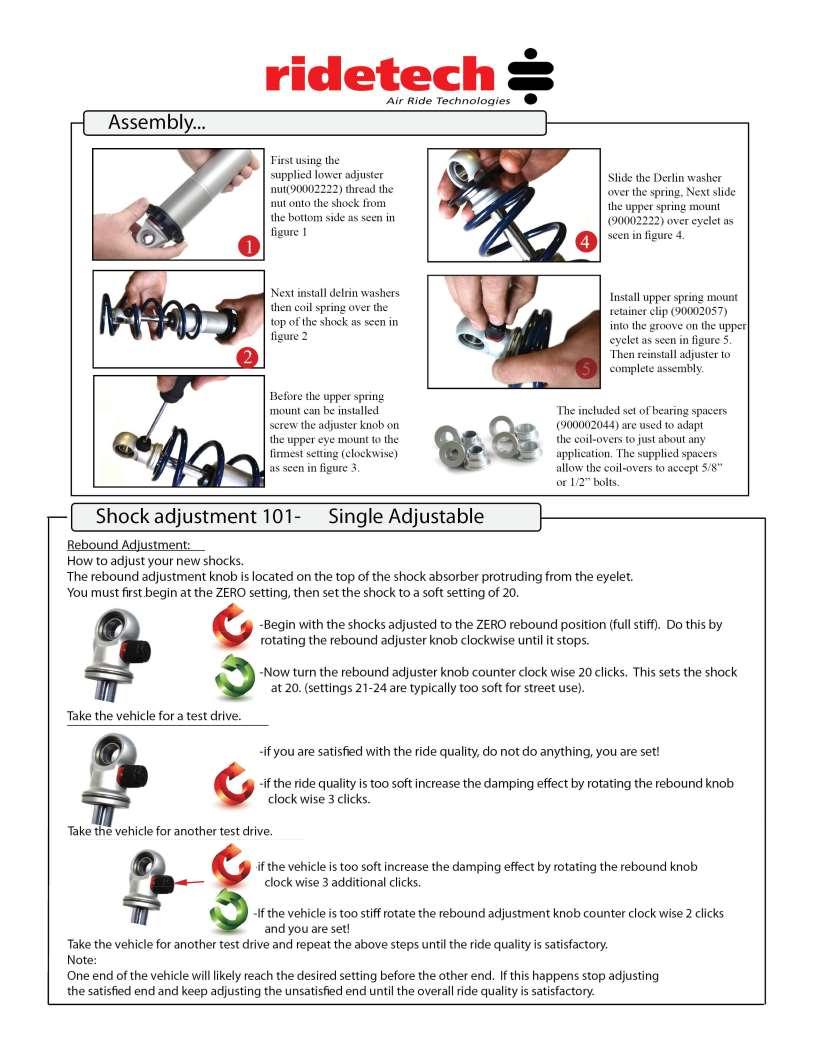
1 350 S. St. Charles St. Jasper, In Ph Fax Part # Chevy Level 2 CoilOver Suspension Package Two Piece Frame Front Components: HQ Series Front CoilOvers Front Lower StrongArms Front Upper StrongArms Rear Components: Rear AirBar 4 Link HQ Series Rear CoilOvers Components: Spanner Wrench
2 350 S. St. Charles St. Jasper, In Ph Fax Part # Chevy HQ Series Front CoilOvers For Use w/ StrongArms Shock Assembly: stroke HQ Series shock adjustable threaded stud top I.D. bearing Bearing snap ring Components: Coil spring 10 long / 600 # rate stud top base Spring retainer kit (do not use standard upper spring retainer) ¾ drop upper spring retainer Aluminum cap for Delrin ball Delrin ball upper half Delrin ball lower half Delrin Spring Washers Hardware: /16 SAE Nylok jam nut Stud top hardware
 8. Screw 9.")
3 1. Impact Forged, Monotube shock 2. Rebound adjustment knob (SA Only) 3. Upper coil spring retainer (Use ¾ dropped cap) 4. Lower coil spring retainer 5. High tensile coil spring 6. Set screw 7. Delrin Spring Washer 1. Stud top base 2. Lower Delrin ball half 3. Upper Delrin ball half 4. Aluminum cap 5. 9/16 Nylok jam nut 6. Threaded stud 7. Adjustment knob (SA Only) 8. Screw 9. Snap ring

4 1. To allow the step in the lower Delrin ball half to slide into the factory shock hole, the bushing cup will need to be removed and the hole may need to be drilled out to ¾. 2. Assemble the CoilOver then place into the coil spring pocket w/ the stud and lower Delrin ball sticking through the factory shock hole. 3. Check clearance between the upper factory spring retaining lip and stud top base. Allowing this to hit could cause the shock to break, this 4. Place the upper Delrin ball over stud, then the aluminum cap. Secure the assembly w/ the 9/16 Nylok jam nut. 5. Attach the bottom of the shock to the lower StrongArms using the spacers and hardware supplied w/ the arm.
5 350 S. St. Charles St. Jasper, In Ph Fax Part # Chevy Car Lower StrongArms For Use with Shockwaves or CoilOvers Components: Driver side lower control arm Passenger side lower control arm Lower ball joint (includes boots, castle nuts and cotter pins) Lower control arm bushing Aluminum spacers for Shockwaves Hardware: ½ -13 x 3 ¼ Gr. 5 bolt ShockWave to lower arm ½ -13 Nylok nut ShockWave to lower arm


6 Installation Instructions 1. Remove factory cross shafts from lower arm and install the factory cross shaft onto the lower StrongArm using the factory hardware. Some grinding must be done on the cross shaft to be able to slide it into the StrongArm. Replacement bushings are provided. Note: There is a driver and passenger side lower cross shaft. The extended length of the shaft should go to the front of the vehicle. 2. Install the ball joints in the lower arm pointing down. 3. Bolt the lower StrongArm to the car using the oem bolts. Note that the sway bar mount will face toward the front of the vehicle.

7 Driver Side 4. Bolt the Shockwave or CoilOver to the lower arm using the supplied 1/2" x 3 1/4" bolt and Nylok. An aluminum spacer on both sides of the eye will center the Shockwave. Note: There are holes on the lower arm near the ball joint to mount the factory bump stop. Although, it is not needed unless you are having tire clearance issues. 5. Slide the ball joint through the spindle and secure w/ castle nut and cotter pin. 6. Grease the ball joints. 7. Double check air spring clearance through full suspension travel. If any part of the Shockwave touches the frame at anytime it will damage the unit. This is not a warrantable situation.

8 Item # Description Qty. 1. Passenger side arm 1 1. Driver side arm 1 2. Aluminum bearing spacer /2-13 x 3 ¼ bolt /2"-13 Nylok nut 2 5. Cross shaft bushing 4 6. Ball joint /16-24 nut /16-24 x 3/4" bolt 8
9 350 S. St. Charles St. Jasper, In Ph Fax Part Number Chevy Upper StrongArms Components: Driver side upper arm Passenger side upper arm Ball joint (includes boot, grease fitting, castle nut & cotter pin) Cross shaft bushing Upper cross shaft large sleeve Upper cross shaft small sleeve Hardware: /8-24 x 1 ½ bolts Upper cross shaft /8 lock washers Upper cross shaft


10 Installation Instructions 1. Remove the upper control arm and cross shaft. The factory cross shaft will be reused. 2. Place the larger sleeve over the end of the upper cross shaft, slide the cross shaft through the StrongArm. Then press the bushing over the shaft. Insert the smaller sleeve inside the bushing and tighten the assembly with the 3/8-24 x 1 1/2" bolts. 3. Install the ball joint into the upper StrongArm also facing down. 4. Bolt the upper StrongArm to the frame and spindle using the factory frame bolts. 5. The upper control arm bump stop is reused. 6. Grease the ball joints.
11 55-57 Chevy Upper StrongArm Item # Description Qty. 1. Passenger side arm 1 1. Driver side arm 1 2. Ball Joint 2 3. Upper Cross shaft Large Sleeve 4 4. Cross shaft bushing 4 5. Upper Cross shaft Small Sleeve 4
12 350 S. St. Charles St. Jasper, In Ph Fax Part # Chevy Rear AirBar (Two Piece Frame) Components: Driver side lower axle bracket Passenger side lower axle bracket Front cross member ( ) Upper shock mount Upper shock mount Heim end spacer for diagonal bar Lower shockwave mount Driver Lower shockwave mount Passenger Pressed into bars Parallel Bars C-C Diagonal bar C-C /8 Shock studs Brake line tab Rod end Heim end for Diagonal link ¾ -16 Hex jam nut for rod ends Aluminum spacers lower shock bearing Hardware Kit: Part # : 4 1/2-20 x 3/4 Gr.5 bolt Lower Shockwave Mount 10 5/8-11 Nylok jam nut Rod ends 8 5/8-11 x 2 ¾ Gr.5 bolt Bar ends 2 5/8-11 x 3 Gr.5 bolt Bar ends with diagonal link mounts 2 1/2"-13 x 2 ¼ Gr.5 bolt Upper Shockwave mount 2 1/2"-13 Nylok jam nut Upper Shockwave mount 20 3/8-16 x 1 type F thread forming bolt Cross member and upper Shockwave mount 20 3/8 Lock washer Cross member and upper Shockwave mount 2 #10 x 3/4" Tek screws Brake line bracket


13 1. Raise the vehicle to a safe and comfortable working height. Use jack stands to support the vehicle with the suspension hanging freely. 2. Support the axle and remove the leaf springs, shocks, bump stops, pinion snubber and tail pipes. Refer to the factory service manual for proper disassemble procedures. 3. The parking brake brackets will be in the way of the 4 link and must be removed. Loosen the parking brake adjustment nut and remove the cable from the frame bracket. The tack weld can be broke loose with a hammer and chisel. Grind the remains of the weld smooth. 4. The rear brake line bracket on the passenger side fame rail must also be removed.


14 5. Use a couple clamps to secure the crossmember between the frame rails. Slide it forward to the edge of the body mounts. Drill the holes with a 5/16 bit and thread the 3/8 x 1 self-tapping bolts in one at a time. Do not over tighten the self-tapping bolts; they can be stripped. 6. The location of the upper Shockwave mount is determined by measuring 20 1/4 from the edge of the bracket to the large hole in the bottom of the frame. 7. Use a clamp to hold the bracket against the inside of the frame and drill the holes with a 5/16 bit. Thread a 3/8 x 1 self-tapping bolt into the frame after drilling each hole. 8. Note there is a driver and passenger side bracket and are stamped accordingly. When using the correct bracket the Shockwave will perpendicular with the ground.


15 9. How do you set the pinion angle? On a single-piece shaft you want to set it up where a line drawn through the center of the engine crankshaft or output shaft of the transmission and a line drawn through the center of the pinion are parallel to each other but not the same line. A simple way to do this is to place a digital angle finder or dial level on the front face of the lower engine pulley or harmonic balancer. This will give you a reading that is 90 degrees to the crank or output shaft unless you have real problems with your balancer. At the other end, you can place the same level or angle finder against the front face of the pinion yoke that is also at 90 degrees to the centerline. If you rotate the yoke up or down so both angles match, you have perfect alignment. Road testing will tell you if you have it right. If you accelerate and you get or increase a vibration, then the pinion yoke is too HIGH. Rotate it downward in small increments of a degree or two until the problem goes away. If you get or increase a vibration when decelerating, then the pinion yoke is too LOW. Rotate it upward to correct it.


16 10. Pinion angle must be set at ride height. At ride height there should be 4 1/2 between the axle and frame. 11. One trick to help maintain these setting while welding in the axle bracket is to tack weld a 4 1/2 long spacer between the axle and frame. 12. After setting the pinion angle, make sure the axle is centered. This can done by measuring from the axle flange in to the frame rail. 13. Install the 4 link bars into the crossmember and axle bracket, but do not tighten the bolts yet. Use the 5/8 x 2 3/4" bolts and nylocs supplied. Check the length of the bars; they should be 18 1/2" C-C. 14. There is a driver and passenger side bracket. The passenger side bracket has the diagonal link bracket welded to it. These rod ends will use a 3 bolt. You can use a large hose clamp to hold these in place temporarily. 15. Swing the axle bracket up to the axle. These brackets must be centered and aligned with the crossmember mounts before welding. The brackets should be 31 5/8 apart on the outside measurement. Then just center it between the axle flanges. 16. Tack weld the bracket to the axle. Double-check axle center, bracket alignment, and pinion angle. Remove the bars to avoid frying the bushings. Then finish welding the bracket 1 at a time in different spots to avoid warping the axle.


17 17. Bolt the lower Shockwave mount to the axle bracket using the 5/8 x 3/4 Allen bolt. Apply anti-seize to the threads. It is easier to remove the bars to install these bolts. 18. There is a driver and passenger side bracket, the correct bracket will offset the Shockwave toward the wheel. 19. Bolt the diagonal link into place with a spacer on both sides of it using a 5/8 x 2 3/4 bolt and nyloc. It should measure 30 1/4" C-C. 20. Install the parking brake cable into the new tab on the cross member. 21. With the axle at ride height snug all the 4 link bolts. These bushings are rubber and do not require lubrication. 22. Apply thread sealant onto the air fitting and screw it into the top of the shockwave. Air fitting location can be moved by rotating the bellow assembly seprate from the shock. 23. Screw the stud into the lower billet mount. Place the washer over the stud then the Shockwave followed by another washer. Apply anti-seize to the threads and then nyloc nut. 24. The Shockwave/CoilOver is held to the upper mount using a 1/2" x 2 1/4" bolt and nyloc.


18 25. Remove the spacer from between the axle and frame. 26. A new brake line tab is supplied and will mount just below the original. Make sure it clears the bar through full suspension travel. 27. Driving height will be with approximately 13" from center eye to center eye.
19 350 S. St. Charles St. Jasper, In Ph Fax Part # Chevy HQ Series Rear CoilOvers For Use w/ AirBar Shock Assembly: stroke HQ Series shock eyelet w/adjustment knob I.D. bearing Bearing snap ring Components: Coil spring 10 long / 200 # rate Spring retainer kit (do not use upper spring retainer) ¾ drop upper spring retainer Aluminum spacer for upper bearing Delrin Spring Washer Ride Height We have designed most cars to have a ride height of about 2 lower than factory. To achieve the best ride quality & handling, the shock absorber needs to be at 40-60% overall travel when the car is at ride height. This will ensure that the shock will not bottom out or top out over even the largest bumps. Measuring the shock can be difficult, especially on some front suspensions. Measuring overall wheel travel is just as effective and can be much easier. Most cars will have 4-6 of overall wheel travel. One easy way to determine where you are at in wheel travel is to take a measurement from the fender lip (center of the wheel) to the ground. Then lift the car by the frame until the wheel is just touching the ground, re-measure. This will indicate how far you are from full extension of the shock. A minimum of 1.5 of extension travel (at the wheel) is needed to ensure that the shock does not top out. If you are more than 3 from full extension of the shock then you are in danger of bottoming out the shock absorber. Adjusting Spring Height When assembling the CoilOver, screw the spring retainer tight up to the spring (0 preload). After entire weight of car is on the wheels, jounce the suspension and roll the car forward and backward to alleviate suspension bind. If the car is too high w/ 0 preload then a smaller rate spring is required. Although threading the spring retainer down would lower the car, this could allow the spring to fall out of its seat when lifting the car by the frame. If the car is too low w/ 0 preload, then preload can then be added by threading the spring retainer up to achieve ride height. On stroke shocks, up to 1.5 of preload is acceptable. On 5-7 stroke shocks, up to 2.5 of preload is acceptable. If more preload is needed to achieve ride height a stiffer spring rate is required. Too much preload may lead to coil bind, causing ride quality to suffer.
20
Part # Chevy Rear AirBar (One Piece Frame)
") 350 S. St. Charles St. Jasper, In. 47546 Ph. 812.482.2932 Fax 812.634.6632 www.ridetech.com Part # 11027199 55-57 Chevy Rear AirBar (One Piece Frame) Components: 1 90000160 Driver side lower axle bracket
350 S. St. Charles St. Jasper, In. 47546 Ph. 812.482.2932 Fax 812.634.6632 www.ridetech.com Part # 11027199 55-57 Chevy Rear AirBar (One Piece Frame) Components: 1 90000160 Driver side lower axle bracket
Part # Chevy Level 2 Air Suspension Package One Piece Frame
 350 S. St. Charles St. Jasper, In. 47546 Ph. 812.482.2932 Fax 812.634.6632 www.ridetech.com Part # 11020299 55-57 Chevy Level 2 Air Suspension Package One Piece Frame Front Components: 1 11013001 Master
Part # Chevy Level 3 Street Challenge Package One Piece Frame
 350 S. St. Charles St. Jasper, In. 47546 Ph. 812.482.2932 Fax 812.634.6632 www.ridetech.com Part # 11020399 55-57 Chevy Level 3 Street Challenge Package One Piece Frame Front Components: 1 11013011 TQ
Part # Chevy Level 3 Street Challenge Package Two Piece Frame
 350 S. St. Charles St. Jasper, In. 47546 Ph. 812.482.2932 Fax 812.634.6632 www.ridetech.com Part # 11030399 55-57 Chevy Level 3 Street Challenge Package Two Piece Frame Front Components: 1 11013002 Master
Part # GM F Body Complete CoilOver System
 350 S. St. Charles St. Jasper, In. 47546 Ph. 812.482.2932 Fax 812.634.6632 www.ridetech.com Part # 11170109 70-81 GM F Body Complete CoilOver System Front Components: 1 11173509 Front Fixed Valving CoilOvers
Part # Mustang Complete SA CoilOver Kit
 Front Components: 350 S. St. Charles St. Jasper, In. 47546 Ph. 812.482.2932 Fax 812.634.6632 www.ridetech.com Part # 12100210 67-70 Mustang Complete SA CoilOver Kit 1 12103510 Single Adjustable Front CoilOvers
Part # Cougar CoilOver System
 Front Components: 1 12103510 HQ Series Front CoilOvers 1 12102899 Lower StrongArms 1 12103699 Upper StrongArms 1 12109100 Front MuscleBar w/ PosiLinks 350 S. St. Charles St. Jasper, In. 47546 Ph. 812.482.2932
Part # Mustang Complete CoilOver Kit
 Front Components: Part # 12100109 67-70 Mustang Complete CoilOver Kit 1 12103509 Non Adjustable Front CoilOvers 1 12102899 Lower StrongArms 1 12103699 Upper StrongArms Rear Components: 1 12106509 Non Adjustable
Part # Mustang Complete CoilOver Kit
 Front Components: 1 12103509 Front CoilOvers 1 12102899 Lower StrongArms 1 12103699 Upper StrongArms 350 S. St. Charles St. Jasper, In. 47546 Ph. 812.482.2932 Fax 812.634.6632 www.ridetech.com Part # 12100109
Part # Impala Fixed Valving Coil-Over Suspension Package
 350 S. St. Charles St. Jasper, In. 47546 Part # 11060109 59-64 Impala Fixed Valving Coil-Over Suspension Package Front Components: 1 11053509 RQ Series Front Coil-overs 1 11052899 Front Lower StrongArms
Part # Impala Level 1 Complete Coil-Over System RQ Series
 350 S. St. Charles St. Jasper, In. 47546 Ph. 812.482.2932 Fax 812.634.6632 www.ridetech.com Part # 11290109 65-66 Impala Level 1 Complete Coil-Over System RQ Series Front Components: 1 11283509 RQ Series
Part # Mustang Complete NA CoilOver Kit
 Front Components: 350 S. St. Charles St. Jasper, In. 47546 Ph. 812.482.2932 Fax 812.634.6632 www.ridetech.com Part # 12090109 64-66 Mustang Complete NA CoilOver Kit 1 12093509 Non Adjustable Front CoilOvers
Part # Galaxie Air Suspension System
 350 S. St. Charles St. Jasper, In. 47546 Ph. 812.482.2932 Fax 812.634.6632 www.ridetech.com Part # 12160298 60-64 Galaxie Air Suspension System Front Components: 1 12162401 Master Series Single Adjustable
Part # GM G Body Rear CoilOver Kit Single Adjustable
 350 S. St. Charles St. Jasper, In. 47546 Ph. 812.482.2932 Fax 812.634.6632 www.ridetech.com Part # 11326110 78-88 GM G Body Rear CoilOver Kit Single Adjustable Shock Assembly: 2 24159999 5 stoke single
Part # Mustang Complete HQ Series Coil-Over Kit
 350 S. St. Charles St. Jasper, In. 47546 Ph. 812.482.2932 Fax 812.634.6632 www.ridetech.com Front Components: Part # 12090210 64-66 Mustang Complete HQ Series Coil-Over Kit 1 12093509 HQ Series Front Coil-Overs
Part # Impala Level 2 Complete Coil-Over System HQ Series
 350 S. St. Charles St. Jasper, In. 47546 Ph. 812.482.2932 Fax 812.634.6632 www.ridetech.com Part # 11290210 65-66 Impala Level 2 Complete Coil-Over System HQ Series Front Components: 1 11283509 Front HQ
Part # Impala TQ CoilOver Suspension Package
 350 S. St. Charles St. Jasper, In. 47546 Ph. 812.482.2932 Fax 812.634.6632 www.ridetech.com Part # 11040311 58 Impala TQ CoilOver Suspension Package Front Components: 1 11053511 TQ Series Front Coilovers
Part # Mustang Complete HQ Series Coil-Over Kit
 350 S. St. Charles St. Jasper, In. 47546 Ph. 812.482.2932 Fax 812.634.6632 www.ridetech.com Front Components: Part # 12090210 64-66 Mustang Complete HQ Series Coil-Over Kit 1 12093509 HQ Series Front Coil-Overs
Part # Mustang Level 2 Air Suspension System
 350 S. St. Charles St. Jasper, In. 47546 Ph. 812.482.2932 Fax 812.634.6632 www.ridetech.com Part # 12100299 67-70 Mustang Level 2 Air Suspension System Front Components: 1 12103001 Single Adjustable Series
Part # Impala Air Suspension System
 350 S. St. Charles St. Jasper, In. 47546 Ph. 812.482.2932 Fax 812.634.6632 www.ridetech.com Part # 11040298 58 Impala Air Suspension System Front Components: 1 11053001 HQ Series Front Shockwaves 1 11052899
350 S. St. Charles St. Jasper, In Ph Fax
 350 S. St. Charles St. Jasper, In. 47546 Ph. 812.482.2932 Fax 812.634.6632 www.ridetech.com Part # 11167197 67-69 GM F Body AirBar Components: 1 90000527 Upper cradle assembly 1 90002077 Lower axle bracket
Part # Mustang Coil-Over System
 350 S. St. Charles St. Jasper, In. 47546 Ph. 812.482.2932 Fax 812.634.6632 www.ridetech.com Front Components: 1 12093509 HQ Series Front Coil-Overs Part # 12090201 64-66 Mustang Coil-Over System 1 12099599
Part # Mustang Rear AirBar
 350 S. St. Charles St. Jasper, In. 47546 Ph. 812.482.2932 Fax 812.634.6632 www.ridetech.com Part # 12087199 64-70 Mustang Rear AirBar Components: 1 90000513 Lower Shockwave mount 1 90000514 Lower Shockwave
Part # Lincoln Level 2 Air Suspension Package
 350 S. St. Charles St. Jasper, In. 47546 Ph. 812.482.2932 Fax 812.634.6632 www.ridetech.com Part # 12060299 64-69 Lincoln Level 2 Air Suspension Package Front Components: 1 12060999 CoolRide Kit 1 12060601
Part # Impala Air Suspension System
 350 S. St. Charles St. Jasper, In. 47546 Ph. 812.482.2932 Fax 812.634.6632 www.ridetech.com Part # 11060298 59-64 Impala Air Suspension System Front Components: 1 11053001 HQ Series Front Shockwaves 1
Part # GM X Body Complete CoilOver System
 350 S. St. Charles St. Jasper, In. 47546 Ph. 812.482.2932 Fax 812.634.6632 www.ridetech.com Part # 11260210 68-74 GM X Body Complete CoilOver System Front Components: 1 11263510 Front HQ Series CoilOvers
Part # GM F Body Complete CoilOver System
 350 S. St. Charles St. Jasper, In. 47546 Ph. 812.482.2932 Fax 812.634.6632 www.ridetech.com Part # 11160109 67-69 GM F Body Complete CoilOver System Front Components: 1 11163509 Front Non-adjustable CoilOvers
Part # GM F Body Complete CoilOver System
 350 S. St. Charles St. Jasper, In. 47546 Ph. 812.482.2932 Fax 812.634.6632 www.ridetech.com Part # 11160210 67-69 GM F Body Complete CoilOver System Front Components: 1 11163510 Front HQ Series CoilOvers
Part # GM F Body Rear R-Joint Bolt-in 4 Link GM F Body Rear Bolt-in 4Link. Table of contents. Installation Instructions
 Part # 11167199-1967-1969 GM F Body Rear R-Joint Bolt-in 4 Link Recommended Tools 1967-1969 GM F Body Rear Bolt-in 4Link Installation Table of contents Page 2-3... Included Components Page 4... Hardware
Installation Instructions
 Part # 12087199-1965-1970 Mustang Rear Bolt-in 4 Link Recommended Tools 1965-1970 Mustang Rear Bolt-in 4 Link Installation Table of contents Page 2... Included components Page 3... Hardware List and Getting
Part # GM F Body CoilOver System
 350 S. St. Charles St. Jasper, In. 47546 Ph. 812.482.2932 Fax 812.634.6632 www.ridetech.com Part # 11160201 67-69 GM F Body CoilOver System Front Components: 1 11163510 Front HQ Series CoilOvers 1 11162899
Part # GM G Body Air Suspension System
 350 S. St. Charles St. Jasper, In. 47546 Ph. 812.482.2932 Fax 812.634.6632 www.ridetech.com Part # 11320298 78-88 GM G Body Air Suspension System Front Components: 1 11323001 HQ Series Front Shockwaves
Part # C-10 Level 2 Complete Air Suspension System
 350 S. St. Charles St. Jasper, In. 47546 Ph. 812.482.2932 Fax 812.634.6632 www.ridetech.com Part # 11340299 63-70 C-10 Level 2 Complete Air Suspension System Front Components: 1 11330999 Front CoolRide
Part # GM A Body Complete SA CoilOver System
 Part # 11240210 68-72 GM A Body Complete SA CoilOver System Front Components: 1 11243510 Front Single-adjustable CoilOvers 1 11222899 Front Lower StrongArms 1 11223699 Front Upper StrongArms 1 11009300
Part # GM A Body Complete CoilOver System
 350 S. St. Charles St. Jasper, In. 47546 Ph. 812.482.2932 Fax 812.634.6632 www.ridetech.com Part # 11230109 64-67 GM A Body Complete CoilOver System Front Components: 1 11233509 Front Non-adjustable CoilOvers
Part # Mustang Complete Level 2 Air Suspension Kit
 350 S. St. Charles St. Jasper, In. 47546 Ph. 812.482.2932 Fax 812.634.6632 www.ridetech.com Front Components: Part # 12090299 64-66 Mustang Complete Level 2 Air Suspension Kit 1 12093001 HQ Series Front
Installation Instructions Camaro Level 2 Coilover. Part # Camaro Level 2 CoilOver System.
 Part # 00-99-00 Camaro Level CoilOver System Front Components: 0 Front CoilOver Strut Recommended Tools Rear Components: 60 Rear Coilover Miscellaneous Components: 85000000 Spanner Wrench 99-00 Camaro
Part # Mustang Tru-Turn Suspension Package
 350 S. St. Charles St. Jasper, In. 47546 Ph. 812.482.2932 Fax 812.634.6632 www.ridetech.com Part # 12099599 64-66 Mustang Tru-Turn Suspension Package Front Components: 1 12093699 Upper Strong Arms 1 12092899
C5/C6 Level 2 Coilover
 Part # 5020-998-203 C5/C6 Level 2 CoilOver System Front Components: 530 Front Coilovers Recommended Tools Rear Components: 560 Rear Coilover Miscellaneous Components: 85000000 Spanner Wrench 998-203 C5/C6
Part # Mustang Level 1 Air Suspension System
 350 S. St. Charles St. Jasper, In. 47546 Ph. 812.482.2932 Fax 812.634.6632 www.ridetech.com Part # 12090199 66-66 Mustang Level 1 Air Suspension System Front Components: 1 12092409 NA Series Front Shock
# C5/C6
 Part # 00-998-0 C/C Level CoilOver System Front Components: 0 Front Coilovers Recommended Tools Rear Components: 0 Rear Coilover Miscellaneous Components: 8000000 Spanner Wrench 998-0 C/C Level Coilover
C5/C6 Level 3 Coilover
 Part # 11510311-1998-2013 C5/C6 Level 3 CoilOver System Front Components: 11513111 Front Coilovers Recommended Tools Rear Components: 11516111 Rear Coilover Miscellaneous Components: 85000000 Spanner Wrench
Part # Mustang Tru-Turn Suspension Package
 350 S. St. Charles St. Jasper, In. 47546 Ph. 812.482.2932 Fax 812.634.6632 www.ridetech.com Part # 12099599 64-66 Mustang Tru-Turn Suspension Package Front Components: 1 12093699 Upper Strong Arms 1 12092899
Installation Instructions Mustang Level 2 Coilover. Part # Mustang Level 2 CoilOver System.
 Part # 22020-979-989 Mustang Level 2 CoilOver System Front Components: 2230 Front CoilOver Strut Recommended Tools Rear Components: 2260 Rear Coilover 225899 Rear Lower StrongArms 226699 Rear Upper StrongArms
Part # Mustang Complete Level 3 Air Suspension Kit
 350 S. St. Charles St. Jasper, In. 47546 Ph. 812.482.2932 Fax 812.634.6632 www.ridetech.com Front Components: Part # 12090399 64-66 Mustang Complete Level 3 Air Suspension Kit 1 12093011 TQ Series Front
2015 up Mustang Front HQ CoilOver Strut
 Part # 70-05 up Mustang Recommended Tools 05 up Mustang Front HQ CoilOver Strut Installation Table of contents Page... Included components Page... Disassembly and Getting Started Page... Strut Assembly
63-70/71-72 C-10 Coilover System
 Part # 11340201(63-70)/113520201(71-72) - C10 CoilOver System Front Components: 11342699/11352699 Front StrongArm System 11349300/11359300 Front Spindles and Caliper Brackets 11333510 Front Coilovers 11369100
Installation Instructions
 Part # 11310-1963-1967 C HQ Front CoilOvers Recommended Tools 1963-1967 C HQ Series Front CoilOvers Table of contents Page... Included components Page 3... CoilOver Assembly Page 4... CoilOver Page...
73-87 C-10 Coilover System
 Part # 11360201-73-87 C10 CoilOver System Front Components: 11362699 Front StrongArm System 11369300 Front Spindles and Caliper Brackets 11363510 Front Coilovers 11369100 Front MuscleBar Recommended Tools
Part # Mustang Air Suspension System
 350 S. St. Charles St. Jasper, In. 47546 Ph. 812.482.2932 Fax 812.634.6632 www.ridetech.com Front Components: Part # 12090298 64-66 Mustang Air Suspension System 1 12093001 HQ Series Front Shockwaves 1
Part # Chevy C-10 Rear CoolRide Kit w/ StrongArms
 Components: 2 90006781 267c air spring 350 S. St. Charles St. Jasper, In. 47546 Ph. 812.482.2932 Fax 812.634.6632 www.ridetech.com Part # 11336799 63-72 Chevy C-10 Rear CoolRide Kit w/ StrongArms 1 90000626
Part # GM X Body Level 2 Complete Air Suspension System
 350 S. St. Charles St. Jasper, In. 47546 Ph. 812.482.2932 Fax 812.634.6632 www.ridetech.com Part # 11260299 68-74 GM X Body Level 2 Complete Air Suspension System Front Components: 1 11163001 HQ Series
Part # GM F-Body Rear CoilOvers
 Part # 1116111-198-00 GM F-Body Rear CoilOvers Recommended Tools 8-0 F-Body TQ Series Rear Coilovers Table of contents Page... Included components Page 3... Hardware List and Getting Started Page 4...
ARF10600-LCA Chevy Coolride Kit with lower Strong Arms
 350 S. St. Charles St. Jasper, In. 47546 Ph. 812.482.2932 Fax 812.634.6632 www.ridetech.com ARF10600-LCA 58-64 Chevy Coolride Kit with lower Strong Arms 1 LCA10600 pair of CoolRide lower Strong Arms (includes
Hardware List...In the box (Kit# )
") Part # 33799-963-97 C0 Rear StrongArms Recommended Tools 963-97 C-0 Rear StrongArms Table of contents Page... Included components Page 3... Hardware List and Getting Started Page 4... Disassembly and Front
Part # 33799-963-97 C0 Rear StrongArms Recommended Tools 963-97 C-0 Rear StrongArms Table of contents Page... Included components Page 3... Hardware List and Getting Started Page 4... Disassembly and Front
Part # GM G Body Tru-Turn Suspension Package
 350 S. St. Charles St. Jasper, In. 47546 Ph. 812.482.2932 Fax 812.634.6632 www.ridetech.com Part # 11329599 78-88 GM G Body Tru-Turn Suspension Package Front Components: 1 11323699 Upper Strong Arms 1
2015 up Mustang Front HQ CoilOver Strut
 Part # 13110-015 up Mustang Recommended Tools 015 up Mustang Front HQ CoilOver Strut Installation Table of contents Page... Included components Page 3... Disassembly and Getting Started Page... Strut Assembly
Part # GM A Body Air Suspension System
 350 S. St. Charles St. Jasper, In. 47546 Ph. 812.482.2932 Fax 812.634.6632 www.ridetech.com Part # 11240298 68-72 GM A Body Air Suspension System Front Components: 1 11243001 HQ Series Front Shockwaves
Installation Instructions
 Part # 115110-005 up Mustang Recommended Tools 005-up Mustang Front HQ CoilOver Strut Installation Table of contents Page... Included components Page... Disassembly and Getting Started Page... Strut Assembly
1. Remove the front struts by first disconnecting the ABS wire and brake line(retain hardware) from the factory strut.
 from the factory strut.") Part # 12153111-2005 up Mustang Recommended Tools 2005-up Mustang Front TQ CoilOver Strut Installation Table of contents Page 2... Included components Page 3... Disassembly and Getting Started Page 4...
Part # 12153111-2005 up Mustang Recommended Tools 2005-up Mustang Front TQ CoilOver Strut Installation Table of contents Page 2... Included components Page 3... Disassembly and Getting Started Page 4...
C-10 StrongArms
 Part # 11342699(63-70)/11352699(71-72) - C10 StrongArms Recommended Tools 1963-1972 C-10 StrongArms Installation Table of contents Page 2... Included components Page 3... Upper Control Arm Components Page
GM B-Body Street Grip
 Part # 11015010/11015110-1955-1957 GM B-Body StreetGrip Front Components 11019590 Delrin Control Arm Bushings 90003041 Tall Upper Balljoint 11012350/11012351 Front Dual Rate CoilSprings 22159847 Front
Part # GM A Body CoilOver System
 350 S. St. Charles St. Jasper, In. 47546 Ph. 812.482.2932 Fax 812.634.6632 www.ridetech.com Part # 11240210 68-72 GM A Body CoilOver System Front Components: 1 11243510 Front Single-adjustable CoilOvers
C-10 Rear 4Link
 Part # 11367199-1973-1987 C10 Rear 4Link Recommended Tools 1973-1987 C-10 Rear 4Link Installation Table of contents Page 2... Included Components Page 3... Hardware List & Getting Started Page 4... Disassembly
82-03 S10/S15 ShockWave System
 Part # 11390297-82-03 GM S10/S15 ShockWave System Front Components: 11399959 Front TruTurn Control Arm System 11393001 Front ShockWave 11399100 Front MuscleBar Recommended Tools Rear Components: 11397199
Disassembly. Getting Started (IF USING BEARING UPPER MOUNT SKIP TO STEP 9) Installation Instructions.
 Installation Instructions.") Part # 00-00 up Camaro Recommended Tools 00-up Camaro Front CoilOver Strut Table of contents Page... Included components Page... Disassembly and Getting Started Page... CoilSpring ssembly and Bearing Option
Part # 00-00 up Camaro Recommended Tools 00-up Camaro Front CoilOver Strut Table of contents Page... Included components Page... Disassembly and Getting Started Page... CoilSpring ssembly and Bearing Option
GM C10 Street Grip
 Part # 11365010/11365110-1973-1987 GM C10 StreetGrip Front Components 11369590 Delrin Control Arm Bushings 11369300 Drop Spindles 11362350/11362351 Front CoilSpring Kit 11369515 Front HQ Series Shocks
Part # Mustang Mustang Front CoilOver Strut
 Part # 3110-1979-1989 Mustang Recommended Tools 1979-1989 Mustang Front CoilOver Strut Installation Table of contents Page 2... Included components Page 3... Disassembly and Getting Started Page 4... Upper
350 S. St. Charles St. Jasper, In Ph Fax
 350 S. St. Charles St. Jasper, In. 47546 Ph. 81.48.93 Fax 81.634.663 www.ridetech.com Part # 1304411 Mopar LX Platform Front Shockwave TQ Series 05-08 Magnum / 05-Up 300C / 06-Up Charger / 08-Up Challenger
Slide the billet aluminum cap over the bushing and secure with the 3/8-16 x 2 1/2 socket head allen and locknuts provided.
 Slide the billet aluminum cap over the bushing and secure with the 3/8-16 x 2 1/2 socket head allen and locknuts provided. Put the urethane bushings into the upper antiroll-bar-link eyebolt. Coat the bushings
INSTRUCTION G-Comp Unser Edition Rear Suspension: Chevy Nova. Kit Contents:
 INSTRUCTION 350-400 G-Comp Unser Edition Rear Suspension: 62-67 Chevy Nova Speedway Motors, Inc. 2017 Kit Contents: 350003.1 G-Comp Chassis Brace 350003.2 G-Comp Front Support 350400.1 Chevy II Unser Rear
1000 Series Bellow, 2.0 Stud/Trunnion 2.9 Shock
 Part # 11012401-55-57 GM B-Body Front HQ Shockwave, OEM Control Arms Recommended Tools 1000 Series Bellow, 2.0 Stud/Trunnion 2.9 Shock THE CONTROL ARMS NEED TO BE REINFORCED IN THE AREA THAT THE TRUNNION
Installation Instructions
 Installation Installation Part # 11503111-2010 up Camaro Recommended Tools 2010-up Camaro TQ Front CoilOver Strut Installation Table of contents Page 2... Included Components Page 3... Disassembly and
Installation Instructions
 Part # 11210299-1993-2002 GM F Body Level 2 Shockwave System Front Components: 11212401 Front Shockwaves Recommended Tools Rear Components: 11215401 Rear Shockwaves Compressor System 30334000 Digital 3
Next, set the bar level and tighten it down. Do this on both the driver and passenger sides.
 Next, set the bar level and tighten it down. Do this on both the driver and passenger sides. Using two tape measures, measure the outside width at the front and the rear of the tubes. The front dimension
First, check and record the camber and caster readings, they will be adjusted later.
 First, check and record the camber and caster readings, they will be adjusted later. The caliper-mounting bosses are machined perpendicular to the spindle so they are an excellent place for the level.
1000 Series Bellow, 2.00 Stud/Eye 3.6 Shock
 Part # 11323001-78-88 GM G-Body Front HQ Series Shockwave Recommended Tools 1000 Series Bellow, 2.00 Stud/Eye 3.6 Shock Table of contents Page 2... Included components Page 3-4... Shockwave Page 5-6...
Part # Galaxie Level 1 Complete Air Suspension System
 350 S. St. Charles St. Jasper, In. 47546 Ph. 812.482.2932 Fax 812.634.6632 www.ridetech.com Part # 12160199 60-64 Galaxie Level 1 Complete Air Suspension System Front Components: 1 12162409 Front RQ Series
Installation Instructions Mustang Air Suspension. Part # Mustang Air Suspension System.
 Part # 12120298-1979-1989 Mustang Air Suspension System Recommended Tools Front Components: 12122401 Front ShockWave Strut Rear Components: 12125401 RearShockWave 12125899 Rear Lower StrongArms 12126699
Technical Support Line: (952) Hanover Ave. Lakeville, MN
 Hanover Ave. Lakeville, MN") Technical Support Line: (952) 985-5675 Email: Sales@QA1.net 21730 Hanover Ave. Lakeville, MN 55044 www.qa1.net INSTALLATION INSTRUCTIONS QA1 1967-1979 Mopar A-Body Rear 6 link Conversion System QA1 p/n
Technical Support Line: (952) 985-5675 Email: Sales@QA1.net 21730 Hanover Ave. Lakeville, MN 55044 www.qa1.net INSTALLATION INSTRUCTIONS QA1 1967-1979 Mopar A-Body Rear 6 link Conversion System QA1 p/n
Detroit Speed, Inc. QUADRA Link Rear Suspension Chevy II P/N:
 Detroit Speed, Inc. QUADRA Link Rear Suspension 1962-1967 Chevy II P/N: 041707 Detroit Speed, Inc. QUADRAlink is a great way to upgrade from original leaf spring suspension. Unlike our competitors, Detroit
MM Rear Coil-Over Kit - Koni Single and Double Adjustable Shocks (MMCO-5)
") 3430 Sacramento Dr., Unit D San Luis Obispo, CA 93401 Telephone: 805/544-8748 Fax: 805/544-8645 www.maximummotorsports.com MM Rear Coil-Over Kit - Koni Single and Double Adjustable Shocks (MMCO-5) Read
3430 Sacramento Dr., Unit D San Luis Obispo, CA 93401 Telephone: 805/544-8748 Fax: 805/544-8645 www.maximummotorsports.com MM Rear Coil-Over Kit - Koni Single and Double Adjustable Shocks (MMCO-5) Read
USE THE PARTS LIST BELOW TO MAKE SURE YOUR KIT IS COMPLETE BEFORE INSTALLATION. IF ANY PIECES ARE MISSING, PLEASE CONTACT:
 60-65 Ford Falcon Triangulated 4-Link Suspension Installation Instructions Tech Line: 1-855-693-1259 www.totalcostinvolved.com Read and understand these instructions before starting any work! USE THE PARTS
Alignment Spec. Power Rack & Pinion: 5 degrees positive Camber 0 degrees Toe-In 1/32
 333-TCIE237 1967-1969 Chevy Camaro Front Suspension 1968-1972 Chevy Nova Front Suspension 1967-1969 Pontiac Firebird Front Suspension 1-800-984-6259 www.totalcostinvolved.com 1967-1969 Chevy Camaro Front
Carli Suspension Front Instructions
 Carli Suspension Front Instructions 94-08 DODGE 2500-3500 4X4 SUSPENSION SYSTEM Note: Prior to installation, carefully inspect the vehicle=s steering and drive train components. Be sure to check ball joints,
*NOTE* The following suspension system will not work with heavy duty axle housings as pictured below.
 1964 ½ - 1970 Ford Mustang Triangulated 4-Link Suspension Installation Instructions Tech Line: 1-855-693-1259 www.totalcostinvolved.com Read and understand these instructions before starting any work!
INSTRUCTION S G-Comp Front Suspension: Chevy Nova Speedway Motors, Inc. 2017
 INSTRUCTION S 350-100 G-Comp Front Suspension: 62-67 Chevy Nova Speedway Motors, Inc. 2017 Kit Contents: 91035700 G-Comp Bare Subframe 350101 G-Comp Support Tubes 91035702 G-Comp Front Subframe Hardware
Detroit Speed, Inc. QUADRA Link Rear Suspension Camaro/Firebird P/N:
 Detroit Speed, Inc. QUADRA Link Rear Suspension 1967-1969 Camaro/Firebird P/N: 041703 Figure 1 Item Component Quantity 1 Upper Link Front Pocket-Left 1 2 Upper Link Front Pocket-Right 1 3 Upper Shock Crossmember
Part # Mopar LX Level 1 Air Suspension System
 Part # 13040199 05-14 Mopar LX Level 1 Air Suspension System Front Components: 1 1304409 Front RQ ShockWave Kit for Stock Lower Arms Rear Components: 1 13044099 Rear CoolRide Kit 1 13040709 RQ Series Rear
HEIDTS RF-110. INSTALLATION INSTRUCTIONS Fairlane Comet Rear 4-Link
 HEIDTS RF-110 INSTALLATION INSTRUCTIONS 66-67 Fairlane 66-67 Comet Rear 4-Link Please read these instructions completely before starting your installation. Remember the basic rule for a successful installation:
55-59 Original Chevy Stock Chassis New Coil-Spring Front End on Original Stock Chassis
 1955-1959 Chevy Truck Coil-Spring Front End Tech line: 1-855-693-1259 www.totalcostinvolved.com Read and understand these instructions before starting any work! USE THE PARTS LIST BELOW TO MAKE SURE YOUR
RHINO SUSPENSION SYSTEM INSTALLATION INSTRUCTIONS
 PARTS INCLUDED: 2 FRONT UPPER A-ARMS 2 FRONT LOWER A-ARMS 2 UNI-BALL JOINTS 2 UNI-BALL JOINT STUDS 2 UNI-BALL JOINT CAPS 2 RETAINING RINGS 1 FRONT SHOCK ASSEM. 2 DELRON STEERING STOPS 2 SHOCK MOUNT SPACERS
MM Rear Coil-Over Kit - Bilstein Shocks (MMCO-3)
") 3430 Sacramento Dr., Unit D San Luis Obispo, CA 93401 Telephone: 805/544-8748 Fax: 805/544-8645 www.maximummotorsports.com MM Rear Coil-Over Kit - Bilstein Shocks (MMCO-3) Read all instructions before
3430 Sacramento Dr., Unit D San Luis Obispo, CA 93401 Telephone: 805/544-8748 Fax: 805/544-8645 www.maximummotorsports.com MM Rear Coil-Over Kit - Bilstein Shocks (MMCO-3) Read all instructions before
INSTALLATION INSTRUCTION 88088
 INSTALLATION INSTRUCTION 88088 For Rancho Suspension Systems RS6588 & RS6589: FORD F-150 READ ALL INSTRUCTIONS THOROUGHLY FROM START TO FINISH BEFORE BEGINNING INSTALLATION Rev B IMPORTANT NOTES! WARNING:
'99-03 CHEVROLET/GMC IFS 4WD 6" SUSPENSION SYSTEM P/N INSTALLATION INSTRUCTIONS
 1/16/04 '99-03 CHEVROLET/GMC IFS 4WD 6" SUSPENSION SYSTEM P/N. 10-41099 INSTALLATION INSTRUCTIONS NOTE: Each Lift Kit and options to Lift Kits are packaged separately. Therefore, installation procedures
INSTALLATION INSTRUCTION 88146
 INSTALLATION INSTRUCTION 88146 Rev H FOR RANCHO SUSPENSION SYSTEM RS6547: 4WD SUBURBAN/YUKON XL, 4WD TAHOE/YUKON, & 4WD AVALANCHE READ ALL INSTRUCTIONS THOROUGHLY FROM START TO FINISH BEFORE BEGINNING
Installation Guide for the JK Wrangler 4-Inch Suspension System with FlexArms
 INSTALLATION GUIDE Tera Manufacturing, Inc. 5251 South Commerce Dr. Murray, Utah 84107 Phone/801.288.2585 Fax/801.713.2313 www.teraflex.biz Installation Guide for the JK Wrangler 4-Inch Suspension System
IRS-151 INSTALLATION INSTRUCTIONS `55-57 CHEVY INDEPENDENT REAR SUSPENSION
 IRS-151 INSTALLATION INSTRUCTIONS `55-57 CHEVY INDEPENDENT REAR SUSPENSION Please read these instructions completely before starting your installation. Remember the basic rule for a successful installation:
Suspension System RS6582B
 Suspension System RS6582B Tahoe/Yukon READ ALL INSTRUCTIONS THOROUGHLY FROM START TO FINISH BEFORE BEGINNING INSTALLATION IMPORTANT NOTES! WARNING: This suspension system will enhance the off-road performance
INSTALLATION INSTRUCTION 88094
 INSTALLATION INSTRUCTION 88094 FOR RANCHO SUSPENSION SYSTEM RS6594B 4WD & 2WD NISSAN TITAN READ ALL INSTRUCTIONS THOROUGHLY FROM START TO FINISH BEFORE BEGINNING INSTALLATION Rev D IMPORTANT NOTES! WARNING: