Part # GM F Body CoilOver System
|
|
|
- Domenic Hudson
- 5 years ago
- Views:
Transcription

1 350 S. St. Charles St. Jasper, In Ph Fax Part # GM F Body CoilOver System Front Components: Front HQ Series CoilOvers Front Lower StrongArms Front Upper StrongArms RideTech Tall Spindles Front MuscleBar Rear Components: Rear AirBar Bolt-on 4 Link Rear HQ Series CoilOvers Components: Spanner Wrench
2 350 S. St. Charles St. Jasper, In Ph Fax Shock Assembly: Part # GM F Body HQ Series Front CoilOvers For Use w/ StrongArms and Tall Spindle stroke HQ Series shock threaded stud top I.D. bearing bearing snap ring Components: Coil spring 8 long / 700 # rate stud top base Spring retainer kit (included upper and lower spring retainer, screw & clip) Aluminum cap for Delrin ball Delrin ball upper half Delrin ball lower half Delrin Spring Washer Hardware: /16 SAE Nylok jam nut Stud top hardware
 8. Screw 9.")
3 1. Impact Forged, Monotube shock 2. Rebound adjustment knob (SA Only) 3. Upper coil spring retainer 4. Lower coil spring retainer 5. High tensile coil spring 6. Set screw 7. Delrin Spring Washer 1. Stud top base 2. Lower Delrin ball half 3. Upper Delrin ball half 4. Aluminum cap 5. 9/16 Nylok jam nut 6. Threaded stud 7. Adjustment knob (SA Only) 8. Screw 9. Snap ring


4 1. Inspect the factory welds attaching the upper shock bracket to the frame. Re-weld if necessary. 2. To allow the step in the lower Delrin ball half to slide into the factory shock hole, the hole will need to be drilled out to ¾. 3. Assemble the CoilOver then place into the coil spring pocket w/ the stud and lower Delrin ball sticking through the factory shock hole. 4. Check clearance between the upper spring retainer and stud base with the factory coil spring retainer this area may need trimmed to get full shock movement. 5. Place the upper Delin ball over stud, then the aluminum cap. Secure the assembly w/ the 9/16 Nylok jam nut. 6. Attach the bottom of the shock to the lower StrongArms using the spacers and hardware supplied w/ the arm.
5 350 S. St. Charles St. Jasper, In Ph Fax Part # GM F Body & GM X Body Lower StrongArms For Use w/ Shockwave or CoilOver Components: Driver side lower arm Passenger side lower arm Ball joint (includes boot, grease fitting, castle nut & cotter pin) Inner bushing sleeve -.5 I.D. x.75 O.D. x long Delrin bushing half 1.5 O.D Aluminum spacers shock to lower arm Hardware: /2-13 x 3 ¼ Gr.5 bolt Shockwave to lower arm /2"-13 x 3 ½ Gr.5 bolt Lower arm to frame /2-13 Nylok Nut Lower arm /8 x 5 ½ USS bolt Sway bar end link /8 USS Nylok Nut Sway bar end link & Steering Stop /8 x 1 ¼ USS bolt Steering stop

6 Installation Instructions 1. After removing the factory lower control arm, clean the bushing mounting surfaces on the frame. 2. Fasten the lower arm to the frame with the ½ x 3 ½ bolts and Nylok nuts supplied. Note: On some cars the frame brackets may be pinched and will need to be spread back apart to allow bushing to slide in. 3. Swing the lower StrongArm up to the Shockwave and secure with the ½ x 3 ¼ bolt and Nylok nut, an aluminum spacer must be installed on each side of the bearing. 4. Slide the ball joint boot over the stud, then push the stud up through the spindle. Secure w/ the new castle nut and cotter pin supplied. 5. Grease the ball joints. 6. The Delrin Bushings are selflubricating, no grease is required.

7 7. Screw a 3/8 x 1 ¼ bolt and nut into the hole in the side of the lower arm. This will act as an adjustable steering stop. After the wheel is install check wheel clearance all full lock and adjust as necessary. 8. If using factory style sway bar, shorten the sway bar end link spacer to 1 ½ tall. New 3/8 x 5 ½ bolts and Nylok nuts are supplied.
8 Item # Description Qty. 1. Passenger side arm 1 1. Driver side arm 1 2. Aluminum bearing spacer 4 3. Ball joint 2 5. Inner bushing sleeve /2-13 x 3 ¼ bolt /2"-13 x 3 ½ bolt /2-13 Nylok nut /8-16 x 1 ¼ bolt /8-16 Nylok nut Delrin Bushing Half 8
9 350 S. St. Charles St. Jasper, In Ph Fax Part # GM F Body & GM X Body Upper StrongArms Components: Drivers side arm Passenger side arm Ball joint (includes boot, grease fitting, castle nut & cotter pin) Caster Adjustable Cross shaft w/hardware Delrin Bushing no ledge Delrin Bushing small ledge Delrin Bushing outer Cross shaft T-washer Zero Offset Caster Slugs Medium bump stop w/ hardware
 to aid in removing the bolts. Driver Side Top View 2. Fasten the upper arm to the frame using the factory hardware.")
10 Installation Instructions 1. On some cars, to remove the upper control arm you must remove the bolts, which are pressed into the frame. We made this slide hammer adapter (a nut with a piece of angle iron welded to it) to aid in removing the bolts. Driver Side Top View 2. Fasten the upper arm to the frame using the factory hardware. Reinstall the current alignment shims, but vehicle must be realigned. This arm was designed with an extra 2 degrees of positive caster with the centered caster slugs. Additional caster slugs are available if more or less caster is desired. By changing the caster slugs you can achieve the caster setting you are wanting without having to run a lot of shims. Caster is explained of the next page. 3. Drop ball joint down through upper arm. Slide ball joint boot over stud, then place boot retainer over the boot. Clamp assembly tight w/ the hardware supplied. 4. Fasten the ball joint to the spindle w/ the new castle nut and cotter pin supplied. 5. Tighten the cross shaft nuts enough to create drag on the delrin bushings, the arm should still move. 6. Lubricate the ball joint w/ standard grease.
11 These Strong Arms come equipped with a changeable caster slug setup. This allows you to add or remove caster from the front suspension, if desired. The caster slugs that come in the kit are setup to put the control arm in the centered position, which is approximately 3 degrees of caster. The caster slugs allow you to add or remove caster without having to use a stack of shims. If more or less caster is desired, optional caster slugs can be purchased from your Ridetech dealer or Ridetech. Caster Explained: To understand caster you need to picture an imaginary line that runs through the upper ball joint and extends through the lower ball joint. From the side view the imaginary line will tilt forward or backward. The tilting of this imaginary line is defined as caster. Caster is measured in degrees by using a caster camber gauge. If the imaginary line described above tilts towards the back of the car, at the top, then you will have positive caster. If the imaginary line tilts forward then you would have negative caster. Positive caster provides the directional stability in your car. Too much positive caster will make the steering effort difficult. Power steering will allow you to run more positive caster. Negative caster requires less steering effort but can cause the car to wander down the highway.
12 Offset Upper Cross Shaft The cross shaft that is used in the upper control arm is offset. The offset combined with the caster slug option allows you to achieve the alignment setting you desire with minimal shims. To change the direction that the Icon faces, simply spin the cross shaft in the control arm. If you are after an aggressive Track or Autocross Alignment, bolt the control arm to the frame bracket with the arm offset to the inside of the car (like the top illustration). The Ridetech Icon will be facing the engine. If a Street Alignment is desired, bolt the control to the frame bracket with the arm offset to the outside of the car (like the bottom illustration). The Ridetech Icon will be facing the wheel.
13 Item # Description Qty. 1. Passenger side arm 1 1. Driver side arm (Shown) 1 2. Extension stop 2 3. Ball joint /8-16 Nylok nut & washer /4"-28 x 7/8 hex bolt /4"-28 nut 8 8. Inner Delrin bushing w/ledge 2 9. Inner Delrin bushing no ledge Outer Delrin bushing Stainless washer /8-18 lock nut Caster Adjustable Cross shaft Caster Slug 4
14 2 Tall Spindles 350 S. St. Charles St. Jasper, In Ph Fax GM A & F Body Tall Spindles Hardware: Lower steering arm bolts (4) 1/2NFx 2 1/2 flathead socket head bolts with Nyloc nuts Lower caliper bracket bolts (2) 1/2NFx 2 flathead socket head bolts with Nyloc nuts (Wilwood and Baer Brake kits) (2) 1/2NFx 2 Grade 8 hex head bolts (use with stock stamped ½ thick caliper brackets)
15 INSTRUCTIONS FOR Ridetech Tall SPINDLES These spindles will fit Camaro, Chevelle, and Nova. They will provide a 2 drop, and are taller than stock to improve the car s cornering ability. The raised upper ball joint will cause the tires to lean into the corner, like a motorcycle, rather than outboard as the shorter stock spindles do. This camber action change also raises the roll center for less body roll, and transfer the car s center of gravity inboard in the turn as well. You will see an appreciable improvement in handling. Standard size anti sway bars will work well with those improvements, without the need for monster sway bars that can cause a harsh ride. The spindles are modeled after stock disc brake spindles and will accept any disc brake set up designed for those. If your car came with drum brakes, be sure to swap to the appropriate disc brake master cylinder and valving. We have test fitted ECI, Wilwood, Baer, Aerospace, and stock GM kits. The only modification we discovered to be necessary was a small trim on the bottom of the stamped ¼ steel caliper bracket that holds the caliper. It is an area that is not stressed and will not cause any loss of strength. There are variations among the various reproduction the shaft to be flipped in it s bushings for brackets, so the trim will be seen only on some of those. Stock stamped control arms will accept these spindles, as will any aftermarket arms we have seen. Our own tubular control arms have the upper ball joint plates rotated slightly for better ball joint angles on lowered cars. We also set the ball joint ¾ to the rear of the car to allow more aggressive positive caster settings, as well as to compensate for the normal forward rake seen on hot rods. The upper control arms shaft has a 3/16 offset, allowing the shaft to be rotated in it s bushings for a 3/8 net change in the upper arm s effective length. That design was pioneered by the MOOG company, as many stock autos suffer from a sagged cross member, making it difficult to obtain good alignment numbers. We suggest the alignment be done with 1/8 toe in, ½ degree negative camber, and at least 3 degrees positive caster with power steering, 2 degrees manual.. It is important to be sure you have the proper steering arms. Many cars were updated to disc brakes in the past by using disc brake and spindle assemblies from a donor car. However, the Chevelle steering arms are front steer, and the tie rod is roughly the same height as the lower ball joint. The Camaro and Nova arms are rear steer, with the outer tie rod end much lower than the ball joint. If the incorrect arms are used, the incorrect height tie rod end will cause major bump steer problems. Our testing of prototype versions of these spindles revealed that a small additional lowering of the mounting holes for the steering arms was necessary to remove the small amount of factory bumpsteer, and to account for the changes made by the taller spindle. We included that enhancement in the production version of your new dropped spindles.


16 Disassembly of the ball joints from the spindles can be eased by making the simple tool shown in the photo below. A pair of 1 ½ long bolts are threaded into a matching hex coupler. The ball joint cotter pins are removed, and the hex nuts loosened a couple turns. Place the tool between the ball joint studs, and turn a bolt to expand the tool, gently popping the ball joint studs loose. If your ball joint boots are torn, as often happens when a pickle fork is used to separate the ball joints, NAPA has replacements. The best way to remove the outer tie rod pivot is to loosen the hex nut, and then rap the steering arm boss with a hammer. Tie rod ends pullers are also available if you want to be more gentle on the parts. Do NOT hammer on the tie rod stud itself! Be sure to leave the shock absorber in place to control the spring and prevent it jumping out.


17 If you remove the calipers but leave the hoses attached, supporting them to avoid stressing the hoses, you won t even need to rebleed the brakes! Reattach the new spindle, being sure to get the castle nuts tight, and install new cotter pins. Attach the steering arms into the lower holes in the spindles using the 4 supplied 1/2NFx2 1/2 long flathead bolts and Nylok nuts supplied. The 1/2NFx 2 long flat head bolts and nylok nuts we supply are for use with Wilwood and Baer brake kit lower bracket bolts. The 1/2NFx2 hex head bolts are used with stock caliper brackets. Reassemble your disc brakes as well. Now would be a good time to clean and grease the bearings. BEFORE you try moving the car, pump the brakes to reset the pads to the rotors. Rebleed if necessary. Have the alignment shop set the car with ½ degree negative camber, 3-5 degrees positive caster, and 1/16-1/8 toe in. We re sure you ll be amazed at the difference in handling! Note: If using a factory style stamped caliper bracket, the bracket may need to be trimmed. The dust shield may also need to be modified.
18 350 S. St. Charles St. Jasper, In Ph Fax Part # GM F Body & GM X Body Front MuscleBar w/ PosiLinks Components: Sway bar Driver side arm Passenger side arm Frame bracket Polyurethane frame bushing mm straight PosiLink mm 90 degree PosiLink T-bushings Grease Zerk fittings ¼ Tube of lithium grease x 1.5 x 36mm stud In PosiLinks (use Loc-tite) Hardware Kit: mm Nylok nut PosiLinks /8 SAE flat washer PosiLinks /16 x 1 USS SHCS Frame bracket /16 USS Nylok nut Frame bracket /16 SAE flat washer Frame bracket /8-16 x 1 FHSCS Arm to sway bar (Use Loc-tite) ½ SAE Nylok jam nut Steering arm


19 Installation Instructions 1. This sway bar is designed for use with our lower StrongArms. Installation on other arms may require modification. 2. Remove the end links from the factory sway bar. Then remove the bolts attaching the sway bar to the frame. 3. On some cars, the compression stop bracket that is welded to the frame will need to be removed to allow clearance for the sway bar arm. 3. On some cars, the compression stop bracket that is welded to the frame will need to be removed to allow clearance for the sway bar arm.


20 4. Apply lithium grease to the poly bushing then slide it over the sway bar. 5. Secure the sway bar to the frame with two 5/16 x 1 Socket Head Cap Screws, flat washers and Nylok nuts. Note: Due to the larger diameter bar, the front hole must be drilled with a 5/16 bit, in front of the factory hole. Use the bracket as a template. 6. On some cars clearance of the cross member may be needed for sway bar clearance..


21 7. Attach the arm to the bar using three 3/8 x 1 Flat Head Cap Screws. Blue or Green Loc-tite must be applied to the threads of these bolts. Note: With the Arms installed, the lower portion of the MuscleBar should be towards the ground. If it is pointing toward the front of the car, remove the bar a flip it end for end and reinstall the bar and arms. 8. The straight end of the PosiLink will attach to the lower control arm. A T -Bushing must be installed on each side of the control arm. Secure the assembly with a 10mm Nylok nut. Note: To avoid the front steering arm bolt hitting the PosiLink, a thin Nylok jam nut is installed and the excess threads must be cut off. 9. Attach the other end of the PosiLink to the sway bar arm with a 3/8 flat washer and a 10mm Nylok nut. 10. Check sway bar and PosiLink clearance through full suspension travel, turning the wheel lock to lock. Make sure that the PosiLinks do not bind.
22
23
24
25
26
27
28
29
30

31
32
33
34
35
36 350 S. St. Charles St. Jasper, In Ph Fax Shock Assembly: Part # GM F Body HQ Series Rear CoilOvers For Use w/ AirBar stroke HQ Series shock eyelet single adjustable I.D. bearing bearing snap ring Components: Coil spring 12 long / 200 # rate Spring retainer kit (included upper and lower spring retainer, screw & clip) Aluminum bearing spacer -.5 I.D Delrin Spring Washer Ride Height We have designed most cars to have a ride height of about 2 lower than factory. To achieve the best ride quality & handling, the shock absorber needs to be at 40-60% overall travel when the car is at ride height. This will ensure that the shock will not bottom out or top out over even the largest bumps. Measuring the shock can be difficult, especially on some front suspensions. Measuring overall wheel travel is just as effective and can be much easier. Most cars will have 4-6 of overall wheel travel. One easy way to determine where you are at in wheel travel is to take a measurement from the fender lip (center of the wheel) to the ground. Then lift the car by the frame until the wheel is just touching the ground, re-measure. This will indicate how far you are from full extension of the shock. A minimum of 1.5 of extension travel (at the wheel) is needed to ensure that the shock does not top out. If you are more than 3 from full extension of the shock then you are in danger of bottoming out the shock absorber. Adjusting Spring Height When assembling the CoilOver, screw the spring retainer tight up to the spring (0 preload). After entire weight of car is on the wheels, jounce the suspension and roll the car forward and backward to alleviate suspension bind. If the car is too high w/ 0 preload then a smaller rate spring is required. Although threading the spring retainer down would lower the car, this could allow the spring to fall out of its seat when lifting the car by the frame. If the car is too low w/ 0 preload, then preload can then be added by threading the spring retainer up to achieve ride height. On stroke shocks, up to 1.5 of preload is acceptable. On 5-7 stroke shocks, up to 2.5 of preload is acceptable. If more preload is needed to achieve ride height a stiffer spring rate is required. Too much preload may lead to coil bind, causing ride quality to suffer.
37
Part # GM A Body Complete CoilOver System
 350 S. St. Charles St. Jasper, In. 47546 Ph. 812.482.2932 Fax 812.634.6632 www.ridetech.com Part # 11230109 64-67 GM A Body Complete CoilOver System Front Components: 1 11233509 Front Non-adjustable CoilOvers
Part # GM A Body Complete SA CoilOver System
 Part # 11240210 68-72 GM A Body Complete SA CoilOver System Front Components: 1 11243510 Front Single-adjustable CoilOvers 1 11222899 Front Lower StrongArms 1 11223699 Front Upper StrongArms 1 11009300
Part # GM A Body CoilOver System
 350 S. St. Charles St. Jasper, In. 47546 Ph. 812.482.2932 Fax 812.634.6632 www.ridetech.com Part # 11240210 68-72 GM A Body CoilOver System Front Components: 1 11243510 Front Single-adjustable CoilOvers
Part # GM A Body Air Suspension System
 350 S. St. Charles St. Jasper, In. 47546 Ph. 812.482.2932 Fax 812.634.6632 www.ridetech.com Part # 11240298 68-72 GM A Body Air Suspension System Front Components: 1 11243001 HQ Series Front Shockwaves
Part # GM X Body Complete CoilOver System
 350 S. St. Charles St. Jasper, In. 47546 Ph. 812.482.2932 Fax 812.634.6632 www.ridetech.com Part # 11260210 68-74 GM X Body Complete CoilOver System Front Components: 1 11263510 Front HQ Series CoilOvers
Part # GM F Body Complete CoilOver System
 350 S. St. Charles St. Jasper, In. 47546 Ph. 812.482.2932 Fax 812.634.6632 www.ridetech.com Part # 11160210 67-69 GM F Body Complete CoilOver System Front Components: 1 11163510 Front HQ Series CoilOvers
Part # GM F Body Complete CoilOver System
 350 S. St. Charles St. Jasper, In. 47546 Ph. 812.482.2932 Fax 812.634.6632 www.ridetech.com Part # 11160109 67-69 GM F Body Complete CoilOver System Front Components: 1 11163509 Front Non-adjustable CoilOvers
Part # Cougar CoilOver System
 Front Components: 1 12103510 HQ Series Front CoilOvers 1 12102899 Lower StrongArms 1 12103699 Upper StrongArms 1 12109100 Front MuscleBar w/ PosiLinks 350 S. St. Charles St. Jasper, In. 47546 Ph. 812.482.2932
Part # Impala TQ CoilOver Suspension Package
 350 S. St. Charles St. Jasper, In. 47546 Ph. 812.482.2932 Fax 812.634.6632 www.ridetech.com Part # 11040311 58 Impala TQ CoilOver Suspension Package Front Components: 1 11053511 TQ Series Front Coilovers
Part # Impala Fixed Valving Coil-Over Suspension Package
 350 S. St. Charles St. Jasper, In. 47546 Part # 11060109 59-64 Impala Fixed Valving Coil-Over Suspension Package Front Components: 1 11053509 RQ Series Front Coil-overs 1 11052899 Front Lower StrongArms
Part # GM G Body Air Suspension System
 350 S. St. Charles St. Jasper, In. 47546 Ph. 812.482.2932 Fax 812.634.6632 www.ridetech.com Part # 11320298 78-88 GM G Body Air Suspension System Front Components: 1 11323001 HQ Series Front Shockwaves
Part # GM G Body Tru-Turn Suspension Package
 350 S. St. Charles St. Jasper, In. 47546 Ph. 812.482.2932 Fax 812.634.6632 www.ridetech.com Part # 11329599 78-88 GM G Body Tru-Turn Suspension Package Front Components: 1 11323699 Upper Strong Arms 1
Part # Mustang Coil-Over System
 350 S. St. Charles St. Jasper, In. 47546 Ph. 812.482.2932 Fax 812.634.6632 www.ridetech.com Front Components: 1 12093509 HQ Series Front Coil-Overs Part # 12090201 64-66 Mustang Coil-Over System 1 12099599
Part # Impala Level 1 Complete Coil-Over System RQ Series
 350 S. St. Charles St. Jasper, In. 47546 Ph. 812.482.2932 Fax 812.634.6632 www.ridetech.com Part # 11290109 65-66 Impala Level 1 Complete Coil-Over System RQ Series Front Components: 1 11283509 RQ Series
Part # Mustang Complete HQ Series Coil-Over Kit
 350 S. St. Charles St. Jasper, In. 47546 Ph. 812.482.2932 Fax 812.634.6632 www.ridetech.com Front Components: Part # 12090210 64-66 Mustang Complete HQ Series Coil-Over Kit 1 12093509 HQ Series Front Coil-Overs
Part # Impala Air Suspension System
 350 S. St. Charles St. Jasper, In. 47546 Ph. 812.482.2932 Fax 812.634.6632 www.ridetech.com Part # 11040298 58 Impala Air Suspension System Front Components: 1 11053001 HQ Series Front Shockwaves 1 11052899
Part # GM X Body Level 2 Complete Air Suspension System
 350 S. St. Charles St. Jasper, In. 47546 Ph. 812.482.2932 Fax 812.634.6632 www.ridetech.com Part # 11260299 68-74 GM X Body Level 2 Complete Air Suspension System Front Components: 1 11163001 HQ Series
Part # GM F Body Complete CoilOver System
 350 S. St. Charles St. Jasper, In. 47546 Ph. 812.482.2932 Fax 812.634.6632 www.ridetech.com Part # 11170109 70-81 GM F Body Complete CoilOver System Front Components: 1 11173509 Front Fixed Valving CoilOvers
Part # Impala Level 2 Complete Coil-Over System HQ Series
 350 S. St. Charles St. Jasper, In. 47546 Ph. 812.482.2932 Fax 812.634.6632 www.ridetech.com Part # 11290210 65-66 Impala Level 2 Complete Coil-Over System HQ Series Front Components: 1 11283509 Front HQ
Part # Chevy Level 2 CoilOver Suspension Package Two Piece Frame
 350 S. St. Charles St. Jasper, In. 47546 Ph. 812.482.2932 Fax 812.634.6632 www.ridetech.com Part # 11030210 55-57 Chevy Level 2 CoilOver Suspension Package Two Piece Frame Front Components: 1 11013510
Part # Mustang Complete SA CoilOver Kit
 Front Components: 350 S. St. Charles St. Jasper, In. 47546 Ph. 812.482.2932 Fax 812.634.6632 www.ridetech.com Part # 12100210 67-70 Mustang Complete SA CoilOver Kit 1 12103510 Single Adjustable Front CoilOvers
63-70/71-72 C-10 Coilover System
 Part # 11340201(63-70)/113520201(71-72) - C10 CoilOver System Front Components: 11342699/11352699 Front StrongArm System 11349300/11359300 Front Spindles and Caliper Brackets 11333510 Front Coilovers 11369100
73-87 C-10 Coilover System
 Part # 11360201-73-87 C10 CoilOver System Front Components: 11362699 Front StrongArm System 11369300 Front Spindles and Caliper Brackets 11363510 Front Coilovers 11369100 Front MuscleBar Recommended Tools
Part # Impala Air Suspension System
 350 S. St. Charles St. Jasper, In. 47546 Ph. 812.482.2932 Fax 812.634.6632 www.ridetech.com Part # 11060298 59-64 Impala Air Suspension System Front Components: 1 11053001 HQ Series Front Shockwaves 1
Part # GM G Body Rear CoilOver Kit Single Adjustable
 350 S. St. Charles St. Jasper, In. 47546 Ph. 812.482.2932 Fax 812.634.6632 www.ridetech.com Part # 11326110 78-88 GM G Body Rear CoilOver Kit Single Adjustable Shock Assembly: 2 24159999 5 stoke single
C-10 StrongArms
 Part # 11342699(63-70)/11352699(71-72) - C10 StrongArms Recommended Tools 1963-1972 C-10 StrongArms Installation Table of contents Page 2... Included components Page 3... Upper Control Arm Components Page
Part # Mustang Complete CoilOver Kit
 Front Components: 1 12103509 Front CoilOvers 1 12102899 Lower StrongArms 1 12103699 Upper StrongArms 350 S. St. Charles St. Jasper, In. 47546 Ph. 812.482.2932 Fax 812.634.6632 www.ridetech.com Part # 12100109
Part # Mustang Tru-Turn Suspension Package
 350 S. St. Charles St. Jasper, In. 47546 Ph. 812.482.2932 Fax 812.634.6632 www.ridetech.com Part # 12099599 64-66 Mustang Tru-Turn Suspension Package Front Components: 1 12093699 Upper Strong Arms 1 12092899
Part # Mustang Complete HQ Series Coil-Over Kit
 350 S. St. Charles St. Jasper, In. 47546 Ph. 812.482.2932 Fax 812.634.6632 www.ridetech.com Front Components: Part # 12090210 64-66 Mustang Complete HQ Series Coil-Over Kit 1 12093509 HQ Series Front Coil-Overs
Part # Mustang Complete NA CoilOver Kit
 Front Components: 350 S. St. Charles St. Jasper, In. 47546 Ph. 812.482.2932 Fax 812.634.6632 www.ridetech.com Part # 12090109 64-66 Mustang Complete NA CoilOver Kit 1 12093509 Non Adjustable Front CoilOvers
Part # Mustang Tru-Turn Suspension Package
 350 S. St. Charles St. Jasper, In. 47546 Ph. 812.482.2932 Fax 812.634.6632 www.ridetech.com Part # 12099599 64-66 Mustang Tru-Turn Suspension Package Front Components: 1 12093699 Upper Strong Arms 1 12092899
Part # Mustang Air Suspension System
 350 S. St. Charles St. Jasper, In. 47546 Ph. 812.482.2932 Fax 812.634.6632 www.ridetech.com Front Components: Part # 12090298 64-66 Mustang Air Suspension System 1 12093001 HQ Series Front Shockwaves 1
Part # Mustang Complete CoilOver Kit
 Front Components: Part # 12100109 67-70 Mustang Complete CoilOver Kit 1 12103509 Non Adjustable Front CoilOvers 1 12102899 Lower StrongArms 1 12103699 Upper StrongArms Rear Components: 1 12106509 Non Adjustable
Part # C-10 Level 2 Complete Air Suspension System
 350 S. St. Charles St. Jasper, In. 47546 Ph. 812.482.2932 Fax 812.634.6632 www.ridetech.com Part # 11340299 63-70 C-10 Level 2 Complete Air Suspension System Front Components: 1 11330999 Front CoolRide
Part # Chevy Level 3 Street Challenge Package One Piece Frame
 350 S. St. Charles St. Jasper, In. 47546 Ph. 812.482.2932 Fax 812.634.6632 www.ridetech.com Part # 11020399 55-57 Chevy Level 3 Street Challenge Package One Piece Frame Front Components: 1 11013011 TQ
Part # Lincoln Level 2 Air Suspension Package
 350 S. St. Charles St. Jasper, In. 47546 Ph. 812.482.2932 Fax 812.634.6632 www.ridetech.com Part # 12060299 64-69 Lincoln Level 2 Air Suspension Package Front Components: 1 12060999 CoolRide Kit 1 12060601
Part # Chevy Level 3 Street Challenge Package Two Piece Frame
 350 S. St. Charles St. Jasper, In. 47546 Ph. 812.482.2932 Fax 812.634.6632 www.ridetech.com Part # 11030399 55-57 Chevy Level 3 Street Challenge Package Two Piece Frame Front Components: 1 11013002 Master
Installation Instructions
 Part # - 6-67 C Front TruTurn System Recommended Tools 6-67 C Front TruTurn System Installation Table of contents Page... Included components Page... Upper Control rm Components Page... Lower Control rm
Installation Instructions Mustang Level 2 Coilover. Part # Mustang Level 2 CoilOver System.
 Part # 22020-979-989 Mustang Level 2 CoilOver System Front Components: 2230 Front CoilOver Strut Recommended Tools Rear Components: 2260 Rear Coilover 225899 Rear Lower StrongArms 226699 Rear Upper StrongArms
Installation Instructions Camaro Level 2 Coilover. Part # Camaro Level 2 CoilOver System.
 Part # 00-99-00 Camaro Level CoilOver System Front Components: 0 Front CoilOver Strut Recommended Tools Rear Components: 60 Rear Coilover Miscellaneous Components: 85000000 Spanner Wrench 99-00 Camaro
Part # GM F-Body Front TruTurn System GM F-Body TruTurn System. Table of contents. Installation Instructions
 Part # 1119599-190-191 GM F-Body Front TruTurn System Recommended Tools 190-191 GM F-Body TruTurn System Installation Table of contents Page... Included components Page... Upper Control Arm Components
Part # Chevy Level 2 Air Suspension Package One Piece Frame
 350 S. St. Charles St. Jasper, In. 47546 Ph. 812.482.2932 Fax 812.634.6632 www.ridetech.com Part # 11020299 55-57 Chevy Level 2 Air Suspension Package One Piece Frame Front Components: 1 11013001 Master
82-03 S10/S15 ShockWave System
 Part # 11390297-82-03 GM S10/S15 ShockWave System Front Components: 11399959 Front TruTurn Control Arm System 11393001 Front ShockWave 11399100 Front MuscleBar Recommended Tools Rear Components: 11397199
Part # Mustang Complete Level 2 Air Suspension Kit
 350 S. St. Charles St. Jasper, In. 47546 Ph. 812.482.2932 Fax 812.634.6632 www.ridetech.com Front Components: Part # 12090299 64-66 Mustang Complete Level 2 Air Suspension Kit 1 12093001 HQ Series Front
2015 up Mustang Front HQ CoilOver Strut
 Part # 70-05 up Mustang Recommended Tools 05 up Mustang Front HQ CoilOver Strut Installation Table of contents Page... Included components Page... Disassembly and Getting Started Page... Strut Assembly
Part # Mustang Mustang Front CoilOver Strut
 Part # 3110-1979-1989 Mustang Recommended Tools 1979-1989 Mustang Front CoilOver Strut Installation Table of contents Page 2... Included components Page 3... Disassembly and Getting Started Page 4... Upper
# C5/C6
 Part # 00-998-0 C/C Level CoilOver System Front Components: 0 Front Coilovers Recommended Tools Rear Components: 0 Rear Coilover Miscellaneous Components: 8000000 Spanner Wrench 998-0 C/C Level Coilover
C5/C6 Level 2 Coilover
 Part # 5020-998-203 C5/C6 Level 2 CoilOver System Front Components: 530 Front Coilovers Recommended Tools Rear Components: 560 Rear Coilover Miscellaneous Components: 85000000 Spanner Wrench 998-203 C5/C6
GM C10 Street Grip
 Part # 11365010/11365110-1973-1987 GM C10 StreetGrip Front Components 11369590 Delrin Control Arm Bushings 11369300 Drop Spindles 11362350/11362351 Front CoilSpring Kit 11369515 Front HQ Series Shocks
C5/C6 Level 3 Coilover
 Part # 11510311-1998-2013 C5/C6 Level 3 CoilOver System Front Components: 11513111 Front Coilovers Recommended Tools Rear Components: 11516111 Rear Coilover Miscellaneous Components: 85000000 Spanner Wrench
Part # Mustang Complete Level 3 Air Suspension Kit
 350 S. St. Charles St. Jasper, In. 47546 Ph. 812.482.2932 Fax 812.634.6632 www.ridetech.com Front Components: Part # 12090399 64-66 Mustang Complete Level 3 Air Suspension Kit 1 12093011 TQ Series Front
Installation Instructions
 Part # 115110-005 up Mustang Recommended Tools 005-up Mustang Front HQ CoilOver Strut Installation Table of contents Page... Included components Page... Disassembly and Getting Started Page... Strut Assembly
Part # Mustang Level 2 Air Suspension System
 350 S. St. Charles St. Jasper, In. 47546 Ph. 812.482.2932 Fax 812.634.6632 www.ridetech.com Part # 12100299 67-70 Mustang Level 2 Air Suspension System Front Components: 1 12103001 Single Adjustable Series
Part # GM F-Body Rear CoilOvers
 Part # 1116111-198-00 GM F-Body Rear CoilOvers Recommended Tools 8-0 F-Body TQ Series Rear Coilovers Table of contents Page... Included components Page 3... Hardware List and Getting Started Page 4...
2015 up Mustang Front HQ CoilOver Strut
 Part # 13110-015 up Mustang Recommended Tools 015 up Mustang Front HQ CoilOver Strut Installation Table of contents Page... Included components Page 3... Disassembly and Getting Started Page... Strut Assembly
GM B-Body Street Grip
 Part # 11015010/11015110-1955-1957 GM B-Body StreetGrip Front Components 11019590 Delrin Control Arm Bushings 90003041 Tall Upper Balljoint 11012350/11012351 Front Dual Rate CoilSprings 22159847 Front
1. Remove the front struts by first disconnecting the ABS wire and brake line(retain hardware) from the factory strut.
 from the factory strut.") Part # 12153111-2005 up Mustang Recommended Tools 2005-up Mustang Front TQ CoilOver Strut Installation Table of contents Page 2... Included components Page 3... Disassembly and Getting Started Page 4...
Part # 12153111-2005 up Mustang Recommended Tools 2005-up Mustang Front TQ CoilOver Strut Installation Table of contents Page 2... Included components Page 3... Disassembly and Getting Started Page 4...
Disassembly. Getting Started (IF USING BEARING UPPER MOUNT SKIP TO STEP 9) Installation Instructions.
 Installation Instructions.") Part # 00-00 up Camaro Recommended Tools 00-up Camaro Front CoilOver Strut Table of contents Page... Included components Page... Disassembly and Getting Started Page... CoilSpring ssembly and Bearing Option
Part # 00-00 up Camaro Recommended Tools 00-up Camaro Front CoilOver Strut Table of contents Page... Included components Page... Disassembly and Getting Started Page... CoilSpring ssembly and Bearing Option
Installation Instructions
 Part # 11310-1963-1967 C HQ Front CoilOvers Recommended Tools 1963-1967 C HQ Series Front CoilOvers Table of contents Page... Included components Page 3... CoilOver Assembly Page 4... CoilOver Page...
Part # Chevy C-10 Rear CoolRide Kit w/ StrongArms
 Components: 2 90006781 267c air spring 350 S. St. Charles St. Jasper, In. 47546 Ph. 812.482.2932 Fax 812.634.6632 www.ridetech.com Part # 11336799 63-72 Chevy C-10 Rear CoolRide Kit w/ StrongArms 1 90000626
Installation Instructions
 Installation Installation Part # 11503111-2010 up Camaro Recommended Tools 2010-up Camaro TQ Front CoilOver Strut Installation Table of contents Page 2... Included Components Page 3... Disassembly and
ARF10600-LCA Chevy Coolride Kit with lower Strong Arms
 350 S. St. Charles St. Jasper, In. 47546 Ph. 812.482.2932 Fax 812.634.6632 www.ridetech.com ARF10600-LCA 58-64 Chevy Coolride Kit with lower Strong Arms 1 LCA10600 pair of CoolRide lower Strong Arms (includes
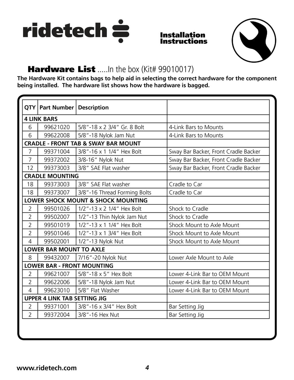
Hardware List...In the box (Kit# )
") Part # 33799-963-97 C0 Rear StrongArms Recommended Tools 963-97 C-0 Rear StrongArms Table of contents Page... Included components Page 3... Hardware List and Getting Started Page 4... Disassembly and Front
Part # 33799-963-97 C0 Rear StrongArms Recommended Tools 963-97 C-0 Rear StrongArms Table of contents Page... Included components Page 3... Hardware List and Getting Started Page 4... Disassembly and Front
Detroit Speed, Inc. Detroit Speed Control Arm and Spindle Kit A-Body P/N: &
 Detroit Speed, Inc. Detroit Speed Control Arm and Spindle Kit 1964-72 A-Body P/N: 030104 & 030105 The Detroit Speed A-Body front suspension kit is a bolt-on package that addresses the shortcomings of the
Global West Suspension 655 South Lincoln Ave San Bernardino Ca Phone Fax Web address globalwest.
 Global West Suspension 655 South Lincoln Ave San Bernardino Ca. 92408 Phone 877-470-2975 Fax 909-890-0703 Web address globalwest.net Mustang coilover instruction sheets for 64-66 Kit includes the following
INSTRUCTION S G-Comp Front Suspension: Chevy Camaro Speedway Motors, Inc Kit Contents:
 INSTRUCTION S 350-500 G-Comp Front Suspension: 70-81 Chevy Camaro Speedway Motors, Inc. 2017 Kit Contents: 350500.1 G-Comp Subframe, Camaro 350500.2 G-Comp Sway Bar Kit, Camaro 350500.3 Hardware Kit, G-Comp
INSTRUCTION S G-Comp Front Suspension: Chevy Nova Speedway Motors, Inc. 2017
 INSTRUCTION S 350-100 G-Comp Front Suspension: 62-67 Chevy Nova Speedway Motors, Inc. 2017 Kit Contents: 91035700 G-Comp Bare Subframe 350101 G-Comp Support Tubes 91035702 G-Comp Front Subframe Hardware
Part # Galaxie Air Suspension System
 350 S. St. Charles St. Jasper, In. 47546 Ph. 812.482.2932 Fax 812.634.6632 www.ridetech.com Part # 12160298 60-64 Galaxie Air Suspension System Front Components: 1 12162401 Master Series Single Adjustable
Chevy Nova Pro-Touring Front Suspension Installation Instructions
 1962-1967 Chevy Nova Pro-Touring Front Suspension Installation Instructions 1-800-984-6259 www.totalcostinvolved.com 1 Pro-Touring Clip A-Arm Assembly Sway Bar Assembly Fender Panel Kit 8 7/16-20 * 1 ¼
Installation Instructions Mustang Air Suspension. Part # Mustang Air Suspension System.
 Part # 12120298-1979-1989 Mustang Air Suspension System Recommended Tools Front Components: 12122401 Front ShockWave Strut Rear Components: 12125401 RearShockWave 12125899 Rear Lower StrongArms 12126699
USE THE PARTS LIST BELOW TO MAKE SURE YOUR KIT IS COMPLETE BEFORE INSTALLATION. IF ANY PIECES ARE MISSING, PLEASE CONTACT:
 1962-1967 Chevy Nova Pro-Touring Front Suspension Installation Instructions Tech line: 1-855-693-1259 www.totalcostinvolved.com Read and understand these instructions before starting any work! USE THE
RHINO SUSPENSION SYSTEM INSTALLATION INSTRUCTIONS
 PARTS INCLUDED: 2 FRONT UPPER A-ARMS 2 FRONT LOWER A-ARMS 2 UNI-BALL JOINTS 2 UNI-BALL JOINT STUDS 2 UNI-BALL JOINT CAPS 2 RETAINING RINGS 1 FRONT SHOCK ASSEM. 2 DELRON STEERING STOPS 2 SHOCK MOUNT SPACERS
INSTALLATION GUIDE Bolt-On Drag-Race Strut Clip Chevy II
 INSTALLATION GUIDE 7702 Bolt-On Drag-Race Strut Clip 1962-67 Chevy II Description: STRUT CLIP 4130 BOLT ON 62-67 CHEVY II, INCLUDES 4130 ROUND TUBE FRAME CLIP, DOUBLE-ADJUSTABLE STRUTS, ADJUSTABLE-HEIGHT
First, check and record the camber and caster readings, they will be adjusted later.
 First, check and record the camber and caster readings, they will be adjusted later. The caliper-mounting bosses are machined perpendicular to the spindle so they are an excellent place for the level.
Chrysler A-Body Tubular A-Arms Installation Instructions A-ARM INSTALLATION
 1967-1976 Dodge Demon 1112 67-72 Chrysler A-Body Tubular A-Arms Installation Instructions Thank you for your purchase of this Hotchkis Performance product. Your A-Arm set was designed with the performance
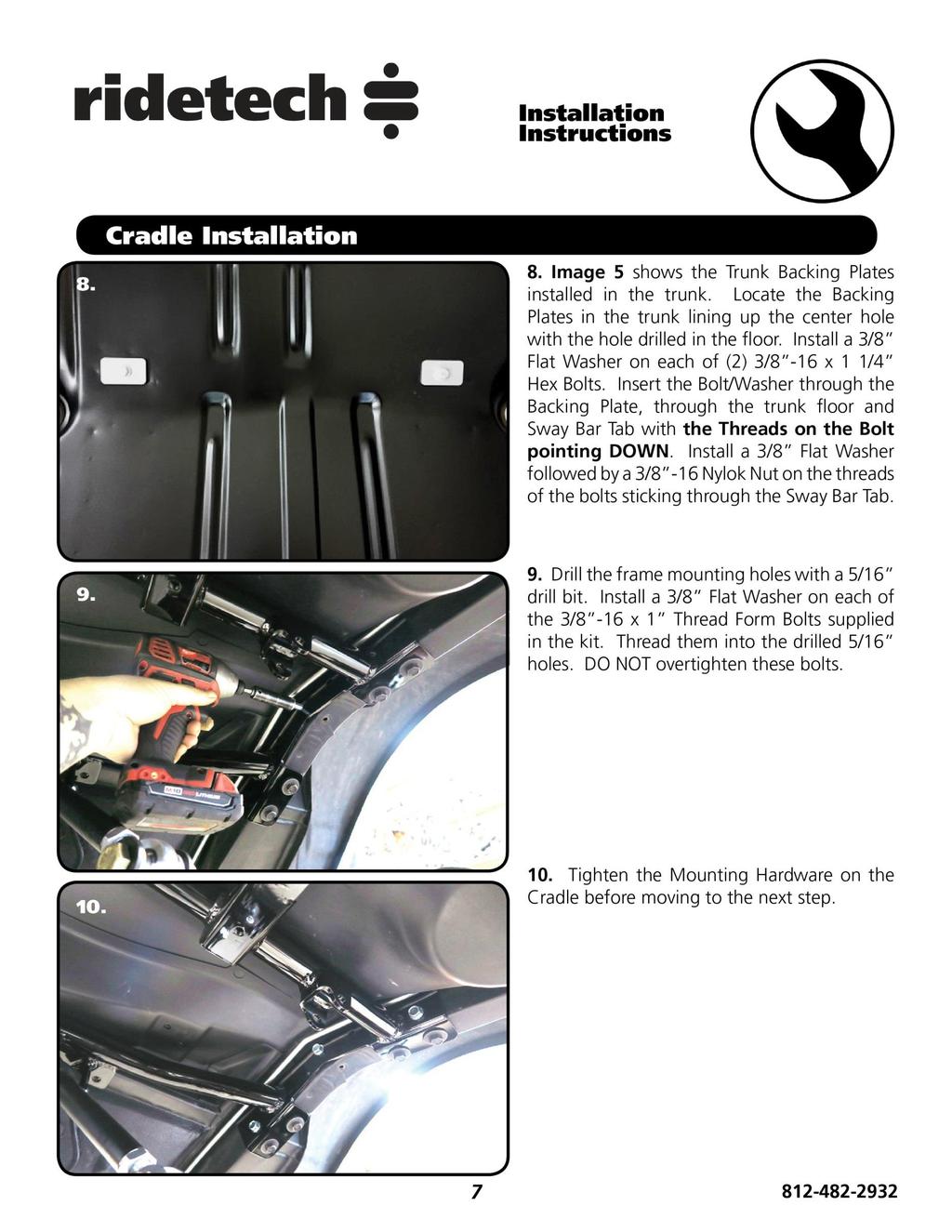
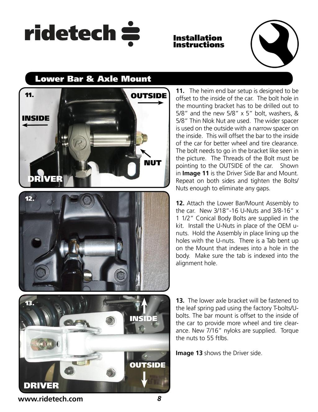
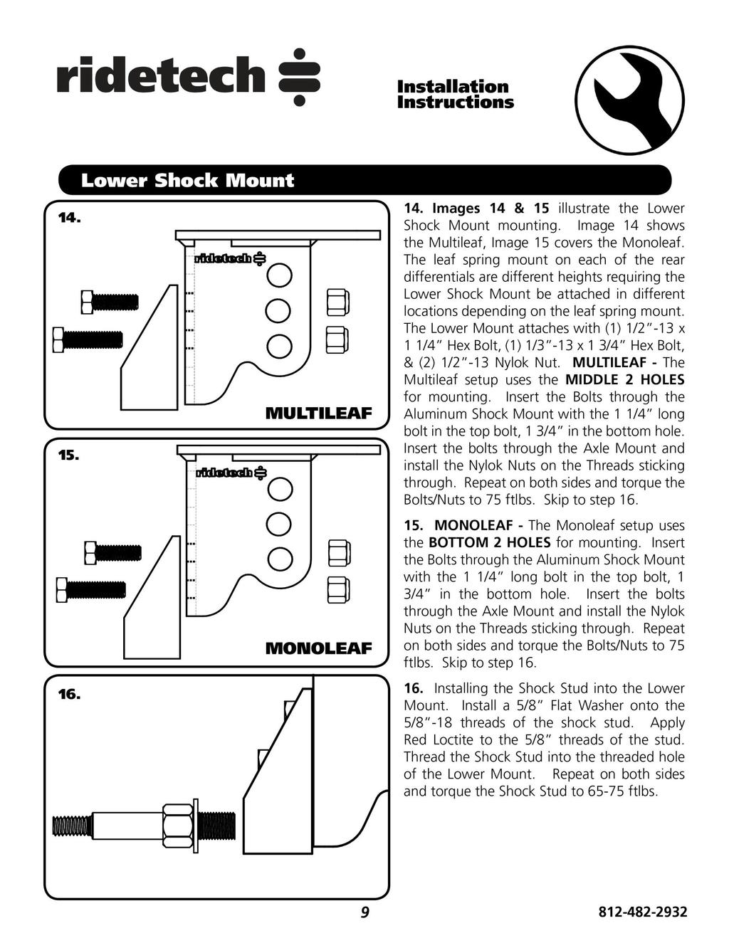
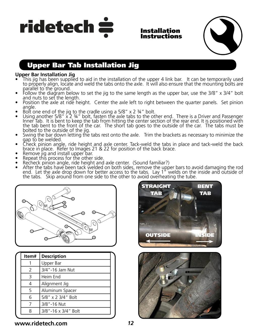
Part # GM F Body Rear R-Joint Bolt-in 4 Link GM F Body Rear Bolt-in 4Link. Table of contents. Installation Instructions
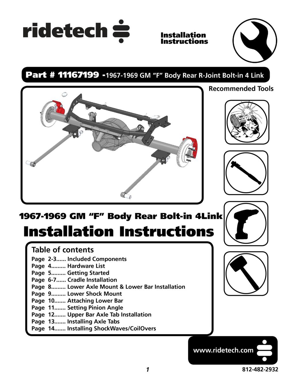
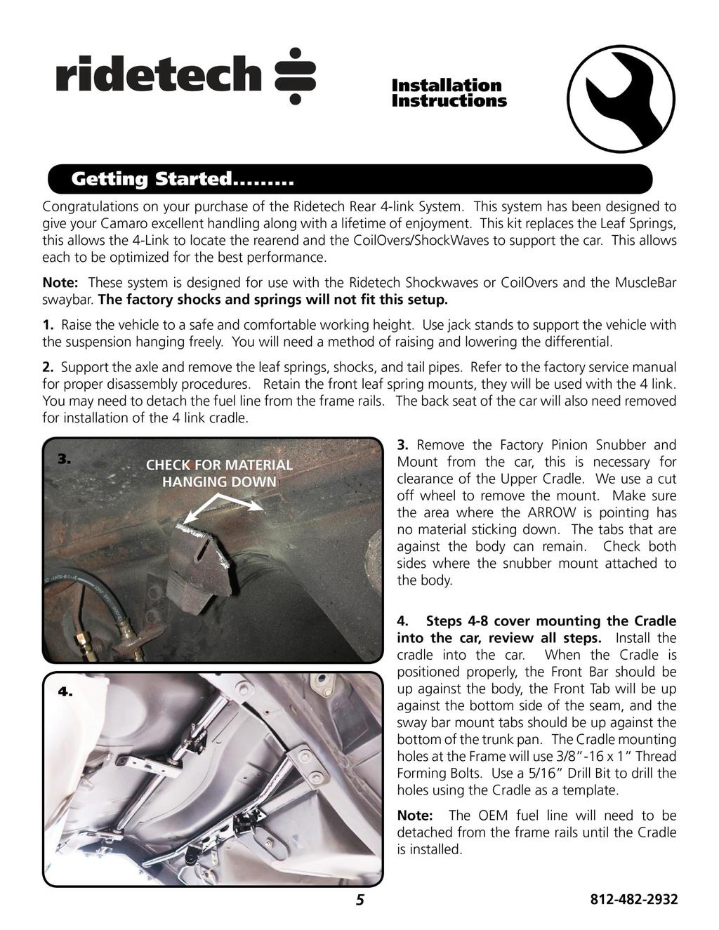
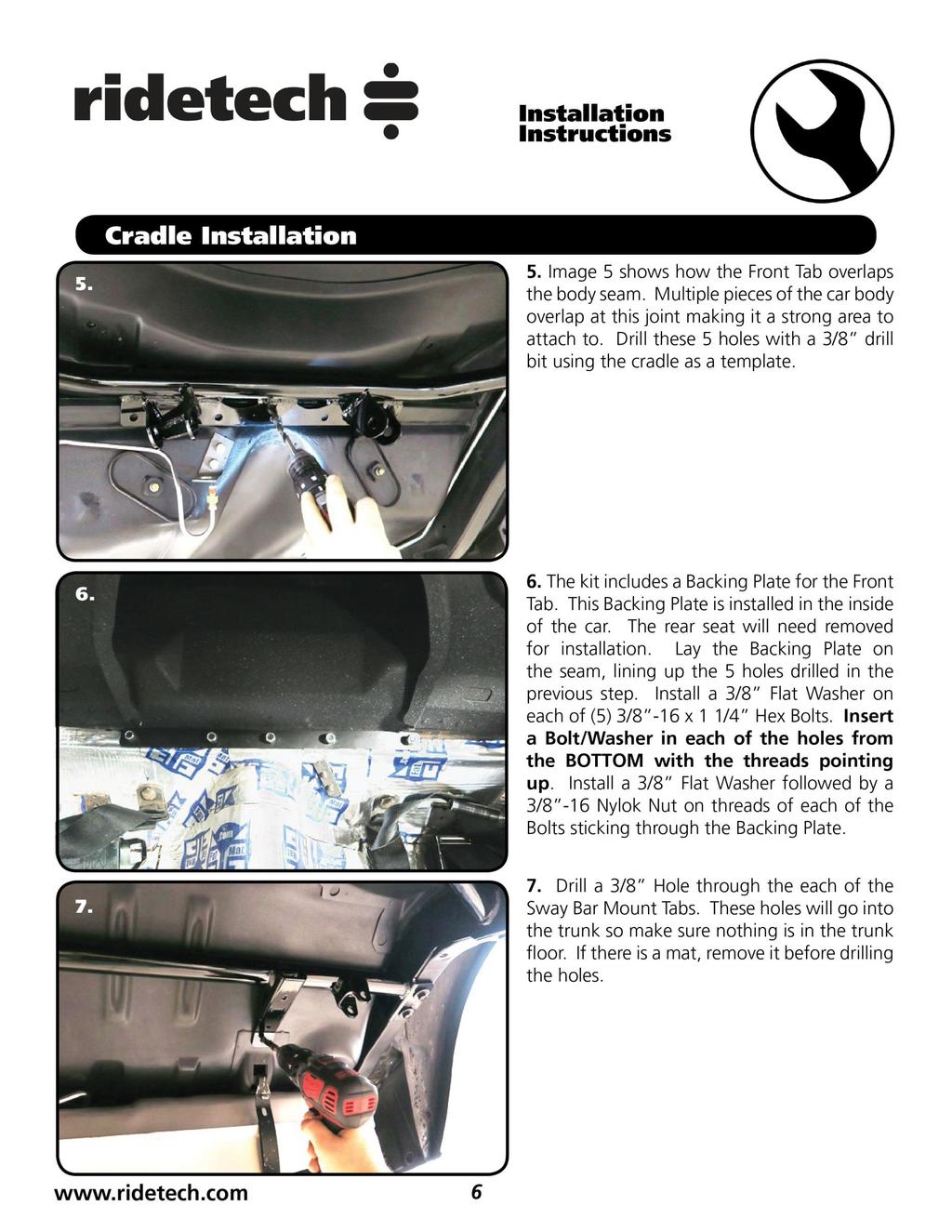
 Part # 11167199-1967-1969 GM F Body Rear R-Joint Bolt-in 4 Link Recommended Tools 1967-1969 GM F Body Rear Bolt-in 4Link Installation Table of contents Page 2-3... Included Components Page 4... Hardware
C-10 Rear 4Link
 Part # 11367199-1973-1987 C10 Rear 4Link Recommended Tools 1973-1987 C-10 Rear 4Link Installation Table of contents Page 2... Included Components Page 3... Hardware List & Getting Started Page 4... Disassembly
Installation Instructions Camaro Rear StrongArms. Part # Camaro Rear StrongArm Kit.
 Part # 11505899-2010-2015 Camaro Rear StrongArm Kit Recommended Tools 2010-2015 Camaro Rear StrongArms Installation Table of contents Pages 2-4... Included Components Page 5... Locking Plate and Camber
1969 Camaro. Concourse Style Disc Brake Conversion Kit Instllation Instructions
 Concourse Style Disc Brake Conversion Kit Instllation Instructions 1969 Camaro (1970 Chevelle Kit Shown) This document contains our regular disc brake conversion instructions with the addition of GM assembly
Commander SUSPENSION SYSTEM INSTALLATION INSTRUCTIONS
 PARTS INCLUDED: 2 - FRONT UPPER A-ARMS 2 - FRONT LOWER A-ARMS 4 - COTTER PINS 2-12MM JAM NUTS 2 - TIE ROD EXTENDERS 8- FLANGED DELRON BUSHINGS 4- DELRON CASTER SPACERS 6 - GREASE FITTINGS 3 - BEARING REMOVAL
Note: The transmission mount just happened to be upside down in this picture. (c) 2015 Total Cost Involved Engineering, Inc. All Rights Reserved.
 2015 Total Cost Involved Engineering, Inc. All Rights Reserved.") 1970-1981 Chevy Camaro & Pontiac Firebird Custom IFS Installation Instructions 1-855-693-1259 www.totalcostinvolved.com CHECK ALL PARTS INCLUDED IN THIS KIT TO THE PARTS LIST BEFORE INSTALLATION. IF ANY
1970-1981 Chevy Camaro & Pontiac Firebird Custom IFS Installation Instructions 1-855-693-1259 www.totalcostinvolved.com CHECK ALL PARTS INCLUDED IN THIS KIT TO THE PARTS LIST BEFORE INSTALLATION. IF ANY
Complete Front End Suspension Rebuild, Ñ Part 1, Tear Down
 Complete Front End Suspension Rebuild, 1955-57Ñ Part 1, Tear Down by Randy Irwin There is much more to performance than pure horsepower. Great performance comes from control and Classic Chevy InternationalÕs
Next, set the bar level and tighten it down. Do this on both the driver and passenger sides.
 Next, set the bar level and tighten it down. Do this on both the driver and passenger sides. Using two tape measures, measure the outside width at the front and the rear of the tubes. The front dimension
Detroit Speed, Inc. ALUMA-Frame Front Suspension System Ford Mustang P/N:
 Detroit Speed, Inc. ALUMA-Frame Front Suspension System 1964.5-1970 Ford Mustang P/N: 032050 INTRODUCTION All aluminum front suspension system for 1964.5-1970 Mustangs featuring DSE s unique suspension
Part # Mustang Rear AirBar
 350 S. St. Charles St. Jasper, In. 47546 Ph. 812.482.2932 Fax 812.634.6632 www.ridetech.com Part # 12087199 64-70 Mustang Rear AirBar Components: 1 90000513 Lower Shockwave mount 1 90000514 Lower Shockwave
INSTALLATION GUIDE. TCP TIER-14 Bump Steer Conversion Kit - Early Mustang to Late Spindle
 READ ALL INSTRUCTIONS COMPLETELY AND THOROUGHLY UNDERSTAND THEM BEFORE DOING ANYTHING. CALL TOTAL CONTROL PRODUCTS TECH SUPPORT (916) 388-0288 IF YOU NEED ASSISTANCE. INSTALLATION GUIDE TCP TIER-14 Bump
A/F/X Body GM Installation Instructions
 A/F/X Body GM Installation Instructions Power Disc Conversion 64-72 A Body / 67-69 F Body / 68-74 X Body 9 slimline booster pictured Your new disc brake conversion kit can be bolted up with standard hand
USE THE PARTS LIST BELOW TO MAKE SURE YOUR KIT IS COMPLETE BEFORE INSTALLATION. IF ANY PIECES ARE MISSING, PLEASE CONTACT:
 55-59 Chevy Truck Chassis Custom IFS & 4-Link Install Instructions Tech line: 1-855-693-1259 www.totalcostinvolved.com Read and understand these instructions before starting any work! USE THE PARTS LIST
55-64 Full Size Chevy
 55-64 Full Size Chevy Installation Instructions Power Disc Conversion 9 slimline booster pictured Your new disc brake conversion kit can be bolted up with standard hand tools. The only tools you may not
Installation Notes: #86000-R Race Series +3.5 L/T Kit
 159 North Maple St. Unit J, CORONA CA 92880 P. 951-737-9682 F. 951-737-9006 WWW.CHAOSFAB.COM Installation Notes: #86000-R Race Series +3.5 L/T Kit Factory manual is recommended for removal and re-installation
Installation Instructions
 Part # 50098-00 Up Camaro Air System Front Components: 300 Front ShockWave Strut Rear Components: 5050 Rear ShockWave Recommended Tools 00 up Camaro Air System Table of contents Pages -9... Front ShockWave
'99-03 CHEVROLET/GMC IFS 4WD 6" SUSPENSION SYSTEM P/N INSTALLATION INSTRUCTIONS
 1/16/04 '99-03 CHEVROLET/GMC IFS 4WD 6" SUSPENSION SYSTEM P/N. 10-41099 INSTALLATION INSTRUCTIONS NOTE: Each Lift Kit and options to Lift Kits are packaged separately. Therefore, installation procedures
INSTALLATION INSTRUCTION 88094
 INSTALLATION INSTRUCTION 88094 FOR RANCHO SUSPENSION SYSTEM RS6594B 4WD & 2WD NISSAN TITAN READ ALL INSTRUCTIONS THOROUGHLY FROM START TO FINISH BEFORE BEGINNING INSTALLATION Rev D IMPORTANT NOTES! WARNING:
Installing the Custom IFS
 35-40 Ford Car & 35-41 Ford Truck Chassis Custom IFS & 4-Link Install Instructions Tech Line: 1-855-693-1259 www.totalcostinvolved.com Read and understand these instructions before starting any work! USE
Slide the billet aluminum cap over the bushing and secure with the 3/8-16 x 2 1/2 socket head allen and locknuts provided.
 Slide the billet aluminum cap over the bushing and secure with the 3/8-16 x 2 1/2 socket head allen and locknuts provided. Put the urethane bushings into the upper antiroll-bar-link eyebolt. Coat the bushings
Installation Instructions
 Part # 12087199-1965-1970 Mustang Rear Bolt-in 4 Link Recommended Tools 1965-1970 Mustang Rear Bolt-in 4 Link Installation Table of contents Page 2... Included components Page 3... Hardware List and Getting
Installing the Custom IFS Installing the lower control arms:
 33-34 Ford Car & Truck Chassis Custom IFS & 4-Link Install Instructions Tech Line: 1-855-693-1259 www.totalcostinvolved.com Read and understand these instructions before starting any work! USE THE PARTS
Suspension System RS6582B
 Suspension System RS6582B Tahoe/Yukon READ ALL INSTRUCTIONS THOROUGHLY FROM START TO FINISH BEFORE BEGINNING INSTALLATION IMPORTANT NOTES! WARNING: This suspension system will enhance the off-road performance
PPM-8022 / PPM-8042 JEEP JK STAGE 2 SYNERGY SUSPENSION SYSTEM Version 1
 POLY PERFORMANCE MFG. 870 INDUSTRIAL WAY, SAN LUIS OBISPO, CA (805) 242-0397 PPM-8022 / PPM-8042 JEEP JK STAGE 2 SYNERGY SUSPENSION SYSTEM Version 1 GENERAL NOTES: These instructions are also available
Mustang. MOD1 Coilover Kit FXXADK0100, FXXADK0200, FXXADK0400 FXXA1K0100, FXXA1K0200, FXXA1K0400
 1964.5-1973 Mustang MOD1 Coilover Kit FXXADK0100, FXXADK0200, FXXADK0400 FXXA1K0100, FXXA1K0200, FXXA1K0400 2276 Research Dr. Livermore, Ca 94550 Ph: (925)-443-6300 E: maier@mikemaierinc.com Page 1 of