Part # Mustang Coil-Over System
|
|
|
- Everett Ernest Harper
- 6 years ago
- Views:
Transcription
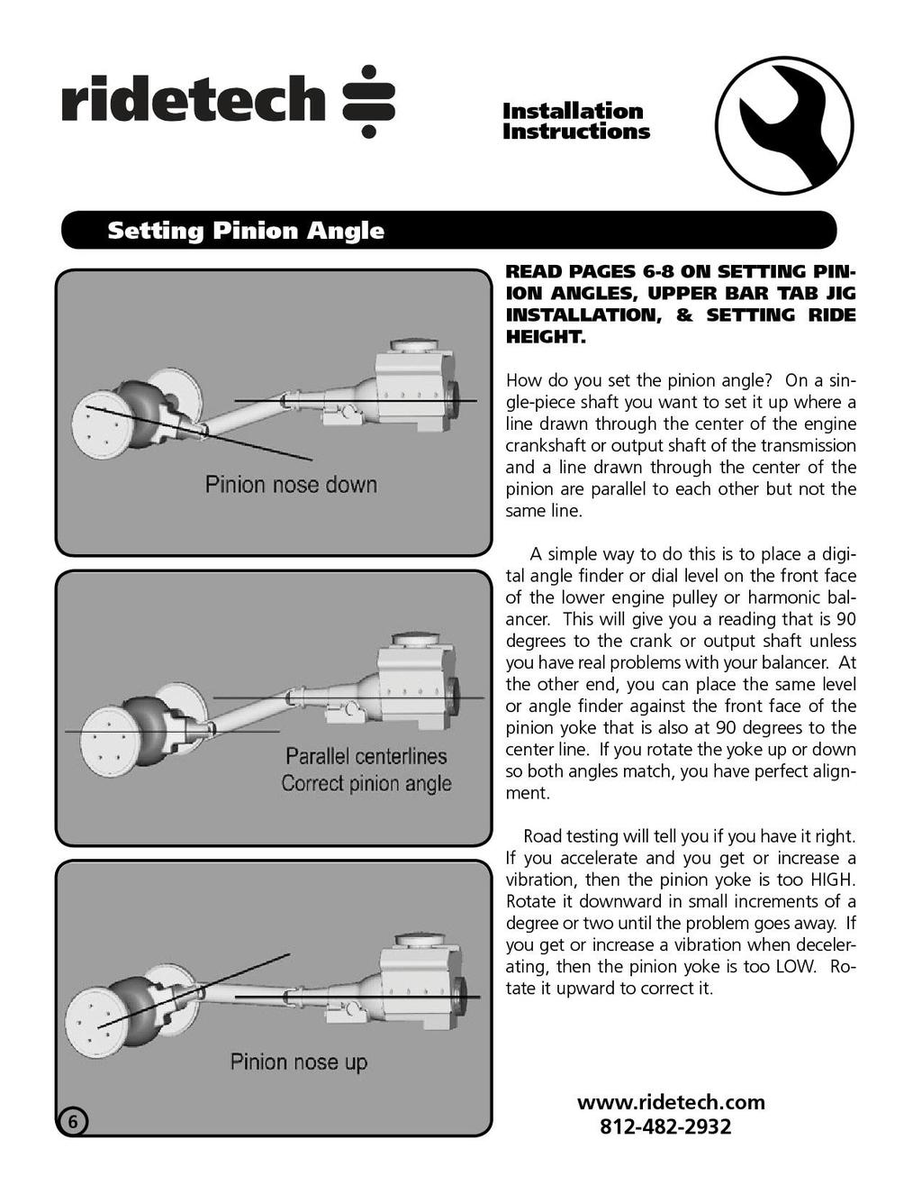
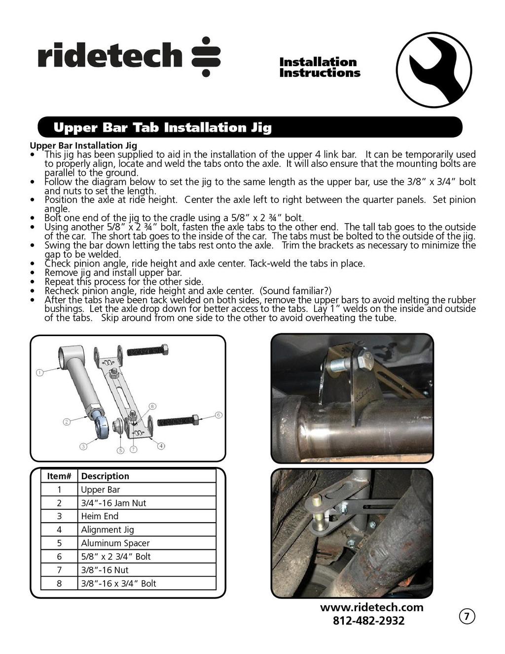
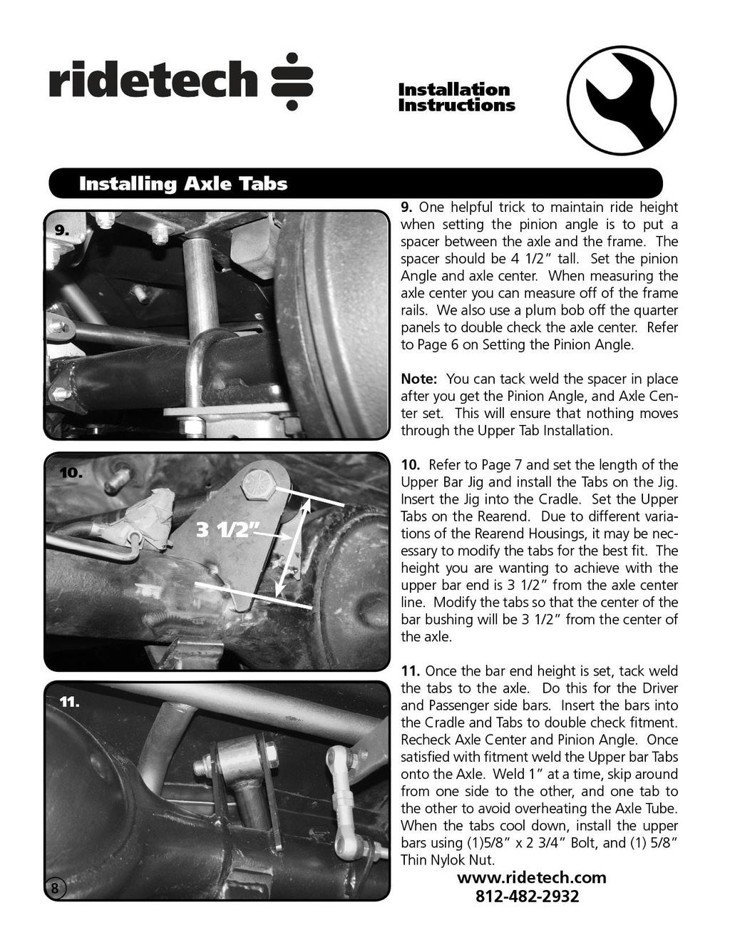
1 350 S. St. Charles St. Jasper, In Ph Fax Front Components: HQ Series Front Coil-Overs Part # Mustang Coil-Over System Front Tru-Turn Suspension Package Front MuscleBar Rear Components: HQ Series Rear Coil-Overs Bolt-on 4 Link Components: Spanner Wrench
2 350 S. St. Charles St. Jasper, In Ph Fax Shock Assembly: Part # Mustang Front HQ Series Coil-Overs For Use w/ Strong Arms Stroke HQ Series shock I.D. bearing Bearing snap ring Short Delrin stud top 2 Components: Coil spring 8 long / 650 # rate stud top base Spring retainer kit includes upper and lower spring retainer Aluminum cap for Delrin ball Delrin ball upper half Delrin ball lower half Upper Shockwave mount Aluminum Upper plate Hardware: /16 SAE Nylok jam nut Stud top hardware /16 x 1 USS Flange bolts Upper mount to strut tower
 8. Screw 9. Snap ring")
3 1. Impact Forged, Monotube shock 2. Rebound adjustment knob (SA Only) 3. Upper coil spring retainer 4. Lower coil spring retainer 5. High tensile coil spring 6. Set screw 1. Stud top base 2. Lower Delrin ball half 3. Upper Delrin ball half 4. Aluminum cap 5. 9/16 Nylok jam nut 6. Threaded stud 7. Adjustment knob (SA Only) 8. Screw 9. Snap ring

 3.")
4 1. Place the upper plate on top of the strut tower. While holding the upper Shockwave mount up to the bottom of the strut tower, fasten the assembly with three 5/16 x 1 flange bolts. 2. Place the stud up through the upper mount. (See diagram) 3. Attach the bottom of the shock to the upper arm w/ the hardware supplied w/ the kit.
5 Ride Height We have designed most cars to have a ride height of about 2 lower than factory. To achieve the best ride quality & handling, the shock absorber needs to be at 40-60% overall travel when the car is at ride height. This will ensure that the shock will not bottom out or top out over even the largest bumps. Measuring the shock can be difficult, especially on some front suspensions. Measuring overall wheel travel is just as effective and can be much easier. Most cars will have 4-6 of overall wheel travel. One easy way to determine where you are at in wheel travel is to take a measurement from the fender lip (center of the wheel) to the ground. Then lift the car by the frame until the wheel is just touching the ground, re-measure. This will indicate how far you are from full extension of the shock. A minimum of 1.5 of extension travel (at the wheel) is needed to ensure that the shock does not top out. If you are more than 3 from full extension of the shock then you are in danger of bottoming out the shock absorber. Adjusting Spring Height When assembling the CoilOver, screw the spring retainer tight up to the spring (0 preload). After entire weight of car is on the wheels, jounce the suspension and roll the car forward and backward to alleviate suspension bind. If the car is too high w/ 0 preload then a smaller rate spring is required. Although threading the spring retainer down would lower the car, this could allow the spring to fall out of its seat when lifting the car by the frame. If the car is too low w/ 0 preload, then preload can then be added by threading the spring retainer up to achieve ride height. On stroke shocks, up to 1.5 of preload is acceptable. On 5-7 stroke shocks, up to 2.5 of preload is acceptable. If more preload is needed to achieve ride height a stiffer spring rate is required. Too much preload may lead to coil bind, causing ride quality to suffer.

6 350 S. St. Charles St. Jasper, In Ph Fax Part # Mustang Tru-Turn Suspension Package Front Components: Upper Strong Arms Lower Strong Arms Tru Turn System
7 350 S. St. Charles St. Jasper, In Ph Fax Part # Mustang Upper StrongArms For Use w/ Shockwaves or CoilOvers Must be Used with Ridetech Tru-Turn Setup Components: Driver Upper StrongArm Pass Upper StrongArm Upper ball joint Ball joint spacer Billet Aluminum drop cross shaft Heim ends ¾ -16 thread x 5/8 I.D Alignment shim I.D. Bearing spacer Hardware: /16-18 x 1 ¼ Hex Bolt Upper Ball joint /16-18 Nylok Nut Upper Ball joint /16 SAE Flat washer Upper Ball joint /8-18 x 1 ¾ Gr.8 bolt Rod end to cross shaft ½ -13 x 2 ½ Gr.5 bolt Cross shaft to body/shock to upper arm ½ -13 nut Cross shaft to body ½ SAE flat washer Cross shaft to body ½ lock washer Cross shaft to body ½ -13 Nylok nut Shockwave/CoilOver to upper arm ¾ -16 jam nut Heim ends

8 Item # Description Qty. 1. Control arm 1 2. Heim ends ¾ -16 thread x 5/8 I.D Alignment shim /8-18 x 1 ¾ Gr.8 bolt /8 lock washer 2 6. ½ SAE flat washer /8 SAE flat washer 2 8. ½ -13 x 2 ½ Gr.5 bolt Cross shaft ½ -13 Nut ½ -13 Nylok Nut ½ -13 x 2 ½ Gr.5 bolt Ball Joint Spacer /16 flat washer /16-18 x 1 ¼ bolt /16-18 Nylok Nut 3
 5/16-18 x 1 ¼ Bolts, (3) 5/16-18 Nylok Nuts and (6) 5/16 SAE Flat Washers. Do this for both Control Arms. Refer to the Diagram on Page 3. 2.")

9 1. Bolt the Ball Joint to the Control Arm with the BALL JOINT SPACER between the Ball Joint and Control Arm. The Ball Joints/Spacers are attached using (3) 5/16-18 x 1 ¼ Bolts, (3) 5/16-18 Nylok Nuts and (6) 5/16 SAE Flat Washers. Do this for both Control Arms. Refer to the Diagram on Page Bolt the upper StrongArm to the body using ½ x 2 ½ bolts, flat washers and lock washers. The ARROW points to the front of the vehicle. A shim is supplied and may need to be installed between the body and the arms to achieve proper alignment. 3. The arms are preset at the factory so the alignment should be close, but the vehicle must be aligned before driving. Note: The upper arm mounting holes on many cars have been redrilled 1 lower. This is done to improve the handling. Our cross shaft has the drop built into it; make sure to use the factory mounting holes. 4. Bolt the upper arm to the spindle using the hardware and cotter pin supplied. 5. Attach the Shockwave to the upper StrongArm using a ½ x 2 ½ bolt and Nylok nut. 6. This control arm is designed to work with our MuscleBar sway bar. The end link will attach to the front mounting tab on the upper arm.
10 350 S. St. Charles St. Jasper, In Ph Fax Part # Mustang Lower StrongArms To Be Used With Ridetech TRU-TURN Components: Driver side lower arm Passengers side lower arm Lower ball joint Kevlar lined heim end Rod End Spacers Control arm pivot bearing Bearing housing Bearing retaining plate Aluminum bearing spacer Bearing stud (Set to 2-7/8 ) Hardware: ½ -13 x 3 ¼ Gr.5 bolt Lower arm to frame ½ -13 Nylok nut Lower arm to frame /16-18 x 1 ½ Hex Bearing housing /16 lock washer Bearing housing ¾ -16 Jam nut Stud to arm ¾ -16 Lock nut Stud to bearing ¾ x 2 flat washer Stud to bearing


11 Installation Instructions 1. Raise and support vehicle at a safe, comfortable working height. Let the front suspension hang freely. 2. Remove the coil spring, shock absorber, upper shock bracket, strut rod, sway bar, upper and lower control arms. Refer to factory service manual for proper disassembly procedure. 3. Be sure to remove the outer bushing sleeve from the strut rod frame mount. 4. Remove any excess undercoating or rust. 5. Using the bushing retainer as a template, mark the holes to drill with a center punch. 6. Remove the retainer and drill the holes with a 3/8 bit. 7. Place the bearing inside the bearing housing, then clamp it to the frame with the bearing retainer and the 5/16 x 1 ½ SHCS and lock washers. Front


12 8. The bearing stud should already be threaded into the lower arm, factory set at 2-7/8 (measuring from the end of the arm to the bearing). 9. Slide the stud through the bearing, then slide the aluminum spacer over the stud with the larger end toward the front of the car. Secure the assembly with a ¾ Nylok Nut and flat washer. Note: The caster setting should set at around 4.0 degrees positive. Vehicle must be aligned before driving. 10. Install the 2 aluminum spacers into the rod end that goes into the factory control arm pivot. 11. Attach the other end of the lower control arm to the factory frame mount using a ½ x 3 ¼ bolt and Hex nut. 12. Slide the ball joint boot over the ball joint, then place the spindle over the ball joint stud. A ball joint spacer will be necessary to align the castle nut with the cotter pin hole. Grease ball joint Note: Before installing the spindle, turn the ball joint stud so that the cotter pin hole faces front to back. This will make it easier to install/remove the cotter pin.
13 Item # Description Qty. 1. Driver side arm 1 2. Kevlar lined Heim End 1 3. Control Arm pivot bearing 1 4. Bearing retaining plate 1 5. Bearing stud (Set to 2-7/8 ) 1 6. Ball Joint 1 7. Heim end spacer 2 8. Bearing Housing /16 Lock washer /16-1 ½ Gr5 bolt Aluminum bearing spacer ¾ -16 Lock nut ½ -13 x 3 ¼ Gr.5 bolt ½ -13 Nylok nut ¾ -16 Jam Nut ¾ X 2 Flat washer 1

14 350 S. St. Charles St. Jasper, In Ph Fax Part # Mustang TruTurn System Item # Part # Description-Torque Specification Qty Drag link bracket LH Thread Heim End /8-18 LH jam nut /8-18 RH jam nut Heim end Large stud tie rod Inner tie rod stud Drag link stud Tie rod adjuster Driver steering arm Pass steering arm RideTech spindle 1 pr ½ -20 Lock nut-50 ft lbs /16-20 castle nut-35 ft lbs /32 Cotter pin /8-18 Thin top lock nut Driver steering stop Pass steering stop ½ -13 Nylok Nut ½ -13 x 1 ¼ Hex Head Bolt /8-18 Mechanical lock nut /16 Flatwasher 6
15 350 S. St. Charles Street Jasper, In THIS SYSTEM WILL ONLY WORK WITH RIDETECH STRONG ARMS Installation instructions This kit can be used with the OEM draglink or Borgeson Power Steering Conversion Kit 1. You should be using Ridetech Strong Arms and already have installed them. 2. Assemble the new RideTech draglink adapter bracket onto the OEM draglink with the supplied tapered studs and washers per the enclosed drawings. 3. Install the new RideTech spindles onto the control arms per the enclosed drawings. Ball joint nut torque = 83 ft lbs 4. Install the Steering arm and Steering Stop at the same time. The nuts should be on the frame side of the spindle. 5. Install the remainder of the Tru Turn steering linkage as shown in the attached drawings. MAKE SURE that ALL cotter pins are used in the appropriate places and that there is no binding or interference throughout the entire suspension travel. 6. Adjust the camber and toe roughly until you can get the vehicle to a proper alignment shop. The recommended alignment settings are: Camber to -1.5 [within.3 from side to side] Caster 4 to 7 degrees positive [run.5 degrees more on pass side to allow for road crown] Toe - 1/8 to ¼ toe in Feel free to experiment with alternative alignment settings that may be more appropriate for your particular driving style. Installation notes: A. The draglink bracket has one attachment hole [A] that is slotted. This is to accommodate the variations in manufacturing and machining processes, as well as any wear that may have occurred to the original draglink since that time. B. RideTech has successfully fitted a Baer disc brake system to this spindle. Other brands of disc brake brackets MAY need clearancing or adjustment for proper installation. The RideTech spindle duplicates the GM A body and F body bolt pattern for brake bracket installation. You will need 5 on 4.5 bolt pattern to keep it the same as the factory rear. C. MAKE SURE that the cotter pins are properly installed in all appropriate places [C] to ensure that the castle nuts do not become loose and fail. These are VERY important connections! D. IF your oem drag link is severely worn at the inner tie rod attachment holes [D] you may need to replace that unit with a new oem style draglink to ensure that the [RideTech supplied] tapered pin adapters DO NOT pull through that hole.


16 350 S. St. Charles St. Jasper, In Ph Fax Note: Due to variances in the thickness of the factory drag link, 7/16 flat washers are provided and may be needed to align the castle nut with the cotter pin hole. 2. The studs with the long hex on them will get installed into the factory draglink with the taper going into the draglink, a 7/16 castle nut is used to attach it to the draglink. Torque the nuts to 35 ft lbs and tighten as needed to align cotter pin hole and install cotter pin. The straight shank will point to the front of the car. Note: It may be necessary to install 7/16 washers under the castle nut to get the cotter pin engaged properly.


17 3. Install the Ridetech spindle on the control arms. 4. Install the steering arms and steering stops onto the spindle. The steering arms angles toward the draglink. The steering stops are marked D and P. The steering arm is attached to the spindle using ½ -20 x 2 ½ Flat Socket Cap Bolts and Nylok nuts. The upper tab of the steering stop is attached to the spindle using ½ -13 x 1 ¼ Hex head bolt and Nylok. 5. Install the stud with the round flange into the steering arm with the taper going into the steering arm. Torque the nuts to 35 ft lbs and tighten as needed to align cotter pin hole and install cotter pin. 6. The studs with the short hex get installed into the draglink adapter. The short side goes into the adapter attached with the 5/8-18 thin top lock nut, with the long side of the stud pointing forward.


18 7. The tie rod can now be assembled to a center to center length of 14 ¼ to start with having equal amount of threads on both ends. These Aluminum adjusters have a left hand thread on one end and a right hand thread on the other. You should use antiseize when threading the heim ends into the adjuster. 8. Install the tie rod assembly onto the studs using the 5/8-18 lock nuts. Note: If using a factory style stamped caliper bracket, the bracket may need to be trimmed. The dust shield may also need to be modified.
19 350 S. St. Charles St. Jasper, In Ph Fax Brake Kits The Mustang TruTurn Suspension package uses a GM Spindle used on F body, A body, and X body. Any brake kit designed for this spindle will work it just needs a 4 ½ on 5 bolt pattern to keep the same bolt pattern as the rear of the Mustang. We had worked with Baer and Wilwood to put together brake kits for our suspension. Both companies have brake kits that will work with your car, depending on wheel size and your braking needs. We have listed the basic brake kit and each company offers options for their brake kits. Contact info: Baer- Phone: , Web- Wilwood- Phone: , Web- Baer Brake Kits: Minimum Baer Part Brake Kit Name Description Wheel Size # 15 and bigger SS4+ 4 piston caliper / 11 2 piece rotor (some 14 ) 16 and bigger T4 Pro 13 Pro+13 4 piston caliper / 13 1 piece rotor 6 piston caliper / 13 1 piece rotor 6 piston caliper / 13 2 piece rotor 17 and bigger Pro+14 Ext+14 6 piston caliper / 14 2 piece rotor 6 piston caliper / 14 2 piece rotor 18 and bigger Ext+15 6 piston caliper / 15 2 piece rotor Wilwood Brake Kits: Minimum Wilwood Brake Kit Name Description Wheel Size Part # 14 and bigger Dyna Pro Single 2 piston caliper / 10 2 piece rotor 15 and bigger and bigger and bigger Forged Dynalite Pro Forged Dynalite Dyna Pro 6 Forged Narrow Superlite 6R Forged Narrow Superlite 6R W6A Big Brake Forged Narrow Superlite 6R 4 piston caliper / 11 2 piece rotor 4 piston caliper / piece rotor 6 piston caliper / 12/19 2 piece rotor 6 piston caliper / piece rotor 6 piston caliper / piece rotor 6 piston caliper / 14 2 piece rotor 6 piston caliper / 14 2 piece rotor As with any brake kit you need to check the template to see if it will clear your wheels. These templates can be obtained by going to the brake manufactures web sites listed above.
 2 Frame bushing 2 Frame bracket 2 90002342 PosiLink spacer 2 90000103 PosiLink adapter 4 90000926 10mm")
20 350 S. St. Charles St. Jasper, In Ph Fax Part # Mustang Front MuscleBar Sway Bar (Includes the following) 2 Frame bushing 2 Frame bracket PosiLink spacer PosiLink adapter mm 90 degree PosiLink Tube of lithium grease Hardware: /8 x 1 USS bolt Frame bracket /8 USS Nylok nut Frame bracket /8 SAE flat washer Frame bracket/posilink mm x 1.5 Nylok nut PosiLink mm x 1.5 x 75mm (3 ) stud (use Loctite) /8-18 Jam Nylok Posilink adapter /8 Star washer Posilink adapter


21 Installation Instructions *****This sway bar is designed to work with our upper StrongArms****** 1. Apply lubricant to the poly bushing, then slide it over the sway bar. 2. Place the sway bar fame bracket over the bushing. Bolt the sway bar to the frame using the 3/8 x 1 ¼ bolts, Nylok nut and flat washers supplied. Note: Do not tighten the frame bolts until after the PosiLinks are installed. 3. Attach the 90 degree end of the PosiLink to the front tab of the upper control arm using a 10mm Nylok nut and a 3/8 flat washer on each side of the tab. The nut will be towards the front of the car with the lower nut towards the frame. Drivers side shown in picture.


22 4. Install the PosiLink adapter on to the sway bar end. Install the star washer between the adapter and the sway bar with the Nylok on the bottom of the swaybar. 5. Install the Posilink into the adapter with the nut towards the frame of the car. 5. The frame bolts can now be tightened. 6. Check sway bar and PosiLink clearance through full suspension travel. 7. Ensure that the PosiLinks do not bind through full suspension travel. Pass side control arm shown in picture.
23
24
25
26
27
28
29
30
31
32 350 S. St. Charles St. Jasper, In Ph Fax Should I weld my AirBar 4 link assembly in? Since we get this question quite often, it deserves a proper explanation. The AirBar has been designed for bolt-in installation. We have paid special attention to interfacing with key structural areas of each vehicle, fastening bracketry in at least two planes to properly distribute load paths, and to using appropriate fasteners that roll, rather than cut, threads into the vehicle structure. Having said that, you could potentially encounter a vehicle that has rust or collision damage in these areas. Or maybe you intend to consistently place the vehicle in severe racing applications with sticky racing slicks and high speed corners. In these cases it is perfectly acceptable to weld the AirBar components into your vehicle. Even in these severe cases we recommend that you install the entire AirBar assembly first [including the fasteners], and then use short 1 long tack welds to secure your installation. Remember that the vehicle structure metal is typically much thinner [ ] than the.188 thick AirBar brackets. If you burn through the vehicle sheet metal structure you may end up with an installation that is weaker than before you tried to weld it. The other reason to weld in your AirBar assembly is you simply want to. You re a welding kind of guy that s the way you ve always done it you have the skills and equipment to do it. In that case weld away with our blessing!
33 350 S. St. Charles St. Jasper, In Ph Fax Part # Mustang HQ Series Rear Coil-Overs For Use w/ RideTech 4 Link Shock Assembly: stroke HQ Series shock eyelet Single Adjustable I.D. bearing Bearing snap ring Components: Coil spring 12 long / 150 # rate Spring retainer kit Aluminum spacer for bearings
34
Part # Mustang Complete HQ Series Coil-Over Kit
 350 S. St. Charles St. Jasper, In. 47546 Ph. 812.482.2932 Fax 812.634.6632 www.ridetech.com Front Components: Part # 12090210 64-66 Mustang Complete HQ Series Coil-Over Kit 1 12093509 HQ Series Front Coil-Overs
Part # Mustang Air Suspension System
 350 S. St. Charles St. Jasper, In. 47546 Ph. 812.482.2932 Fax 812.634.6632 www.ridetech.com Front Components: Part # 12090298 64-66 Mustang Air Suspension System 1 12093001 HQ Series Front Shockwaves 1
Part # Mustang Tru-Turn Suspension Package
 350 S. St. Charles St. Jasper, In. 47546 Ph. 812.482.2932 Fax 812.634.6632 www.ridetech.com Part # 12099599 64-66 Mustang Tru-Turn Suspension Package Front Components: 1 12093699 Upper Strong Arms 1 12092899
Part # Mustang Tru-Turn Suspension Package
 350 S. St. Charles St. Jasper, In. 47546 Ph. 812.482.2932 Fax 812.634.6632 www.ridetech.com Part # 12099599 64-66 Mustang Tru-Turn Suspension Package Front Components: 1 12093699 Upper Strong Arms 1 12092899
Part # Mustang Complete HQ Series Coil-Over Kit
 350 S. St. Charles St. Jasper, In. 47546 Ph. 812.482.2932 Fax 812.634.6632 www.ridetech.com Front Components: Part # 12090210 64-66 Mustang Complete HQ Series Coil-Over Kit 1 12093509 HQ Series Front Coil-Overs
Part # Cougar CoilOver System
 Front Components: 1 12103510 HQ Series Front CoilOvers 1 12102899 Lower StrongArms 1 12103699 Upper StrongArms 1 12109100 Front MuscleBar w/ PosiLinks 350 S. St. Charles St. Jasper, In. 47546 Ph. 812.482.2932
Part # Mustang Complete NA CoilOver Kit
 Front Components: 350 S. St. Charles St. Jasper, In. 47546 Ph. 812.482.2932 Fax 812.634.6632 www.ridetech.com Part # 12090109 64-66 Mustang Complete NA CoilOver Kit 1 12093509 Non Adjustable Front CoilOvers
Part # Mustang Complete SA CoilOver Kit
 Front Components: 350 S. St. Charles St. Jasper, In. 47546 Ph. 812.482.2932 Fax 812.634.6632 www.ridetech.com Part # 12100210 67-70 Mustang Complete SA CoilOver Kit 1 12103510 Single Adjustable Front CoilOvers
Part # Mustang Complete CoilOver Kit
 Front Components: 1 12103509 Front CoilOvers 1 12102899 Lower StrongArms 1 12103699 Upper StrongArms 350 S. St. Charles St. Jasper, In. 47546 Ph. 812.482.2932 Fax 812.634.6632 www.ridetech.com Part # 12100109
Part # Mustang Complete Level 2 Air Suspension Kit
 350 S. St. Charles St. Jasper, In. 47546 Ph. 812.482.2932 Fax 812.634.6632 www.ridetech.com Front Components: Part # 12090299 64-66 Mustang Complete Level 2 Air Suspension Kit 1 12093001 HQ Series Front
Part # GM F Body Complete CoilOver System
 350 S. St. Charles St. Jasper, In. 47546 Ph. 812.482.2932 Fax 812.634.6632 www.ridetech.com Part # 11170109 70-81 GM F Body Complete CoilOver System Front Components: 1 11173509 Front Fixed Valving CoilOvers
Part # Mustang Complete Level 3 Air Suspension Kit
 350 S. St. Charles St. Jasper, In. 47546 Ph. 812.482.2932 Fax 812.634.6632 www.ridetech.com Front Components: Part # 12090399 64-66 Mustang Complete Level 3 Air Suspension Kit 1 12093011 TQ Series Front
Part # Impala Fixed Valving Coil-Over Suspension Package
 350 S. St. Charles St. Jasper, In. 47546 Part # 11060109 59-64 Impala Fixed Valving Coil-Over Suspension Package Front Components: 1 11053509 RQ Series Front Coil-overs 1 11052899 Front Lower StrongArms
Part # Impala Level 1 Complete Coil-Over System RQ Series
 350 S. St. Charles St. Jasper, In. 47546 Ph. 812.482.2932 Fax 812.634.6632 www.ridetech.com Part # 11290109 65-66 Impala Level 1 Complete Coil-Over System RQ Series Front Components: 1 11283509 RQ Series
Part # Impala TQ CoilOver Suspension Package
 350 S. St. Charles St. Jasper, In. 47546 Ph. 812.482.2932 Fax 812.634.6632 www.ridetech.com Part # 11040311 58 Impala TQ CoilOver Suspension Package Front Components: 1 11053511 TQ Series Front Coilovers
Part # GM G Body Air Suspension System
 350 S. St. Charles St. Jasper, In. 47546 Ph. 812.482.2932 Fax 812.634.6632 www.ridetech.com Part # 11320298 78-88 GM G Body Air Suspension System Front Components: 1 11323001 HQ Series Front Shockwaves
Part # Mustang Complete CoilOver Kit
 Front Components: Part # 12100109 67-70 Mustang Complete CoilOver Kit 1 12103509 Non Adjustable Front CoilOvers 1 12102899 Lower StrongArms 1 12103699 Upper StrongArms Rear Components: 1 12106509 Non Adjustable
Part # Chevy Level 2 CoilOver Suspension Package Two Piece Frame
 350 S. St. Charles St. Jasper, In. 47546 Ph. 812.482.2932 Fax 812.634.6632 www.ridetech.com Part # 11030210 55-57 Chevy Level 2 CoilOver Suspension Package Two Piece Frame Front Components: 1 11013510
Part # Impala Level 2 Complete Coil-Over System HQ Series
 350 S. St. Charles St. Jasper, In. 47546 Ph. 812.482.2932 Fax 812.634.6632 www.ridetech.com Part # 11290210 65-66 Impala Level 2 Complete Coil-Over System HQ Series Front Components: 1 11283509 Front HQ
Part # Mustang Level 2 Air Suspension System
 350 S. St. Charles St. Jasper, In. 47546 Ph. 812.482.2932 Fax 812.634.6632 www.ridetech.com Part # 12100299 67-70 Mustang Level 2 Air Suspension System Front Components: 1 12103001 Single Adjustable Series
Part # GM F Body CoilOver System
 350 S. St. Charles St. Jasper, In. 47546 Ph. 812.482.2932 Fax 812.634.6632 www.ridetech.com Part # 11160201 67-69 GM F Body CoilOver System Front Components: 1 11163510 Front HQ Series CoilOvers 1 11162899
Part # Impala Air Suspension System
 350 S. St. Charles St. Jasper, In. 47546 Ph. 812.482.2932 Fax 812.634.6632 www.ridetech.com Part # 11040298 58 Impala Air Suspension System Front Components: 1 11053001 HQ Series Front Shockwaves 1 11052899
Part # GM G Body Tru-Turn Suspension Package
 350 S. St. Charles St. Jasper, In. 47546 Ph. 812.482.2932 Fax 812.634.6632 www.ridetech.com Part # 11329599 78-88 GM G Body Tru-Turn Suspension Package Front Components: 1 11323699 Upper Strong Arms 1
Part # Impala Air Suspension System
 350 S. St. Charles St. Jasper, In. 47546 Ph. 812.482.2932 Fax 812.634.6632 www.ridetech.com Part # 11060298 59-64 Impala Air Suspension System Front Components: 1 11053001 HQ Series Front Shockwaves 1
Part # Galaxie Air Suspension System
 350 S. St. Charles St. Jasper, In. 47546 Ph. 812.482.2932 Fax 812.634.6632 www.ridetech.com Part # 12160298 60-64 Galaxie Air Suspension System Front Components: 1 12162401 Master Series Single Adjustable
Part # GM A Body Complete CoilOver System
 350 S. St. Charles St. Jasper, In. 47546 Ph. 812.482.2932 Fax 812.634.6632 www.ridetech.com Part # 11230109 64-67 GM A Body Complete CoilOver System Front Components: 1 11233509 Front Non-adjustable CoilOvers
Part # GM A Body Complete SA CoilOver System
 Part # 11240210 68-72 GM A Body Complete SA CoilOver System Front Components: 1 11243510 Front Single-adjustable CoilOvers 1 11222899 Front Lower StrongArms 1 11223699 Front Upper StrongArms 1 11009300
Part # Mustang Rear AirBar
 350 S. St. Charles St. Jasper, In. 47546 Ph. 812.482.2932 Fax 812.634.6632 www.ridetech.com Part # 12087199 64-70 Mustang Rear AirBar Components: 1 90000513 Lower Shockwave mount 1 90000514 Lower Shockwave
Part # GM X Body Complete CoilOver System
 350 S. St. Charles St. Jasper, In. 47546 Ph. 812.482.2932 Fax 812.634.6632 www.ridetech.com Part # 11260210 68-74 GM X Body Complete CoilOver System Front Components: 1 11263510 Front HQ Series CoilOvers
350 S. St. Charles St. Jasper, In Ph Fax
 350 S. St. Charles St. Jasper, In. 47546 Ph. 812.482.2932 Fax 812.634.6632 www.ridetech.com Part # 11167197 67-69 GM F Body AirBar Components: 1 90000527 Upper cradle assembly 1 90002077 Lower axle bracket
Part # GM G Body Rear CoilOver Kit Single Adjustable
 350 S. St. Charles St. Jasper, In. 47546 Ph. 812.482.2932 Fax 812.634.6632 www.ridetech.com Part # 11326110 78-88 GM G Body Rear CoilOver Kit Single Adjustable Shock Assembly: 2 24159999 5 stoke single
Part # Chevy Level 3 Street Challenge Package One Piece Frame
 350 S. St. Charles St. Jasper, In. 47546 Ph. 812.482.2932 Fax 812.634.6632 www.ridetech.com Part # 11020399 55-57 Chevy Level 3 Street Challenge Package One Piece Frame Front Components: 1 11013011 TQ
Part # GM A Body CoilOver System
 350 S. St. Charles St. Jasper, In. 47546 Ph. 812.482.2932 Fax 812.634.6632 www.ridetech.com Part # 11240210 68-72 GM A Body CoilOver System Front Components: 1 11243510 Front Single-adjustable CoilOvers
Part # GM F Body Complete CoilOver System
 350 S. St. Charles St. Jasper, In. 47546 Ph. 812.482.2932 Fax 812.634.6632 www.ridetech.com Part # 11160210 67-69 GM F Body Complete CoilOver System Front Components: 1 11163510 Front HQ Series CoilOvers
Part # GM F Body Complete CoilOver System
 350 S. St. Charles St. Jasper, In. 47546 Ph. 812.482.2932 Fax 812.634.6632 www.ridetech.com Part # 11160109 67-69 GM F Body Complete CoilOver System Front Components: 1 11163509 Front Non-adjustable CoilOvers
63-70/71-72 C-10 Coilover System
 Part # 11340201(63-70)/113520201(71-72) - C10 CoilOver System Front Components: 11342699/11352699 Front StrongArm System 11349300/11359300 Front Spindles and Caliper Brackets 11333510 Front Coilovers 11369100
Installation Instructions Mustang Level 2 Coilover. Part # Mustang Level 2 CoilOver System.
 Part # 22020-979-989 Mustang Level 2 CoilOver System Front Components: 2230 Front CoilOver Strut Recommended Tools Rear Components: 2260 Rear Coilover 225899 Rear Lower StrongArms 226699 Rear Upper StrongArms
Part # Chevy Level 3 Street Challenge Package Two Piece Frame
 350 S. St. Charles St. Jasper, In. 47546 Ph. 812.482.2932 Fax 812.634.6632 www.ridetech.com Part # 11030399 55-57 Chevy Level 3 Street Challenge Package Two Piece Frame Front Components: 1 11013002 Master
73-87 C-10 Coilover System
 Part # 11360201-73-87 C10 CoilOver System Front Components: 11362699 Front StrongArm System 11369300 Front Spindles and Caliper Brackets 11363510 Front Coilovers 11369100 Front MuscleBar Recommended Tools
Part # GM A Body Air Suspension System
 350 S. St. Charles St. Jasper, In. 47546 Ph. 812.482.2932 Fax 812.634.6632 www.ridetech.com Part # 11240298 68-72 GM A Body Air Suspension System Front Components: 1 11243001 HQ Series Front Shockwaves
Part # Mustang Mustang Front CoilOver Strut
 Part # 3110-1979-1989 Mustang Recommended Tools 1979-1989 Mustang Front CoilOver Strut Installation Table of contents Page 2... Included components Page 3... Disassembly and Getting Started Page 4... Upper
Part # C-10 Level 2 Complete Air Suspension System
 350 S. St. Charles St. Jasper, In. 47546 Ph. 812.482.2932 Fax 812.634.6632 www.ridetech.com Part # 11340299 63-70 C-10 Level 2 Complete Air Suspension System Front Components: 1 11330999 Front CoolRide
Part # Lincoln Level 2 Air Suspension Package
 350 S. St. Charles St. Jasper, In. 47546 Ph. 812.482.2932 Fax 812.634.6632 www.ridetech.com Part # 12060299 64-69 Lincoln Level 2 Air Suspension Package Front Components: 1 12060999 CoolRide Kit 1 12060601
C-10 StrongArms
 Part # 11342699(63-70)/11352699(71-72) - C10 StrongArms Recommended Tools 1963-1972 C-10 StrongArms Installation Table of contents Page 2... Included components Page 3... Upper Control Arm Components Page
Part # GM F-Body Front TruTurn System GM F-Body TruTurn System. Table of contents. Installation Instructions
 Part # 1119599-190-191 GM F-Body Front TruTurn System Recommended Tools 190-191 GM F-Body TruTurn System Installation Table of contents Page... Included components Page... Upper Control Arm Components
2015 up Mustang Front HQ CoilOver Strut
 Part # 13110-015 up Mustang Recommended Tools 015 up Mustang Front HQ CoilOver Strut Installation Table of contents Page... Included components Page 3... Disassembly and Getting Started Page... Strut Assembly
2015 up Mustang Front HQ CoilOver Strut
 Part # 70-05 up Mustang Recommended Tools 05 up Mustang Front HQ CoilOver Strut Installation Table of contents Page... Included components Page... Disassembly and Getting Started Page... Strut Assembly
Part # Chevy Level 2 Air Suspension Package One Piece Frame
 350 S. St. Charles St. Jasper, In. 47546 Ph. 812.482.2932 Fax 812.634.6632 www.ridetech.com Part # 11020299 55-57 Chevy Level 2 Air Suspension Package One Piece Frame Front Components: 1 11013001 Master
82-03 S10/S15 ShockWave System
 Part # 11390297-82-03 GM S10/S15 ShockWave System Front Components: 11399959 Front TruTurn Control Arm System 11393001 Front ShockWave 11399100 Front MuscleBar Recommended Tools Rear Components: 11397199
Installation Instructions
 Part # - 6-67 C Front TruTurn System Recommended Tools 6-67 C Front TruTurn System Installation Table of contents Page... Included components Page... Upper Control rm Components Page... Lower Control rm
Installation Instructions
 Part # 115110-005 up Mustang Recommended Tools 005-up Mustang Front HQ CoilOver Strut Installation Table of contents Page... Included components Page... Disassembly and Getting Started Page... Strut Assembly
Installation Instructions Camaro Level 2 Coilover. Part # Camaro Level 2 CoilOver System.
 Part # 00-99-00 Camaro Level CoilOver System Front Components: 0 Front CoilOver Strut Recommended Tools Rear Components: 60 Rear Coilover Miscellaneous Components: 85000000 Spanner Wrench 99-00 Camaro
Part # GM X Body Level 2 Complete Air Suspension System
 350 S. St. Charles St. Jasper, In. 47546 Ph. 812.482.2932 Fax 812.634.6632 www.ridetech.com Part # 11260299 68-74 GM X Body Level 2 Complete Air Suspension System Front Components: 1 11163001 HQ Series
Hardware List...In the box (Kit# )
") Part # 33799-963-97 C0 Rear StrongArms Recommended Tools 963-97 C-0 Rear StrongArms Table of contents Page... Included components Page 3... Hardware List and Getting Started Page 4... Disassembly and Front
Part # 33799-963-97 C0 Rear StrongArms Recommended Tools 963-97 C-0 Rear StrongArms Table of contents Page... Included components Page 3... Hardware List and Getting Started Page 4... Disassembly and Front
1. Remove the front struts by first disconnecting the ABS wire and brake line(retain hardware) from the factory strut.
 from the factory strut.") Part # 12153111-2005 up Mustang Recommended Tools 2005-up Mustang Front TQ CoilOver Strut Installation Table of contents Page 2... Included components Page 3... Disassembly and Getting Started Page 4...
Part # 12153111-2005 up Mustang Recommended Tools 2005-up Mustang Front TQ CoilOver Strut Installation Table of contents Page 2... Included components Page 3... Disassembly and Getting Started Page 4...
Part # Mustang Level 1 Air Suspension System
 350 S. St. Charles St. Jasper, In. 47546 Ph. 812.482.2932 Fax 812.634.6632 www.ridetech.com Part # 12090199 66-66 Mustang Level 1 Air Suspension System Front Components: 1 12092409 NA Series Front Shock
C5/C6 Level 2 Coilover
 Part # 5020-998-203 C5/C6 Level 2 CoilOver System Front Components: 530 Front Coilovers Recommended Tools Rear Components: 560 Rear Coilover Miscellaneous Components: 85000000 Spanner Wrench 998-203 C5/C6
# C5/C6
 Part # 00-998-0 C/C Level CoilOver System Front Components: 0 Front Coilovers Recommended Tools Rear Components: 0 Rear Coilover Miscellaneous Components: 8000000 Spanner Wrench 998-0 C/C Level Coilover
C5/C6 Level 3 Coilover
 Part # 11510311-1998-2013 C5/C6 Level 3 CoilOver System Front Components: 11513111 Front Coilovers Recommended Tools Rear Components: 11516111 Rear Coilover Miscellaneous Components: 85000000 Spanner Wrench
Chevy Nova Pro-Touring Front Suspension Installation Instructions
 1962-1967 Chevy Nova Pro-Touring Front Suspension Installation Instructions 1-800-984-6259 www.totalcostinvolved.com 1 Pro-Touring Clip A-Arm Assembly Sway Bar Assembly Fender Panel Kit 8 7/16-20 * 1 ¼
GM B-Body Street Grip
 Part # 11015010/11015110-1955-1957 GM B-Body StreetGrip Front Components 11019590 Delrin Control Arm Bushings 90003041 Tall Upper Balljoint 11012350/11012351 Front Dual Rate CoilSprings 22159847 Front
Installation Instructions Mustang Air Suspension. Part # Mustang Air Suspension System.
 Part # 12120298-1979-1989 Mustang Air Suspension System Recommended Tools Front Components: 12122401 Front ShockWave Strut Rear Components: 12125401 RearShockWave 12125899 Rear Lower StrongArms 12126699
ARF10600-LCA Chevy Coolride Kit with lower Strong Arms
 350 S. St. Charles St. Jasper, In. 47546 Ph. 812.482.2932 Fax 812.634.6632 www.ridetech.com ARF10600-LCA 58-64 Chevy Coolride Kit with lower Strong Arms 1 LCA10600 pair of CoolRide lower Strong Arms (includes
Part # GM F-Body Rear CoilOvers
 Part # 1116111-198-00 GM F-Body Rear CoilOvers Recommended Tools 8-0 F-Body TQ Series Rear Coilovers Table of contents Page... Included components Page 3... Hardware List and Getting Started Page 4...
Disassembly. Getting Started (IF USING BEARING UPPER MOUNT SKIP TO STEP 9) Installation Instructions.
 Installation Instructions.") Part # 00-00 up Camaro Recommended Tools 00-up Camaro Front CoilOver Strut Table of contents Page... Included components Page... Disassembly and Getting Started Page... CoilSpring ssembly and Bearing Option
Part # 00-00 up Camaro Recommended Tools 00-up Camaro Front CoilOver Strut Table of contents Page... Included components Page... Disassembly and Getting Started Page... CoilSpring ssembly and Bearing Option
USE THE PARTS LIST BELOW TO MAKE SURE YOUR KIT IS COMPLETE BEFORE INSTALLATION. IF ANY PIECES ARE MISSING, PLEASE CONTACT:
 1962-1967 Chevy Nova Pro-Touring Front Suspension Installation Instructions Tech line: 1-855-693-1259 www.totalcostinvolved.com Read and understand these instructions before starting any work! USE THE
Installation Instructions
 Part # 11310-1963-1967 C HQ Front CoilOvers Recommended Tools 1963-1967 C HQ Series Front CoilOvers Table of contents Page... Included components Page 3... CoilOver Assembly Page 4... CoilOver Page...
Installation Instructions
 Installation Installation Part # 11503111-2010 up Camaro Recommended Tools 2010-up Camaro TQ Front CoilOver Strut Installation Table of contents Page 2... Included Components Page 3... Disassembly and
Part # Chevy C-10 Rear CoolRide Kit w/ StrongArms
 Components: 2 90006781 267c air spring 350 S. St. Charles St. Jasper, In. 47546 Ph. 812.482.2932 Fax 812.634.6632 www.ridetech.com Part # 11336799 63-72 Chevy C-10 Rear CoolRide Kit w/ StrongArms 1 90000626
C-10 Rear 4Link
 Part # 11367199-1973-1987 C10 Rear 4Link Recommended Tools 1973-1987 C-10 Rear 4Link Installation Table of contents Page 2... Included Components Page 3... Hardware List & Getting Started Page 4... Disassembly
Part # GM F Body Rear R-Joint Bolt-in 4 Link GM F Body Rear Bolt-in 4Link. Table of contents. Installation Instructions
 Part # 11167199-1967-1969 GM F Body Rear R-Joint Bolt-in 4 Link Recommended Tools 1967-1969 GM F Body Rear Bolt-in 4Link Installation Table of contents Page 2-3... Included Components Page 4... Hardware
Installation Instructions
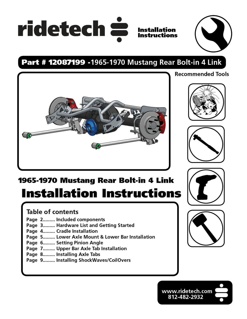
 Part # 12087199-1965-1970 Mustang Rear Bolt-in 4 Link Recommended Tools 1965-1970 Mustang Rear Bolt-in 4 Link Installation Table of contents Page 2... Included components Page 3... Hardware List and Getting
Global West Suspension 655 South Lincoln Ave San Bernardino Ca Phone Fax Web address globalwest.
 Global West Suspension 655 South Lincoln Ave San Bernardino Ca. 92408 Phone 877-470-2975 Fax 909-890-0703 Web address globalwest.net Mustang coilover instruction sheets for 64-66 Kit includes the following
GM C10 Street Grip
 Part # 11365010/11365110-1973-1987 GM C10 StreetGrip Front Components 11369590 Delrin Control Arm Bushings 11369300 Drop Spindles 11362350/11362351 Front CoilSpring Kit 11369515 Front HQ Series Shocks
Installation Instructions Camaro Rear StrongArms. Part # Camaro Rear StrongArm Kit.
 Part # 11505899-2010-2015 Camaro Rear StrongArm Kit Recommended Tools 2010-2015 Camaro Rear StrongArms Installation Table of contents Pages 2-4... Included Components Page 5... Locking Plate and Camber
Part # Chevy Rear AirBar (One Piece Frame)
") 350 S. St. Charles St. Jasper, In. 47546 Ph. 812.482.2932 Fax 812.634.6632 www.ridetech.com Part # 11027199 55-57 Chevy Rear AirBar (One Piece Frame) Components: 1 90000160 Driver side lower axle bracket
350 S. St. Charles St. Jasper, In. 47546 Ph. 812.482.2932 Fax 812.634.6632 www.ridetech.com Part # 11027199 55-57 Chevy Rear AirBar (One Piece Frame) Components: 1 90000160 Driver side lower axle bracket
Next, set the bar level and tighten it down. Do this on both the driver and passenger sides.
 Next, set the bar level and tighten it down. Do this on both the driver and passenger sides. Using two tape measures, measure the outside width at the front and the rear of the tubes. The front dimension
First, check and record the camber and caster readings, they will be adjusted later.
 First, check and record the camber and caster readings, they will be adjusted later. The caliper-mounting bosses are machined perpendicular to the spindle so they are an excellent place for the level.
Installation Instructions
 Part # 099-00 Up Mustang Level Shockwave System Front Components: 0 Front ShockWave Strut Recommended Tools Rear Components: 0 Rear ShockWave Miscellaneous Components: 3033000 3 Gallon Compressor System
Detroit Speed, Inc. Detroit Speed Control Arm and Spindle Kit A-Body P/N: &
 Detroit Speed, Inc. Detroit Speed Control Arm and Spindle Kit 1964-72 A-Body P/N: 030104 & 030105 The Detroit Speed A-Body front suspension kit is a bolt-on package that addresses the shortcomings of the
Installation Instructions
 Part # 12150299-2005 Up Mustang Level 2 Shockwave System Front Components: 12152401 Front ShockWave Strut Recommended Tools Rear Components: 12155401 Rear ShockWave Miscellaneous Components: 30334000 3
Installing the Custom IFS Installing the lower control arms:
 33-34 Ford Car & Truck Chassis Custom IFS & 4-Link Install Instructions Tech Line: 1-855-693-1259 www.totalcostinvolved.com Read and understand these instructions before starting any work! USE THE PARTS
Slide the billet aluminum cap over the bushing and secure with the 3/8-16 x 2 1/2 socket head allen and locknuts provided.
 Slide the billet aluminum cap over the bushing and secure with the 3/8-16 x 2 1/2 socket head allen and locknuts provided. Put the urethane bushings into the upper antiroll-bar-link eyebolt. Coat the bushings
Detroit Speed, Inc. ALUMA-Frame Front Suspension System Ford Mustang P/N:
 Detroit Speed, Inc. ALUMA-Frame Front Suspension System 1964.5-1970 Ford Mustang P/N: 032050 INTRODUCTION All aluminum front suspension system for 1964.5-1970 Mustangs featuring DSE s unique suspension
Detroit Speed, Inc. Front Coilover Kit Race Double Adjustable Camaro P/N:
 Detroit Speed, Inc. Front Coilover Kit Race Double Adjustable 2010+ Camaro P/N: 030321 Item Quantity Description 1 2 Front Strut Assembly (Double Adjustable) 2 2 Coilover Spring 250# x 2.5"ID x 8"L 3 2
Installation Instructions C-10 Rear MuscleBar. Part # C10 Front MuscleBar. Installation Instructions.
 Part # 11369100-1963-1987 C10 Front MuscleBar Recommended Tools 1963-1987 C-10 Rear MuscleBar Table of contents Page 2... Included components and Hardware List Page 3... Getting Started Page 4... MuscleBar
Installing the Custom IFS
 35-40 Ford Car & 35-41 Ford Truck Chassis Custom IFS & 4-Link Install Instructions Tech Line: 1-855-693-1259 www.totalcostinvolved.com Read and understand these instructions before starting any work! USE
Installation Instructions
 Part # 50098-00 Up Camaro Air System Front Components: 300 Front ShockWave Strut Rear Components: 5050 Rear ShockWave Recommended Tools 00 up Camaro Air System Table of contents Pages -9... Front ShockWave
1970 Trans-Am Mustang Front Suspension Instructions. Manual, Volume One, Chassis. Special instructions and precautions will be given
 1970 Trans-Am Mustang Front Suspension Instructions 1. This kit was designed to be used in conjunction with the Rear Suspension kit. 2. This conversion follows standard procedures as described in the 1970
Mustang. MOD1 Coilover Kit FXXADK0100, FXXADK0200, FXXADK0400 FXXA1K0100, FXXA1K0200, FXXA1K0400
 1964.5-1973 Mustang MOD1 Coilover Kit FXXADK0100, FXXADK0200, FXXADK0400 FXXA1K0100, FXXA1K0200, FXXA1K0400 2276 Research Dr. Livermore, Ca 94550 Ph: (925)-443-6300 E: maier@mikemaierinc.com Page 1 of
Note: The transmission mount just happened to be upside down in this picture. (c) 2015 Total Cost Involved Engineering, Inc. All Rights Reserved.
 2015 Total Cost Involved Engineering, Inc. All Rights Reserved.") 1970-1981 Chevy Camaro & Pontiac Firebird Custom IFS Installation Instructions 1-855-693-1259 www.totalcostinvolved.com CHECK ALL PARTS INCLUDED IN THIS KIT TO THE PARTS LIST BEFORE INSTALLATION. IF ANY
1970-1981 Chevy Camaro & Pontiac Firebird Custom IFS Installation Instructions 1-855-693-1259 www.totalcostinvolved.com CHECK ALL PARTS INCLUDED IN THIS KIT TO THE PARTS LIST BEFORE INSTALLATION. IF ANY
~ Installing the Coil-Spring Front End ~
 1935-1940 Ford Car & 1935-1941 Ford Truck Chassis Coil-Spring Front & Leaf Spring Rear Tech line: 1-855-693-1259 www.totalcostinvolved.com Read and understand these instructions before starting any work!
350 S. St. Charles St. Jasper, In Ph Fax
 350 S. St. Charles St. Jasper, In. 47546 Ph. 81.48.93 Fax 81.634.663 www.ridetech.com Part # 1304411 Mopar LX Platform Front Shockwave TQ Series 05-08 Magnum / 05-Up 300C / 06-Up Charger / 08-Up Challenger
Installation Procedure GR40 S197 SLA Front Suspension System (Does not include Aluminum Spindle and Hub Instructions)
") Installation Procedure GR40 S197 SLA Front Suspension System (Does not include Aluminum Spindle and Hub Instructions) Please take the time and read these instructions first! The GR40 S197 system is designed
Installation Procedure GR40 S197 SLA Front Suspension System (Does not include Aluminum Spindle and Hub Instructions) Please take the time and read these instructions first! The GR40 S197 system is designed
USE THE PARTS LIST BELOW TO MAKE SURE YOUR KIT IS COMPLETE BEFORE INSTALLATION. IF ANY PIECES ARE MISSING, PLEASE CONTACT:
 55-59 Chevy Truck Chassis Custom IFS & 4-Link Install Instructions Tech line: 1-855-693-1259 www.totalcostinvolved.com Read and understand these instructions before starting any work! USE THE PARTS LIST
INSTRUCTION S G-Comp Front Suspension: Chevy Nova Speedway Motors, Inc. 2017
 INSTRUCTION S 350-100 G-Comp Front Suspension: 62-67 Chevy Nova Speedway Motors, Inc. 2017 Kit Contents: 91035700 G-Comp Bare Subframe 350101 G-Comp Support Tubes 91035702 G-Comp Front Subframe Hardware
Technical Support Line: (952) Hanover Ave. Lakeville, MN
 Hanover Ave. Lakeville, MN") Technical Support Line: (952) 985-5675 Email: Sales@QA1.net 21730 Hanover Ave. Lakeville, MN 55044 www.qa1.net INSTALLATION INSTRUCTIONS QA1 1967-1979 Mopar A-Body Rear 6 link Conversion System QA1 p/n
Technical Support Line: (952) 985-5675 Email: Sales@QA1.net 21730 Hanover Ave. Lakeville, MN 55044 www.qa1.net INSTALLATION INSTRUCTIONS QA1 1967-1979 Mopar A-Body Rear 6 link Conversion System QA1 p/n
INSTRUCTION S G-Comp Front Suspension: Chevy Camaro Speedway Motors, Inc Kit Contents:
 INSTRUCTION S 350-500 G-Comp Front Suspension: 70-81 Chevy Camaro Speedway Motors, Inc. 2017 Kit Contents: 350500.1 G-Comp Subframe, Camaro 350500.2 G-Comp Sway Bar Kit, Camaro 350500.3 Hardware Kit, G-Comp
Chevrolet 3100 IFS Kit
 1947-54 Chevrolet 3100 IFS Kit Congratulations on your purchase on what we believe is the finest IFS kit available for 1947-54 Chevrolet pickups with stock frames. We have invested many hours into designing
Installation Instructions
 Part # 12150399-2005 Up Mustang Level 3 Shockwave System Front Components: 12152411 Front ShockWave Strut Recommended Tools Rear Components: 12155411 Rear ShockWave Miscellaneous Components: 30314000 3