Sport Sway Bar Kit Mustang
|
|
|
- Ralf Norton
- 6 years ago
- Views:
Transcription


1 Sport Sway Bar Kit Mustang Installation of Hotchkis Front Sway Bar 1F Raising Vehicle Securely block the rear wheels of the vehicle. Use a jack to lift up the front of the vehicle and use jack stands to support it. Do not remove the front wheels during installation for safety.


2 2F Observe Front Bar Once the car is raised, observe the position of the front bar and take note of it s orientation. 3F Remove Subframe Mounts Locate the 2 subframe bushing mounts. Loosen and remove the nuts that secure the bushing brackets to the frame.


3 4F Remove Endlinks and Remove Bar At the ends of the bar, loosen and remove nut that secures the endlinks to the sway bar. The stock bar is now loose and free to be remove. 5F Lube Hotchkis Bushing Grease the inner surface of the Hotchkis bushing with the provided lube.


4 6F Install endlinks onto Sway bar ends Install the Hotchkis bar ends onto the stock endlinks. At this time, determine how stiff you would like your front sway bar. The hole closest to the end is the softest setting. Reuse the stock nut to attached the endlink to the sway bar. Fasten but do not fully tighten these nuts at this time. Leaving these semi loose will aid the rest of the installation. 7F Install Hotchkis Bushing onto the sway bar Once the endlinks are attached, spread open the bushing and install the greased bushing onto the sway bar. Push the bracket onto the bushing.
5 8F Install Hotchkis subframe mounts Rotate the bar up into position and install the Hotchkis bushing brackets onto the subframe. Fully tighten the subframe nuts to secure the bushing bracket. 9F Fully Tighten Endlinks The endlink nuts can now be fully tightened.
6 10F Double Check Hardware Make sure all hardware is fully tightened before driving the vehicle.
7 1R 2R Installation of Hotchkis Rear Sway Bar Raising Car Securely block the front wheels of the vehicle. Use a jack to lift up the rear of the vehicle and support with jack stands. As with the front installation, you should not remove the rear wheels. Observe Rear Bar Once the car is raised, observe the position of the rear bar and take note of it s orientation. 3R Remove Drop links Locate the 2 drop links attaching the chassis and the sway bar. Loosen and remove the bolt that fastens the drop link to the chassis. Retain the mounting bolt for future use. 4R Remove Axle Mounts and Remove the stock bar At the ends of the sway bar, remove the stock bushing brackets. The bar will now be loose and free to remove.
8 5R Install New Hotchkis Drop links Lube the surface of the drop link bushings and install in the same manner as the stock units. Reuse the stock mounting bolt. Fasten but do not fully tighten this bolt at this time. Leaving these semi-loose will aid the rest of the installation. 6R Lube Hotchkis Bushing Grease the inner surface of the Hotchkis bushing with the provided lube.
9 7R Install Hotchkis Bushing onto the sway bar Once the endlinks are attached, spread open the bushing and install the greased bushing onto the sway bar. 8R Install Sway bar to the Drop Links Position the sway bar up close to the drop links and install the bushing brackets as shown in the picture. Use the provided nuts & bolts. You may fully tighten these bolts.
10 9R Prepare Axle Mounts Grease the inner surface of the Hotchkis bushing with the provided lube and place the Hotchkis bracket over it. Next, slide the Hotchkis axle mount peg into the bushing. 10R Install Axle Mounts Using the same stock nuts, install the axle mounts in the same manner as the stock units. The tapped hole in the axle mount peg should face inboard toward to the sway bar.
11 11R Attaching Sway Bar to Axle Mounts At this time, determine how stiff you would like your rear sway bar. The hole closest to the end is the softest setting. Use the provided bolt & washer to secure the sway bar to the axle mounts. Fully Tighten the bolts. 12R Fully Tighten Drop Link Once the sway bar ends are secured, you can now fully tighten the top mounting bolt for the drop links from step 5R.
12 13F Double Check Hardware Make sure all hardware is fully tightened before driving the vehicle.

13 05-Current Ford Mustang 1416 Underbody Brace 05-Current Mustang V6/GT Installation Instructions Thank you for your purchase of this Hotchkis Performance product. Your Underbody Brace set was designed with the performance and durability you ve come to expect from Hotchkis Performance. Note: Please read the entire installation instructions before starting. Having the right tools will ensure a smooth install process.

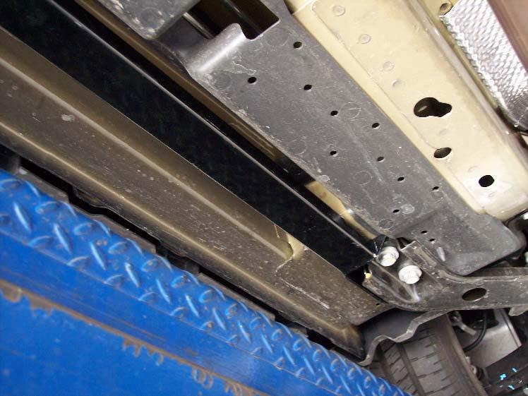
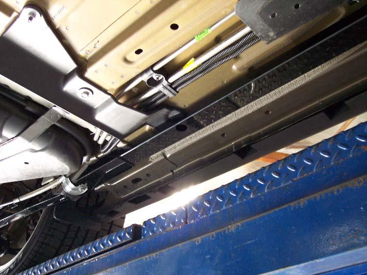
14 05-Current Ford Mustang UNDER BODY BRACE INSTALLATION 1. Safely raise the vehicle and unbolt the stock center bar. NOTE: This is the only stock part that needs to be removed before installation. If it is a later model Mustang where there studs, the nuts will be used in the installation. If there are holes instead of studs, use the supplied hardware. 2. Install the new under brace by hand tightening the four (4) nuts/bolts. If only holes are there use supplied 12mm X 30mm bolts, nylock nuts, and washers. NOTE: Do not tighten these bolts yet. Just start the bolts in the holes so that the brace is supported. This will make it easier to bolt up the rear section.

15 05-Current Ford Mustang 3. Now bolt the rear bracket onto the located in front of the main rear transmission cross member. Use the supplied aluminum spacer, bolt and washer. The aluminum spacer goes between the brace and the chassis for proper positioning. 4. Fully tighten the two (2) rear mounting bolts and the four (4) front mounting nuts/bolts and you are finished.

16 Adjustable Panhard Rod Mustang Thank you for your purchase from our new line of Mustang parts. Tools required for this installation: - Hydraulic jack, jack stands, torque wrench - Metric Sockets and Wrenches - Pry Bar INSTALLATION OF HOTCHKIS PANHARD ROD 1 Raise Vehicle: Securely block the front wheels of the vehicle. Use a jack to lift up the rear of the vehicle and support with jack stands on the rear axle tube. You may also use floor ramps instead of jack stands. 2 Detach Driver Side End:


17 Locate the driver side panhard rod end and remove the plastic cover to reveal the mounting bolt. Retain stock hardware for later use. Loosen and remove bolt. 3 Detach Passenger Side End: Locate the passenger side panhard rod end and loosen & remove the mounting bolt. Retain stock hardware for later use. 4 Remove Panhard Rod and Compare to Hotchkis: Lay the stock panhard rod next to the Hotchkis rod and adjust the Hotchkis rod to the same length. This will give you a good starting point.


18 5 Grease the Hotchkis ends: Grease the flat surface of the polyurethane bushings with the provided lube. 6 Install Hotchkis Panhard Rod: Insert the Hotchkis rod in same manner as stock removal.


19 Reuse the stock hardware to fasten the driver side mount. Do not fully tighten at this time. 8 Attach Passenger Side: Reuse the stock hardware to fasten the passenger side mount. The axle might be slightly shifted from the body, so it may be necessary to use a pry bar to line up the mounting hole with the panhard rod hole. Once the bolt is started, fully tighten both driver and passenger side bolts. Adjusting Panhard Rod:

20 An adjustable panhard rod is used to give the owner the ability to laterally center the rear wheels with the chassis. This is usually needed with lowered vehicles. - Measure the distance between the fender edge and the face of the wheel on each side - If the 2 measurements are different, rotate the Hotchkis panhard rod center to lengthen or shorten it s length. - Re-measure to see if the rear wheels are centered - Repeat if necessary 10 Tighten Jam Nuts: After length adjustment, fully tighten the jam nuts on each side. You are now finished with the installation of your new Hotchkis Adjustable Panhard Rod. Double check to make sure all hardware is fully tighten before driving the vehicle.
21 2011- Ford Mustang GT P/N# Performance Lowering Springs Installation Instructions Thank you for your purchase of this Hotchkis Performance product. Your Lowering Spring set was designed with the performance and durability you ve come to expect from Hotchkis Performance. Note: Please read the entire installation instructions before starting. Having the right tools will ensure a smooth install process.


22 2011- Ford Mustang GT LOWERING SPRINGS INSTALLATION Front 1. Jack the front of the car up and place the car on jack stands. Remove the front wheels. 2. Remove the brake line bracket.


23 2011- Ford Mustang GT 3. Remove the ABS line from the bracket. 4. Unbolt the sway bar link and remove.
 bolts that")

24 2011- Ford Mustang GT 5. Remove the two (2) bolts that hold the spindle to the strut and separate the spindle from the strut

 upper mounting nuts for the strut.")
25 2011- Ford Mustang GT 6. Either use wire or something else to restrain the spindle so the brake line and ABS sensor wiring does not get pulled on. 7. Now remove the four (4) upper mounting nuts for the strut. Just before removing the last nut, support the strut to ensure it from not falling.


26 8. Safely remove the strut assembly Ford Mustang GT


27 2011- Ford Mustang GT 9. Using a spring compressor, compress the spring and remove the upper spring cup nut. NOTE: Use caution when working with a spring compressor!


28 10. Remove the stock springs Ford Mustang GT 11. Remove the coil spring isolator from the old stock coil spring and install it on the new Hotchkis coil spring at the same position.


29 2011- Ford Mustang GT 12. Put in the new Hotchkis coil spring. NOTE: Make sure the end of the spring is up against the stop. If the spring is not seated properly you will not achieve the correct ride height. Also make note to how the coil spring isolator is installed where some of it overlaps the first coil where it is bare.


30 2011- Ford Mustang GT 13. Compress the spring and attach the mounting plate. Ensure proper alignment of the mounting plate and the bottom of the strut by the notch and the lower strut mount and then apply thread lock, and tighten the nut. Please refer to the following pictures for clarification.


31 2011- Ford Mustang GT 14. Place the strut back on the car and repeat on opposite side.

32 2011- Ford Mustang GT Rear 1. Jack one side of the rear of the car up slightly while maintaining the wheel with some contact with the ground. This is just done to support the car while the lower strut bolt is removed 2. Unbolt the lower strut bolt on the slightly raised side. You May need to disconnect the sway bar end link for access to the lower strut bolt.


33 2011- Ford Mustang GT 3. After bolt is removed, fully jack up the slightly lifted side until the suspension drops down and support the lifted side with a jack stand. There should be a flat area to place the jack stand in front of the rear lower control arm. 4. Remove the coil spring. 5. Install the new Hotchkis coil spring.
34 2011- Ford Mustang GT 6. Lower vehicle to compress the spring and align the lower strut mount and tighten mounting bolt. Tighten the sway bar end link if necessary. 7. Fully lower the vehicle and repeat to the other side.
35 Sport Sway Bar Kit Mustang Installation of Hotchkis Front Sway Bar 1F Raising Vehicle Securely block the rear wheels of the vehicle. Use a jack to lift up the front of the vehicle and use jack stands to support it. Do not remove the front wheels during installation for safety.
36 2F Observe Front Bar Once the car is raised, observe the position of the front bar and take note of it s orientation. 3F Remove Subframe Mounts Locate the 2 subframe bushing mounts. Loosen and remove the nuts that secure the bushing brackets to the frame.
37 4F Remove Endlinks and Remove Bar At the ends of the bar, loosen and remove nut that secures the endlinks to the sway bar. The stock bar is now loose and free to be remove. 5F Lube Hotchkis Bushing Grease the inner surface of the Hotchkis bushing with the provided lube.
38 6F Install endlinks onto Sway bar ends Install the Hotchkis bar ends onto the stock endlinks. At this time, determine how stiff you would like your front sway bar. The hole closest to the end is the softest setting. Reuse the stock nut to attached the endlink to the sway bar. Fasten but do not fully tighten these nuts at this time. Leaving these semi loose will aid the rest of the installation. 7F Install Hotchkis Bushing onto the sway bar Once the endlinks are attached, spread open the bushing and install the greased bushing onto the sway bar. Push the bracket onto the bushing.


39 8F Install Hotchkis subframe mounts Rotate the bar up into position and install the Hotchkis bushing brackets onto the subframe. Fully tighten the subframe nuts to secure the bushing bracket. 9F Fully Tighten Endlinks The endlink nuts can now be fully tightened.

40 10F Double Check Hardware Make sure all hardware is fully tightened before driving the vehicle.


41 1R 2R Installation of Hotchkis Rear Sway Bar Raising Car Securely block the front wheels of the vehicle. Use a jack to lift up the rear of the vehicle and support with jack stands. As with the front installation, you should not remove the rear wheels. Observe Rear Bar Once the car is raised, observe the position of the rear bar and take note of it s orientation. 3R Remove Drop links Locate the 2 drop links attaching the chassis and the sway bar. Loosen and remove the bolt that fastens the drop link to the chassis. Retain the mounting bolt for future use. 4R Remove Axle Mounts and Remove the stock bar At the ends of the sway bar, remove the stock bushing brackets. The bar will now be loose and free to remove.


42 5R Install New Hotchkis Drop links Lube the surface of the drop link bushings and install in the same manner as the stock units. Reuse the stock mounting bolt. Fasten but do not fully tighten this bolt at this time. Leaving these semi-loose will aid the rest of the installation. 6R Lube Hotchkis Bushing Grease the inner surface of the Hotchkis bushing with the provided lube.


43 7R Install Hotchkis Bushing onto the sway bar Once the endlinks are attached, spread open the bushing and install the greased bushing onto the sway bar. 8R Install Sway bar to the Drop Links Position the sway bar up close to the drop links and install the bushing brackets as shown in the picture. Use the provided nuts & bolts. You may fully tighten these bolts.


44 9R Prepare Axle Mounts Grease the inner surface of the Hotchkis bushing with the provided lube and place the Hotchkis bracket over it. Next, slide the Hotchkis axle mount peg into the bushing. 10R Install Axle Mounts Using the same stock nuts, install the axle mounts in the same manner as the stock units. The tapped hole in the axle mount peg should face inboard toward to the sway bar.


45 11R Attaching Sway Bar to Axle Mounts At this time, determine how stiff you would like your rear sway bar. The hole closest to the end is the softest setting. Use the provided bolt & washer to secure the sway bar to the axle mounts. Fully Tighten the bolts. 12R Fully Tighten Drop Link Once the sway bar ends are secured, you can now fully tighten the top mounting bolt for the drop links from step 5R.

46 13F Double Check Hardware Make sure all hardware is fully tightened before driving the vehicle.
47 Ford Mustang Adjustable Upper Trailing Arm Current Ford Mustang


48 Current Ford Mustang REMOVAL OF STOCK UPPER TRAILING ARM 1. Raise the vehicle to access the rear end section and lift on the body of the car to ensure the rear end can be dropped. 2. Disconnect the sway bar ends from both sides. 3. Disconnect the rear lower shock mounts on the both sides.


49 Current Ford Mustang 4. Remove bolt from the cabin that is under the rear seat. To gain access, there are two plastic tabs, one on each side that must be pushed in to be able to remove the bottom of the rear seats. 5. Lift car further up to gain access to the upper trailing arm by allowing the differential to droop as far as possible.
 bolts for the upper mount to the upper trailing arm. 7.")
50 Current Ford Mustang 6. Remove the remaining two (2) bolts for the upper mount to the upper trailing arm. 7. Remove the lower mounting bolt of the upper trailing arm to the differential.

51 Current Ford Mustang 8. Remove upper trailing arm from upper mount and adjust the Hotchkis adjustable upper trailing arm to the same center to center length as the stock upper trailing arm. Tighten the jam nuts. Fine adjustments can be made later to set the pinion angle. Details of this is at the end of the installation instructions. 9. Install first the two (2) bolts from the upper mounts by having it finger tight, and then install the third bolt for the upper mount under the rear seat.

52 Current Ford Mustang 10. Connect the lower mount to the differential. To make the bolt align properly during installation, you may need to lift up the differential as shown below. 11. Reconnect the lower shock mounts and sway bar.


53 Current Ford Mustang SETTING PINION ANGLE It may be necessary to set pinion angle after installation of your new Hotchkis upper trailing arms. First of all, what is pinion angle? Pinion angle is basically the angle between the centerline of the differential pinion and the drive shaft centerline. This angle changes during acceleration and braking. If the pinion angle is excessive, then vibration and increased U-joint wear will occur. The Hotchkis double adjustable trailing arms allow you to adjust the pinion angle with ease. Simply loosen the two jam nuts and rotate the aluminum turnbuckle to lengthen or shorten the arm. So, how does one set the pinion angle?

54 Current Ford Mustang The simplest rule of thumb is: The centerline of the differential pinion should be parallel to the centerline of the engine s crankshaft without being the same line. So, the first thing to do is to find out the angle the engine s crankshaft is sitting at. One way to do this is to set a digital angle finder on the front crank pulley or harmonic balancer. Record this angle. Next, set the digital angle finder on the front flat face of the differential yoke. This angle needs to be the same as the recorded crank angle. Adjust your Hotchkis trailing arms to obtain the angle needed. Tighten all hardware and drive the car. Test for driveline vibration by accelerating. If there is vibration during acceleration, then the pinion angle is set too high!


55 Current Ford Mustang Fine tune your Hotchkis trailing arms to achieve the perfect setting for your driving style and horsepower.


56 Current Ford Mustang g Foord Muustang ng Low ower Trailing Tr ng Arms ms WAR RNING: This installatio on involvess removal and re-installation of the rear coil springs. s S Springs sho ould be rem moved and installed i byy a trained technician t f your saffety!! for
 WORK ON ONE SIDE AT A TIME AND DO NOT START THE OTHER SIDE UNTIL FIRST SIDE IS COMPLETELY INSTALLED.")
57 Current Ford Mustang INSTALLATION OF HOTCHKIS PERFORMANCE LOWER TRAILING ARMS 1) Securely block the front wheels of the vehicle. Use a jack to raise the rear of the vehicle and support with jack stands to the frame. 2) WORK ON ONE SIDE AT A TIME AND DO NOT START THE OTHER SIDE UNTIL FIRST SIDE IS COMPLETELY INSTALLED. Disconnect the parking brake cable from the caliper. To do this you must first remove the retaining clip and unhooking the cable from the caliper. 3) Slide the brake cable out of the lower trailing arm. 4) Remove the lower trailing arm by removing both bolts.


58 Current Ford Mustang 5) Using the grease provided, apply a heavy coat of grease to the sides of the bushings at both ends. Apply a light coat of grease to the surface contact areas of the bushing on the frame and axle too. If necessary, clean mating surfaces that are on the car with an abrasive. 6) Install new Hotchkis Lower Trailing Arm. Allow the parking brake caliper to go under the trailing arm as shown in the picture or through the larger window toward the rear of the trailing arm. If the rear axle shifts back, use a pry bar to align the bolt holes. Make sure the Hotchkis grease fittings on the front and back are pointing downward.
 Repeat on to other side. 9) Check that all hardware is in place and tightened. Cover the zerk fittings using the plastic caps provided.")
 or when excessive noise occurs.")
59 Current Ford Mustang 7) If necessary, use a pry bar to move any tab that might interfere with the lower trailing arm about 1/8. 8) Repeat on to other side. 9) Check that all hardware is in place and tightened. Cover the zerk fittings using the plastic caps provided. Use a jack to remove the jack stands, and you re finished installing your new arms. IMPORTANT! For proper maintenance, use the zerk fittings to grease the bushings at least once a year (15,000 miles) or when excessive noise occurs. Use silicon grease available from our website part number # 3101
60 Current Ford Mustang 4016 Subframe Connectors 05-Current Ford Mustang Thank you for your purchase from our new line of Ford parts. Subframe Connectors: Your new subframe connectors will increase the overall rigidity of your chassis and improve handling and response. These engineered components connect the rear frame rails with the front subframe to simulate a complete full frame chassis.

 bolts that hold the rear mount to the front subframe, one")
61 Current Ford Mustang 1. Raise Vehicle It is best to install the subframe connectors at ride height. To do this properly, please use a 4-Post lift or alignment rack. 2. Remove Fasteners Remove the two (2) bolts that hold the rear mount to the front subframe, one (1) bolt and two (2) nuts for the under plastic panel, and the one (1) bolt parking brake cable bracket.


62 Current Ford Mustang 3. Lower the Subframe Lower the subframe by loosening the upper mounting bolts that are located by the control arms. You will need to use an extension and a universal joint to undo these nuts. These nuts do not need to be fully removed, however for safety purposes, only do one side at a time and place a jack underneath the rear subframe mount so that it can be lowered and raised with greater ease. Lower until the subframe connector mounting bracket can easily fit into the gap

 subframe bolts first and then tighten the parking brake cable bracket.")
63 Current Ford Mustang 4. Install Subframe Connector Install the sub frame connector by first mounting the parking brake line bracket and stock bolt loosely and then the two (2) rear subframe mount bolts. For all the bolts, apply thread lock. Tighten those fully down the two (2) subframe bolts first and then tighten the parking brake cable bracket. Then fully remove the front upper subframe bolts to apply thread lock on to them and fully tighten. Again do this one side at a time.


64 Current Ford Mustang 5. Trim the Under Panel Trim the under panel by placing it along the mounting stud and hole and then marking it where it would interfere with the subframe connector. For earlier models where this panel was made from metal, use something like a cutoff wheel or a chop saw for trimming.


65 Current Ford Mustang 6. Attach Under Panel Attach the under panel using the original bolt and nut. Also tight the middle two sections of the subframe connector using the supplied 8mm nylock nut and washer and the 10mm bolt washer. Apply thread lock to all of the bolts. 7. Repeat on Other Side Repeat installation on the other side 8. Double Check Double check all of the hardware and you are finished.
66 Current Ford Mustang
1204AA Ford Mustang Double Adjustable Trailing Arms
 1204AA 79-04 Ford Mustang Double Adjustable Trailing Arms Special Tools Required for this Installation - 4 post lift or alignment rack preferable - Air Chisel, Angle Finder (Digital Preferred), Dead blow
1209A GM B-BODY Double Adjustable Trailing Arms
 1209A 78-96 GM B-BODY Double Adjustable Trailing Arms Warning: This installation should be performed by a trained professional. Tools Required for this Installation - 4 post lift or alignment rack preferable
1203AA GM A-BODY Double Adjustable Trailing Arms
 1203AA 64-67 GM A-BODY Double Adjustable Trailing Arms Warning: This installation should be performed by a trained professional. Note, pictures in this booklet are from a 77-96 GM B Body. Installation
INSTALLATION OF HOTCHKIS PERFORMANCE DOUBLE ADJUSTABLE TRAILING ARMS
 1215 DOUBLE ADJUSTABLE UPPER TRAILING ARMS 67-70 CHEVROLET B-BODY This installation will require: A hydraulic jack, jack stands The following wrenches or sockets: 15/16 Adjustable wrench (1-1/4 1-9/32
2010 Camaro SS/V Underbody Brace Installation Instructions
 2010 Camaro SS/V6 20104 Underbody Brace Installation Instructions Thank you for your purchase of this Hotchkis Performance product. Your Underbody Brace set was designed with the performance and durability
Chrysler A-Body Tubular A-Arms Installation Instructions A-ARM INSTALLATION
 1967-1976 Dodge Demon 1112 67-72 Chrysler A-Body Tubular A-Arms Installation Instructions Thank you for your purchase of this Hotchkis Performance product. Your A-Arm set was designed with the performance
1204AA Ford Mustang Double Adjustable Trailing Arms
 1204AA 79-04 Ford Mustang Double Adjustable Trailing Arms Thank you for your purchase from our new line of Ford parts. Please call us at (877) 4NO-ROLL if you have any questions regarding the service or
Part # Mustang Complete CoilOver Kit
 Front Components: 1 12103509 Front CoilOvers 1 12102899 Lower StrongArms 1 12103699 Upper StrongArms 350 S. St. Charles St. Jasper, In. 47546 Ph. 812.482.2932 Fax 812.634.6632 www.ridetech.com Part # 12100109
SR Performance Sway Bars (2010 Mustang GT)
") Total Installation time: Approximately 2 hours SR Performance Sway Bars (2010 Mustang GT) Tools Required: 15mm deep socket 18mm deep socket 19mm deep socket Ratchet with ½ drive Pliers Torque wrench 15mm
Total Installation time: Approximately 2 hours SR Performance Sway Bars (2010 Mustang GT) Tools Required: 15mm deep socket 18mm deep socket 19mm deep socket Ratchet with ½ drive Pliers Torque wrench 15mm
Part # Mustang Complete CoilOver Kit
 Front Components: Part # 12100109 67-70 Mustang Complete CoilOver Kit 1 12103509 Non Adjustable Front CoilOvers 1 12102899 Lower StrongArms 1 12103699 Upper StrongArms Rear Components: 1 12106509 Non Adjustable
1202AA GM A-BODY Double Adjustable Trailing Arms
 1202AA 68-72 GM A-BODY Double Adjustable Trailing Arms Thank you for your purchase from our new line of GM parts. Please call us at (877) 4NO-ROLL if you have any questions regarding the service or installation
Part # Mustang Rear AirBar
 350 S. St. Charles St. Jasper, In. 47546 Ph. 812.482.2932 Fax 812.634.6632 www.ridetech.com Part # 12087199 64-70 Mustang Rear AirBar Components: 1 90000513 Lower Shockwave mount 1 90000514 Lower Shockwave
Jeep Grand Cherokee ZJ 4 Suspension Kit
 92168800 Jeep Grand Cherokee 93-98 ZJ 4 Suspension Kit Thank you for choosing Rough Country for all your suspension needs. Rough Country recommends a certified technician install this system. In addition
INSTALLATION INSTRUCTIONS Progress Technology Rear Anti-Sway Bar Honda Civic Part # No Revision (7/20/16)
") INSTALLATION INSTRUCTIONS Progress Technology Rear Anti-Sway Bar Honda Civic 96-00 Part # 62.1042 No Revision (7/20/16) WHO SHOULD INSTALL THIS PRODUCT? Progress Technology products should only be installed
INSTALLATION INSTRUCTIONS Progress Technology Rear Anti-Sway Bar Honda Civic 96-00 Part # 62.1042 No Revision (7/20/16) WHO SHOULD INSTALL THIS PRODUCT? Progress Technology products should only be installed
Part # Mustang Complete SA CoilOver Kit
 Front Components: 350 S. St. Charles St. Jasper, In. 47546 Ph. 812.482.2932 Fax 812.634.6632 www.ridetech.com Part # 12100210 67-70 Mustang Complete SA CoilOver Kit 1 12103510 Single Adjustable Front CoilOvers
AEV30308AA Last Updated: 05/31/18. 4 DUALSPORT sc SUSPENSION system for RAM 1500 air ride standard and rebel INSTALLATION GUIDE
 AEV30308AA Last Updated: 05/31/18 4 DUALSPORT sc SUSPENSION system for RAM 1500 air ride standard and rebel INSTALLATION GUIDE PLEASE READ BEFORE YOU START TO GUARANTEE A QUALITY INSTALLATION, WE RECOMMEND
INSTALLATION INSTRUCTIONS CHEVY C-10 4-Link Rear End
 INSTALLATION INSTRUCTIONS 73-87 CHEVY C-10 4-Link Rear End Please read these instructions completely before starting your installation. Assemble suspension on vehicle before powder-coating to ensure proper
Installation Instructions
 Part # 12087199-1965-1970 Mustang Rear Bolt-in 4 Link Recommended Tools 1965-1970 Mustang Rear Bolt-in 4 Link Installation Table of contents Page 2... Included components Page 3... Hardware List and Getting
Sport Sway Bar Kit VW Golf (GTI ), Jetta
, Jetta") Sport Sway Bar Kit 22813 VW Golf (GTI ), Jetta Thank you for your purchase from our new line of VW parts. Please call us at (877) 4NO - ROLL if you have any questions regarding the service or installation
Sport Sway Bar Kit 22813 VW Golf (GTI ), Jetta Thank you for your purchase from our new line of VW parts. Please call us at (877) 4NO - ROLL if you have any questions regarding the service or installation
INSTALLATION INSTRUCTION 88581
 INSTALLATION INSTRUCTION 88581 FOR RANCHO SUSPENSION SYSTEM RS6581B: DODGE RAM READ ALL INSTRUCTIONS THOROUGHLY FROM START TO FINISH BEFORE BEGINNING INSTALLATION Rev C IMPORTANT NOTES! WARNING: This suspension
REAR UPPER CONTROL ARM
 CHE PERFORMANCE PRODUCTS INSTALLATION INSTRUCTIONS REAR UPPER CONTROL ARM CHE2K: Tubular Upper: 2005-2010 Mustang CHE2L: Street/Strip Adjustable Upper: 2005-2010 Mustang CHE2M: Competition Adjustable Upper:
Suspension System RS6582B
 Suspension System RS6582B Tahoe/Yukon READ ALL INSTRUCTIONS THOROUGHLY FROM START TO FINISH BEFORE BEGINNING INSTALLATION IMPORTANT NOTES! WARNING: This suspension system will enhance the off-road performance
Part # Galaxie Air Suspension System
 350 S. St. Charles St. Jasper, In. 47546 Ph. 812.482.2932 Fax 812.634.6632 www.ridetech.com Part # 12160298 60-64 Galaxie Air Suspension System Front Components: 1 12162401 Master Series Single Adjustable
Lightweight Tubular Sway Bar Kit Subaru WRX / STi / 09+ FXT
 915250 Lightweight Tubular Sway Bar Kit 2008+ Subaru WRX / STi / 09+ FXT Installation Instructions Congratulations on your purchase of the COBB Lightweight Tubular Sway Bar Kit for your Subaru WRX, STi
INSTALLATION INSTRUCTIONS 88518
 INSTALLATION INSTRUCTIONS 88518 For Rancho Suspension Systems RS6518: 2009 FORD F-150 4WD READ ALL INSTRUCTIONS THOROUGHLY FROM START TO FINISH BEFORE BEGINNING INSTALLATION Rev A IMPORTANT NOTES! WARNING:
Note: The transmission mount just happened to be upside down in this picture. (c) 2015 Total Cost Involved Engineering, Inc. All Rights Reserved.
 2015 Total Cost Involved Engineering, Inc. All Rights Reserved.") 1970-1981 Chevy Camaro & Pontiac Firebird Custom IFS Installation Instructions 1-855-693-1259 www.totalcostinvolved.com CHECK ALL PARTS INCLUDED IN THIS KIT TO THE PARTS LIST BEFORE INSTALLATION. IF ANY
1970-1981 Chevy Camaro & Pontiac Firebird Custom IFS Installation Instructions 1-855-693-1259 www.totalcostinvolved.com CHECK ALL PARTS INCLUDED IN THIS KIT TO THE PARTS LIST BEFORE INSTALLATION. IF ANY
INSTALLATION INSTRUCTIONS 64 ½ - 70 SUPERRIDE II INDEPENDENT FRONT SUSPENSION BX-350 FOR COYOTE AND MOD ENGINES
 INSTALLATION INSTRUCTIONS 64 ½ - 70 SUPERRIDE II INDEPENDENT FRONT SUSPENSION BX-350 FOR COYOTE AND MOD ENGINES Please read these instructions completely before starting your installation. Assemble suspension
KDT916 - Watts Link - Complete Assembly
 KDT916 - Watts Link - Complete Assembly Please read all instructions carefully prior to installation and verify all kit contents and tools are on hand prior to installation. Professional Installation by
INSTALLATION INSTRUCTION 88088
 INSTALLATION INSTRUCTION 88088 For Rancho Suspension Systems RS6588 & RS6589: FORD F-150 READ ALL INSTRUCTIONS THOROUGHLY FROM START TO FINISH BEFORE BEGINNING INSTALLATION Rev B IMPORTANT NOTES! WARNING:
GM F-Body Convertible 1404 Center X-Brace Installation Instructions
 1967-1969 GM F Body 1967-1969 GM F-Body Convertible 1404 Center X-Brace Installation Instructions Thank you for your purchase of this Hotchkis Performance product. Your X-Brace was designed with the performance
RHINO SUSPENSION SYSTEM INSTALLATION INSTRUCTIONS
 PARTS INCLUDED: 2 FRONT UPPER A-ARMS 2 FRONT LOWER A-ARMS 2 UNI-BALL JOINTS 2 UNI-BALL JOINT STUDS 2 UNI-BALL JOINT CAPS 2 RETAINING RINGS 1 FRONT SHOCK ASSEM. 2 DELRON STEERING STOPS 2 SHOCK MOUNT SPACERS
PPM-8023 / PPM-8043 JEEP JK SYNERGY STAGE 3 SUSPENSION SYSTEM Version 1
 SYNERGY MFG. 870 INDUSTRIAL WAY, SAN LUIS OBISPO, CA (805) 242-0397 PPM-8023 / PPM-8043 JEEP JK SYNERGY STAGE 3 SUSPENSION SYSTEM Version 1 GENERAL NOTES: These instructions are also available on our website;
PPM-8022 / PPM-8042 JEEP JK STAGE 2 SYNERGY SUSPENSION SYSTEM Version 1
 POLY PERFORMANCE MFG. 870 INDUSTRIAL WAY, SAN LUIS OBISPO, CA (805) 242-0397 PPM-8022 / PPM-8042 JEEP JK STAGE 2 SYNERGY SUSPENSION SYSTEM Version 1 GENERAL NOTES: These instructions are also available
Installation Instructions
 Installation Instructions Jeep TJ Long Arm Suspension System 1997-2002 JEEP TJ 4WD 6 1997-2002 JEEP TJ 4WD FTS24002 & BK / FTS24003 & BK / FTS44002 & BK PARTS LIST FTS24002BK Jeep TJ 6' Box Kit 1 FTS24003BK
INSTALLATION INSTRUCTION Rev A
 INSTALLATION INSTRUCTION 88587 Rev A FOR RANCHO SUSPENSION SYSTEM RS6587B: 2009 DODGE RAM 1500 READ ALL INSTRUCTIONS THOROUGHLY FROM START TO FINISH BEFORE BEGINNING INSTALLATION IMPORTANT NOTES! WARNING:
05-07 F /2 SUSPENSION KIT
 92147900 05-07 F250 4 1/2 SUSPENSION KIT Thank you for choosing Rough Country for your suspension needs. Rough Country recommends a certified technician installs this system. In addition to these instructions,
CSS-C CHEVROLET SUBURBAN & TAHOE WD AND 2WD CHEVROLET AVALANCHE WD AND 2WD 6-8 SUSPENSION LIFT KIT
 14385 Veterans Way Moreno Valley, CA 92553 Phone: (951) 571-0212 Fax: (951) 571-0215 WWW.CSTSUSPENSION.COM CSS-C3-3 2000-2006 CHEVROLET SUBURBAN & TAHOE 1500 4WD AND 2WD 2002-2006 CHEVROLET AVALANCHE 1500
FTS & 8 RADIUS ARM BOX KIT
 FTS22139 6 & 8 RADIUS ARM BOX KIT 2008-2015 FORD F-250/350 SUPER DUTY 4WD 2008 2015 FORD F-250/350 SUPER DUTY 4WD FTS22139 6 & 8 RADIUS ARM KIT FTS22139 6"&8" Radius Arm Box Kit FT30287 Hardware Kit Qty
Part # GM F Body Rear R-Joint Bolt-in 4 Link GM F Body Rear Bolt-in 4Link. Table of contents. Installation Instructions
 Part # 11167199-1967-1969 GM F Body Rear R-Joint Bolt-in 4 Link Recommended Tools 1967-1969 GM F Body Rear Bolt-in 4Link Installation Table of contents Page 2-3... Included Components Page 4... Hardware
Vehicle ride height chart
 Please read Instructions thoroughly and completely before beginning installation. Installation by a certified mechanic is recommended. ReadyLIFT Suspension Inc. is NOT responsible for any damage or failure
MM Adjustable IRS Tie-Rod (MMIRSTR-2)
") 3430 Sacramento Dr., Unit D San Luis Obispo, CA 93401 Telephone: 805/544-8748 Fax: 805/544-8645 www.maximummotorsports.com MM Adjustable IRS Tie-Rod (MMIRSTR-2) Sample Bumpsteer Curve: Read all instructions
3430 Sacramento Dr., Unit D San Luis Obispo, CA 93401 Telephone: 805/544-8748 Fax: 805/544-8645 www.maximummotorsports.com MM Adjustable IRS Tie-Rod (MMIRSTR-2) Sample Bumpsteer Curve: Read all instructions
Part # GM F Body Complete CoilOver System
 350 S. St. Charles St. Jasper, In. 47546 Ph. 812.482.2932 Fax 812.634.6632 www.ridetech.com Part # 11170109 70-81 GM F Body Complete CoilOver System Front Components: 1 11173509 Front Fixed Valving CoilOvers
INSTALLATION INSTRUCTION 89400
 INSTALLATION INSTRUCTION 89400 FOR RANCHO SUSPENSION SYSTEM RS66400B: 2012 RAM 1500 4WD. READ ALL INSTRUCTIONS THOROUGHLY FROM START TO FINISH BEFORE BEGINNING INSTALLATION Rev B IMPORTANT NOTES! WARNING:
Steeda Sport Mustang Lowering Springs (2005+) - Installation Instructions
 - Installation Instructions") Steeda Sport Mustang Lowering Springs (2005+) - Installation Instructions The below installation instructions work for the following products: Steeda Sport Mustang Lowering Springs (2005+) Please read
Steeda Sport Mustang Lowering Springs (2005+) - Installation Instructions The below installation instructions work for the following products: Steeda Sport Mustang Lowering Springs (2005+) Please read
Cobra IRS Aluminum Differential Bushings (MMIRSB-40.2)
") 3430 Sacramento Dr., Unit D San Luis Obispo, CA 93401 Telephone: 805/544-8748 Fax: 805/544-8645 www.maximummotorsports.com Cobra IRS Aluminum Differential Bushings (MMIRSB-40.2) The MM front differential
3430 Sacramento Dr., Unit D San Luis Obispo, CA 93401 Telephone: 805/544-8748 Fax: 805/544-8645 www.maximummotorsports.com Cobra IRS Aluminum Differential Bushings (MMIRSB-40.2) The MM front differential
Ford Racing GT500 Style Strut Mount Upgrade (05-12 All):
:") Ford Racing GT500 Style Strut Mount Upgrade (05-12 All): Required tools: (2) Jack stands Floor jack (1 is required but 2 is preferred) Torque wrench Spring compressor tool (can be rented at your local
Ford Racing GT500 Style Strut Mount Upgrade (05-12 All): Required tools: (2) Jack stands Floor jack (1 is required but 2 is preferred) Torque wrench Spring compressor tool (can be rented at your local
PRE-INSTALLATION. INSTALLATION INSTRUCTIONS Front Dodge Ram WD 6" Suspension Lift Kit
 2012-2015 Dodge Ram 1500 4WD 6" Suspension Lift Kit PRE-INSTALLATION 35015 2 - Knuckle (Driv/Pass) 2 - Crossmember (Front/Rear) 2 - Differential Bracket (Driv/Pass) 1 - Diff. Brace Bracket (Pass) 2 - Front
1 M-3000-H4 F150 4X4 Lowering Kit
 READ INSTRUCTIONS COMPLETELY THROUGH BEFORE STARTING. IT IS RECOMMENDED THAT INSTALLATION BE DONE BY A QUALIFIED MECHANIC. REPLACE ALL STOCK PARTS THAT ARE DAMAGED OR WORN. ALWAYS WEAR EYE PROTECTION.
2.5" & 3.5" SUSPENSION SYSTEM JEEP JK WRANGLER 2 & 4 DOOR MODELS
 2.5" & 3.5" SUSPENSION SYSTEM 2007-2018 JEEP JK WRANGLER 2 & 4 DOOR MODELS JSPEC2352 www.jksmfg.com jks@ridefox.com 517-278-1226 RV. 100818 GETTING STARTED Read all warnings, instructions, notes and cautions
Installation Notes: #86000-R Race Series +3.5 L/T Kit
 159 North Maple St. Unit J, CORONA CA 92880 P. 951-737-9682 F. 951-737-9006 WWW.CHAOSFAB.COM Installation Notes: #86000-R Race Series +3.5 L/T Kit Factory manual is recommended for removal and re-installation
Detroit Speed, Inc. Detroit Speed/JRi Front Strut Kit Camaro/Firebird P/N: & D
 Detroit Speed, Inc. Detroit Speed/JRi Front Strut Kit 1982-92 Camaro/Firebird P/N: 030332 & 030332D The Detroit Speed/JRi Front Strut Kit is a high-performance aluminum body strut body with Detroit Tuned
04-08 FORD F150 4 KIT
 9257700 04-08 FORD F50 4 KIT THANK YOU FOR CHOOSING ROUGH COUNTRY FOR YOUR SUSPENSION NEEDS. Rough Country recommends a certified technician install this system. In addition to these instructions, professional
INSTALLATION INSTRUCTION 88094
 INSTALLATION INSTRUCTION 88094 FOR RANCHO SUSPENSION SYSTEM RS6594B 4WD & 2WD NISSAN TITAN READ ALL INSTRUCTIONS THOROUGHLY FROM START TO FINISH BEFORE BEGINNING INSTALLATION Rev D IMPORTANT NOTES! WARNING:
Z8004. KDT916 S197 Performance Watts Linkage
 Z8004 KDT916 S197 Performance Watts Linkage Kit Includes: Differential Cover o Magnetic Plug o Standard Plug o Main Brace o Center Pivot o Swivel Foot Bolts 2 o Swivel Foot Retaining nuts 2 o M12x30 Bolt
Installation Instructions for Teraflex 2.5 Inch Lift Kit with Shocks (2010 Jeep Wrangler Unlimited)
") Installation Instructions for Teraflex 2.5 Inch Lift Kit with Shocks (2010 Jeep Wrangler Unlimited) Installation Time: 6 Hours Tools Required: Floor Jack Jack Stands Ratchet Torque Wrench 15mm Socket 15mm
Installation Instructions for Teraflex 2.5 Inch Lift Kit with Shocks (2010 Jeep Wrangler Unlimited) Installation Time: 6 Hours Tools Required: Floor Jack Jack Stands Ratchet Torque Wrench 15mm Socket 15mm
WATTS LINK INSTALLATION INSTRUCTIONS
 TOOLS REQUIRED: WL005, WL006 Hydraulic jack and jack stands Wrenches and sockets: 15mm, 18mm, 19mm, 22mm, 9/16, ¾, 15/16 Small level INSTALLATION: 1. Lift the rear of the vehicle and safely support with
MM Caster/Camber Plates, (Mm5CC-7)
") 3430 Sacramento Dr., Unit D San Luis Obispo, CA 93401 Telephone: 805/544-8748 Fax: 805/544-8645 www.maximummotorsports.com MM Caster/Camber Plates, 2005-14 (Mm5CC-7) Supplemental Installation Notes This
3430 Sacramento Dr., Unit D San Luis Obispo, CA 93401 Telephone: 805/544-8748 Fax: 805/544-8645 www.maximummotorsports.com MM Caster/Camber Plates, 2005-14 (Mm5CC-7) Supplemental Installation Notes This
CSS-C SUSPENSION LIFT KIT
 115 W. La Cadena Dr. Ste 100 Riverside, CA 92501 (951) 328-9902 phone (951) 328-9908 fax 2000-2006 CHEVROLET SILVERADO 1500 4WD CSS-C3-2 6-8 SUSPENSION LIFT KIT WARNING: CALIFORNIA SUPERTRUCKS RECOMMENDS
Part # Chevy Level 2 CoilOver Suspension Package Two Piece Frame
 350 S. St. Charles St. Jasper, In. 47546 Ph. 812.482.2932 Fax 812.634.6632 www.ridetech.com Part # 11030210 55-57 Chevy Level 2 CoilOver Suspension Package Two Piece Frame Front Components: 1 11013510
928 Specialists Rear Sway Bar Installation
 928 Specialists Rear Sway Bar Installation This document is also available for download on our website (www.928gt.com/rearswaybarinstall.htm). Any new revisions to these original instructions can be found
2216 (STOCK) / 2224 (3 LOWER) 2WD SPORT SWAY BAR SET 97-UP DODGE DAKOTA INSTALLATION OF HOTCHKIS PERFORMANCE FRONT SWAY BAR
 / 2224 (3 LOWER) 2WD SPORT SWAY BAR SET 97-UP DODGE DAKOTA INSTALLATION OF HOTCHKIS PERFORMANCE FRONT SWAY BAR") 2216 (STOCK) / 2224 (3 LOWER) 2WD SPORT SWAY BAR SET 97-UP DODGE DAKOTA Thank you for your purchase from our line of Dodge Dakota & Durango suspension parts. Please call us at (877) 4NO-ROLL if you have
2216 (STOCK) / 2224 (3 LOWER) 2WD SPORT SWAY BAR SET 97-UP DODGE DAKOTA Thank you for your purchase from our line of Dodge Dakota & Durango suspension parts. Please call us at (877) 4NO-ROLL if you have
2.5" & 3.5" SUSPENSION SYSTEM
 2.5" & 3.5" SUSPENSION SYSTEM 2007-2014 JEEP JK WRANGLER 2 & 4 DOOR MODELS JSPEC2352 www.jksmfg.com jks@sporttruckusainc.com 517-278-1226 Rv. 071814 Getting Started Read all warnings, instructions, notes
COBB SPORT SPRINGS
 915760 - COBB SPORT SPRINGS 2008-2013 Subaru WRX/STi Congratulations on your purchase of the COBB Sport Springs for your 2008-2013 Subaru WRX/STi. The following instructions will assist you through your
Part # Chevy Level 2 Air Suspension Package One Piece Frame
 350 S. St. Charles St. Jasper, In. 47546 Ph. 812.482.2932 Fax 812.634.6632 www.ridetech.com Part # 11020299 55-57 Chevy Level 2 Air Suspension Package One Piece Frame Front Components: 1 11013001 Master
60-65 Falcon, Comet & Ranchero Coil Spring IFS
 60-65 Falcon, 62-65 Comet & 62-65 Ranchero Coil Spring IFS All engine installations with this front end will require a rear sump oil pan. 289-302 Small Block Ford Motors Milodon rear sump pan holds 7 quarts
KIT # CSS-C SUSPENSION LIFT KIT
 14385 Veterans Way Moreno Valley, CA 92553 Phone: (951) 571-0212 Fax: (951) 571-0215 2001-2010 CHEVROLET SILVERADO 1500 AND 2500 HD 4WD AND 2WD PICK-UP 1999-2010 CHEVY 2500 4WD PICK-UPS 2001-2010 2500
EVO Manufacturing. 2.5 /3.5 Jeep Wrangler JL Enforcer Kit Instruction Manual. for all: EVO-3011, EVO-3012, EVO-3013, EVO-3014 Kits
 EVO Manufacturing 2.5 /3.5 Jeep Wrangler JL 2018+ Enforcer Kit Instruction Manual for all: EVO-3011, EVO-3012, EVO-3013, EVO-3014 Kits READ BEFORE INSTALL: 2.5 JL Enforcer/Enforcer Overland kits with either
Detroit Speed, Inc. Caster/Camber Plate Kit Camaro/Firebird P/N:
 Detroit Speed, Inc. Caster/Camber Plate Kit 1982-92 Camaro/Firebird P/N: 030330 The Detroit Speed Inc., Caster/Camber Plate Kit is a direct bolt-on kit that allows precise camber and caster adjustments
INSTALLATION INSTRUCTIONS
 INSTALLATION INSTRUCTIONS 2005-2012 Nissan Xterra/Frontier / Pathfinder PART NUMBERS: NP17500, NP17525, NP17550 FRONTIER PARTS & CORRESPONDING HARDWARE LIST XTERRA PATHFINDER ABOVE LISTED 1/2 Metal Lock
Maximum Motorsports Camber Caster Plates (05-10):
:") Maximum Motorsports Camber Caster Plates (05-10): Tools Required: Lug Wrench 21mm Deep Socket 18mm Deep Socket 15mm Deep Socket 17mm Socket 13mm Socket 10mm Socket Torque Wrench (requires 166lb-ft capacity
Maximum Motorsports Camber Caster Plates (05-10): Tools Required: Lug Wrench 21mm Deep Socket 18mm Deep Socket 15mm Deep Socket 17mm Socket 13mm Socket 10mm Socket Torque Wrench (requires 166lb-ft capacity
PRODUCT USE INFORMATION
 921545200 *54520BAG1* 54520BAG1 Thank you for choosing Rough Country for all your suspension needs. 2009-17 Ford F150 3 Suspension Kit Rough Country recommends a certified technician install this system.
JK 3 Install Kit Instruction Pack
 JK 3 Install Kit Instruction Pack 1 Contents: Rear Sway Bar Link Instructions Spring Instructions Bumpstop Instructions Rear Track Bar Bracket Instructions Extended Brake Line Instructions Quick Disconnect
INSTALLATION INSTRUCTIONS `64 ½ - 70 MUSTANG, HEIDTS IFS, PRO-G GEN II P/N: MTF-201
 INSTALLATION INSTRUCTIONS `64 ½ - 70 MUSTANG, HEIDTS IFS, PRO-G GEN II P/N: MTF-201 Please read these instructions completely Before starting your installation. Assemble suspension on vehicle before powder-coating
*1576BAG9* 1576BAG FORD F KIT C THANK YOU FOR CHOOSING ROUGH COUNTRY FOR YOUR SUSPENSION NEEDS.
 957600C THANK YOU FOR CHOOSING ROUGH COUNTRY FOR YOUR SUSPENSION NEEDS. 0-08 FORD F50-6 KIT Rough Country recommends a certified technician install this system. In addition to these instructions, professional
04-08 FORD F150 6 KIT
 957600 THANK YOU FOR CHOOSING ROUGH COUNTRY FOR YOUR SUSPENSION NEEDS. 0-08 FORD F50 6 KIT Rough Country recommends a certified technician install this system. In addition to these instructions, professional
STOP---READ THIS FIRST!
 STOP---READ THIS FIRST! **Read These Entire Instructions Before Starting Anything** 2007-2013 GM 1500 TRUCK LIFT KIT INSTRUCTIONS (PART# 50700 & 50720) 5680 W. Barstow, Fresno, CA 93722 PH: (559) 226-8196
INSTALLATION INSTRUCTIONS Chevrolet Nova Superide II Independent Front Suspension
 INSTALLATION INSTRUCTIONS 1962 1967 Chevrolet Nova Superide II Independent Front Suspension Please read these instructions completely before starting your installation. Assemble suspension on vehicle before
PRE-INSTALLATION. INSTALLATION INSTRUCTIONS Front Ford F150 4WD 4" Suspension Lift Kit
 2015 Ford F150 4WD 4" Suspension Lift Kit PRE-INSTALLATION 2 - Knuckle (Driv/Pass) 2 - Crossmember (Front/Rear) 2 - Differential Bracket (Driv/Pass) 1 - Diff. Brace Bracket (Pass) 2 - Front Brake Line
Alignment Spec. Power Rack & Pinion: 5 degrees positive Camber 0 degrees Toe-In 1/32
 333-TCIE237 1967-1969 Chevy Camaro Front Suspension 1968-1972 Chevy Nova Front Suspension 1967-1969 Pontiac Firebird Front Suspension 1-800-984-6259 www.totalcostinvolved.com 1967-1969 Chevy Camaro Front
350 S. St. Charles St. Jasper, In Ph Fax
 350 S. St. Charles St. Jasper, In. 47546 Ph. 812.482.2932 Fax 812.634.6632 www.ridetech.com Part # 11167197 67-69 GM F Body AirBar Components: 1 90000527 Upper cradle assembly 1 90002077 Lower axle bracket
TOYOTA FJ CRUISER 6 SUSPENSION KIT
 92177000 TOYOTA FJ CRUISER 6 SUSPENSION KIT Thank you for choosing Rough Country for your suspension needs. Rough Country recommends a certified technician installs this system. In addition to these instructions,
INSTALLATION INSTRUCTION 88146
 INSTALLATION INSTRUCTION 88146 Rev H FOR RANCHO SUSPENSION SYSTEM RS6547: 4WD SUBURBAN/YUKON XL, 4WD TAHOE/YUKON, & 4WD AVALANCHE READ ALL INSTRUCTIONS THOROUGHLY FROM START TO FINISH BEFORE BEGINNING
Installations Instructions for Maier Racing Front Coilover Kit MS Ford Mustang
 22215 Meekland Avenue Hayward, CA 94541 Phone: (510) 581-7600 Fax: (510) 581-2406 Installations Instructions for Maier Racing Front Coilover Kit MS-02-001 1964-1973 Ford Mustang Contents Front Coilover
Class 8.8 Class MM 18ft/lbs 23 ft/lbs 10MM 32ft/lbs 45ft/lbs 12MM 55ft/lbs 75ft/lbs 14MM 85ft/lbs 120ft/lbs
 92190500 Jeep Grand Cherokee 93-98 ZJ 4 Longarm Thank you for choosing Rough Country for all your suspension needs. Rough Country recommends a certified technician install this system. In addition to these
97-06 JEEP TJ/LJ LONG ARM UPGRADE KIT
 921663U00 97-06 JEEP TJ/LJ LONG ARM UPGRADE KIT Thank you for choosing Rough Country for your suspension needs. This kit is an upgrade kit only. This kit includes frame mounting points and adjustable long
05-07 F250 6 SUSPENSION KIT
 92159300 Stabilizer Drop Brackets Track Bar Bracket Control Arm Bracket Brake Line Drop Bracket Sway Bar Link Ext. Hardware Bags Pitman Arm 6111 Add-a-leaf 6578 3 Block and U-Bolt Kit 05-07 F250 6 SUSPENSION
TOYOTA 4-RUNNER KIT 5 KIT
 92173600 1990-1995 TOYOTA 4-RUNNER KIT 5 KIT Thank you for choosing Rough Country for all your suspension needs. Rough Country recommends a certified technician install this system. In addition to these
PRE-INSTALLATION. INSTALLATION INSTRUCTIONS STEP 1: Park vehicle on level surface and chock rear wheels.
 2007-2013 7.5" GMC/Chevrolet 1500 4WD Suspension Lift kit PRE-INSTALLATION 15004 2 - Cross-member (Fr/Rr) 2 - Sway Bar Drop Bracket 2 - Knuckle (Dr/Pass) 1 - Driver Diff. Bracket 1 - Passenger Diff. Bracket
2014 GM 1500 TRUCK STOP---READ THIS FIRST! 7" Lift KIT. **Read These Entire Instructions Before Starting Anything**
 STOP---READ THIS FIRST! **Read These Entire Instructions Before Starting Anything** 2014 GM 1500 TRUCK LIFT KIT INSTRUCTIONS (PART #50768 & #50769 ) 5680 W. Barstow, Fresno, CA 93722 PH: (559) 226-8196
Detroit Speed, Inc. DSE/JRi Front Strut Kit Camaro/Firebird P/N: & D
 Detroit Speed, Inc. DSE/JRi Front Strut Kit 1982-92 Camaro/Firebird P/N: 030332 & 030332D The DSE/JRi Front Strut Kit is a high-performance aluminum body strut body with Detroit Tuned valving. The kit
NOTICE- THIS K-MEMBER REQUIRES THE USE OF COIL OVER SUSPENSION. K-MEMBER WILL NOT WORK WITH FACTORY STYLE SPRINGS.
 Technical Support Line: (952) 985-5675 Email: Info@QA1.net 21730 Hanover Ave. Lakeville, MN 55044 www.qa1.net INSTALLATION INSTRUCTIONS MUSTANG K-MEMBER P/N MUK11, MUK12, MUK13 NOTICE- THIS K-MEMBER REQUIRES
Installation Guide for Rough Country 2.5 inch Lift Kit w/o Shocks (07-15 Wrangler JK) Item # J10212
 Item # J10212") Installation Guide for Rough Country 2.5 inch Lift Kit w/o Shocks (07-15 Wrangler JK) Item # J10212 Installation Time: 3 Hours Tools Required: Jack (2 helps, but not needed) Jack stands(2 3-ton, 2 2-ton)
Installation Guide for Rough Country 2.5 inch Lift Kit w/o Shocks (07-15 Wrangler JK) Item # J10212 Installation Time: 3 Hours Tools Required: Jack (2 helps, but not needed) Jack stands(2 3-ton, 2 2-ton)
6 Suspension System. Dodge wd Part#:
 Part#: 012622 6 Suspension System Dodge 2500 4wd 2009-2013 Rev. 010218 491 W. Garfield Ave., Coldwater, MI 49036. Phone: 517-279-2135 E-mail: tech-bds@sporttruckusainc.com Read And Understand All Instructions
2.5" & 3.5" SUSPENSION SYSTEM 2018 JEEP JL WRANGLER 4 DOOR MODELS
 2.5" & 3.5" SUSPENSION SYSTEM 2018 JEEP JL WRANGLER 4 DOOR MODELS JSPEC1202/JSPEC1203 www.jksmfg.com jks@sporttruckusainc.com 517-278-1226 RV. 050318 GETTING STARTED Read all warnings, instructions, notes
Team Z Motorsports. K-Member installation instructions
 Team Z Motorsports K-Member installation instructions Parts Included: 1-Tubular K-Member Needed Items-Solid Steering Shaft Offset Steering Rack Bushings Optional-Heavy Duty Bolt Kit Tubular Front Lower
97-06 JEEP TJ 3 1/4 PROGRESSIVE COIL/SPACER KIT
 92PERF1641 97-06 JEEP TJ 3 1/4 PROGRESSIVE COIL/SPACER KIT Thank you for choosing Rough Country for your suspension needs. Rough Country recommends a certified technician installs this system. In addition
Part # Chevy Rear AirBar (One Piece Frame)
") 350 S. St. Charles St. Jasper, In. 47546 Ph. 812.482.2932 Fax 812.634.6632 www.ridetech.com Part # 11027199 55-57 Chevy Rear AirBar (One Piece Frame) Components: 1 90000160 Driver side lower axle bracket
350 S. St. Charles St. Jasper, In. 47546 Ph. 812.482.2932 Fax 812.634.6632 www.ridetech.com Part # 11027199 55-57 Chevy Rear AirBar (One Piece Frame) Components: 1 90000160 Driver side lower axle bracket
09-12 Dodge 4WD Leveling Kit
 9235900 09-12 Dodge 4WD 1500 2.5 Leveling Kit Thank you for choosing Rough Country for all your suspension needs. DOES NOT FIT TRX PACKAGE VEHICLES!! Rough Country recommends a certified technician install
CHECK ALL PARTS INCLUDED IN THIS KIT TO THE PARTS LIST BEFORE INSTALLATION. IF ANY PIECES ARE MISSING, PLEASE CONTACT: TOTAL COST INVOLVED
 333-TCIE237 1967-1969 Chevy Camaro Front End, 1968-1972 Chevy Nova Front End 1967-1969 Pontiac Firebird Front End Suspension Installation Instructions 1-855-693-1259 www.totalcostinvolved.com CHECK ALL
OME SUSPENSION KIT INSTALLATION FJ CRUISER, RUNNER
 OME SUSPENSION KIT INSTALLATION 07-11 FJ CRUISER, 03-11 4RUNNER Support@toyteclifts.com Read all of the installation instructions prior to installation. ToyTec Lifts L.L.C. recommends that this be installed