Suzuki Samurai Trail Slayer Coil Kit Instructions
|
|
|
- Lily Glenn
- 6 years ago
- Views:
Transcription
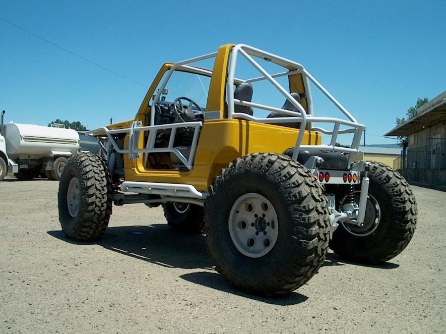
1 Suzuki Samurai Trail Slayer Coil Kit Instructions 1. Remove: (unbolt) *Rear axle, leaf springs, shocks, brake hoses, brake hard lines, e-brake cables, and drive shaft. *Front axle, leaf springs, shocks, brake hoses, brake hard lines, drive shaft, and sway bar. *Steering box, steering shaft, drag link. *Front fenders with grill. *Front and rear bumpers. *Fuel tank. *Radiator and stand / bracket Note: Removal of engine, transmission, and transfer case is NOT required. *Brake proportioning valve and all lines up to the firewall (removal of the two lines across the firewall is NOT required) *All fuel lines. Note: Our build (pictured) will receive all of Trail Tough s premium options so our dis-assembly and prep has gone further than maybe necessary for you. Options include: *2.0 L Engine *3 speed auto transmission *Tub cap *Front / rear cage *Tube front wrap and tube doors *Suspension seats *Ram assist steering *Mighty Kong / Solid t-case mounts *Skid plate *Nerf bars 2. If you have purchased Trail Tough s tub cap. This would be the time to install the cap. (Removal of the rear portion of the body will ease rear subframe install). 3. Using a torch, sawzall, or cut-off disc, remove: *Brake / fuel line mounts, proportioning valve mounts, and rear brake hose mount from inside of right frame rail. *Front bump stop brackets, shock towers, and front brake hose mounts from outside both frame rails. *The inboard leaf spring hangers can be removed, also. 4. Rear Subframe Installation: 1
.")


 instead of cutting square through the tube. See fig. 2 & 3.")


2 Fig. 1 Fig. 2 Fig. 3 * Level your frame front to back according to the center portion of the rails (in the vicinity of the transfer case). Level side to side according to the main cross member. See fig.1 *Measure 24 1/4 from the upper - outside end of each frame rail. This will determine your cut line, so measure and mark carefully. The cut line will end up just barely ahead of the stock bump stop. You could cut the bump stop off of your frame rail if it makes your layout easier. Draw your cut line down the outside square to the ground or frame rail. The original frame tapers out to the rear, your new subframe is parallel so connect your cut lines with a straight line (Across the top of the frame rails) instead of cutting square through the tube. See fig. 2 & 3. *Using a torch, sawzall, or cut-off disc, cut through the rail at the back side of your 24 1/4 cut line. Cut carefully because your line is your only reference. Refer to frame drawing on back page. Fig. 4 Fig. 5 Fig.6 Fig.7 *The forward cross member of the new rear subframe will over lap the ends of the original frame rails. Fit the sub frame in place and level front to back according to the center of the frame. Before tacking in place, remove all rust, paint, or undercoating in the area to be welded. Weld as shown. See fig. 4, 5, 6, Front Subframe installation: *Measure 8 1/8 from the end of each frame rail. This will determine your cut line so measure and mark carefully. This cut line will end up just ahead of the radiator stand brackets. Do NOT cut off these brackets. Draw your cut line square to the frame rail - not the ground, and straight across. See Fig 8 and refer to frame drawing on back page. *Using a torch, sawzall, or cut-off disc cut through the rail at the front side of your 8 1/8 cut line. Cut carefully because your line is your only reference. 2


3 Fig. 8 Fig. 9 Fig. 10 Fig. 11 Fig. 12 Fig. 13 Fig. 14 *The outside gusset plates of the new front subframe will over lap the original frame rails. Fit the subframe in place and level front to back according to the center of the frame. Before tacking in place, remove all rust, paint, or undercoating in the area to be welded. Weld as shown. Refer to Figures 9 through 14 above. 6. Center Subframe Installation: **Note: Front and rear subframes are weld-in ONLY. Center subframe is intended to be bolt-in, however, if you prefer to weld the components to your frame, the choice is yours. *The center subframe is a bolt together assembly consisting of eight main components: 1 Drivers front control arm bracket 1 Passengers front control arm bracket 1 Drivers rear control arm bracket 1 Passengers rear control arm bracket 1 Front drop-out cross member 1 Rear drop-out cross member 2 Sliders 3


 over the frame rails as shown in Fig.")

4 Fig. 15 Fig. 16 Fig. 17 Fig. 18 *Slide the two front control arm brackets (straight tube cross member spuds) over the frame rails. Refer to frame drawing on back page for location relative to front cab mount. Because the frames vary, the 5/8 dimension is just a reference. The brackets should fit tightly over the frame. You may smooth out the under coating in this area but complete removal will only be needed if you plan on welding your brackets. Notice there is one 3/8 thick, two-hole shim not welded at the top of the passenger side bracket. This shim is loose to aid installation over fuel and brake lines which will be reinstalled later. Shim should be in place for drilling. Using four 3/8-16x3 1/2 bolts with flat washers and nylocs, hang the front drop-out crossmember (with tabs) between the two control arm brackets. Leave loose for now. See Fig. 15. *Slide the rear control arm brackets (angled tube crossmember spuds) over the frame rails as shown in Fig.16 Refer to frame drawing for location relative to main crossmember. Because the frames vary, the 2 1/4 dimension is just a reference at this point. The brackets should fit tightly over the frame. You may smooth out the undercoating in this area but complete removal will only be needed if you plan on welding your brackets. Notice there are two 3/8 thick, 2-hole shims not welded at the top of the passenger side bracket. The shims are not welded to aid installation over fuel and brake lines which will be re-installed later. Shims should be in place for drilling. Using four 3/8-16x3 1/2 bolts with flat washers and nylocs, hang the rear drop-out crossmember (without tabs) between the two control arm brackets. Leave loose for now. *Now install the sliders on either side using a 9/16-18x4 bolt and nyloc at each end. You may need to adjust the control arm brackets for proper alignment. Leave bolts loose. Before drilling verify that all four control arm brackets are seated up against the bottom of the frame rails. (Both cross braces of each bracket should hit the bottom of the frame). See Figures 17 and 18. *Clamp the four control arm brackets in place. Transfer punch all 32 holes (inside and outside) or drill (using the control arm brackets as a guide) through the frame using a 25/64 drill bit. *Now remove all brackets and finish (paint, powdercoat, undercoat, etc) your frame and bracketry. 7. Front Axle Bracket Install: ** Requires 1979 to 1985 Toyota pickup complete front end. The factory anti-wrap bar bracket must be removed from the housing. The three small brackets for the steering stabilizer and sway bar should also be removed. ** DO NOT remove the factory leaf spring perches, shock mounts or steering stops!! 4


5 Fig. 19 Fig. 20 Fig. 21 Fig. 22 Fig. 23 Fit passenger side lower control arm bracket (with panhard bracket) up to the housing. Some grinding of the weld on the factory perch may be necessary for proper fit. Bracket should fit flat against and centered over perch and be square to the center line of the housing. Before tack welding in place, remove paint and scale in the area to be welded. Fit driver side in the same manner. Some housings have a short perch on the left side. The supplied 3/8 shim can be tacked to the perch to correctly locate the control arm bracket. See Figures 19 through 23 above. Fig. 24 Fig. 25 The upper control arm bracket sits level on top of the housing to the drivers side of the pumpkin. (It does sit to the passenger side of center) The cutout for the control arm points back. Before tack welding, remove paint and scale. See Figures 24 and 25 above. 5


6 Fig. 26 Fig. 27 Fig. 28 Weld brackets in place. The upper bracket should only be skip welded. See figures 26 through 28 above. Rear Axle ** Requires 1986 to 1995 Toyota pick-up complete rear end with 2 3/8 wide spring perches. The factory e-brake cable bracket and proportioning valve rod bracket could be removed. ** DO NOT remove the factory leaf spring perches or the brake hose / line tabs. Fig. 29 Fig. 30 Fit the drivers side lower control arm bracket up to the housing (shock stud points back and is closest to housing end). Some grinding of the weld on the factory perch may be necessary for proper fit. Bracket should fit flat against and centered over perch and be square to the center line of the housing. Before tacking in place, remove paint and scale in the area to be welded. Fit passenger side in the same manner. Before welding, verify that the shock studs point BACK and are closest to the housing ends. Fig. 31 Fig. 32 Fig. 33 Upper control arm bracket sits centered on top of the housing. Cutout for control arms points forward. Before tacking, remove paint and scale in the area to be welded. 6


, then the crossmembers next.")


7 Fig. 34 Fig. 35 Fig. 36 Fig Assembly *Before installing brackets on your frame you will want to reinstall fuel and brake lines. Your fuel return and vent lines will need to be modified to fit the new rear subframe & fuel tank. *Install the four control arm brackets on your frame using four 3/8-16x3 1/2 bolts with nylocs in each. Notice the passenger side brackets slide over the fuel/brake lines. This is why the upper spacers are not welded in place. Don t forget to install the spacers above the lines (one in the front bracket, two in the rear). Leave bolts loose for now. *Install front and rear drop-out crossmembers using four 3/8-16x3 1/2 bolts with nylocs and flat washers in each. Leave loose. *Install subframe sliders using two 9/16-18x4 bolt (Just slide the bolt through for alignment) Now tighten all 3/8 bolts; through frame bolts first, (torque to 40 ft lbs - do not over tighten), then the crossmembers next. Attach your proportioning valve to the tab on the passenger rear control arm bracket using your original bolt and supplied 6mm flange nuts. See Figures 38 through 40 below. Fig. 38 Fig. 39 Fig. 40 *Rear upper control arms are 1 1/4 diameter x 30 long, rear lowers are 1 3/8 diameter x 30 long. The upper control arms use the only four angled joints in the kit. Preset the center to center length to 34 5/8. The lowers use straight joints, preset to 35 1/2. Install the upper control arms into the upper pocket in the frame bracket using 9/16-18x4 bolts and nylocs. Install two 1/2 USS flatwashers under the heads of these bolts to avoid cramming the end of the bolt into the framerail. The other end fits into the upper control arm bracket on the rear end housing and uses one 9/16-18x7 bolt and nyloc. Notice the angled joints must be oriented the proper way. Install the lower control arms into the lower pocket using the previously installed 9/16-18x4 bolt and nyloc. The other end fits into the lower control arm bracket on the rear end housing using 9/16-18x4 bolts & nylocs. Notice these ends fit sloppy, you can insert one 1/2 USS flatwasher to take up this space now or you can wait until all final adjustments are made. Leave all cross bolts and jam nuts loose for now. See Figures 41 and 42 below. 7


8 Fig. 41 Fig. 42 *Front upper control arm is 1 1/4 diameter x 26 1/2 long, front lowers are 1 3/8 diameter x 26 1/2 long. All three use straight joints. Preset the upper to 31 center to center and the lowers to 32 1/4. NOTE: Preset lengths are only to get in the ballpark. Final adjustments will be made later. Install the upper control arm into the pocket in the front drop-out crossmember and the upper control arm bracket on the front axle housing using 9/16-18x4 bolts & nylocs. Install the lower control arms into the pockets in the front control arm brackets using the previously installed 9/16-18x4 bolts & nylocs. The other end fits into the lower control arm bracket on the front axle housing using 9/16-18x4 bolts & nylocs. Again, these ends fit sloppy. You can insert one 1/2 USS flatwasher to take up this space now or you can wait until all final adjustments are made. Leave all cross bolts and jam nuts loose for now. See figure 43 below. Fig. 43 Fig. 44 *Install the panhard bar (large tie rod ends in both ends) one end in the frame tab, one end in the axle tab. The nuts can be tightened and cotter pinned but leave the jam nuts loose. Preset to 32 1/8 center to center. See figure 44 above. *Install 150 lb. coil springs in the front and 125 lb. coil springs in the rear. Use one coil spring retainer and one 3/8-16x1 1/2 bolt & nyloc at each end of each spring. See Fig. 47. *Install the supplied shock stud through the mount on the rear subframe. Then install the shock (shaft down) first on the lower stud on the axle housing & 5/8-18 jam nyloc and flatwasher, and then the upper using shock stud hardware. The front shocks use 12mm-1.25x60mm long bolts & nylocs at each end. Before installing, you will need to press a steel sleeve into each end of the shocks, choose the one that best fits the 12mm bolt. There is only one per box so you will use leftovers from the rear shocks, too. Do NOT overtighten any of the shock fasteners and make sure all are installed shaft down. See Figures 45 and 46 below. 8


9 Fig. 45 (Front) Fig. 46 (Rear) Fig.47 *Install the brake hose mounting bracket in between the frame and distribution block and bolt hose mounting angle to the other end using original hardware. See Fig. 48. *Install the steering box using new 12mm-1.25 x 90 bolts & nylocs. Reconnect steering shaft by bolting the original steering shaft to our extended flanged steering joint using original hardware. Make sure the steering joints are in phase. See Fig. 49. *Original Toyota steering arms will be replaced with the supplied billet arms using Toyota hardware. Be sure the long arm is on the passenger side. Tie rod installs under the steering arms preset to 46. Drag link installs above arm, preset to 32 1/8, large end to arm and small end to pitman arm. If you have purchased our ram assist steering package, install the clamp over the tie rod before tightening tie rod ends. Otherwise, tighten all nuts and install cotter pins. Leave jam nuts loose. See Fig. 50. *Attach the front brake hose tabs to the small tab on the frame just behind the radiator mounts using original hardware. Install the supplied front brake hoses using original clips. See Fig. 51 Fig. 48 Fig.49 Fig.50 Fig. 51 Original front hard lines can be reformed to fit the new hose location. Rear brake hoses and hard lines have been supplied. Note: Early Samurai s use dual lines, late uses single. Use original clips. *The rear subframe is pre-drilled to accept a Sidekick/Tracker fuel tank from a 1989 to door. 10. Adjustments *After your new Trail Slayer prepped buggy is completely reassembled and set on tires on flat ground, final adjustments can be made. Use the panhard bar to center the front axle. Adjust the length of the rear upper control arms to center the rear axle. **Remember to take the load off of the coil springs & support the vehicle whenever a control arm is to be removed! Now align the front axle to the rear by taking parallel & cross measurements. Adjust the front control arm length to achieve 5 degrees castor angle. Adjust rear control arm lengths to achieve a pinion angle equivalent to the transfer case output. Set toe in front to 1/8 toe in. Adjust the drag link to center the steering box travel. Tighten all cross bolts and jam nuts! Make sure all of the joints are in phase when jam nuts are tightened. 9
10 10
2013+ DODGE RAM " Kit PART# STOP! READ THIS FIRST!
 NOTE: 2013+ DODGE RAM 3500 4" Kit PART# 54346 STOP! READ THIS FIRST! **READ THESE ENTIRE INSTRUCTIONS BEFORE STARTING ANYTHING** or chroming, which can damage the strength and structure of the metal, any
SYNERGY SUSPENSION UNIVERSAL FRONT 3-LINK KIT Version 1.0
 5051 - SYNERGY SUSPENSION UNIVERSAL FRONT 3-LINK KIT Version 1.0 GENERAL NOTES: These instructions are also available on our website; www.synergymfg.com. Check the website before you begin for any updated
READ AND UNDERSTAND ALL INSTRUCTIONS AND WARNINGS PRIOR TO INSTALLATION OF SYSTEM AND OPERATION OF VEHICLE.
 #012456, #012457 Installation Instructions Add-A-Leaf Kit Dodge 3/4 Ton Pickup 4WD READ AND UNDERSTAND ALL INSTRUCTIONS AND WARNINGS PRIOR TO INSTALLATION OF SYSTEM AND OPERATION OF VEHICLE. SAFETY WARNING
2013+ DODGE RAM LIFT KIT PART# STOP! READ THIS FIRST!
 NOTE: 2013+ DODGE RAM 3500 8 LIFT KIT PART# 54324 STOP! READ THIS FIRST! **READ THESE ENTIRE INSTRUCTIONS BEFORE STARTING ANYTHING** or chroming, which can damage the strength and structure of the metal,
Part # Mustang Complete SA CoilOver Kit
 Front Components: 350 S. St. Charles St. Jasper, In. 47546 Ph. 812.482.2932 Fax 812.634.6632 www.ridetech.com Part # 12100210 67-70 Mustang Complete SA CoilOver Kit 1 12103510 Single Adjustable Front CoilOvers
Part # Mustang Complete CoilOver Kit
 Front Components: 1 12103509 Front CoilOvers 1 12102899 Lower StrongArms 1 12103699 Upper StrongArms 350 S. St. Charles St. Jasper, In. 47546 Ph. 812.482.2932 Fax 812.634.6632 www.ridetech.com Part # 12100109
Part # Mustang Complete CoilOver Kit
 Front Components: Part # 12100109 67-70 Mustang Complete CoilOver Kit 1 12103509 Non Adjustable Front CoilOvers 1 12102899 Lower StrongArms 1 12103699 Upper StrongArms Rear Components: 1 12106509 Non Adjustable
6 S-10 Pickup/Jimmy/Blazer Torsion Bar Drop Kit
 92124300 6 S-10 Pickup/Jimmy/Blazer Torsion Bar Drop Kit Thank you for choosing Rough Country for all your suspension needs. Rough Country recommends a certified technician install this system. In addition
4, 6 Suspension System. Ford F250/350 4WD Part#: ,
 Part#: 013411, 013611 4, 6 Suspension System Ford F250/350 4WD 2005-2007 Rev. 071917 491 W. Garfield Ave., Coldwater, MI 49036. Phone: 517-279-2135 E-mail: tech-bds@sporttruckusainc.com Read And Understand
IFS Eliminator Kit,
 IFS Eliminator Kit, 110001-1 IFS Eliminator Kit Contents: Front Leaf Springs (choice 3", 4", or 5") 1.0 High Steer Crossover Steering Kit 1.0 Frame Tube Jig Kit 1.0 Steering Stabilizer Kit 1.0 U-bolt Flip
INSTRUCTION S G-Comp Front Suspension: Chevy Nova Speedway Motors, Inc. 2017
 INSTRUCTION S 350-100 G-Comp Front Suspension: 62-67 Chevy Nova Speedway Motors, Inc. 2017 Kit Contents: 91035700 G-Comp Bare Subframe 350101 G-Comp Support Tubes 91035702 G-Comp Front Subframe Hardware
INSTALLATION INSTRUCTIONS 64 ½ - 70 SUPERRIDE II INDEPENDENT FRONT SUSPENSION BX-350 FOR COYOTE AND MOD ENGINES
 INSTALLATION INSTRUCTIONS 64 ½ - 70 SUPERRIDE II INDEPENDENT FRONT SUSPENSION BX-350 FOR COYOTE AND MOD ENGINES Please read these instructions completely before starting your installation. Assemble suspension
Installation Instructions
 Installation Instructions Jeep TJ Long Arm Suspension System 1997-2002 JEEP TJ 4WD 6 1997-2002 JEEP TJ 4WD FTS24002 & BK / FTS24003 & BK / FTS44002 & BK PARTS LIST FTS24002BK Jeep TJ 6' Box Kit 1 FTS24003BK
INSTALLATION INSTRUCTIONS CHEVY C-10 4-Link Rear End
 INSTALLATION INSTRUCTIONS 73-87 CHEVY C-10 4-Link Rear End Please read these instructions completely before starting your installation. Assemble suspension on vehicle before powder-coating to ensure proper
67 [ ] OR [ ] REAR BRACKETS BARS Shocks Includes: Includes: Includes: Includes:
![67 [ ] OR [ ] REAR BRACKETS BARS Shocks Includes: Includes: Includes: Includes:](/thumbs/76/73590788.jpg "67 [ ] OR [ ] REAR BRACKETS BARS Shocks Includes: Includes: Includes: Includes:") 1967-1969 Firebird Mini Tub 4-Link Install Instructions 1-866-925-1101 www.totalcostinvolved.com CHECK ALL PARTS INCLUDED IN THIS KIT TO THE PARTS LIST BEFORE INSTALLATING OF THE KIT. IF ANY PIECES ARE
1967-1969 Firebird Mini Tub 4-Link Install Instructions 1-866-925-1101 www.totalcostinvolved.com CHECK ALL PARTS INCLUDED IN THIS KIT TO THE PARTS LIST BEFORE INSTALLATING OF THE KIT. IF ANY PIECES ARE
PPM-8022 / PPM-8042 JEEP JK STAGE 2 SYNERGY SUSPENSION SYSTEM Version 1
 POLY PERFORMANCE MFG. 870 INDUSTRIAL WAY, SAN LUIS OBISPO, CA (805) 242-0397 PPM-8022 / PPM-8042 JEEP JK STAGE 2 SYNERGY SUSPENSION SYSTEM Version 1 GENERAL NOTES: These instructions are also available
INSTALLATION INSTRUCTIONS QA1 P/N x400, x500, x600, x400, x500, x F100 Front Coil-over Suspension System
 INSTALLATION INSTRUCTIONS QA1 P/N 52620-x400, 52620-x500, 52620-x600, 52621-x400, 52621-x500, 52621-x600 65-72 F100 Front Coil-over Suspension System TOOLS AND SUPPLIES REQUIRED Floor Jack Two (2) Jack
PPM-8023 / PPM-8043 JEEP JK SYNERGY STAGE 3 SUSPENSION SYSTEM Version 1
 SYNERGY MFG. 870 INDUSTRIAL WAY, SAN LUIS OBISPO, CA (805) 242-0397 PPM-8023 / PPM-8043 JEEP JK SYNERGY STAGE 3 SUSPENSION SYSTEM Version 1 GENERAL NOTES: These instructions are also available on our website;
»Product» Safety Warning
 J1455, J1456 Installation Instructions 1984-2001 Jeep Cherokee XJ 4.5 Suspension Lift Read and understand all instructions and warnings prior to installation of product and operation of vehicle. Zone Offroad
Camaro Torque Arm Install Instructions
 1967-1969 Camaro Torque Arm Install Instructions 1-800-984-6259 www.totalcostinvolved.com 67 [429-4202-00] OR 68-69 [429-4202-00] REAR BRACKETS BARS Shocks Includes: Includes: Includes: Includes: 1 REAR
HEIDTS RF-110. INSTALLATION INSTRUCTIONS Fairlane Comet Rear 4-Link
 HEIDTS RF-110 INSTALLATION INSTRUCTIONS 66-67 Fairlane 66-67 Comet Rear 4-Link Please read these instructions completely before starting your installation. Remember the basic rule for a successful installation:
Part # C-10 Level 2 Complete Air Suspension System
 350 S. St. Charles St. Jasper, In. 47546 Ph. 812.482.2932 Fax 812.634.6632 www.ridetech.com Part # 11340299 63-70 C-10 Level 2 Complete Air Suspension System Front Components: 1 11330999 Front CoolRide
INSTALLATION INSTRUCTIONS
 INSTALLATION INSTRUCTIONS 2005-2012 Nissan Xterra/Frontier / Pathfinder PART NUMBERS: NP17500, NP17525, NP17550 FRONTIER PARTS & CORRESPONDING HARDWARE LIST XTERRA PATHFINDER ABOVE LISTED 1/2 Metal Lock
Part # Chevy C-10 Rear CoolRide Kit w/ StrongArms
 Components: 2 90006781 267c air spring 350 S. St. Charles St. Jasper, In. 47546 Ph. 812.482.2932 Fax 812.634.6632 www.ridetech.com Part # 11336799 63-72 Chevy C-10 Rear CoolRide Kit w/ StrongArms 1 90000626
INSTALLATION INSTRUCTION 88146
 INSTALLATION INSTRUCTION 88146 Rev H FOR RANCHO SUSPENSION SYSTEM RS6547: 4WD SUBURBAN/YUKON XL, 4WD TAHOE/YUKON, & 4WD AVALANCHE READ ALL INSTRUCTIONS THOROUGHLY FROM START TO FINISH BEFORE BEGINNING
CSS-C CHEVROLET SUBURBAN & TAHOE WD AND 2WD CHEVROLET AVALANCHE WD AND 2WD 6-8 SUSPENSION LIFT KIT
 14385 Veterans Way Moreno Valley, CA 92553 Phone: (951) 571-0212 Fax: (951) 571-0215 WWW.CSTSUSPENSION.COM CSS-C3-3 2000-2006 CHEVROLET SUBURBAN & TAHOE 1500 4WD AND 2WD 2002-2006 CHEVROLET AVALANCHE 1500
Alignment Spec. Power Rack & Pinion: 5 degrees positive Camber 0 degrees Toe-In 1/32
 333-TCIE237 1967-1969 Chevy Camaro Front Suspension 1968-1972 Chevy Nova Front Suspension 1967-1969 Pontiac Firebird Front Suspension 1-800-984-6259 www.totalcostinvolved.com 1967-1969 Chevy Camaro Front
Technical Support Line: (952) Hanover Ave. Lakeville, MN
 Hanover Ave. Lakeville, MN") Technical Support Line: (952) 985-5675 Email: Sales@QA1.net 21730 Hanover Ave. Lakeville, MN 55044 www.qa1.net INSTALLATION INSTRUCTIONS QA1 1967-1979 Mopar A-Body Rear 6 link Conversion System QA1 p/n
Technical Support Line: (952) 985-5675 Email: Sales@QA1.net 21730 Hanover Ave. Lakeville, MN 55044 www.qa1.net INSTALLATION INSTRUCTIONS QA1 1967-1979 Mopar A-Body Rear 6 link Conversion System QA1 p/n
Chevy Nova Pro-Touring Front Suspension Installation Instructions
 1962-1967 Chevy Nova Pro-Touring Front Suspension Installation Instructions 1-800-984-6259 www.totalcostinvolved.com 1 Pro-Touring Clip A-Arm Assembly Sway Bar Assembly Fender Panel Kit 8 7/16-20 * 1 ¼
INSTALLATION GUIDE. 3 Dualsport suspension. ram truck 2500/3500. AEV30243AA Last Updated: 04/10/15
 3 Dualsport suspension AEV30243AA Last Updated: 04/10/15 ram truck 2500/3500 INSTALLATION GUIDE PLEASE READ BEFORE YOU START TO GUARANTEE A QUALITY INSTALLATION, WE RECOMMEND READING THESE INSTRUCTIONS
KIT # CSS-C SUSPENSION LIFT KIT
 14385 Veterans Way Moreno Valley, CA 92553 Phone: (951) 571-0212 Fax: (951) 571-0215 2001-2010 CHEVROLET SILVERADO 1500 AND 2500 HD 4WD AND 2WD PICK-UP 1999-2010 CHEVY 2500 4WD PICK-UPS 2001-2010 2500
AEV30243AJ Last Updated: 11/14/17. 3 Dualsport front suspension ram truck 2500/3500 INSTALLATION GUIDE
 AEV30243AJ Last Updated: 11/14/17 3 Dualsport front suspension ram truck 2500/3500 INSTALLATION GUIDE PLEASE READ BEFORE YOU START TO GUARANTEE A QUALITY INSTALLATION, WE RECOMMEND READING THESE INSTRUCTIONS
»Product» Safety Warning
 J1457, J1458 Installation Instructions 1984-2001 Jeep Cherokee XJ 4.5 Suspension Lift Read and understand all instructions and warnings prior to installation of product and operation of vehicle. Zone Offroad
Detroit Speed, Inc. Mini-Tub Kit Chevy Nova, Oldsmobile Omega, Pontiac Ventura P/N: &
 Detroit Speed, Inc. Mini-Tub Kit 1968-74 Chevy Nova, Oldsmobile Omega, Pontiac Ventura P/N: 041207 & 041208 Item Component Quantity 1 DSE Mini Tubs 1968-74 X-Body 2 2 Rear Upper Shock Crossmember 1 3 Upper
READ AND UNDERSTAND ALL INSTRUCTIONS AND WARNINGS PRIOR TO INSTALLATION OF SYSTEM AND OPERATION OF VEHICLE.
 #021700, 021701 7 Suspension System 2000-2004 Chevy/GMC 1500 2wd Extended Cab w/ Front Coil Springs READ AND UNDERSTAND ALL INSTRUCTIONS AND WARNINGS PRIOR TO INSTALLATION OF SYSTEM AND OPERATION OF VEHICLE.
Chevrolet 3100 IFS Kit
 1947-54 Chevrolet 3100 IFS Kit Congratulations on your purchase on what we believe is the finest IFS kit available for 1947-54 Chevrolet pickups with stock frames. We have invested many hours into designing
FITMENT BACKCOUNTRY 2.0-6" LIFT 6" Systems Require a Drop Pitman Arm, "T" Style Steering & Driveshaft to be lengthened 2"
 PLEASE VISIT: Forums.CarliSuspension.com Troubleshooting advice or to download an electronic copy of this document. FITMENT BACKCOUNTRY 2.0-6" LIFT 6" Systems Require a Drop Pitman Arm, 08.5+ "T" Style
2014+ DODGE RAM LIFT KIT PART# STOP! READ THIS FIRST!
 NOTE: 2014+ DODGE RAM 2500 8 LIFT KIT PART# 54320 STOP! READ THIS FIRST! **READ THESE ENTIRE INSTRUCTIONS BEFORE STARTING ANYTHING** or chroming, which can damage the strength and structure of the metal,
RAM LIFT KIT PART# STOP! READ THIS FIRST!
 NOTE: 2014-2016 RAM 2500 4 LIFT KIT PART# 54340 STOP! READ THIS FIRST! **READ THESE ENTIRE INSTRUCTIONS BEFORE STARTING ANYTHING** or chroming, which can damage the strength and structure of the metal,
DO NOT GRIND ANY WELDS! DO NOT QUENCH WELDS WITH WATER OR OIL. ALLOW TO AIR COOL.
 1 READ FIRST! PLEASE READ THROUGH ALL OF THE INSTRUCTIONS AND ENSURE THAT YOU UNDERSTAND THEM. BE SURE THAT YOU HAVE ALL THE REQUIRED GSI COMPONENTS, BASIC TOOLS, AND SKILLS. CUTTING THIS KIT REQUIRES
INSTRUCTION S G-Comp Front Suspension: Chevy Camaro Speedway Motors, Inc Kit Contents:
 INSTRUCTION S 350-500 G-Comp Front Suspension: 70-81 Chevy Camaro Speedway Motors, Inc. 2017 Kit Contents: 350500.1 G-Comp Subframe, Camaro 350500.2 G-Comp Sway Bar Kit, Camaro 350500.3 Hardware Kit, G-Comp
»Product» Safety Warning
 #F2622 Installation Instructions 1997-2003 Ford F-150 4WD 6" Suspension System Read and understand all instructions and warnings prior to installation of product and operation of vehicle. Zone Offroad
INSTALLATION INSTRUCTION 88581
 INSTALLATION INSTRUCTION 88581 FOR RANCHO SUSPENSION SYSTEM RS6581B: DODGE RAM READ ALL INSTRUCTIONS THOROUGHLY FROM START TO FINISH BEFORE BEGINNING INSTALLATION Rev C IMPORTANT NOTES! WARNING: This suspension
DO NOT GRIND ANY WELDS
 1 READ FIRST! PLEASE READ THROUGH ALL OF THE INSTRUCTIONS AND ENSURE THAT YOU UNDERSTAND THEM. BE SURE THAT YOU HAVE ALL THE REQUIRED GSI COMPONENTS, BASIC TOOLS, AND SKILLS. CUTTING THIS KIT REQUIRES
INSTALLATION INSTRUCTION 88051
 INSTALLATION INSTRUCTION 88051 For Rancho Suspension System RS6551: Chevrolet 2500 Suburban & 2500 Avalanche READ ALL INSTRUCTIONS THOROUGHLY FROM START TO FINISH BEFORE BEGINNING INSTALLATION Rev C IMPORTANT
CSS-C SUSPENSION LIFT KIT
 115 W. La Cadena Dr. Ste 100 Riverside, CA 92501 (951) 328-9902 phone (951) 328-9908 fax 2000-2006 CHEVROLET SILVERADO 1500 4WD CSS-C3-2 6-8 SUSPENSION LIFT KIT WARNING: CALIFORNIA SUPERTRUCKS RECOMMENDS
1964 1/2-70 Mustang Torque Arm Rear Suspension Installation Instructions
 1964 1/2-70 Mustang Torque Arm Rear Suspension Installation Instructions 1-800-984-6259 www.totalcostinvolved.com Version 2 (c) 2008 Total Cost Involved Engineering, Inc. All Rights Reserved. Page 1 of
CHECK ALL PARTS INCLUDED IN THIS KIT TO THE PARTS LIST BEFORE INSTALLATION. IF ANY PIECES ARE MISSING, PLEASE CONTACT: TOTAL COST INVOLVED
 333-TCIE237 1967-1969 Chevy Camaro Front End, 1968-1972 Chevy Nova Front End 1967-1969 Pontiac Firebird Front End Suspension Installation Instructions 1-855-693-1259 www.totalcostinvolved.com CHECK ALL
4 & 6 4-Link Suspension Systems. Ford Super Duty 4WD Part#: ,
 Part#: 013013, 013014 4 & 6 4-Link Suspension Systems Ford Super Duty 4WD 2011-2016 Rev. 051817 491 W. Garfield Ave., Coldwater, MI 49036. Phone: 517-279-2135 E-mail: tech-bds@sporttruckusainc.com Read
Part # Mustang Complete NA CoilOver Kit
 Front Components: 350 S. St. Charles St. Jasper, In. 47546 Ph. 812.482.2932 Fax 812.634.6632 www.ridetech.com Part # 12090109 64-66 Mustang Complete NA CoilOver Kit 1 12093509 Non Adjustable Front CoilOvers
Chrysler A-Body Tubular A-Arms Installation Instructions A-ARM INSTALLATION
 1967-1976 Dodge Demon 1112 67-72 Chrysler A-Body Tubular A-Arms Installation Instructions Thank you for your purchase of this Hotchkis Performance product. Your A-Arm set was designed with the performance
Tools Needed: Class 8.8 Class MM 55ft/lbs 75ft/lbs 14MM 85ft/lbs 120ft/lbs 16MM 130ft/lbs 165ft/lbs 18MM 170ft/lbs 240ft/lbs
 921788000 JEEP JK 6 LONGARM Rough Country recommends a certified technician install this system. In addition to these instructions, professional knowledge of disassemble/reassembly procedures as well as
INSTALLATION INSTRUCTION 88148
 INSTALLATION INSTRUCTION 88148 Rev C For Rancho Suspension Systems RS6548, RS6549 & RS6550: GM 2500HD, 2500, and 1500HD Trucks READ ALL INSTRUCTIONS THOROUGHLY FROM START TO FINISH BEFORE BEGINNING INSTALLATION
2008 & Newer Ford F-350 Chassis Cab 4-Link Rear Installation Instructions
 KLM18100 2686 Highway 92 - Oskaloosa, IA 52577 phone: 641.673.0468 - fax: 641.673.4168 2008 & Newer Ford F-350 Chassis Cab 4-Link Rear Installation Instructions Installation 1. Before doing anything, measure
6 Suspension System. Dodge wd Part#:
 Part#: 012622 6 Suspension System Dodge 2500 4wd 2009-2013 Rev. 010218 491 W. Garfield Ave., Coldwater, MI 49036. Phone: 517-279-2135 E-mail: tech-bds@sporttruckusainc.com Read And Understand All Instructions
DODGE RAM WHEEL DRIVE DODGE RAM WHEEL DRIVE FTS /2 LIFT BOX KIT
 2000-2001 DODGE RAM 1500 4 WHEEL DRIVE 1994-2002 DODGE RAM 2500 4 WHEEL DRIVE FTS3420 5 1/2 LIFT BOX KIT FTS3420BK 1994-99 DODGE RAM 4WD FT44219 Hdwr Sub-Assembly Kit Qua. Part # Description Qua. Part
USE THE PARTS LIST BELOW TO MAKE SURE YOUR KIT IS COMPLETE BEFORE INSTALLATION. IF ANY PIECES ARE MISSING, PLEASE CONTACT:
 1962-1967 Chevy Nova Pro-Touring Front Suspension Installation Instructions Tech line: 1-855-693-1259 www.totalcostinvolved.com Read and understand these instructions before starting any work! USE THE
Suspension System RS6582B
 Suspension System RS6582B Tahoe/Yukon READ ALL INSTRUCTIONS THOROUGHLY FROM START TO FINISH BEFORE BEGINNING INSTALLATION IMPORTANT NOTES! WARNING: This suspension system will enhance the off-road performance
6 Suspension System. Dodge wd Part#: &
 Part#: 012621 & 012631 6 Suspension System Dodge 2500 4wd 2008-2009 Rev. 010218 491 W. Garfield Ave., Coldwater, MI 49036. Phone: 517-279-2135 E-mail: tech-bds@sporttruckusainc.com Read And Understand
AEV30213AF Last Updated: 05/24/18. jk wrangler dualsport sc suspension right hand drive INSTALLATION GUIDE
 AEV30213AF Last Updated: 05/24/18 jk wrangler 3.5 4.5 dualsport sc suspension right hand drive INSTALLATION GUIDE PLEASE READ BEFORE YOU START TO GUARANTEE A QUALITY INSTALLATION, WE RECOMMEND READING
Part # Galaxie Air Suspension System
 350 S. St. Charles St. Jasper, In. 47546 Ph. 812.482.2932 Fax 812.634.6632 www.ridetech.com Part # 12160298 60-64 Galaxie Air Suspension System Front Components: 1 12162401 Master Series Single Adjustable
Read and understand all instructions and warnings prior to installation of system and operation of vehicle.
 102 S. Michigan Ave., Coldwater, MI 49036 Phone: 517-279-2135 Web/live chat: www.bds-suspension.com E-mail: tech@bds-suspension.com Part#: 014443 Product: 4.5" Long Arm Suspension System Application: 1987-2001
1 M-3000-H4 F150 4X4 Lowering Kit
 READ INSTRUCTIONS COMPLETELY THROUGH BEFORE STARTING. IT IS RECOMMENDED THAT INSTALLATION BE DONE BY A QUALIFIED MECHANIC. REPLACE ALL STOCK PARTS THAT ARE DAMAGED OR WORN. ALWAYS WEAR EYE PROTECTION.
INSTALLATION INSTRUCTIONS CHEVROLET NOVA (NVR-301) INDEPENDENT REAR SUSPENSION
 INDEPENDENT REAR SUSPENSION") INSTALLATION INSTRUCTIONS 68-74 CHEVROLET NOVA (NVR-301) INDEPENDENT REAR SUSPENSION Please read these instructions completely before starting your installation. Assemble suspension on vehicle before powder-coating
INSTALLATION INSTRUCTIONS 68-74 CHEVROLET NOVA (NVR-301) INDEPENDENT REAR SUSPENSION Please read these instructions completely before starting your installation. Assemble suspension on vehicle before powder-coating
Pro/Series 2000 Tubular A-Arm Front Suspension
 11 Mennonite Church Road Spring City, PA 19475 (610) 948-7303 Installation Instructions Pro/Series 2000 Tubular A-Arm Front Suspension (Pinto-Style) CAUTION!!! The most important requirement for a successful
AEV30243AK Last Updated: 05/01/18. 3 Dualsport front suspension ram truck 2500/3500 INSTALLATION GUIDE
 AEV30243AK Last Updated: 05/01/18 3 Dualsport front suspension ram truck 2500/3500 INSTALLATION GUIDE PLEASE READ BEFORE YOU START TO GUARANTEE A QUALITY INSTALLATION, WE RECOMMEND READING THESE INSTRUCTIONS
INSTALLATION INSTRUCTIONS 89551
 INSTALLATION INSTRUCTIONS 89551 For Rancho Suspension System RS66551B: Ford F250, F350 Super Duty 4x4 DIESEL ONLY (Single Rear Wheels Only With or Without Auxiliary Spring). (WILL NOT WORK ON GAS ENGINES
INSTALLATION INSTRUCTIONS QA1 P/N R , R , R R , R , R F100 Rear Coil-over Conversion System
 INSTALLATION INSTRUCTIONS QA1 P/N R120-170, R120-200, R120-250 R220-170, R220-200, R220-250 65-72 F100 Rear Coil-over Conversion System TOOLS AND SUPPLIES REQUIRED Floor Jack Two (2) Jack Stands Drill
INSTALLATION INSTRUCTIONS
 INSTALLATION INSTRUCTIONS ----1075 North Ave. Sanger, CA 93657-3539 toll free: 800-445-3767 web: www.belltechcorp.com---- 6420 SHACKLE & HANGER KIT FORD F-350 Congratulations! You were selective enough
63162K 2015 Chevrolet Colorado 4WD Leveling Kit w/ 1 Rear Lift Kit
 PRO COMP SUSPENSION 63162K 2015 Chevrolet Colorado 4WD Leveling Kit w/ 1 Rear Lift Kit This document contains very important information that includes warranty information and instructions for resolving
FAX
 INSTALLATION INSTRUCTIONS 6090 Air Suspension Kit (pat. pending) 1999-2006 Tahoe, Suburban, Avalanche, Yukon Thank you for purchasing a quality Hellwig Product. PLEASE READ THIS INSTRUCTION SHEET COMPLETELY
Sport Sway Bar Kit Mustang
 Sport Sway Bar Kit 22102 2005 Mustang Installation of Hotchkis Front Sway Bar 1F Raising Vehicle Securely block the rear wheels of the vehicle. Use a jack to lift up the front of the vehicle and use jack
INSTALLATION INSTRUCTION 88094
 INSTALLATION INSTRUCTION 88094 FOR RANCHO SUSPENSION SYSTEM RS6594B 4WD & 2WD NISSAN TITAN READ ALL INSTRUCTIONS THOROUGHLY FROM START TO FINISH BEFORE BEGINNING INSTALLATION Rev D IMPORTANT NOTES! WARNING:
WJ 6.5" Long Travel PART #: RK-605LT-WJ APPLICATION: WJ
 Rusty s Off-Road Products 7161 Steele Station Road Rainbow City, AL 35906 Phone: (256) 442-0607 FAX: (256) 442-0017 Web Site: www.rustysoffroad.com WJ 6.5" Long Travel PART #: RK-605LT-WJ APPLICATION:
Part # GM F Body Complete CoilOver System
 350 S. St. Charles St. Jasper, In. 47546 Ph. 812.482.2932 Fax 812.634.6632 www.ridetech.com Part # 11170109 70-81 GM F Body Complete CoilOver System Front Components: 1 11173509 Front Fixed Valving CoilOvers
Carli Suspension Front Instructions
 Carli Suspension Front Instructions 94-08 DODGE 2500-3500 4X4 SUSPENSION SYSTEM Note: Prior to installation, carefully inspect the vehicle=s steering and drive train components. Be sure to check ball joints,
Superlift 4 lift system for JEEP CHEROKEE XJ with coil spring suspension INSTALLATION INSTRUCTIONS
 FORM #5140.01-102605 PRINTED IN U.S.A. PAGE 1 OF 12 INTRODUCTION Superlift 4 lift system for 1984-2001 JEEP CHEROKEE XJ with coil spring suspension INSTALLATION INSTRUCTIONS Installation requires a professional
TOYOTA FJ CRUISER 6 SUSPENSION KIT
 92177000 TOYOTA FJ CRUISER 6 SUSPENSION KIT Thank you for choosing Rough Country for your suspension needs. Rough Country recommends a certified technician installs this system. In addition to these instructions,
»Product» Safety Warning
 T2502 Installation Instructions 2007-2017 Toyota Tundra 4wd 5" Suspension System Read and understand all instructions and warnings prior to installation of product and operation of vehicle. Zone Offroad
4.5 Suspension System. Jeep TJ BDS PART # Ultimate; # Standard
 BDS PART #014460 Ultimate; #014440 Standard 491 W. Garfield Ave., Coldwater, MI 49036. Phone: 517-279-2135 Web/live chat: www.bds-suspension.com. E-mail: tech-bds@sporttruckusainc.com 4.5 Suspension System
# " Suspension System Jeep Wrangler TJ. 102 S. Michigan Avenue Coldwater, MI
 #014452 4.5" Suspension System Jeep Wrangler TJ Read and understand all instructions and warnings prior to installation of system and operation of vehicle. SAFETY WARNING BDS Suspension Co. recommends
6 and 8 Long Travel Suspension System. Dodge Ram Part#:
 Part#: 012801 6 and 8 Long Travel Suspension System Dodge Ram 2500 2003-2012 Rev. 092617 491 W. Garfield Ave., Coldwater, MI 49036. Phone: 517-279-2135 E-mail: tech-bds@sporttruckusainc.com Read And Understand
»Product» Safety Warning
 J1300, J1301 Installation Instructions 1997-2006 Jeep TJ 3 Suspension Lift Read and understand all instructions and warnings prior to installation of product and operation of vehicle. Zone Offroad Products
Part # Mustang Complete HQ Series Coil-Over Kit
 350 S. St. Charles St. Jasper, In. 47546 Ph. 812.482.2932 Fax 812.634.6632 www.ridetech.com Front Components: Part # 12090210 64-66 Mustang Complete HQ Series Coil-Over Kit 1 12093509 HQ Series Front Coil-Overs
Read and understand all instructions and warnings prior to installation of system and operation of vehicle.
 491 W. Garfield Ave., Coldwater, MI 49036 Phone: 517-279-2135 Web/live chat: www.bds-suspension.com E-mail: tech@bds-suspension.com Part#: 014444 Product: 4.5" Suspension System Application: Jeep Cherokee
Rusty's XJ Competition 4-Link Suspension System RK-CS10-XJ INSTALLATION INSTRUCTIONS
 Rusty's XJ Competition 4-Link Suspension System RK-CS10-XJ INSTALLATION INSTRUCTIONS Last Revised: 5/24/2017 Introduction: Rusty s recommends that this installation be performed by a certified automotive
22004 INSTALLATION INSTRUCTIONS INSTALLATION 07-UP JEEP JK 2/4 DOOR REAR COILOVER CONVERSION SYSTEM COMPONENTS INCLUDED HARDWARE INCLUDED
 7929 Lincoln Ave. Riverside, CA 92504 Phone: 951.689.ICON Fax: 951.689.1016 PART # 22004 22004 INSTALLATION INSTRUCTIONS DESCRIPTION 10-13-2015 REV.B 07-UP JEEP JK 2/4 DOOR REAR COILOVER CONVERSION SYSTEM
INSTALLATION INSTRUCTION 88088
 INSTALLATION INSTRUCTION 88088 For Rancho Suspension Systems RS6588 & RS6589: FORD F-150 READ ALL INSTRUCTIONS THOROUGHLY FROM START TO FINISH BEFORE BEGINNING INSTALLATION Rev B IMPORTANT NOTES! WARNING:
JEEP JK 4 LONGARM. Tools Needed: Thank you for choosing Rough Country for your suspension needs.
 921786000 Thank you for choosing Rough Country for your suspension needs. JEEP JK 4 LONGARM Rough Country recommends a certified technician install this system. In addition to these instructions, professional
Super Duty Front Air Bag Installation Instructions
 2005-2010 Super Duty Front Air Bag Installation Instructions Congratulations! You have just purchased the best engineered, highest quality front air suspension kit available on the market for your 2005-2010
»Product» Safety Warning
 J1400, J1401 Installation Instructions 1997-2006 Jeep TJ 4 Suspension Lift Read and understand all instructions and warnings prior to installation of product and operation of vehicle. Zone Offroad Products
Read and understand all instructions and warnings prior to installation of system and operation of vehicle.
 102 S. Michigan Ave., Coldwater, MI 49036 Phone: 517-279-2135 Web/live chat: www.bds-suspension.com E-mail: tech@bds-suspension.com Part#: 014450 Product: 4.5" Suspension System Application: 1987-1995
AEV30213AH Last Updated: 04/28/17. jk wrangler dualsport sc suspension INSTALLATION GUIDE
 AEV30213AH Last Updated: 04/28/17 jk wrangler 3.5 4.5 dualsport sc suspension INSTALLATION GUIDE PLEASE READ BEFORE YOU START TO GUARANTEE A QUALITY INSTALLATION, WE RECOMMEND READING THESE INSTRUCTIONS
8" 4-LINK SUSPENSION SYSTEM. Ford Super Duty 4WD Part#:
 Part#: 013813 8" 4-LINK SUSPENSION SYSTEM Ford Super Duty 4WD 2011-2016 Rev. 051817 491 W. Garfield Ave., Coldwater, MI 49036. Phone: 517-279-2135 E-mail: tech-bds@sporttruckusainc.com Read And Understand
AEV JK Standard Suspensions Installation Instructions
 AEV JK Standard Suspensions Installation Instructions 3.0 and 4.0 suspension systems designed for: 2007-current Jeep JK Wrangler and Unlimited models including Rubicon packages Kit Part Numbers Vehicle
INSTALLATION INSTRUCTIONS 88511
 INSTALLATION INSTRUCTIONS 88511 For Suspension System RS6511: Ford Super Duty Requires coil spring kit RS80117 or RS80119 for a complete installation READ ALL INSTRUCTIONS THOROUGHLY FROM START TO FINISH
Part # Chevy Level 2 CoilOver Suspension Package Two Piece Frame
 350 S. St. Charles St. Jasper, In. 47546 Ph. 812.482.2932 Fax 812.634.6632 www.ridetech.com Part # 11030210 55-57 Chevy Level 2 CoilOver Suspension Package Two Piece Frame Front Components: 1 11013510
OVER THE KNUCKLE 1-TON STEERING INSTALLATION INSTRUCTIONS
 OVER THE KNUCKLE 1-TON STEERING INSTALLATION INSTRUCTIONS TOOLS NEEDED Grinder with cutoff wheel, sawzall, cutting torches, or a plasma cutter Welder (for optional sway bar mounts) Hand drill with a ½
INSTALLATION INSTRUCTION 88578
 INSTALLATION INSTRUCTION 88578 For Rancho Suspension System RS6579B: 4WD Dodge 1500 & 2500 READ ALL INSTRUCTIONS THOROUGHLY FROM START TO FINISH BEFORE BEGINNING INSTALLATION Rev E IMPORTANT NOTES! WARNING:
Detroit Speed, Inc. QUADRA Link Rear Suspension Chevy II P/N:
 Detroit Speed, Inc. QUADRA Link Rear Suspension 1962-1967 Chevy II P/N: 041707 Detroit Speed, Inc. QUADRAlink is a great way to upgrade from original leaf spring suspension. Unlike our competitors, Detroit