4405-RA 4405-R 4405-RA 4405-R S
|
|
|
- Aldous Phillips
- 5 years ago
- Views:
Transcription

1 ACCESSORIES Page 34 Master Parts Breakdowns Updated Feb. 1st 2006

2 Master Parts Breakdowns Updated Feb. 1st 2006 Page 35

3 This tool is designed to operate on 90 psig (6.2 bar) maximum air pressure with 1/4 (8 mm) hose. Do not use a grinder without recommended wheel guard. Do not use any wheel for which the operating speed listed is lower than the actual free speed of the Grinder. SAFETY 1.Before operation check spindle speed with a tachometer. If the RPM exceeds the rated speed stamped on tool, servicing is required. 2. Inspect grinding wheels for bends, chips, nicks, cracks or severe wear. If the wheel has any of these, or has been soaked in liquids do not use. On brushes check for loose wires that may fly off in operation. 3. Start new grinding wheels under a steel bench. Run at full throttle for one minute.defective wheels usually come apart immediately.when starting a cold wheel apply to work slowly, allow wheel to warm gradually. 4. Model 4405RA grinders equipped with collets are intended for mounted wheels,points and carbide burrs. They are not guarded for type 1 wheels. If you have a type 1 wheel application,please purchase a guard (4504,4505,etc.) 5. The Model 4405RA Grinders are equipped with a Spiral-Cool Pad from the manufacturer. A guard is not needed for :a.) mounted wheels two inches (50 mm) or smaller; b.) grinders used for internal work, while within the work being ground. 6. At least one-half of the mandrel length (i.e. mounted wheel, burr, etc.) must be inserted into the collet. Secure collet chuck tightly. 7.Safety levers are available from the manufacturer.(402-26). 8. Before mounting or removing a wheel, disconnect grinder from air supply. The wheel should fir properly on arbor, do not use bushings or wheel flanges to adapt a wheel to any arbor unless recommended by the manufacturer. (Wheel flanges should be at least 1/3 the diameter of the grinding wheel.) 9. Wear safety goggles and other protective clothing. Continuous exposure to vibration may cause injury to your hands and arms.(see regulations.) 10. Properly maintained air tools are less likely to fail or cause accidents. If tool produces an unusual sound or vibrations repair immediately. DISASSEMBLY PLEASE NOTE: The brass spacers that were installed by the factory are necessary for this tool to operate efficiently. When disassembling this tool examine how spacers are arranged. They must be installed exactly the same way. Failure to do this will cause improper gear spacing, which causes pre-mature tool failure. 1.Disconnect air & remove all wheels and accessories. 2. Remove handle (404-40). Secure anglehead in vise on dead handle boss. Unscrew and remove case( ) Never squeeze anglehead(404-1) in vise. This will distort bearings and ruin gear alignment. 3. Remove deflector (410-G- 17-S). 4. Pull motor from right angle head. Be careful to note location of shims. 5. Remove snap ring (404-39),wafer(404-38),O-ring(594016), and snap ring (592016).(Some of these may not be present). 6. Install brass or aluminum jaws in vise. Grasp the O.D. of cylinder(400-2-g)and end plate(404-19). Using a 3/16 punch, tap spindle out rear bearing (404-9) 7.Remove cylinder, blades(400-6). 8. With rotor (400-5) still on spindle (404-14), grasp the rotor in vise snugly and remove pinion gear(404-10). 8. Remove rotor(400-5) Remove key and front thrust plate(400-7). 9. Press bearing (400-G-11) off of spindle. 10. Secure angle head in vise and unscrew cap (404-2). 11. Remove from vise and tap on spindle with a plastic hammer The spindle assembly and spring washers (404-6) will slide out. 11. Remove screw (591028). Remove Snap ring(404-8). Remove spacer( )and gear(405-10) as well as (404-4)key. Press or tap out spindle( ) from bearing (404-7). of bearing cap until free of bearing (404-3). Note position of shims. Using a 9/64 T-Handle hex wrench unscrew (591028) screw. [(NOTE:Some older models have a snap ring(405-16) to be removed instead of a screw)] 13. Press bearing (404-3) off spindle. Remove snap ring (404-8).Support bearing (404-7) and press spindle through with 1/4 punch. This will remove gear (405-10) and bearing(404-7). 15. Remove key (404-4). ASSEMBLY Page 36 Master Parts Breakdowns Updated Feb. 1st 2006 Models Support front bearing(400-g-11) on drill block. Press spindle(404-14)through bearing until it bottoms on shoulder. 2.Slide front thrust(400-7)over the spindle and onto front bearing. Place key(400-10) into keyway in spindle. Slide rotor down over shaft. 3. Grasp rotor in vise snugly and replace pinion gear(404-10) and wrench firmly. 4. Support bearing and pinion gear in downward position. Place five blades(400-6) in slots. Slip cylinder(400-2-g) over rotor. Install rear thrust(404-19) locating cylinder pin in small hole of rear thrust plate (404-19). 5. Place bearing (404-9) in rear thrust and tap into place with suitable bearing driver. Using pliers place snap ring(592016) in spindle groove.[(may be snap ring (404-19)] 6.Support bearing(404-7) on inner race of ( ). Press spindle ( ) through bearing until it bottoms on shoulder. 7. Install key (404-4) and line up with keyway of ring gear(404-10). Support gear on inner diameter and press spindle through. Replace gear spacer ring (404-12) on spindle and replace snap ring (404-8). 8. Support threaded end of spindle and press on bearing(404-3). Replace and tighten screw (591028) into end of spindle. Press spindle assembly into cap(404-2) Grease gear. 9. Install spring washers(404-6) into angle head(404-1). 10. Install spindle assembly into angle head housing, secure in vise and tighten cap (404-2). 11. Re-Locate angle head in vise-so that the motor can be installed vertically. 12.Replace shim(404-20) exactly as it was originally installed. 13. Jiggle greased pinion assembly into angle head while turning spindle( )-so that gears mesh. Tap lightly on rear of motor to insure that is fully seated. 14. Install exhaust deflector (410-G-17-S). Place O-ring(400-51) on motor case( ) and screw onto angle head. The deflector should be snug, but can be turned. Place a few drops of oil into motor inlet. 15. To check throttle valve, unscrew plug(869311) and lift out spring and valve. Replace O-ring on (400-G-29) valve if worn. 16. Replace guard on tool. 17. CHECK RPM WITH TACHOMETER.TOOL MUST RUN AT OR BELOW SPEED THAT IS STAMPED ON TOOL.
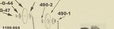
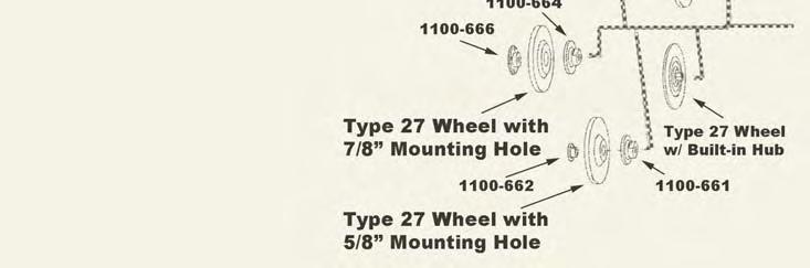
4 400-G-11 FRONT BEARING 400-G-25 MUFFLER 400-G-26 THROTTLE LEVER 400-G-34 SPRING 400-G-38 COLLET NUT 400-G-42 3/8 I.D. FLANGE ( G-47 3/8-24 JAM NUT KEY ROLL PIN 400-2G CYLINDER WITH PIN ROTOR BLADE (5 are REQ.) FRONT ENDPLATE RING SAFETY LEVER SAFETY LEVER PIN LOCKOUT LEVER SAFETY LEVER SPRING Aluminum Case S Steel Case MUFFLER Case 400-G-17 Exhaust (aluminum) 400-G- Exhaust (steel) 17-S ANGLE HEAD BEARING CAP UPPER OUTPUT BEARING KEY /8-24 X.980 OUTPUT CS COLLET OUTPUT /8-11 X.980 OUTPUT Wavy Washer (Note:2 are req d) LOWER OUTPUT BEARING SNAP RING REAR MOTOR BEARING GEAR SET SPACER RING REAR ENDPLATE MOTOR SPACER BEARING COVER SNAP RING DEAD HANDLE MOTOR CASE Offset Bracket 410-G-17 Alum Side Exhaust Sleeve 410-G- 17-S Steel Side Exhaust Sleeve 500-G-44 3/8 I.D. FLANGE ( G-47 1/2-13 JAM NUT A 1/2 I.D. FLANGE /8-11 JAM NUT THROTTLE LEVER PIN /8 I.D. FLANGE (6 OR SMALLER 3/8 I.D. FLANGE ( SCREW Star Washer for Bracket SCREW SET SCREW (SPECIFY SPEED) SNAP RING O-RING GASKET /8 NPT TO 3/8 NPT BUSHING /8 NPT TO 1/4 NPT BUSHING O-RING THROTTLE VALVE CAP THROTTLE VALVE-IN- CLUDES ASSEM- DESCRIPTION BLIES REPAIR KIT with Gear Set REPAIR KIT WITHOUT GEARS Safety Lever Assembly ACCESSORIES PART DESCRIPTION CP-53 WASHER /8 COLLET ADAPTER /32 1/4 TO 3/32 COLLET ADAPTER /8-24 TO 5/8-11 ADAPTER FOR 490-KR 490-K 3/8-24 X TYPE 27 ADAPTER KR 3/8-24 X TYPE 27 ADAPTER FOR 490-K NUT FOR 490-K & 490-KR /8-24 TO 5/8 I.D /8-24 TO 5/8 I.D /8-24 TO 5/8 I.D /8-24 TO 7/8 I.D /8-24 TO 7/8 I.D /8-24 TO 7/8 I.D /8 Adaptor for Type 1 wheels /8-11 TO 7/8 I.D /8-11 TO 7/8 I.D /8-11 TO 7/8 I.D /8-11 SANDING PAD NUT A 3/8-24 SANDING PAD NUT / SANDING PAD (MAX RPM) A 3/ SANDING PAD (MAX RPM) / SANDING PAD (MAX RPM) A 3/ SANDING PAD (MAX RPM) GUARDS PART DESCRIPTION TYPE 27 GUARD TYPE 27 GUARD TYPE 27 GUARD CLOSED FACE GUARD Master Parts Breakdowns Updated Feb. 1st 2006 Page 37
5 Part No. Description TOOLS PIN SPANNER WRENCH 102-SPWR WRENCH FOR SAND- ING PAD NUT /16 WRENCH /16 WRENCH /8 WRENCH /4 WRENCH /16 WRENCH INSTALLATION For most efficient operation, 90 psig (620 kpa) of clean dry air is required at the tool with the tool running, with-out extreme fluctuation. Minimum recommended hose size is 3/8 I.D. when the length of the hose is eight feet or less. An air line filter and lubricator, should be used. Hose should be blown out before attaching to the tool. Loss of Power A loss of power may not be related to the tool. First, check the air line pressure. It should be 90 psi at the tool while operating. LUBRICATION Lubricate the motor with an air line lubricator, using a light air motor oil. Adjust the lubricator to dispense one drop per cycle or three drops per minute. CAUTION Do not use substitutes for oil and grease. This could result in damage to the tool. MAINTENANCE 1. Proper and continuous lubrication. 2. Blow out air hose to assure a clean air supply. 3. Be sure the air filter and line lubricator are clean. 4. Fill the line lubricator before operation. 5. Place a few drops of oil into the air inlet of the tool be-fore attaching the air line. 6. Use moisture separators to remove water from the air line. 7. CAUTION Do not use solvent on bearings or on any parts made of a synthetic material. 8. Do not remove bearings unless replacement is necessary; bearings are a press fit. Page 38 Master Parts Breakdowns Updated Feb. 1st 2006
Output 0.9 H.P. (675 W) 9000 to R.P.M (11000rpm is standard)
 9000 to R.P.M (11000rpm is standard)") HENRY TOOLS Industrial Airtools at Work General Safety and Maintenance Manual COLLET SPINDLE SHOWN Model Number Exhaust Direction Throttle Type 44RAE Side (L) Lever or (K) Safety Lever Speed 9000 to 11000
HENRY TOOLS Industrial Airtools at Work General Safety and Maintenance Manual COLLET SPINDLE SHOWN Model Number Exhaust Direction Throttle Type 44RAE Side (L) Lever or (K) Safety Lever Speed 9000 to 11000
HENRY TOOLS. General Safety and Maintenance Manual MODELS 4402-RAS 4402-RASK 4402-RASC
 HENRY TOOLS Industrial Airtools at Work General Safety and Maintenance Manual K C Model Number 4402RAS 4402RAC Exhaust Direction Front or Side Throttle Type (L) Lever or (K) Safety Lever Speed 13500 R.P.M.
MODELS 48 RA 48 BRA2 48 BRA4 48 BRAD 48 RAS 48 RAZ 48 RAD 48 RAC
 General Safety and Maintenance Manual Model Number 48BRA 48BRAZ 48BRAC 48BRAD Exhaust Direction Front or Side Throttle Type (L) Lever or (K) Safety Lever Speed 9000 to 11000 R.P.M. (11000 is Standard)
MODELS 44 ARA 44 ARAC 44 RA4 44 RA2
 General Safety and Maintenance Manual Model 44ARA Angle Grinder with 4 guard. Model 44ARAC Angle Grinder with built in 1/4 collet for use with carbide burrs. Model 44ARAZ Angle Grinder with spiral cool
MODELS 45 RA 45 RAC 45 RAZ 45 RAS
 General Safety and Maintenance Manual Model Number 45RA 45RAZ 45RAS 45RAC SERIES PNEUMATIC RIGHT ANGLE GRINDER Exhaust Direction Side Throttle Type (L) Lever or (K) Safety Lever Speed 12000 to 14000 R.P.M
Throttle Type (L) Lever or (K) Safety Lever. Weight Length Diameter Air Aluminum Steel. 9.1 Inches (231 mm) 3.5 Lbs (1.6 Kg)
 Lever or (K) Safety Lever. Weight Length Diameter Air Aluminum Steel. 9.1 Inches (231 mm) 3.5 Lbs (1.6 Kg)") HENRY TOOLS Industrial Airtools at Wk General Safety and Maintenance Manual C C MODEL 46RAS shown with 4 Guard. MODEL 46RAC with 1/4 Collet f use with mounted points carbide burrs. Model Exhaust Number
HENRY TOOLS Industrial Airtools at Wk General Safety and Maintenance Manual C C MODEL 46RAS shown with 4 Guard. MODEL 46RAC with 1/4 Collet f use with mounted points carbide burrs. Model Exhaust Number
MODELS 46 ARA 46 ARAS 46 ARAC 46 RASD
 General Safety and Maintenance Manual MODEL 46RAS shown with 4 Guard. Model Number Exhaust Direction Front Side Throttle Type (L) Lever (K) Safety Lever Speed 13000 to 14000 R.P.M (13500rpm is standard)
General Safety and Maintenance Manual. Output. Type 0.9 H.P.675 W. (L) Lever or (K) Safety Lever R.P.M. (18000PM is standard)
 Lever or (K) Safety Lever R.P.M. (18000PM is standard)") HENRY TOOLS Industrial Airtools at Work General Safety and Maintenance Manual SUPER EXTENDED LENGTH DIE GRINDER FEATURING FRONT END DOUBLE ROW BEARINGS FOR SUPPORT. Multiple accessory mounting is possible
HENRY TOOLS Industrial Airtools at Work General Safety and Maintenance Manual SUPER EXTENDED LENGTH DIE GRINDER FEATURING FRONT END DOUBLE ROW BEARINGS FOR SUPPORT. Multiple accessory mounting is possible
General Safety and Maintenance Manual. Case Material. Output. Steel or Aluminum. 0.9 H.P. to 675 W R.P.M. (18000RPM
 H ENRY T OOLS Industrial Airtools at Wk General Safety and Maintenance Manual Model Number 41-G 41-G+3 41-G+6 Exhaust Direction Side (Side exhaust is Standard) Throttle Type (L) Lever (K) Safety Lever
Case Material. Output to R.P.M. Steel or Aluminum 0.9 H.P. 675 W
 HENRY TOOLS Industrial Airtools at Work General Safety and Maintenance Manual GOVERNED SPEED DIE GRINDER WITH ERICKSON COLLET FEATURING A SIDE EXHAUST Model Number Exhaust Direction Throttle Type 4721GL
MULTIPLE ACCESSORIES. Type R.P.M. (18000PM is standard) (L) Lever or (K) Safety Lever
 (L) Lever or (K) Safety Lever") HENRY TOOLS Industrial Airtools at Work General Safety and Maintenance Manual S SK MULTIPLE ACCESSORIES CAPACITY -2 Inch (50mm), 3 Inch (75mm) or 4 Inch (100mm) Type 1 wheels. NOTE: GUARD IS REQUIRED if
HENRY TOOLS Industrial Airtools at Work General Safety and Maintenance Manual S SK MULTIPLE ACCESSORIES CAPACITY -2 Inch (50mm), 3 Inch (75mm) or 4 Inch (100mm) Type 1 wheels. NOTE: GUARD IS REQUIRED if
General Operators Instructions and Maintenance Manual
 447RA Series Right Angle Grinders General Operators Instructions and Maintenance Manual 447RA(1)(2)(4) 447RA(C)(D) Read Safety Recommendations Before Operating Tool 447RA Series Right Angle Grinders Model
General Operators Instructions and Maintenance Manual
 45ARA Series Right Angle Grinders General Operators Instructions and Maintenance Manual 45ARA(1)(2)(4) 45ARA(C)(D) Read Safety Recommendations Before Operating Tool 45ARA Series Right Angle Grinders Model
Maintenance Information
 16573347 Edition 2 February 2014 Air Grinder Series 88H Maintenance Information Save These Instructions Product Safety Information WARNING Failure to observe the following warnings, and to avoid these
Maintenance Information
 16575128 Edition 2 May 2014 Air Grinder, Sander or Polisher 77A Series Maintenance Information Save These Instructions Product Safety Information Failure to observe the following warnings, and to avoid
Maintenance Information
 16573321 Edition 3 February 2014 Air Grinder Series 61H Maintenance Information Save These Instructions Product Safety Information WARNING Failure to observe the following warnings, and to avoid these
Maintenance Information
 16573370 Edition 2 February 2014 Air Grinder 99V Series Maintenance Information Save These Instructions Product Safety Information WARNING Failure to observe the following warnings, and to avoid these
Maintenance Information
 04581245 Edition 2 May 2014 Air Grinder, Die Grinder and Sander Series G2 (Angle) Maintenance Information Save These Instructions Product Safety Information WARNING Failure to observe the following warnings,
Maintenance Information
 Form 16573321 Edition 1 July 2004 Air Grinder Series 61H Maintenance Information Save These Instructions Always wear eye protection when operating or performing maintenance on this tool. Always turn off
Maintenance Information
 80234313 Edition 2 May 2014 Air Grinder, Die Grinder, Sander and Belt Sander Series G1 (Angle) Maintenance Information Save These Instructions Product Safety Information WARNING Failure to observe the
General Operators Instructions and Maintenance Manual
 487BRA Series Right Angle Grinders General Operators Instructions and Maintenance Manual 487BRA(1)(2)(4) 487BRA(C)(D) Read Safety Recommendations Before Operating Tool 487BRA Series Right Angle Grinders
Maintenance Information
 80234313 Edition 1 June 2006 Air Grinder, Die Grinder, Sander and Belt Sander Series G1 (Angle) Maintenance Information Save These Instructions WARNING Always wear eye protection when operating or performing
12 L * OH**
 Parts Manual Ersatzteil--Liste 12L27.. series 0.9 hp ERGO Short Coupled Low Profile Grinders & Sanders 45--8175 TOOL CLASSIFICATION 12 = ERGO Grinder/Sander 12 L 2 7 12 27 08* OH** -- TYPICAL MODEL THROTTLE
Maintenance Information
 16606022 Edition 3 May 2014 Air Drill 728 Series Maintenance Information Save These Instructions Product Safety Information WARNING Failure to observe the following warnings, and to avoid these potentially
Maintenance Information
 45761848 Edition 3 February 2014 Air Die Grinder AC4A, SC4A and XC4A Series Maintenance Information Save These Instructions Product Safety Information WARNING Failure to observe the following warnings,
Maintenance Information
 16575243 Edition 2 October 2013 Air Screwdrivers 1R Series Maintenance Information Save These Instructions Product Safety Information WARNING Failure to observe the following warnings, and to avoid these
Maintenance Information
 16572679 Edition 2 May 2014 Air Drill QP Series Maintenance Information Save These Instructions Product Safety Information WARNING Failure to observe the following warnings, and to avoid these potentially
General Operators Instructions and Maintenance Manual
 40AGH Series Horizontal Grinders General Operators Instructions and Maintenance Manual 40AGHL (COLLET) 40AGHLCW 40AGHL (TYPE 1) Read Safety Recommendations Before Operating Tool 40AGH Series Extended Grinders
General Operators Instructions and Maintenance Manual
 4123AG Series Die Grinders General Operators Instructions and Maintenance Manual 4123GL+6 4123GL Read Safety Recommendations Before Operating Tool 4123G Series Die Grinders Model Exhaust Throttle Number
General Operators Instructions and Maintenance Manual
 40AG Series Die Grinders General Operators Instructions and Maintenance Manual 40AGK+6 40AGK+3 40AGK Read Safety Recommendations Before Operating Tool Model Number Exhaust Direction Throttle Type Rated
General Operators Instructions and Maintenance Manual
 4111AG Series Die Grinders General Operators Instructions and Maintenance Manual 4111AGK (TYPE 1) 4111AGK+6 4111AGK+3 4111AGKCW 4111AGK (COLLET) Read Safety Recommendations Before Operating Tool Model
Maintenance Information
 16584062 Edition 3 December 2013 High Torque Reversible Angle Screwdrivers and Angle Wrenches QA1L High Torque Series Maintenance Information Save These Instructions Product Safety Information WARNING
OPERATION AND MAINTENANCE MANUAL for SERIES 7 AIR DRILLS
 03530896 OPERATION AND MAINTENANCE MANUAL for SERIES 7 AIR DRILLS Form P6532 Edition 10 February, 1994 TPD1388 IMPORTANT SAFETY INFORMATION ENCLOSED. READ THIS MANUAL BEFORE OPERATING TOOL. FAILURE TO
Maintenance Information
 16575219 Edition 4 October 2013 Air Screwdrivers QP1P, QP1S and QP1T Series Maintenance Information Save These Instructions Product Safety Information WARNING Failure to observe the following warnings,
Maintenance Information
 45528270 Edition 1 June 2007 Barring Motor T480 Series Maintenance Information Save These Instructions WARNING Always wear eye protection when operating or performing maintenance on this Barring Motor.
OPERATING INSTRUCTIONS AND SERVICE MANUAL
 OPERATING INSTRUCTIONS AND SERVICE MANUAL 55NAL--270-4 55NL--724-4 55RNL-2-LS-4- COMPLETE TOOL MODEL NO. CODE NO. 55NAL--270-4 20270 55NL--724-4 220724 READ SAFETY RECOMMENDATIONS 55RNL-2-LS-4-24089 BEFORE
General Safety and Maintenance Manual
 General Safety and Maintenance Manual MODEL 52H HORIZONTAL GRINDER WITH 6 GUARD MODEL 52HG HORIZONTAL GRINDER WITH 6 GUARD MODEL 52HSJ HORIZONTAL GRINDER WITH CONE WHEEL INSTALLED. 2 H.P. HORIZONTAL GRINDERS
3M Overhaul Service Kit
 SERVICE INSTRUCTIONS FOR 3M 12,000 RPM 5 in. (127 mm) and 6 in. (150 mm) RANDOM ORBITAL SANDERS 3M Overhaul Service Kit The part number 20347, 3M Overhaul Service Kit, contains all the replacement parts
3M Overhaul Service Kit
 SERVICE INSTRUCTIONS FOR 3M 12,000 RPM 3 in. (77 mm) RANDOM ORBITAL SANDERS 3M Overhaul Service Kit The part number 20346, 3M Overhaul Service Kit, contains all the replacement parts that naturally wear
General Operators Instructions and Maintenance Manual
 4002AGH Series Extended Grinders General Operators Instructions and Maintenance Manual 4002AGHL 4002AGHL+1 4002AGHK+6 Read Safety Recommendations Before Operating Tool 4002AGH Series Extended Grinders
General Operators Instructions and Maintenance Manual
 5201BH Series Horizontal Grinders General Operators Instructions and Maintenance Manual 5201BHLCW 5201BHL (TYPE 1) Read Safety Recommendations Before Operating Tool 5201BH Series Horizontal Grinders Model
Maintenance Information
 16572554 Edition 2 May 2014 Air Drill 44SMA, 44SMA-EU Maintenance Information Save These Instructions Product Safety Information WARNING Failure to observe the following warnings, and to avoid these potentially
Maintenance Information
 16596199 Edition 2 May 2014 Air Drill 33 Series Maintenance Information Save These Instructions Product Safety Information WARNING Failure to observe the following warnings, and to avoid these potentially
1988 Chevrolet Pickup V SUSPENSION - FRONT (4WD)' 'Front Suspension - "V" Series 1988 SUSPENSION - FRONT (4WD) Front Suspension - "V" Series
' 'Front Suspension - V Series 1988 SUSPENSION - FRONT (4WD) Front Suspension - V Series") 1988 SUSPENSION - FRONT (4WD) Front Suspension - "V" Series DESCRIPTION NOTE: Vehicle serial numbers used in this article has been abbreviated for common reference to Chevrolet and GMC models. Chevrolet
1988 SUSPENSION - FRONT (4WD) Front Suspension - "V" Series DESCRIPTION NOTE: Vehicle serial numbers used in this article has been abbreviated for common reference to Chevrolet and GMC models. Chevrolet
Maintenance Information
 16605958 Edition 2 May 2014 Air Percussive Rivet Buster Models 9001 and 11001 Maintenance Information Save These Instructions Product Safety Information WARNING Failure to observe the following warnings,
General Operators Instructions and Maintenance Manual
 57AH Series Horizontal Grinders General Operators Instructions and Maintenance Manual 57AHL (COLLET) 57AHLCW 57AHL (TYPE 1) Read Safety Recommendations Before Operating Tool 57AH Series Extended Grinders
General Safety and Maintenance Manual. Bore and Stroke. Throttle Type. Blows per Minute. (L) Lever Inches (564 mm)
 Lever Inches (564 mm)") HENRY TOOLS Industrial Airtools at Work General Safety and Maintenance Manual Bench Rammer and Floor Rammers Model Number Bore and Stroke 1.0 Inch x 4.0 Inch (25 mm x 102 mm) Throttle Type Blows per Minute
HENRY TOOLS Industrial Airtools at Work General Safety and Maintenance Manual Bench Rammer and Floor Rammers Model Number Bore and Stroke 1.0 Inch x 4.0 Inch (25 mm x 102 mm) Throttle Type Blows per Minute
0.4 hp. Right Angle Tools
 0.4 hp. Right Angle Tools Models: 50210, 50211, 50561, 50570 Lubricants: 95842 Dynabrade Air Lube 10W/NR 95848 Gear Oil Lubricant Gun: 95541 Push-Type Gun 0.4 hp. Right Angle Tools Models: 50210, 50211,
Disassembly Instructions hp. Dynafile II Models: 40352, 40353
 Disassembly Instructions - 0.4 hp. Dynafile II Models: 40352, 40353 Important: Use these instructions along with the tool parts page or manual. Notice: Shut off the air supply and depress throttle lever
Maintenance Information
 48393383 Edition 01 April 2012 Air Starters for Internal Combustion Engines SS100 Series Maintenance Information Save These Instructions General Instructions 1. Reference Parts Information Manual for item
Transmission Overhaul Procedures-Bench Service
 How to Assemble the Lower Reverse Idler Gear Assembly Special Instructions In 1996 Eaton changed the reverse idler system design. In the nut design, the reverse idler bearing was lubricated through a hole
Disassembly Instructions hp. Mini-Dynafile II
 Disassembly Instructions - 0.4 hp. Mini-Dynafile II Important: Use these instructions along with the tool parts page or manual. Notice: Shut off the air supply and depress throttle lever to deplete the
Maintenance Instructions
 General Note These instructions contain information common to more than one model of Bevel Gear Drive. To simplify reading, similar models have been grouped as follows: GROUP 1 Models 11, 0, 1,, (illustrated),,
REPAIR MANUAL URW SERIES. URW-6, 8, 9, 10 & 12 Series Repair Manual
 REPAIR MANUAL URW SERIES URW-6, 8, 9, 10 & 12 Series Repair Manual Contents Page 1. Tools Needed for Repair 1 2. Disassembly and Reassembly of the Cam Casing 2-4 3. Disassembly and Reassembly of the Gear
Disassembly Instructions hp. Dynafile II Models: 40320, 40321, 40324, 40326, 40330, 40335
 Disassembly Instructions - 0.5 hp. Dynafile II Models: 40320, 40321, 40324, 40326, 40330, 40335 Important: Use these instructions along with the tool parts page or manual. Notice: Shut off the air supply
INSTRUCTIONS FOR OVERHAUL OF RAMEY RE SERIES WINCH
 INSTRUCTIONS FOR OVERHAUL OF RAMEY RE 12000 SERIES WINCH DISASSEMBLY 1. Drain oil from gear housing by removing plug # from bottom of gear housing. Remove relief fitting # and reducer # from top of gear
PARTS LIST FOR NO. 1 SERIES 1AM ANGLE TOOLS 17 (SERIAL B )
") Form ZA Date 0December/G Page of NON-REVERSING Housing And Motor 0 REVERSING 0 0. Housing Sleeve (Long)(00, 00, 00 RPM) Housing Sleeve (Short)(00, 00, 00, 00 RPM). Pin. Ball Bearing. Lower End Plate. O-Ring.
Form ZA Date 0December/G Page of NON-REVERSING Housing And Motor 0 REVERSING 0 0. Housing Sleeve (Long)(00, 00, 00 RPM) Housing Sleeve (Short)(00, 00, 00, 00 RPM). Pin. Ball Bearing. Lower End Plate. O-Ring.
Drive/Motor Disassembly: Assembly Instructions - Quick-Change Pencil Grinder. Header 1. xxxxxx
 Disassembly/Assembly Instructions - Quick-Change Pencil Grinder, Drive & Motor Models: 60051, 60052 Important: Use these instructions along with tool parts page or manual. Notice: Shut off air supply.
3,200 RPM Angle-Head WARNING
 Model: 50046 Angle-Head Kit 54002 Mini-Dynorbital Sander 54003 Mini-Dynorbital Sander 50223 2" Disc Sander 51091 Die Grinder 53026 Drill 50047 3" Buffer 50070 Finesse Sanding Kit Parts Page Reorder No.
Parts Information. Air Grinders, Air Die Grinders, Air Sanders and Air Belt Sanders. Save These Instructions. G1 Series (Angle)
") 80156458 Edition 5 May 2014 Air Grinders, Air Die Grinders, Air Sanders and Air Belt Sanders G1 Series (Angle) Parts Information Save These Instructions G1 Series (Angle) Air Grinder, Die Grinder, Sander
80156458 Edition 5 May 2014 Air Grinders, Air Die Grinders, Air Sanders and Air Belt Sanders G1 Series (Angle) Parts Information Save These Instructions G1 Series (Angle) Air Grinder, Die Grinder, Sander
Sachs shock manual. ( ) 2 & 4 Stroke RR Enduro. ( ) RS Dual Sport
 2 & 4 Stroke RR Enduro. ( ) RS Dual Sport") Sachs shock manual (2013 2015) 2 & 4 Stroke RR Enduro (2014-2015) RS Dual Sport 1 Introduction The procedures in this manual must take place in a clean environment using professional tools and some specific,
Sachs shock manual (2013 2015) 2 & 4 Stroke RR Enduro (2014-2015) RS Dual Sport 1 Introduction The procedures in this manual must take place in a clean environment using professional tools and some specific,
Fig Variable Speed Valve Parts
 5 DISASSEMBLY OF VARIABLE SPEED CONTROL VALVE (Seal Replacement with Control Valve in the Bobcat). Remove seat and seat plate (Fig. ).. Remove variable speed control lever linkage rod. 3. Remove temperature
Service Tools. Service and Repair Manual Model 900/950/990 ITEM PART NO. DESCRIPTION ITEM PART NO. DESCRIPTION ITEM PART NO.
 12 1 3 2 4 5 8 10 6 7 9 11 14 24 12 13 17 22 29 18 23 25 19 26 15 20 27 21 16 22 33 37 38 32 31 36 30 34 35 40 41 42 43 ITEM PART NO. DESCRIPTION 1 9170 0231 30 LONG ALLEN KEY 2 9170 0737 20 3/32 PIN PUNCH
CLUTCH CONTENTS SERVICE DIAGNOSIS. (a) Worn or damaged disc assembly. (b) Grease or oil on disc facings. (c) Improperly adjusted cover assembly.
 Worn or damaged disc assembly. (b) Grease or oil on disc facings. (c) Improperly adjusted cover assembly.") CLUTCH CONTENTS -GROUP 6 Page CLUTCH HOUSING ALIGNMENT... 6 CLUTCH PEDAL FREE PLAY 1 CLUTCH RELEASE BEARING 5 CLUTCH RELEASE FORK... 5 CLUTCH SERVICING 2 PILOT BUSHING CRANKSHAFT TO TRANSMISSION DRIVE
CLUTCH CONTENTS -GROUP 6 Page CLUTCH HOUSING ALIGNMENT... 6 CLUTCH PEDAL FREE PLAY 1 CLUTCH RELEASE BEARING 5 CLUTCH RELEASE FORK... 5 CLUTCH SERVICING 2 PILOT BUSHING CRANKSHAFT TO TRANSMISSION DRIVE
INGERSOLL -RAND. A WARNING AIR MOTORS OPERATION AND MAINTENANCE MANUAL
 03523545 Form P5815 Edition 13 June, 1998 OPERATION AND MAINTENANCE MANUAL FOR MODELS 4800D, 4800K, 4800M, 4800N, 4800P, 4800Q, 4800S AND 4800U NONREVERSIBLE AND MODELS 4840D, 4840K, 4840M, 4840N, 4840P,
REPAIR PROCEDURES MANUAL
 REPAIR PROCEDURES MANUAL PVX Series Vane Pumps A Design Series Step-by-Step Guide to Troubleshooting and Repairing PVX Series Vane Pumps Introduction Thank you for choosing Continental Hydraulics PVX Vane
STERNDRIVE UNIT 3 B GEAR HOUSINGS MR/ALPHA ONE/ALPHA ONE SS
 STERNDRIVE UNIT 3 B 23146 GEAR HOUSINGS MR/ALPHA ONE/ALPHA ONE SS Table of Contents Page Identification........................... 3B-1 Specifications.......................... 3B-1 Torque Specifications................
CP3650 Series CP AB & CP AB Angle Sanders
 32 CP3650-20AB CP3650-075AB rpm CP3650-20AB 2000 CP3650-075AB 7500 Index No. Parts No. Description Qty Index No. Parts No. Description Qty 653967390 Adaptater 6 654300330 Inlet 7 656452290 Disc Spring
Amarillo PUMP DRIVES (250 HP THROUGH 350 HP) INSTRUCTIONS FOR REPAIRING MODELS 250, 300, and 350
 INSTRUCTIONS FOR REPAIRING MODELS 250, 300, and 350") Amarillo PUMP DRIVES (250 HP THROUGH 350 HP) INSTRUCTIONS FOR REPAIRING MODELS 250, 300, and 350 Amarillo Right Angle Pump Drives, if properly installed and maintained, should provide years of service
Amarillo PUMP DRIVES (250 HP THROUGH 350 HP) INSTRUCTIONS FOR REPAIRING MODELS 250, 300, and 350 Amarillo Right Angle Pump Drives, if properly installed and maintained, should provide years of service
1989 Jeep Cherokee. STEERING COLUMN' '1989 STEERING Jeep Steering Columns STEERING COLUMN STEERING Jeep Steering Columns
 STEERING COLUMN 1989 STEERING Jeep Steering Columns DESCRIPTION All models use collapsible steering columns. All columns have integral ignition switch and locking device. Optional tilt wheel is available
Maintenance Information
 Form 16575334 Edition 1 April 2005 Electric Screwdrivers EL, EP and ET 34V DC Series Maintenance Information Save These Instructions WARNING Maintenance procedures have the potential for severe shock hazard
Disassembly Instructions hp Dynafile
 Disassembly Instructions - 0.5 hp. 14000 Dynafile Important: Use these instructions along with the tool parts page or manual. Notice: Shut off the air supply and depress throttle lever to dissipate the
PROPELLER SHAFT & DIFFERENTIAL CARRIER SECTIONPD CONTENTS
 PROPELLER SHAFT & DIFFERENTIAL CARRIER SECTIONPD CONTENTS PREPARATION...2 PROPELLER SHAFT...5 On-Vehicle Service...6 Removal and Installation...7 Inspection...7 Disassembly...7 Assembly...8 ON-VEHICLE
Models: Standard Machine, NWN Machine Screw Guide Screw Screw Button Screw Support Rod
 Effective Serial Number Reference Table Model Number Serial Number 40320, 40321 36300 40326 1284 40330 3001 40335 1129 Models: 40320 Standard Machine 40326 20-1/2" Long Belt Machine 40330 Vacuum Machine
4.2 WATER PUMP (GEAR CASE MOUNTED AND LATER) (GCM)
 (GCM)") SERIES 60 SERVICE MANUAL 4.2 WATER PUMP (GEAR CASE MOUNTED - 1991 AND LATER) (GCM) The centrifugal-type water pump circulates the engine coolant through the cooling system. The pump is mounted on the rear
SERIES 60 SERVICE MANUAL 4.2 WATER PUMP (GEAR CASE MOUNTED - 1991 AND LATER) (GCM) The centrifugal-type water pump circulates the engine coolant through the cooling system. The pump is mounted on the rear
REFILL STATION REBUILD KIT P/N 14270NOS
 REFILL STATION REBUILD KIT P/N 14270NOS INSTRUCTION SHEET P/N 199R10338 1.0 DISASSEMBLY This procedure describes the removal of the air module from the fluid module and complete disassembly of the pump.
Installation Instructions
 Preparing your vehicle to install your brake system upgrade 1. Rack the vehicle. 2. If you don t have a rack, then you must take extra safety precautions. 3. Choose a firmly packed and level ground to
Maintenance Information
 Form 04584058 Edition 1 November 2004 Air Impactool 2141P and 2141PSP Maintenance Information Save These Instructions Disassembly General Instructions 1. Do not disassemble the tool any further than necessary
SIOUX TOOLS FORCE PRODUCT CATALOG ABRASIVE
 SIOUX TOOLS FORCE PRODUCT CATALOG ABRASIVE Abrasive Index Straight Die Grinders......................... 25 Right Angle Die Grinders...................... 26 23 SIOUX TOOLS FORCE PRODUCT CATALOG Make Easy
Backwater Performance Systems Large Vanguard Mikuni Twin Carburetor Kit
 Backwater Performance Systems Large Vanguard Mikuni Twin Carburetor Kit 1. Throttle Cable Twin (CKC-41) 2. Carburetor VM30mm (CKC-40) 3. Loctite 242.5mL (A-210) 4. Air Cleaner Filter 6000 (EC-86) 5. Rev
TCI Trans-Scat
 Page 1 of 5 Return to Instruction Sheet index TCI 400000 Trans-Scat Turbo Hydramatic 400-1965-Up This kit will allow you to re-program your transmission valve body. This kit will give you firm positive
DISASSEMBLY AND ASSEMBLY
 205-03-1 Front Drive Axle/Differential Ford 8.8-Inch Ring Gear 205-03-1 DISASSEMBLY AND ASSEMBLY Axle Front Drive Special Tool(s) 2-Jaw Puller 205-D072 (D97L-4221-A) Special Tool(s) Carrier Bearing Replacer
Precision Grinders 50, ,000 RPM
 Precision Grinders 50,000 100,000 RPM 0.06 0.2 hp (0.044 0.015 kw) Variety of configurations to meet all your application needs Ideal for precision deburring and metal removal Turbine, governed and nongoverned
UOW Series Repair Manual UOW-11 & UOW-T60 Series
 UOW Series Repair Manual UOW-11 & UOW-T60 Series 100000 SE Pine St., Portland, OR 97216 800-852-1368 503-254-6600 www.aimco-global.com Contents Page 1. Tools Needed for Repair 2 2. Disassembly and Reassembly
REMOVAL & INSTALLATION
 REMOVAL & INSTALLATION CENTER BEARING SUPPORT ASSEMBLY Removal 1. With transmission in neutral and parking brake off, raise vehicle. Scribe alignment marks on all flange/yokes and slip joints to be disassembled
Hard Seat Fluid Pressure Regulator
 Instruction Sheet P/N 04742-02 Description The Nordson hard seat fluid pressure regulator is designed for use with abrasive coatings. The regulator body is constructed of stainless steel with a nickel-plated
20-G SERIES PRECISION DIE GRINDERS (.2 hp) 40-G & 41-G SERIES DIE GRINDERS (.9 hp) 4110 & 4111 SERIES DIE GRINDERS (.9 hp)
 40-G & 41-G SERIES DIE GRINDERS (.9 hp) 4110 & 4111 SERIES DIE GRINDERS (.9 hp)") 20-G SERIES PRECISION DIE GRINDERS (.2 hp) DIE GRINDER KIT (Add a "K" to end of tool model number). Includes: (1) 20-G or 20-GM (1) 3 /,6" dia. x 5' long hose (4) '/a" carbide burrs - Cylindrical plain
20-G SERIES PRECISION DIE GRINDERS (.2 hp) DIE GRINDER KIT (Add a "K" to end of tool model number). Includes: (1) 20-G or 20-GM (1) 3 /,6" dia. x 5' long hose (4) '/a" carbide burrs - Cylindrical plain
REAR DRIVE SHAFT (3S GTE ENGINE)
") SA52 REAR DRIVE SHAFT (3SGTE ENGINE) COMPONENTS SA53 NOTICE: The axle bearing could be damaged if it is subjected to the vehicle weight, such as when moving the vehicle with the drive shaft removed. Therefore,
SA52 REAR DRIVE SHAFT (3SGTE ENGINE) COMPONENTS SA53 NOTICE: The axle bearing could be damaged if it is subjected to the vehicle weight, such as when moving the vehicle with the drive shaft removed. Therefore,
I & M Mark 78 Series. Ideal Installation. Start-Up. Installation & Maintenance Instructions for Mark 78 Control Valves (1-1/2-2 )
") I & M Mark 8 Series 0 Wasson Road Cincinnati, OH 4509 USA Phone 5-5-5600 Fax 5-8-005 info@richardsind.com www.jordanvalve.com Installation & Maintenance Instructions for Mark 8 Control Valves (-/ - ) Warning:
I & M Mark 8 Series 0 Wasson Road Cincinnati, OH 4509 USA Phone 5-5-5600 Fax 5-8-005 info@richardsind.com www.jordanvalve.com Installation & Maintenance Instructions for Mark 8 Control Valves (-/ - ) Warning:
COLT 2310, 2510, AND 2712 COM PACT TRACTORS CHAPTER 7 BEARINGS, SEALS, GASKETS
 COLT 2310, 2510, AND 2712 COM PACT TRACTORS CHAPTER 7 BEARINGS, SEALS, GASKETS END PLAY SEE SPECIFICATIONS "A" SHIM C" GASKET "B" STEEL WASHER IF REQUIRED 7-A-l Figure 7-A-l illustrates the correct assembly
STRAIGHT DIE GRINDER MODEL EGA530 OWNERS MANUAL
 STRAIGHT DIE GRINDER MODEL EGA530 OWNERS MANUAL www.eaglecompressor.com 1-800-551-2406 READ THE ENTIRE MANUAL BEFORE PUTTING THIS TOOL IN SERVICE Limited Air Tool Warranty Eagle warrants air tools of its
2. Disconnect negative battery cable to avoid possible fuel discharge if an accidental attempt is made to start the engines.
 PART #25001 LT1 Adjustable Fuel Pressure Regulator, 1994-1997 PACKING LIST Before installation, use this check list to make sure all necessary parts have been included. ITEM QTY CHECK PART NUMBER DESCRIPTION
3.2 DRIVE TORQUE HUB. Roll, Leak and Brake Testing SECTION 3 - CHASSIS & TURNTABLE. 3-2 JLG Lift
 3.2 DRIVE TORQUE HUB Roll, Leak and Brake Testing 10 LUG PATTERN Torque-Hub units should always be roll and leak tested before disassembly and after assembly to make sure that the unit's gears, bearings
I & M Mark 78 Series. Ideal Installation. Start-Up. Installation & Maintenance Instructions for Mark 78 Control Valves (1/2-1 )
") I & M Mark 8 Series 30 Wasson Road Cincinnati, OH 4509 USA Phone 53-533-5600 Fax 53-8-005 info@richardsind.com www.jordanvalve.com Installation & Maintenance Instructions for Mark 8 Control Valves (/ -
I & M Mark 8 Series 30 Wasson Road Cincinnati, OH 4509 USA Phone 53-533-5600 Fax 53-8-005 info@richardsind.com www.jordanvalve.com Installation & Maintenance Instructions for Mark 8 Control Valves (/ -
DRIVE AXLE Volvo 960 DESCRIPTION & OPERATION AXLE IDENTIFICATION DRIVE AXLES Volvo Differentials & Axle Shafts
 DRIVE AXLE 1994 Volvo 960 1994 DRIVE AXLES Volvo Differentials & Axle Shafts 960 DESCRIPTION & OPERATION All 960 station wagon models use type 1041 rear axle assembly. All 960 4-door models use type 1045
Service Guide. High-Pressure Grease Pump. 100 psi (6.8 bar) High-Pressure Pump Model 7785 Series Specifications
 High-Pressure Pump Model 7785 Series Specifications") Description Service Guide 7785-A5 7785-B5 7785-MA The major components of the pump models in the 7785 series consist of an air-operated motor and a pump tube. The air motor connects directly to the double-acting
Description Service Guide 7785-A5 7785-B5 7785-MA The major components of the pump models in the 7785 series consist of an air-operated motor and a pump tube. The air motor connects directly to the double-acting
Rocker Lever Assembly
 003-009 Rocker Lever Assembly Preparatory Steps Remove the air piping from the intake manifold. Remove the rocker lever cover. Refer to Procedure 003-011 in Section 3. Remove the engine brakes, if equipped.
CP3850 Series Grinders
 1/11 1 Spring cylindrical 6156811670 1 1 1 1 1 X 2 Warning label 6158713860 1 1 1 1 1 X 3 CP plate 2050553403 1 1 1 1 1 X 4 Name plate 2050553413 1 1 1 1 1 X 5 Ring screw 6156731760 1 1 1 1 1 X 6 Autobalancer
TECHNICAL INFORMATION
 TECHNICAL INFORMATION Model No. Description GA5020C/GA6020C, GA5021C/GA6021C Angle Grinders 125mm (5") /150mm (6") L PRODUCT P 1/10 CONCEPT AND MAIN APPLICATIONS These four models have been developed as
POWER STEERING PUMP REBUILDING SPK101 Read instructions completely before removal & disassembly
 POWER STEERING PUMP REBUILDING SPK101 Read instructions completely before removal & disassembly DISASSEMBLY: 1. Remove pump from car and allow to drain. 2. Remove pulley from front of pump. This requires