FLOW METER TROUBLESHOOTING
|
|
|
- Leonard Blake
- 6 years ago
- Views:
Transcription
1 FLOW METER TROUBLESHOOTING FLOW METER TROUBLESHOOTING


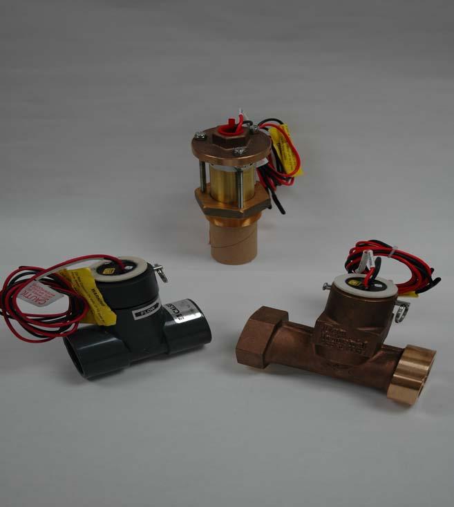
2 FLOW METER TROUBLESHOOTING FLOW METER PARTS IDENTIFICATION FLOW METER PARTS RETAINING PIN RING RETAINING PIN FLOW METER ASSEMBLY FIELD WIRING FLOW METER INSERT IMPELLER PIN IMPELLER FLOW METER HOUSING FMIX FLOW METER INSERT ALLEN WRENCH ANTI-SEIZE LUBRICATION ALIGNMENT TOOL INSTALLATION DEPTH GAUGE FMBX FLOW METER INSERT FMIX / FMBX TOOLS FMIX / FMBX INSERTS

3 FLOW METER TROUBLESHOOTING FLOW METER TROUBLESHOOTING The Calsense Flow Meter enables all Calsense Irrigation Controllers to measure the flow rate of an irrigation system, it an important management tool in detecting mainline breaks, broken risers, and closed or stuck valves and tracking water usage for management reports. It is installed in the main line, after the water meter or backflow preventer. REQUIRED TOOLS Digital Multi-meter. Common Screwdriver Philips Screwdriver Wire Strippers 2 Dri-Splice Connectors (Hardening Type) 2 Yellow Wire Nuts Calsense FMI Insert AWG wire PROBLEM: NO FLOW EXAMPLE: NORMAL FLOW 9.0 GPM MEASURED 0.0 GPM Description: This is an alert that appears on the display screen of the 2100, ET1, and ET2000 controllers when a NO FLOW condition occurs in the system. If a NO FLOW alert is detected on all stations or a group of stations on the controller, there could be a problem in a number of places in the irrigation system. The following areas that these problems could arise from are the water meter, back flow, master valve isolation valve, field wiring, flow meter or the controller. The following procedures will help in determining where a problem has occurred.


4 FLOW METER TROUBLESHOOTING TEST Using the TEST key, test a station that you can see from the controller for two (2) minutes. Verify that the station you have turned on is running and has stabilized. If after verifying that the system is working properly and no flow readings appear on the display screen, proceed to SECTION 2. If after testing and verifying that there is no water running from the system and no flow readings from the controller display, follow the steps in SECTION 1 before proceeding to SECTION 2. SECTION 1 STEP 1 Do not remove the controller or the flow insert. Check the following first. Water meter: Check that the Water Meter is not locked for non-payment, or turned OFF for repairs in the system. SECTION 1 STEP 2 Back flow Preventer: Check that the curb stop and ball / gate valves on the back flow device are in the OPEN position.


5 FLOW METER TROUBLESHOOTING Master Valve: SECTION 1 STEP 3 Check the Master Valve setup in the controller for correct entry: Normally Open, Normally closed. Also check for the flow control turned down, wires not connected, or bad solenoid. Isolation Valves: SECTION 1 STEP 4 Inspect the Mainline and RCV manifolds. Check that these valves have not been turned down. Isolation Valves: SECTION 1 STEP 5 Check for isolation valves to make sure that they have not been turned OFF.


6 FLOW METER TROUBLESHOOTING SECTION 1 STEP 6 RCV (Remote Control Valves): Check for any RCV Valves that might have been recently worked on. It is possible that the flow control on the RCV Valve has been turned down. NOTE After checking Section 1 items 1 through 4 and finding everything okay. Proceed to Section 2. SECTION 2 STEP 1 Disconnect the RED and BLACK wires in the black harness from the field wires going to the Flow Meter. If using a terminal block or TP-1 Board, disconnect the field wires from the terminal block or TP-1 Board.


7 FLOW METER TROUBLESHOOTING SECTION 2 STEP 2 With a Digital Multi-Meter measure the DC voltage on the terminal strip. You should read 9.5 to 12.0 volts DC. SECTION 2 STEP 3 Tap the RED and BLACK wires together to see if you get flow readings on the controller display. SECTION 2 STEP 4 You should see a flow reading in the lower left corner of the controller display move from 0.0 GPM to a higher number.


8 FLOW METER TROUBLESHOOTING NOTE (The steps in Section 2 verify that the controller Is good). If Section 2 Steps 1 through 6 check out okay, reconnect your wires and proceed to TESTING AT THE FLOW METER. TESTING AT THE FLOW METER STEP 1 At the Flow Meter location, cut out the wire connections. Strip the Flow meter and field wire ends. Check for discolored or corroded wire connections. This would be an indication of an improper connection. TESTING AT THE FLOW METER STEP 2 With the field wires connected at the TP- 1 Board, check the DC voltage on the field wires to the controller. You should read between 9.5 to 11.0 volts DC. This would be an indication of good field wires. If you do not read voltage the field wiring is faulty.


9 FLOW METER TROUBLESHOOTING TESTING AT THE FLOW METER STEP 3 In the case where a digital Multi-meter is not available, have someone located at the controller to view the controller screen. Begin tapping together the two field wires going to the controller. You should see a flow reading in the lower left corner of the controller display move from 0.0 GPM to a higher number. No flow indicates bad wiring. TESTING AT THE FLOW METER STEP 4 Reconnect the field wires to the Flow Meter using two (2) yellow wire nuts. At the controller test the same station as before to see if the controller reads flow. REMOVING THE FLOW METER INSERT CAUTION: This next step requires the removal of the Flow Meter insert. Extreme care must be taken when removing the Flow Meter insert. Turn OFF the water supply to the irrigation system. (This should include all Water Meters, Isolation Valves, Hose bibs, etc. to relieve the pressure off of the mainline).

10 FLOW METER TROUBLESHOOTING REMOVING THE FLOW METER INSERT STEP 1 CAUTION: Do not position your head or body directly over the Flow Meter. Remove the ring from the stainless steel pin that holds the insert in the flow body. NOTE Note the direction of the arrow on the top of the insert in the flow body. Note the direction of the arrow on top of the insert. It is important that when reinstalling the insert into the body of the Flow Meter that the arrow be in the same direction as the flow. REMOVING THE FLOW METER INSERT STEP 2 With the palm of your hand firmly on top of the insert, push the ring end of the stainless steel pin toward the body of the Flow Meter insert with your other hand.


11 FLOW METER TROUBLESHOOTING REMOVING THE FLOW METER INSERT STEP 3 With the palm of your hand still firmly on top of the insert. Completely remove the stainless steel pin from the body of the flow meter insert. REMOVING THE FLOW METER INSERT STEP 4 With the palm of your hand still firmly on top of the insert. Gently pry up the lip of the Flow Meter insert with a common screwdriver moving the insert about a ¼ inch past the first O-Ring. REMOVING THE FLOW METER INSERT STEP 5 With your hand that you are using to hold down the top of the flow meter insert, firmly grab the Flow Meter insert. Slowly lift the Flow Meter insert out of the body of the Flow Meter being careful not to allow any debris to enter the body of the Flow Meter. Check the paddle wheel for any damage. Check the inside of the Flow Meter body for any debris.
12 FLOW METER TROUBLESHOOTING TESTING THE FLOW METER INSERT STEP 1 Take the removed Flow meter insert to the controller. Connect the Flow Meter insert to the Flow RED and Flow BLACK terminals. TESTING THE FLOW METER INSERT STEP 2 Spin the paddle wheel. You should observe a flow reading in the lower left hand corner of the display move from 0.0 GPM to a higher number. When the paddle wheel stops the number should return to 0.0 GPM. If no number appears or the numbers jump around without spinning the paddle wheel the Flow Meter insert is bad. TESTING THE FLOW METER INSERT STEP 3 At the controller, connect the new Flow Meter insert to the Flow RED and Flow BLACK terminals. Spin the paddle wheel. You should observe a flow reading in the lower left hand corner of the controllers display move from 0.0 GPM to a higher number. When the paddle wheel stops the number should return to 0.0 GPM.

13 FLOW METER TROUBLESHOOTING INSTALLING THE FLOW METER INSERT STEP 1 Insert the new Flow Meter insert into the body of the Flow Meter, sure that the arrow on the top of the Flow Meter insert is pointing in the same direction as the direction of flow. INSTALLING THE FLOW METER INSERT STEP 2 Re-insert the stainless steel pin and reconnect the ring to the end of the stainless steel pin. INSTALLING THE FLOW METER INSERT STEP 3 Reconnect the field wires with recommended water proof connections. This concludes Flow MeterTroubleshooting
14 FLOW METER TROUBLESHOOTING NOTE If after checking steps 1 through 3 Installing the Flow Meter everything does not check okay. Follow the procedure for: Wire verification test ISOLATION OHM TEST Tests for nicks, bad splices and loose strands on terminal blocks. Description: In this test you will be OHM measurements between the wires you are testing. The wires are not to be connected at either end to anything. They should not be touching the ground. When OHM measurements between pieces of wire, you should see no difference in the meter reading than if meter leads aren t touching anything. The meter should read infinite or OL as the Fluke meters show (OL stands for overload). ISOLATION OHM TEST STEP 1 Isolate all wires involved. This means disconnect at both ends.


15 FLOW METER TROUBLESHOOTING ISOLATION OHM TEST STEP 2 Make OHM measurement between the various pieces of wire and each other. Test all combinations. You should see a reading of OL. (OL stands for overload). ISOLATION OHM TEST STEP 3 Make OHM measurements between the various pieces of wire and the ground rod. If no ground rod is available, jab your meter probe straight into the ground. You should read OL on the meter. ISOLATION OHM TEST STEP 4 Make OHM measurements between the various pieces of wire and the field common. You should read OL on the meter.

16 FLOW METER TROUBLESHOOTING LOOP OHM TEST Tests for bad splices, bad connections, broken wires and crossed pairs. Description: In this test you will be OHM measurements between the wires with them twisted together at the other end of the cable. The wires are not to be connected to anything. They should not be touching the ground. When OHM measurements between the pieces of wire you should have readings similar to the reading you get when you touch your two-meter leads together. As the wire lengths increase, you will start to see OHM numbers. Numbers like 1 or 2 OHMs may be common. You should not expect to see 20 OHMs however. LOOP OHM TEST STEP 1 Isolate all wires involved. This means disconnect at both ends. (Recommend you perform the ISOLATION OHM TEST at this point, if you have not done it already). LOOP OHM TEST STEP 2 At one end of the cable, take two wires and twist them together. If there are more than two wires, you may repeat ending up with more than one twist. Each twist involves only two wires.

.")
17 FLOW METER TROUBLESHOOTING LOOP OHM TEST STEP 3 Make OHM measurements between the pieces of wire that are twisted together. You should see low readings. LOOP OHM TEST STEP 4 Repeat the tests changing the groups of wires. For example, if your first pairs were RED / BLUE and BLACK / ORANGE repeat the test using RED / ORANGE and BLUE / BLACK pairs. (You repeat the test to find crossed pairs. No matter how many wires involved, you only need to change your pairs once). NOTE THIS WILL CONCLUDE THE WIRE VERIFICATION TESTS
18 FLOW METER TROUBLESHOOTING 2075 Corte del Nogal, Suite P, Carlsbad CA (800) FAX: 1-(760) Stock Number: PG1-FM-E1 Rev. 03/06
WeatherTRAK FlowLink Installation Instructions 04/23/2013 Revision 2 HydroPoint Customer Support
 WeatherTRAK FlowLink Installation Instructions 04/23/2013 Revision 2 HydroPoint Customer Support support@hydropoint.com (800) 362-8774 WeatherTRAK FlowLink Installation Instructions Rev 2 1 Introduction
KEYLESS ENTRY SYSTEM
 KEYLESS ENTRY SYSTEM 1995 Volvo 850 1995 ACCESSORIES & EQUIPMENT Volvo Keyless Entry Systems 850 DESCRIPTION & OPERATION 850 models with central locking and factory installed alarm system can be equipped
Model 800 Disassembly Instructions and Troubleshooting
 Model 800 Disassembly Instructions and Troubleshooting 1 Index Page Solenoid Disassembly Instructions 2,3 Removing Adaptor from Anti-siphon Body 4,5 Adaptor Disassembly Instructions 6-9 Troubleshooting
COMPONENT WORK SAMPLE 15 Electrical Circuitry & Print Reading MAINTENANCE MANUAL
 COMPONENT WORK SAMPLE 15 Electrical Circuitry & Print Reading MAINTENANCE MANUAL TABLE OF CONTENTS SECTION TITLE PAGE 1A CHECKING THE BATTERIES, METER AND PROBES... 1 1B SECTION A: CHECKING THE COUNTER...
Signal Mirror Installation Instructions
 Signal Mirror Installation Instructions Ford F-250 to F-750 Pick-Up, Super-Duty 1998-2007 Trailer Tow Mirror Ford Excursion XLT/Limited 2000-2002 Trailer Tow Mirror Ford Excursion (all models) 2003-2005
Fault Code 34 - Weak Battery Voltage Supply
 Fault Code 34 - Weak Battery Voltage Supply Fault Isolation Procedures TRTS0930 Fault Code 34 - Weak Battery Voltage Supply J1587: MID 130 PID 168 FMI 14 J1939: SA 3 SPN 168 FMI 14 Overview This fault
Troubleshooting Guide
 Troubleshooting Guide This guide contains information for identifying and correcting issues that may arise. Applicable Models: i200 i200p i250 i250p i200x i201x i250x i251x iq251 iq251d iq751 iq1001 iq1501
LEAK TEST PROCEDURE APPLICABLE TO DC3 INTELLI-GRIP LIFTERS MODELS MRT4-DC3, MRTA8-DC3, MRTALP8-DC3 AND PC/P1-DC3 SERIES
 LEAK TEST PROCEDURE APPLICABLE TO DC3 INTELLI-GRIP LIFTERS MODELS MRT4-DC3, MRTA8-DC3, MRTALP8-DC3 AND PC/P1-DC3 SERIES TESTING AND MAINTENANCE MUST BE DONE BY A QUALIFIED PERSON KEEP FOR FUTURE REFERENCE
EQUALIZER SYSTEMS County Road 3 Elkhart, IN Fax
 EQUALIZER SYSTEMS 55169 County Road 3 Elkhart, IN 46515 800-846-9659 574-264-3437 Fax 574-266-6083 SERVICE INFORMATION FOR GULF STREAM COACH Many of the perceived problems with leveling and slide systems
Signal Mirror Installation Instructions
 Signal Mirror Installation Instructions Ford F-250/F-350 Pick-Up, Super-Duty 1998-2006 Ford Excursion XLT/Limited 2000-2002 Ford Excursion (all models) 2003-2006 THE safety accessory of the 21st Century.
File: 12-fc131 Page 1 of 11. Fault Code 131 CODES REASON EFFECT
 File: 12-fc131 Page 1 of 11 Fault Code 131 Accelerator Pedal or Lever Position Sensor Circuit - Voltage Above Normal, or Shorted to High Source CODES REASON EFFECT Fault Code: 131 PID(P), SID(S): P091
GENUINE PARTS INSTALLATION INSTRUCTIONS
 GENUINE PARTS INSTALLATION INSTRUCTIONS 1. DESCRIPTION: 2. APPLICATION: 3. PART NUMBER(S) REQUIRED FOR INSTALLATION: 4. KIT CONTENTS: Item Qty. Fog Lamp Kit Titan MY16 999F1 W4000 Fog Lamp Kit Part Description
Torque Converter Clutch (TCC) Solenoid
 Solenoid") Torque Converter Clutch (TCC) Solenoid The torque converter clutch (TCC) solenoid provides torque converter clutch control by shifting the converter clutch control valve to apply or release the TCC. PINPOINT
Torque Converter Clutch (TCC) Solenoid The torque converter clutch (TCC) solenoid provides torque converter clutch control by shifting the converter clutch control valve to apply or release the TCC. PINPOINT
(8) Perform negative-pressure check IAW paragraph (9) Install mask-mounted regulator in regulator holder.
 Perform negative-pressure check IAW paragraph (9) Install mask-mounted regulator in regulator holder.") (8) Perform negative-pressure check IAW paragraph 6.6.3. (9) Install mask-mounted regulator in regulator holder. 6.7.3.2 Mask-Mounted Regulator Removal and Installation. O-ring, PN 18002-00 Pliers, slip
(8) Perform negative-pressure check IAW paragraph 6.6.3. (9) Install mask-mounted regulator in regulator holder. 6.7.3.2 Mask-Mounted Regulator Removal and Installation. O-ring, PN 18002-00 Pliers, slip
Headlight Removal & Installation: BMW E36
 Headlight Removal & Installation: BMW E36 Disclaimer: Buyer assumes any and all risk and liability from the installation and use of this product. Seller, author, or any of their affiliates assume no liability
Sensors W2 and E2 are optional. Installation guide, 'Pickle Fork' Back-and-Forth Model Train Controller
 Installation guide, 'Pickle Fork' Back-and-Forth Model Train Controller Azatrax model PFRR-NTO This controller can automate a single track 'back-and-forth' model train layout -- or, one train can travel
GENERAL <ELECTRICAL>
 00E-1 GROUP 00E GENERAL CONTENTS HARNESS CONNECTOR INSPECTION................................. 00E-2............. 00E-6................. 00E-6 TROUBLESHOOTING STEPS.......... 00E-6 INFORMATION
Lubecore International Automated Lubrication System Inspection, Service & Repair - MLP/Spyder Pump MKI & MKI Rev-A
 Lubecore International Automated Lubrication System Inspection, Service & Repair - MLP/Spyder Pump MKI & MKI Rev-A System Inspection MKI & MKI Rev-A Spyder System Check Check for: Conclusion of Review
OIL COOLER KIT INSTALLATION INSTRUCTIONS PART NUMBER D
 OIL COOLER KIT INSTALLATION INSTRUCTIONS PART NUMBER D570-0904 APPLICATION: 2011-2012 E90 335i/xi (N55 engine) with BMW standard bumper and with stock oil cooler Congratulations for being selective enough
GENERAL <ELECTRICAL>
 00E-1 GROUP 00E GENERAL CONTENTS HARNESS CONNECTOR INSPECTION................... 00E-2............. 00E-6................. 00E-6 TROUBLESHOOTING STEPS.......... 00E-6 INFORMATION FOR DIAGNOSIS.......
Signal Mirror Installation Instructions
 etae Signal Mirror Installation Instructions BMW K1200LT Motorcycle 1999-2009 THE safety accessory of the 21 st Century. P/N 210-0074-0 Rev D7 (12-10-08), BTV 2002 Muth Mirror Systems, LLC. Please read
2015 EDITION SUBMERSIBLE MOTORS AIM MANUAL. APPLICATION INSTALLATION MAINTENANCE 60 Hz, Single-Phase and Three-Phase Motors. franklinwater.
 0 EDITION AIM MANUAL SUBMERSIBLE MORS APPLICATION INSTALLATION 60 Hz, Single-Phase and Three-Phase Motors franklinwater.com All Motors System Troubleshooting Motor Does Not Start A. No power or incorrect
Signal Mirror Installation Instructions
 Signal Mirror Installation Instructions Chevy Blazer 1992-1994, Chevy Suburban 1992-1999, Chevy Tahoe 1995-1999, Chevy Tahoe Limited 2000, GMC Suburban 1992-1999, GMC Yukon 1992-1999, GMC Yukon Denali
APR, LLC 1027-B Opelika Road Auburn Alabama 36830
 B6 A4 INJECTOR INSTALLATION L A T I N Tool Needed: - Flathead Screwdriver (large) - Flathead Screwdriver (small) - Ratchet - 5mm Allen Socket If you are using the APR Injectors, you will also need the
SPN 1176/FMI 3 SPN 1176/FMI 4
 NUMBER: 8 01 13 S.M. REF.: Listed in Table ENGINE: EPA07 MBE 900 DATE: August 2013 SUBJECT: SPN 1176/FMI 3, 4 ADDITIONS, REVISIONS, OR UPDATES Publication Number Platform Section Title Change DDC-SVC-MAN-0015
i n s t r u c t i o n m a n u a l
 i n s t r u c t i o n m a n u a l Model 7001 Battery Operated Irrigation Controller with Hose or Pipe Thread Features Weekly or cyclical programming 4 start times per day in weekly program Irrigation duration
TOYOTA VENZA 2009 TRAILER WIRE HARNESS Procedure
 Part Number: PT791-0T099 Kit Contents Item # Quantity Reqd. Description 1 1 Trailer Wire Harness Module 2 1 4-Flat Harness 3 1 Battery Power Wire Harness 4 1 Mounting Bracket, 4-Flat 5 2 Screw #10-24 6
DODGE RAM 24V 5.9L CUMMINS
 DODGE RAM 24V 5.9L CUMMINS DODGE RAM 24V 5.9L CUMMINS TABLE OF CONTENTS SECTION 1 Preparing the Installation 1 SECTION 2 Boost Gauge Installation 2 SECTION Pyrometer/EGT Gauge Installation 4 SECTION 4
Stand Alone Fog Lights Installation Instructions
 Tools Required: 1. Trim Removal tool or protected flat screwdriver 2. #2 Phillips Screwdriver 3. 10mm socket 4. 10mm wrench 5. 8mm or 5/16 socket 6. Adjustable Pliers 7. Electrical Tape WARNING!!! Disconnect
FAULT CODE 692 Turbocharger Number 1 Compressor Inlet Temperature Sensor Circuit - Voltage Below Normal or Shorted to Low Source
 Page 1 of 14 FAULT CODE Turbocharger Number 1 Compressor Inlet Temperature Sensor Circuit - Voltage Below Normal or Shorted to Low Source View Related Topic Overview CODE REASON EFFECT : PID: SPN: 1172
Eaton LifeSense Wired System Quick Setup Guide
 Eaton LifeSense Wired System Quick Setup Guide LifeSense Wired System Quick Setup Guide Each LifeSense kit contains: LifeSense hose assembly (at least one and up to 11) o Sensor assembly (one per hose
THE safety accessory of the 21 st Century.
 00 006 Chevrolet SSR Signal Mirror Installation Instructions THE safety accessory of the st Century. Note: Professional Installation Recommended Warranty does not cover damage to the vehicle or mirror
STARTING SYSTEMS 8B - 1 STARTING SYSTEMS CONTENTS
 TJ STARTING SYSTEMS 8B - 1 STARTING SYSTEMS CONTENTS page DESCRIPTION AND OPERATION STARTER MOTOR... 2 STARTER RELAY... 3 STARTING SYSTEM... 1 DIAGNOSIS AND TESTING STARTER MOTOR... 8 STARTER MOTOR NOISE
Field Replacement of Fluorescent Power Supply in L-858 Signature Series Sign
 Field Replacement of Fluorescent Power Supply in L-858 Signature Series Sign Document No. Issued: December 13, 2006 Rev. C: March 25, 2008 ADB Airfield Solutions Copyright 2009 by ADB Airfield Solutions.
Table of Contents. 4 Getting Started 4 About the Juice 5 Safety Terms 5 Product Registration 6 Important Notes 7 Truck Orientation
 Table of Contents 4 Getting Started 4 About the Juice 5 Safety Terms 5 Product Registration 6 Important Notes 7 Truck Orientation 8 Juice Installation 1999-2003 (7.3L) 8 Supplied Items & Required Tools
Installation Instructions
 Installation Instructions Jeep JK Unlimited (2007 Present) Mounting Bracket and Air Line System Kit for ARB On-Board Twin Air Compressor (CKMTA12) Made in the USA Kit Contents: 1 Bracket for ARB Compressor
Table Of Contents TABLE OF CONTENTS INTRODUCTION INSTALLATION OPERATING INSTRUCTIONS APPENDIX ABOUT THE JUICE... 3 SAFETY TERMS...3 INTRODUCTION...
 Ford Juice installation Instructions **read important safety information in this manual** TABLE OF CONTENTS F o r d J u i c e Table Of Contents ABOUT THE JUICE... 3 SAFETY TERMS...3 INTRODUCTION... 3 PRODUCT
DESCRIPTION & OPERATION
 DESCRIPTION & OPERATION 2001 ACCESSORIES/SAFETY EQUIPMENT General Motors Corp. - Air Bag Restraint Systems WARNING: Accidental air bag deployment is possible. Personal injury may result. To avoid injury
Installing the FX302 into the E-Z-GO DCS Golf Car
 Installing the FX302 into the E-Z-GO DCS Golf Car 1015 Harrisburg Pike Carlisle, PA 17013 Phone: (717) 254-3747, Fax: (717) 254-3777 Website: www.fsip.biz Note: To prevent draining the batteries prematurely,
OIL COOLER KIT INSTALLATION INSTRUCTIONS PART NUMBER D E92 335i/xi (N55 engine) with BMW Standard bumper and with stock oil cooler
 with BMW Standard bumper and with stock oil cooler") OIL COOLER KIT INSTALLATION INSTRUCTIONS PART NUMBER D570-0924 APPLICATION: 2011-12 E92 335i/xi (N55 engine) with BMW Standard bumper and with stock oil cooler Congratulations for being selective enough
OIL COOLER KIT INSTALLATION INSTRUCTIONS PART NUMBER D570-0924 APPLICATION: 2011-12 E92 335i/xi (N55 engine) with BMW Standard bumper and with stock oil cooler Congratulations for being selective enough
STREET SCENE EQUIPMENT,INC. CONNECTING STREET SCENE SIGNAL MIRRORS
 STREET SCENE EQUIPMENT,INC. CONNECTING 365 McCormick Avenue STREET SCENE SIGNAL MIRRORS Phone (714) 426-0590 Fax (714) 426-0591 1993-2001 CONNECTING STREET SCENE SIGNAL MIRRORS INSTRUCTIONS FOR PART NUMBERS
Fisher 657 Diaphragm Actuator Sizes and 87
 Instruction Manual 657 Actuator (30-70 and 87) Fisher 657 Diaphragm Actuator Sizes 30 70 and 87 Contents Introduction... 1 Scope of Manual... 1 Description... 2 Specifications... 2 Installation... 3 Mounting
MNBRATKIT MidNite Brat Solar Charging Kit
 1 pc MNBRAT 20/30-amp PWM Charge Controller 1 pc MNBIGBABY Breaker Box 3 pcs 1-10A 1-20A 1-30A MNEPV- PV, Battery and Load Breakers 2 pcs 2 pcs 9-161-1 Strain Relief 9-162-1 Lock Nut 2-4 Hole Strain Reliefs
2012 GSP Webinar Series: Rain Bird Rotor Operation &Troubleshooting. Alex Ludwig CGIA, CIC GSP Engineer July 26 th 2012
 2012 GSP Webinar Series: Rain Bird Rotor Operation &Troubleshooting Alex Ludwig CGIA, CIC GSP Engineer July 26 th 2012 Rain Bird Rotors Agenda 1. Gear Drive Rotors 2. Rotor Components 3. Rain Bird 751
Installation Instructions
 Installation Instructions Product: SwitchBlade Swaybar System Part Number: PN 9100 Application: Jeep Wrangler TJ, 1997-06 (front) Welcome CONGRATULATIONS on purchasing a SwitchBlade Swaybar System from
MMR25. Instruction Manual for Operation & Maintenance. IB International. Ph:
 MMR25 Instruction Manual for Operation & Maintenance IB International www.ibinternational.com.au Ph: 07 3348 8300 Contents Introduction... 2 Identification Data... 3 Machine Controls & Components... 3
TOYOTA VENZA 2009 TRAILER WIRE HARNESS Procedure
 Part Number: PT791-0T099 Kit Contents Item # Quantity Reqd. Description 1 1 Trailer Wire Harness Module 2 1 4-Flat Harness 3 1 Battery Power Wire Harness 4 1 Mounting Bracket, 4-Flat 5 2 Screw #10-24 6
DIAGNOSTIC TROUBLESHOOTING INDEX
 DIAGNOSTIC TROUBLESHOOTING INDEX Curtis Industries, LLC. 111 Higgins Street Worcester, MA 01606 Telephone: (508) 853-2200 Fax: (800) 876-9104 www.snoproplows.com TROUBLESHOOTING INDEX - BY PROBLEM Section
Spray Height Controller
 Spray Height Controller UC5 SERVICE MANUAL 2012 Printed in Canada Copyright 2012 by NORAC Systems International Inc. Reorder P/N: UC5 SERVICE MANUAL 2012 Rev B NOTICE: NORAC Systems International Inc.
Rain+Birdt. Simple To Set Timer (SST) Setup & Operation Instructions. English RAIN BIRD ( ) or visit
 Setup & Operation Instructions. English RAIN BIRD ( ) or visit") Rain+Birdt Simple To Set r (SST) Setup & Operation Instructions English Installation...2 Tools and Supplies Needed...2 Step 1. Mount r...2 Step 2. Connect Power...2 Indoor r...2 Outdoor r...2 Step 3. Connect
Rain+Birdt Simple To Set r (SST) Setup & Operation Instructions English Installation...2 Tools and Supplies Needed...2 Step 1. Mount r...2 Step 2. Connect Power...2 Indoor r...2 Outdoor r...2 Step 3. Connect
SECOND GENERATION Use this guide with unit serial number prefix beginning with BWF using Terra Power separator.
 Technical Information and Diagnostic Guide for SECOND GENERATION Use this guide with unit serial number prefix beginning with BWF using Terra Power separator. This guide will assist you in becoming more
Installation & Service Manual
 Installation & Service Manual for M² Sync Slideout Control Box #1510000122 CONTENTS Introduction Installation Installation Problems Program Mode Operation Mode Preventative Maintenance Fault Diagnostics
ATTENTION. Custom Dynamics UTV Turn Signal Kit Installation Instructions
 Custom Dynamics UTV Kit Installation Instructions We thank you for purchasing the Custom Dynamics UTV LED Kit. Our products utilize the latest technology and high quality components to ensure you the most
Flex Fuel Bluetooth Kit WRX install instructions
 Delicious Tuning 1948 Don Lee Place Suite #7 Escondido, CA 92029 408-480-0995 BJP Rev: 1.0 Date: 10/1/15 FFBT parts: (1) Ethanol Content Analyzer Module (1) Ethanol Content Analyzer Sensor (1) Sensor Bracket
Lakela nd H2 Low Speed Stator Coil Installation
 Lakela nd H2 Low Speed Stator Coil Installation Step 1: Place the stator assembly on a padded surface to protect the plastic signal generators, and orient it as shown in figure 1. The low speed coil is
CHARGING SYSTEM 7.7 GENERAL TROUBLESHOOTING. Alternator. Voltage Regulator. Battery. Wiring. Voltage Regulator Inspection HOME
 CHARGING SYSTEM 7.7 GENERAL 8740 The charging system consists of the alternator and regulator. Charging system circuits are shown in Figure 7-5. Never install accessory wiring between battery post and
GPS AutoSteer System Installation Manual
 GPS AutoSteer System Installation Manual Supported Vehicles Case IH Combines 7010 7120 8010 8120 AFX 8010 9120 PN: 602-0283-01-A LEGAL DISCLAIMER Note: Read and follow ALL instructions in this manual carefully
California Friendly Landscape Training
 California Friendly Landscape Training Irrigation Course Irrigation System Troubleshooting Course originally developed by California Polytechnic State University, San Luis Obispo Irrigation Training &
MICROGUARD 500 EXTENSION REEL TRAINING MANUAL. Greer Company. Greer Company Crane Systems 1 OF18
 MICROGUARD 500 EXTENSION REEL TRAINING MANUAL 1 OF18 TABLE OF CONTENTS MICROGUARD 500 SERIES EXTENSION REEL TRAINING MANUAL EXTENSION REEL OVERVIEW...3 REEL-OFF CABLE LAYERING...3 CHECKING THE REEL-OFF
AFT mid drive kit Trouble shooting guide For 24v to 48V Kelly Controller KBS 48101L-L 100 A peak
 Date: 2016-13-1 AFT mid drive kit trouble shooting guide Rev 1.7 Page 1 of 17 AFT mid drive kit Trouble shooting guide For 24v to 48V Kelly Controller KBS 48101L-L 100 Table of Contents 1. Safety... 2
Phone: Fax: ILD Series. Troubleshooting: ILD Column Lift
 15939 Piuma Avenue Cerritos, CA 90703 ILD Series Troubleshooting: ILD Column Lift Table of content: Page 1) Gate overview...2 2) Single Motor Setup overview. 3 3) Dual Motor Setup overview....4 4) Gate
FAULT CODE 474. Starter Solenoid Lockout Relay Driver Circuit
 Page 1 of 12 Overview FAULT CODE 474 Starter Solenoid Lockout Relay Driver Circuit CODE REASON EFFECT Fault Code: 474 PID: S052 SPN: 1321 FMI: 2 LAMP: Yellow SRT: Either low voltage detected when 12 VDC
Installation & Operating Manual
 Installation & Operating Manual VN Series Non-Clog Pumps Congratulations On Your Choice In Purchasing This Webtrol Pump 10/15 Edition Its Quality is unsurpassed in material and workmanship and has been
Alternator Ground Check Verify Repairs
 DDEC III/IV SINGLE ECM TROUBLESHOOTING GUIDE 16.3.6 Alternator Ground Check Perform the following steps to check the alternator ground. 1. Connect all connectors. 2. Remove alternator belt or disable alternator
Installation Instructions And Warranty Information
 Corporate Office: PerTronix Inc. 440 E. Arrow Highway, San Dimas, California 91773 * Phone 909.599.5955 FAX 909.599.6424 Installation Instructions And Warranty Information 1999-2006 Chevrolet/GMC 2WD 1500,
Honda VTX1800
 2801191 Rev 06-28-05 User Manual 2002-2005 Honda VTX1800 Part Number DFCM-1 Congratulations on your purchase of this Dynatek product. Please take a moment to read these instructions completely before installing
DASH AUDIO KIT P/N APPLICATION BEFORE YOU BEGIN KIT CONTENTS. Instr Rev 01 04/16 Page 1 of 6. Verify accessory fitment at Polaris.com.
 DASH AUDIO KIT P/N 2882030 APPLICATION Verify accessory fitment at Polaris.com. BEFORE YOU BEGIN Read these instructions and check to be sure all parts and tools are accounted for. Please retain these
Customer Name: Serial Number: Y-Axis Stall
 Technician Name: Date: Technician Name: Date: Customer Name: Serial Number: Y-Axis Stall Issue Explanation and Background Each drive motor on the machine (the x, y and z axes motors) has a sensor called
SCION tc BIG BRAKE KIT Section I - Installation Preparation
 SCION tc 2005- BIG BRAKE KIT Section I - Installation Preparation Part Number: PTR09-21080 Kit Contents Item # Quantity Reqd. Description 1 1 Brake Rotor, LH Front 2 1 Brake Rotor, RH Front 3 1 Brake Caliper
OIL COOLER KIT INSTALLATION INSTRUCTIONS PART NUMBER D
 OIL COOLER KIT INSTALLATION INSTRUCTIONS PART NUMBER D570-0907 APPLICATION: 2011-12 E90 335i/xi (N55 engine) with BMW M-Technic bumper and without stock oil cooler Congratulations for being selective enough
BASIC DIAGNOSTIC PROCEDURES
 BASIC DIAGNOSTIC PROCEDURES 2001 Chevrolet Camaro 2001 ENGINE PERFORMANCE Basic Diagnostic Procedures - Cars Except Metro & Prizm MODEL IDENTIFICATION MODEL IDENTIFICATION Body Code (1) Model C... Park
M7 R52S & R53 Cold Air Intake Installation Guide 53-3M7301
 M7 R52S & R53 Cold Air Intake Installation Guide 53-3M7301 M7 Speed engineers and manufactures the highest quality MINI COOPER accessories and performance parts available anywhere on Planet Earth! Please
AQUOS LE810/820 QUATTRON LED REPLACEMENT LC-60LE810/820
 AQUOS LE810/820 QUATTRON LED REPLACEMENT LC-60LE810/820 Ver. FF Kit LEDKIT60LE8x Part number: LEDKIT60LE8x AQUOS LE810/820 QUATTRON LED REPLACEMENT LEDKIT60LE8X (1) Wiring Harness (1) Side LED Strip (2)Top
Installation Instructions
 Installation Instructions Jeep JK 2-Door (2011 Present) Mounting Bracket and Air Line System Kit for ARB On-Board Twin Air Compressor (CKMTA12) Made in the USA Kit Contents: 1 Flat Bracket 1 Formed Bracket
WARNING This manual should only be used by a qualified Service Technician. FinishPro 390/395 Airless/Air-Assisted Sprayer Repair Electrical Manual
 FinishPro 390/395 Airless/AirAssisted Sprayer Repair Electrical Manual First choice when quality counts. Rev. B 10/11 /07 FinishPro 395 3.00 ti9026a Red Yel Yel Air Hose Connection FinishPro 390 Exhaust
Pump Gas Instructions for Polaris And 800 Models. Important Information before Installing This System:
 Pump Gas Instructions for Polaris 600 700 And 800 Models Important Information before Installing This System: Before you begin your turbo install, read through these instructions to determine if you are
Service Manual. For the SCV2832E, SCV2426, Automatic Scrubbers For: Training Troubleshooting
 Service Manual For the SCV2832E, SCV2426, SCV280000 & ES2832 Automatic Scrubbers For: Training Troubleshooting Adjustments Contents 1 Cautions ----------------------------------------------------------------------
INSTALLATION INSTRUCTIONS ELEVATION FRONT BUMPER 2018 FORD F150
 INSTALLATION INSTRUCTIONS PARTS LIST: 1 Elevation Bumper Assembly 28 12mm x 37mm x 3mm Flat Washers 1 Driver/Left Frame Mounting Bracket 4 12mm Lock Washers 1 Passenger/Right Frame Mounting Bracket 12
Harley Davidson V-Rod Models
 2801190 REV. 8-11-05 User Manual 2002-2005 Harley Davidson V-Rod Models Part Number DFCH-5 Congratulations on your purchase of this Dynatek product. Please take a moment to read these instructions completely
T-Dolly Troubleshooting Guide
 T-Dolly Troubleshooting Guide Complete following items before beginning troubleshooting 1. Place wheel chocks and jack stands in place per the BLOCKING DIAGRAM decal. Located on the underside of the pump
ADVANCED ELECTRONIC ACCELEROMETER TRAILER BRAKE CONTROL
 BRAKE CONTROL ADVANCED ELECTRONIC ACCELEROMETER TRAILER BRAKE CONTROL INSTALLATION AND USER GUIDE For use with 12 volt negative ground systems only For trailers with 2 8 brakes Read, follow and save this
INSTALLATION INSTRUCTIONS
 INSTALLATION INSTRUCTIONS BIG ROTOR / CALIPER RELOCATION FRONT KITS SUM-BK1422, BK1423, BK1424 1999-2006 GM 1/2 Ton Trucks & SUVs Thank you for choosing SUMMIT RACING for your braking needs. Pleases take
Current Range Rover Sport STRUT Collection Installation Manual
 2014 - Current Range Rover Sport STRUT Collection Installation Manual 1 1. Removing Main Grille and Lower Fascia 1.1 Run a line of low tack masking tape across the front of the bumper below the grille
w w w. h d o n l i n e s h o p. d e HEATED HAND GRIP KITS GENERAL REMOVAL -J02983 REV Kit Number Models Kit numbers Service Parts
 -J098 REV. 007-0-0 GENERAL Kit Number 56047-0B, 5607-0B, 5674-0B, 5696-0B, 565-0B, 5669-0A, 56694-04A, 56750-04A, 5688-0A, 569-05, 5696-05, 56997-07 Models For model fitment information, please see the
POWER TRIM 5 E DUAL POWER TRIM CONTROL
 POWER TRIM 5 E 22129 DUAL POWER TRIM CONTROL Table of Contents Page Important information..................... 5E-1 Testing Dual Power Trim System........... 5E-1 Relay Test............................
REPAIR MANUAL HWH COMPUTER-CONTROLLED HYDRAULIC LEVELING SYSTEM 400 SERIES FEATURING: PADDLE SWITCH CONTROL AUTOMATIC LEVELING VERTICAL
 HCORPORATIONH W R REPAIR MANUAL HWH COMPUTER-CONTROLLED HYDRAULIC SYSTEM 400 SERIES FEATURING: PADDLE SWITCH CONTROL ON LOW EMERGENCY CAUTION! BLOCK FRAME SECURELY BEFORE CHANGING TIRES OR WORKING UNDER
Installation Instructions PowerBoard Automatic Retracting Running Board
 Installation Instructions PowerBoard Automatic Retracting Running Board Vehicle Application Chevy Silverado/GMC Sierra Crew Cab 1999 2007 (7 ft.) : 75113-15 www.bestop.com - We re here to help! Visit our
DMR 3005 WM ONE ZONE WIRELESS DIMMER RECEIVER
 E363518 DMR 3005 WM ONE ZONE WIRELESS DIMMER RECEIVER 20725 NE. 16 AVE. #A-33 MIAMI, FLORIDA 33179 Tel: (305) 652-2599 Fax: (305) 650-8812 www.lumiron.com Email: sales@lumiron.com 1 Benefits and Features
CUMMINS FAULT CODE: 1239 PID: SPN: 2623 FMI: 3/3 LAMP: AMBER
 CUMMINS ACCELERATOR PEDAL OR LEVER POSITION SENSOR 2 CIRCUIT - VOLTAGE ABOVE NORMAL OR HORTED TO HIGH SOURCE FAULT CODE: 1239 PID: SPN: 2623 FMI: 3/3 LAMP: AMBER DESCRIPTION ISX and ISM Accelerator Pedal
Spectra C3 Light Bar Installation Instructions
 Light Bar Hardware Tools Required Universal Clamp Inserts 1.9, 2 3/8 - OD 5 Amp Fuse 1.25 Hole Saw Philips Screw Driver 7/64 Drill Bit Fish Tape Countersink Pencil Pigtail Wiring Harness Clamp Washer Wire
Perfect Performance Products, LLC
 PERFECT HI-VELOCITY 68MM THROTTLE BODY Installation Instructions Part # 65301 1991-1998 Jeep 4.0L Engines w/perfect Engine Management System P/N 65140, 65141 OR All Jeep 4.0L Engines in Cherokee, Grand
HiBoy Maverick/Commander Doors Part # HiBoy4 Maverick/Commander Doors Black
 Racing 3191 N Washington St. Suite 2 Chandler, AZ 85225 1 (800) 708-9803 http://www.racing.com HiBoy Maverick/Commander Doors Part # 07-2001 HiBoy4 Maverick/Commander Doors Black Congratulations on your
DESCRIPTION & OPERATION
 DESCRIPTION & OPERATION ANTI-LOCK BRAKING 1998-99 BRAKES Anti-Lock/TCS - Corvette The Anti-Lock Brake System (ABS) and Traction Control System (TCS) increases vehicle control during severe deceleration
* * Inside Toyota Avalon. Tools Required IMPORTANT
 Revision 08/02/16 2013- Toyota Avalon IMPORTANT Before starting, compare items on your invoice with items received. Carefully check through packaging material. If any item is missing, please call Crutchfield
ECS R32 Exhaust Flap Manual Override Installation Instructions
 Installation Procedures This tutorial is provided as a courtesy by. Proper service and repair procedures are vital to the safe, reliable operation of all motor vehicles as well as the personal safety of
PRESSURE REGULATOR BACK PRESSURE TO ATMOSPHERE WITH OUTSIDE SUPPLY
 PRESSURE REGULATOR BACK PRESSURE TO ATMOSPHERE WITH OUTSIDE SUPPLY All Rights Reserved. All contents of this publication including illustrations are believed to be reliable. And while efforts have been
710-xxxp Propagation & Irrigation Battery Operated Controller
 i n s t r u c t i o n m a n u a l 710-xxxp Propagation & Irrigation Battery Operated Controller Features Weekly or cyclical program Four start times per day in weekly mode Station run time from 1 second
I N S TA L L AT I O N
 I N S TA L L AT I O N 5008 fits: H-D: '80-Up Electra glide, tour glide, road king, road glide or street glide PartS Included 1 Right Fork Mount Assembly 1 Left Fork Mount Assembly 2 H3 Driving Light Assemblies
Installation of a Tekonsha Prodigy P2 Trailer Brake Controller in a 2016 Tesla Model X
 If you received a copy of this document from any source other than http:// www.adelman.com/model-x-brake-controller.pdf, please go to this URL and download the latest version of this document. Want to
HI-FLOW FUEL RAIL. Installation Instructions for: Part Numbers , ,
 HI-FLOW FUEL RAIL Installation Instructions for: Part Numbers 25-100, 25-103, 25-112 ADVANCED ENGINE MANAGEMENT INC. 2205 126 TH Street, Unit A Hawthorne, CA. 90250 Phone: (310) 484-2322 Fax: (310) 484-0152