Service Manual. For the SCV2832E, SCV2426, Automatic Scrubbers For: Training Troubleshooting
|
|
|
- Baldric Barker
- 6 years ago
- Views:
Transcription
1 Service Manual For the SCV2832E, SCV2426, SCV & ES2832 Automatic Scrubbers For: Training Troubleshooting Adjustments
2 Contents 1 Cautions Page 4 2 Maintenance Intervals Customer Maintenance Maintenance I after every 125 hours of operation Maintenance II after every 250 hours of operation Maintenance S after every 500 hours of operation, minimum once per year Page 5 Page 6 Page 7 Page 8 Page 9 3 Service Mode Service Mode SC Brush Pressure Settings ES2832 and CP Error Codes Table of Error Codes (LCD) Page 10 Page 11 Page 13 Page 14 Page 16 Page 17 Page 2
3 Contents 5.4 Error Codes (LED) Side Squeegee Adjustment (cylindrical) Side Squeegee Adjustment (disk) Page 21 Page 25 Page 26 7 Rear Squeegee Adjustment Page 27 8 Replacing the Brush Actuator On SC2832 Models Page 30 9 Trouble Shooting the Code 8 Error Page Testing the Throttle Potentiometer Page Identifing the Cause of Trio Controllers Page Notes Page 39 Page 3
4 1. Cautions Always disconnect the A.C. Cord from the outlet and and D.C. Cord from the battery pack before servicing the machine. Except for making voltage and current measurements. Before replacing or disconnecting any electrical componets, disconnect the battery pack from the machine first. Failure to do so could cause a short circuit. After any repair work test the machine for proper operation. When servicing the machine always observe the general safety and accident prevention guidlines. Do not attempt to power up the controllers with battery chargers. Permanent damage will occur to the controller. 36 volt chargers usually have an output in excess of 48 volts. Use only Minuteman approved battery chargers. Do not apply power directly to the motors without first disconnecting them from the controller circuit. Page 4
5 2. Maintenance Intervals Maintenance Intervals: In a modular structure, the Minuteman System Maintenance determines the specific technical proceedures to be preformed and sets the time interval between the two maintenance cycles. For each of the maintenance cycle, the replaceable parts are determined as well. Further details described in the specific chapters. Minuteman System Maintenance K: To be performed by the customer (in daily or weekly intervals) according to the maintenance and care instructions as specified in the operating instructions. The operator must be professionally instructed after delivery of the machine by selling dealer. Minuteman System Maintenance I: (after every 125 hours of operation) To be preformed an authorized Minuteman Service Center in accordance with the machinespecific system maintenance. Minuteman System Maintenance II: (after every 250 hours of operation) To be preformed an authorized Minuteman Service Center in accordance with the machinespecific system maintenance. Minuteman System Maintenance S: (after every 500 hours of operation, safety check) To be performed by an authorized Minuteman Service Center in accordance with the machinespecific system maintenance. Page 5
6 2.1 Minuteman System Maintenance K Page 6
7 2.2 Minuteman System Maintenance I Page 7
8 2.3 Minuteman System Maintenance II Page 8
9 2.4 Minuteman System Maintenance S Page 9


10 3. Service Mode The Service mode switch can be used to lower the brush deck. Press and hold the switch in the down position and the deck will lower. Once it is in service mode, the deck can raised and lowered by pressing the top or lower part of the rocker switch. To return the machine back to normal operation: Turn the key switch off and back on. The machine will reset. The switch located below the seat behind the panel on the SCVs. (Not equipped on the SC models) The switch is located below the recovery tank on the ES2832 and CP2832 models. Page 10


11 3.1 Service Mode SC Push and hold the brush pressure down button for seconds. Once it is in service mode, You can raise and lower the deck buy pressing the brush pressure up and down arrows. To return the machine back to normal operation: Turn the key switch off and back on. The machine will reset. Page 11


12 3.2 Service Mode SCV2426 The Service Mode Switch on the SCV2426 is located next to the step on the front of the machine on the operator s left side. Once it is in service mode, the deck can raised and lowered by pressing the upper or lower part of the rocker switch. To return the machine back to normal operation: Turn the key switch off and back on. The machine will reset. Page 12


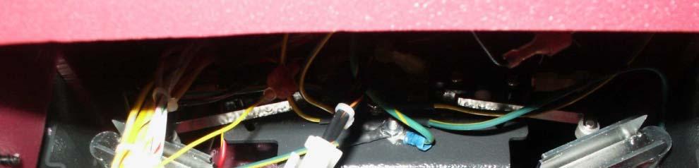
13 4. Brush Pressure Settings The brush pressure range can be changed when changing the type of deck on the SC2832E, SC2426P, CP2832 and ES2832 models. Connect the orange/violet wire into the terminal block with red/black wire group for cylindrical decks and unplug it for the disk decks. The terminal block is located below the Trio controller on the SCVs and below the control panel on the ES Trio Controller Page 13 SCV 2832E Shown

 will not require changing the settings.")

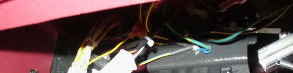
14 4.1 ES2832,CP2832, and Phoenix 34 It is now available to change the brush pressure settings in the field, when changing brush decks on current production models of the Easy Scrub 28 and 32. No other modifications will be required. Changing the brush pressure settings will only be required, when changing the cylindrical over to the disk deck or disk over to the cylindrical decks. Changing the size only (Example: Changing the 28 disk to 32 disk) will not require changing the settings. The orange/violet wire from the controller has been added to change settings. Connecting the orange/violet wire to the terminal block puts it in the low-pressure mode for cylindrical decks. Disconnecting the orange/violet from the terminal block puts the brush pressure in the high-pressure mode for disk decks. Instructions: 1. Remove the switch panel, by removing the four screws. 2. Locate the terminal block. See Photograph. Page 14
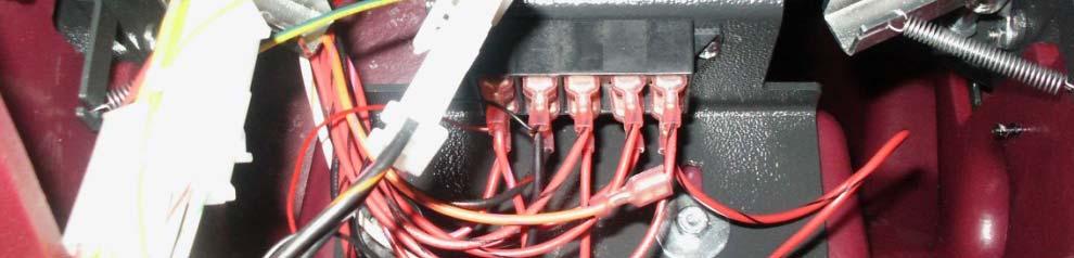
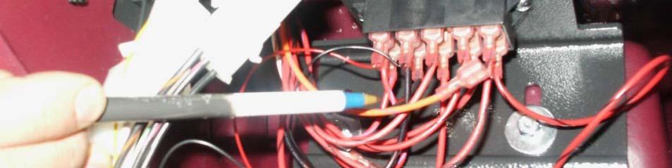
15 4.2 ES2832,CP2832, and Phoenix 34 Locate the Red/Black wire group Locate the Orange/Violet wire Page 15

16 5. Error Codes The model SC Rider scrubber uses a LCD display mounted above the steering wheel which indicates the error code when they occur. The will be displayed as a four digit code with a picture of a wrench next it. The top three are the hour meters for Total Time, Brush Motors and Drive Motor. The SC2832E, SC2426P, ES2862 and CP2832 models uses a 10 light LED display to indicate the battery condition a error codes. The battery condition will be displayed with 1 to 10 LEDS. 10 LEDs would be a fully charged battery one LED batteries are discharged. When a error occurs 1 to 10 LEDS will flash indicating a specific error has occurred. There are two aspects of the error codes. A. How many LEDS are flashing B. How many times it is flashing ( referred to as sequence) Page 16
17 6. Table of Error Codes Code Information or Fault Description Comments and Corrective Action 0810 TILLER FAULT-1 For all Throttle Potentiometer Circuit Diagnostic Codes: 0811 TILLER MAX WIPER DIFFERENCE ERROR 1- Check throttle wiring for shorts or opens. Repair or replace as necessary TILLER MAX PULL DOWN DIFFERENCE ERROR 2- If Diagnostic Code is not cleared, then replace throttle TILLER MAX PULL SAFE DIFFERENCE ERROR " " " " 0814 TILLER REFERENCE ERROR Throttle displaced during start up. Check throttle springs (Riders) or drive switches (ES or CPs) 0815 TILLER LO REFERENCE ERROR 1- Check throttle wiring for shorts or opens. Repair or replace as necessary TILLER HI REFERENCE ISO ERROR 2- If Diagnostic Code is not cleared, then replace throttle TILLER LO REFERENCE ISO ERROR " " " " 0818 TILLER ERROR BOTH HAVE READINGS " " " " 1310 EXCESSIVE CURRENT TRIP Current draw of all output devices connected to TRIO+ exceeded 250 amp maximum limit SOFT AUX1 OVERCURRENT OCCURRED Brush Actuator on Aux-1 exceeded 21 amp max. current limit. Check wiring or replace device SOFT AUX2 OVERCURRENT OCCURRED Squeegee Actuator on Aux-2 exceeded 21 amp max. current limit. Check wiring or replace device SOFT AUX3 OVERCURRENT OCCURRED Water Pump on Aux-3 exceeded 7 amp max. current limit. Check wiring or replace device SOFT AUX4 OVERCURRENT OCCURRED Water Solenoid on Aux-4 exceeded 7 amp max. current limit. Check wiring or replace device SOLUTION TANK EMPTY Solution Tank Empty signal from float switch 131C SOFT ALARM OVERCURRENT OCCURRED Alarm circuit exceeded 2 amp max. current limit. Check wiring or replace device AUX1 OVERCURRENT 2 OCCURRED Device connected to Aux-1 exceeded 12 amps for >.1 sec Check Brush Actuator AUX2 OVERCURRENT 2 OCCURRED Device connected to Aux 2 exceeded 12 amps for >.1 sec. Check wiring or replace device ERROR AUX 1 POSITIVE SHORTED_LOW Check Brush Actuator Motor and wiring. Repair or replace as necessary ERROR AUX 1 NEGATIVE SHORTED LOW Check Brush Actuator Motor and wiring. Repair or replace as necessary ERROR AUX 2 POSITIVE SHORTED LOW Check Squeegee actuator and wiring. Repair or replace as necessary ERROR AUX 2 NEGATIVE SHORTED LOW Check Squeegee actuator and wiring. Repair or replace as necessary BRAKE FAULT OPEN CIRCUIT Check Electric Brake circuit for a faulty connection BRAKE FAULT 2 Check Electric Brake circuit for a faulty connection BRAKE OVER CURRENT ERROR Check Brake circuit wiring and brake. Repair or replace as necessary HIGH BATTERY ERROR Battery is overcharged or damaged. Replace battery. 1D02 FRONT END SPEC CHANGE TRIP Drive parameters have been reprogrammed. Cycle power with key switch. Page 17 1E03 INHIBIT ACTIVATED Solution Tank Empty - Check float switch 1E04 INHIBIT ACTIVATED2 Recovery Tank Full - Check float switch 1E06 INHIBIT INPUT OUT OF RANGE Invalid Inhibit signal. Check wiring and device. Repair or replace as necessary.
18 6. Table of Error Codes 2C00 LOW BATTERY ERROR Battery Charge to low. Recharge battery. 2C01 LOW BATTERY ERROR2 Battery Charge to low. Recharge battery. 2C02 SOFT BATTERY LOCKOUT OCCURRED Battery Charge to low. Recharge battery. 2C03 SOFT BATTERY LOCKOUT 2 OCCURRED Battery Charge to low. Recharge battery. 2F01 TILLER DISPLACED ERROR Throttle displaced on Power-up. Release throttle and then re-engage throttle. 3A00 BAD SETTINGS Illegal program parameter settings STARTUP WITH PUSH SELECTED Freewheel Input signal detected at startup. Disconnect Freewheel input PUSH ACTIVATED IN DRIVE MODE Freewheel Input signal activated while driving. Disconnect Freewheel input TILLER COMMS TIMEOUT Problem with LCD Module or wiring. Repair or replace as necessary SOFT BRUSH MOTOR DISCONNECTED ERROR Check Brush Motor wiring and connectors 7601 SOFT BRUSH CURRENT FOLDBACK Too much Brush Pressure/Current. Check for jammed Brushes or Deck or Brush motor short SOFT BRUSH CURRENT FOLDBACK2 Too much Brush Pressure/Current. Check for jammed Brushes or Deck or Brush motor short SOFT BRUSH CURRENT FOLDBACK3 Too much Brush Pressure/Current. Check for jammed Brushes or Deck or Brush motor short SOFT BRUSH INHIBIT Brush Inhibit signal is active BRUSH STARTUP OVERCURRENT DETECTION Possible Brush motor problem or shorted brush circuit wiring SOFT VACUUM MOTOR DISCONNECTED ERROR Check Vacuum Motor wiring and connectors 7701 SOFT VACUUM CURRENT FOLDBACK Too much Vac motor current. Check for shorted Vac motor or wiring SOFT VACUUM CURRENT FOLDBACK2 Too much Vac motor current. Check for shorted Vac motor or wiring SOFT VACUUM CURRENT FOLDBACK3 Too much Vac motor current. Check for shorted Vac motor or wiring TRACTION MOTOR FAULT-1 Check Traction Motor wiring and connectors 7801 TRACTION MOTOR OVER CURRENT ERROR Too much Traction motor current. Check for shorted Traction motor or wiring TRACTION MOTOR IN FOLDBACK STATE Traction Motor was overloaded for too long, Control limiting current to protect motor MOTOR LINE VOLTAGES INSTABILITY TIMEOUT Possible Traction Motor or loose wiring problem TRACTION MOTOR IN DRIVE BOOST Traction Motor under heavy load or Current Limit / Fold back parameters set too low TRACTION SPEED INPUT OUT OF RANGE Check Throttle Potentiometer and wiring EMERGENCY STOP ERROR Emergency Stop function activated SOFT BELLY BUTTON ACTIVATED Safety Bar switch is activated. (ES and CP models only) 8000 SERVICE MODE Service Timer limits have been reached BRUSHES NOT FITTED Check Brush Deck to make sure Brushes are fitted properly. Page 18
19 6. Table of Error Codes 0003 For All of these Diagnostic Codes: Turn Off Key switch and disconnect batteries Wait 1 minute Reconnect Batteries and turn on key switch If Diagnostic Code is not cleared, then replace TRIO+ / TRIO+HD control. 0A01 0B02 IMPORTANT! 0B0B TRIO+ / TRIO+HD can be damaged internally by shorting Batt+ to any of it's Inputs or Outputs. Check Wiring Harness for shorts before installing a replacement Control If replacement control fails, then replace Wiring Harness before installing any more Controls B20 1B D Shorted Circuit Check For Shorts on the Brush and Drive Motor Circuits. Also Water inside of motors Page 19
20 6. Table of Error Codes 3212 For All of these Diagnostic Codes: Turn Off Key switch and disconnect batteries Wait 1 minute. 3- Reconnect Batteries and turn On Key switch If Diagnostic Code is not cleared, then replace TRIO+ /TRIO+HD control IMPORTANT! 360A 360B TRIO+ / TRIO+HD can be damaged internally by shorting Batt+ to any of it's Inputs or Outputs. Check Wiring Harness for shorts before installing a replacement Control. 360C If replacement control fails, then replace Wiring Harness before installing any more Controls. 360D 360E Page
21 5.1 Table Error Codes (LED) Single flash Low Batteries- Charge the batteries Single flash Traction drive motor disconnected Single flash - Brush motor disconnected Single flash - Brush actuator overload Two flash Squeegee actuator overload Page 21
22 5.1 Table Error Codes (LED) Single flash Vacuum motor disconnected Single flash- Off Isle Wand Activated Single flash- Potentiometer fault Single flash- Control fault check all connections to controller- see Trouble Shooting the Code 8 Error Page 22
23 5.1 Table Error Codes (LED) Single Flash- Solution tank empty- py Riders only Two flash-not used Three flash-water solenoid fault Four flash-water pump fault Five flash Electric brake circuit fault Check all connection to Five flash-electric brake circuit fault- Check all connection to the brake. Page 23
24 5.1 Table Error Codes (LED) Single flash- High battery voltage- Check all connections Ripple-Throttle activated during start up. Page 24


25 6. Side Squeegee Adjustment SCV2426 & SCV2832E Only The side squeegees on the cylindrical decks can be adjusted by loosening the two black knobs and moving the squeegee assemble up or down. The brush assembly may be accessed by removing the yellow knob C. The squeegee assembly is hinged at D. Cylindrical Decks B E Remove the three wing nuts that mount the brush idler bearing assembly E and remove the brush roll. Repeat the process on both sides of the machines A-Side Squeegee B-Black Adjustment Knob C-Yellow Brush Access Knob D-Side Squeegee Hinge E-Bush Access Plate Page 25


26 6.1 Side Squeegee Adjustment SCV2426 & SCV2832E Only The side squeegee assemblies can be adjusted by loosening the two wing nuts and moving the assembly up or down. Repeat the process on both sides, if needed. Disk Decks Squeegee Assembly Wing Nuts Wing Nuts Page 26


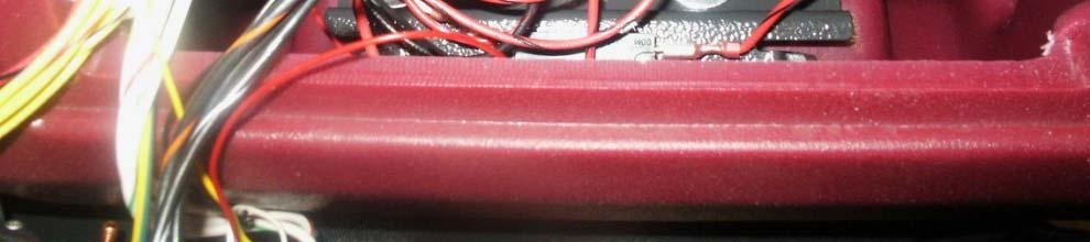
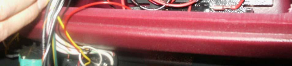
27 7. Squeegee Adjustment Later Models Only The pitch of the squeegee can be adjusted by turning the knob. Loosen the wing nuts before adjusting. Tighten the wing nuts to lock into position. Wing Nuts Adjustment Knob Page 27
28 7. Rear Squeegee Adjustment Later Models Only Page 28

29 7. Rear Squeegee Adjustment Later Models Only Page 29
30 8. Replacing the Brush Actuator on the SCV 28 or 32 All Versions Of SCV2832E and SC Replacing the Brush Actuator on the SCV 28 or Lower the brush deck, so it gently rests on the floor. 2. Remove the side squeegees. 3. Remove the four bolts that mount the deck to the lift linkage. 4. Unplug the electrical connector and the Quick Connector for the solution from the deck. 5. Slide the deck out from under the machine. 6. Unplug the electrical connector to the actuator motor. 7. Remove the two pins that mount the actuator on each end. 8. Remove the actuator from the machine. 9. Mount the new actuator. Do not connect the electrical connector on the actuator at this point. 10. Connect the battery pack. 11. Turn the machine on. 12. Put the machine in Service Mode. Hold one of the brush pressure buttons on the touch pad for over 20 seconds and release on the model SC The SC28/32E s service mode switch is located in the controller compartment under the seat, on the operators left side. Push the rocker switch in the down position for 20 seconds. 13. Connect the actuator electrical connector into the harness. 14. Use the up and down buttons on the touch pad to adjust the brush linkage height, so that you can slide the brush deck into position. Do not raise it all the way up, until it is set correctly. 15. Lower the linkage down, using the touch pad or rocker switch, so that it gently rests on the mounting brackets. Page 30
31 8. Replacing the Brush Actuator on the SCV 28 or 32 All Versions Of SCV2832E and SC Slide the brush deck into position, install the four mounting bolts and tighten. Connect the brush motor connector and solution quick connector. 17. Locate the black rubber removable plug on the right side of the actuator t and remove. 18. For models with cylindrical decks only. Remove the plastic side deck cover on the operators left side. This is a gray plastic piece screwed to the side of the solution tank above the deck area. 19. Use the brush pressure up button to raise it up a little at a time. The clearance between the top belt cover and the under side of the tank should between 1/4 to 3/8 inch, when the deck stops rising up. Do not allow it to rise any higher h or it might over load the actuator. t If it continues to rise higher, h adjustment t will be required. 20. For Disk machines only, the actuator should be set so that you can slide the brushes under the deck and not bottom out under the machine. 21. Adjust the actuator adjustment screw to change setting see drawing. Turn the screw no more than 1/8 of a turn at a time. The adjustment t screw closest to the shaft controls how high h it rises. The screw furthest t from movable controls maximum down pressure. Look at the rubber plug to determine which way to turn the screw. 22. Lower the brush deck and return it back up for the new settings to change. 23. Adjust the down setting so that the actuator cannot lift the drive motor off the floor. Set it so it only lifts some pressure off the drive wheel. 24. Once the correct setting is made replace the rubber plug into the side of the actuator motor. 25. Replace side plastic cover. 26. Turn the key switch off and back on. 27. Test the machine. Page 31
32 8.1 Actuator Adjustment Page 32
33 8.2 Entering Service Mode with a Stuck Actuator Page 33
34 9. Trouble Shooting the Code 8 Error ES2832, CP2832, SCV2426 and SC2832E Models Only) 1. Check for loose or burnt connections on the controller, batteries, cables and the circuit breaker. Make the sure the circuit breaker is not damaged. 2. Measure the total battery voltage at the batteries and at the battery connections on the controller. They should be exactly the same. A 1/10 of a volt or more difference would indicate a problem in the connections. 3. Check to see, if the operator has recently washed the machine down and got water inside of the brush motor or in the controller area. 4. On the ES2832 and CP2832 only disconnect the plug on the Service Mode Switch. This is accessible by tilting the solution tank forward. Power the machine up with it disconnected. If error code is cleared replace the switch. 5. Check for a disconnected or an open circuit or faulty potentiometer on the throttle or speed circuit. Controller may not be detecting it in the circuit. Do a continuity test. See Testing the potentiometer section. Page 34
35 9. Trouble Shooting the Code 8 Error 6. Disconnect one motor connector from the Trio controller at a time and disconnect the batteries for 1 minute and restart the machine. If the code 8 disappears and is replaced by a different code, the circuit disconnected should be considered suspect. For example the brush was disconnected. The code 8 is replaced by code 3. Code 3 indicates the brush motor is disconnected. Check for a loose or broken connection at the brush deck. Check to see if water has gotten inside the brush motor. Check for a shorted motor. 7. Static electricity. Check both the ground chains; there is one on the brush deck and one on the rear of the machine. They should be contacting ti the floor. The one on the deck should touch the floor when the deck is down. They also should have continuity between the end of the chain and the frame of the machine. Repair or clean if needed if needed. 8. If everything checks OK, replace the Trio Controller. Note controllers can be damaged by loose connections on inputs and outputs, static electricity and water on electrical components such as on or in the controller and motors. Page 35
36 10. Testing the Throttle Potentiometer 1. The throttle potentiometer resistance can be measured with an ohmmeter. 2. Unplug the throttle potentiometer at the connector next to it. 3. Analog type meters are recommended for this test. 4. Measure the resistance across the red and white wire on the potentiometer assembly. It should measure approximately 5K (5 thousand ohms). 5. Measure across the black and white wires on the potentiometer, the resistance should be zero ohms with pedal on the riders in the neutral position or speed knob on the ES2832 and CP2832 in the full counterclockwise position. When the pedal or knob is moved to the full throttle position, in should be a smooth resistance change without dropping out. It should measure approximately 5K (5 thousand ohms) in the full position. 6. Measuring across the black and the red wire the resistance should be approximately 5K (5 thousand), when in the neutral position. When the pedal is at full throttle or the knob is full speed position, the resistance should drop to zero. 7. If adjustment is needed, loosen the nut and screw on the throttle arm. Adjust the potentiometer shaft with a flat tip screw driver, until it is set according to the information above (on the riders only). Potentiometer Assembly Adjust Here Page 36
37 10. Testing the Throttle Potentiometer 8. If they do not find a problem here, have them retest at the connector at the Trio controller. 9. Reconnect the plug at the throttle potentiometer. 10. Unplug the P3 connector (The large white connector) on the controller under the seat on the riders and behind the two rear panels on the ES2832s and CP2832s. 11. Locate the black/orange and the black/pink k wire. 12. Measuring across the black/orange and black/pink wires the resistance should be zero ohms in the neutral position. It should 5k in the full throttle position. 13. Measure across the black/pink and the black/white wires. The resistance should be 5K (5 thousand) in the neutral position. When the pedal is at full throttle the resistance should drop to zero. 14. If your reading is different with this test check all the connections between the controller and the throttle control, including the seat switch. Note: when moving the throttle to the full position, the resistance should be smooth, without dropping out for both tests. If the resistance does not go to 5K during the test, the arm and the potentiometer may need to be adjusted to achieve it. Page 37
38 11. Identifying the Cause of Trio Failures 1. Check for loose or burnt connections on the controller, batteries, cables and the circuit breaker. Make the sure the circuit breaker is not damaged (burnt or cracked). 2. Test the chassis drive motor harness for broken wires (riders only). Disconnect the plug labeled Traction on the Trio controller. Connect a digital multi-meter to the plug on the two large wires. Set the meter for Ohms (resistance). The resistance should be.3 to.4 ohms. Turn the steering wheel in both directions until it stops several times. Monitor the meter while turning. The resistance should not change or vary while turning. Any variation even.1 ohm would be indicate a broken wire, which could cause spikes and surges, that could damage the Trio controller. 3. Measure the total battery voltage at the batteries and at the battery connections on the controller. They should be exactly the same. A 1/10 of a volt or more difference would indicate a problem in the connections. Page 38
39 12. Notes Page 39
Service Manual. Extractor Model XR28QP. For The. For: Troubleshooting Adjustments
 Service Manual For The X Ride 28 Rider Extractor Model XR28QP For: Training Troubleshooting Adjustments Contents 1 Cautions ------------------------------------------------------------------------------
OPERATION MANUAL CHAMP 3529 RB IMPORTANT SAFETY INSTRUCTIONS
 OPERATION MANUAL CHAMP 3529 RB IMPORTANT SAFETY INSTRUCTIONS WARNING: Failure to observe these instructions can cause personal injury to machine operator or bystanders. WARNING: Fire or explosion hazard.
i-drive, i45 & i90 DIAGNOSTIC GUIDE
 , i45 & i90 DIAGNOSTIC GUIDE If the Programmer displays Unrecognized Error, this is probably because the Programmer software needs upgrading to include the Help Text for that Error Code. Please refer to
ES 2832 WALK-BEHIND SCRUBBER OPERATION SERVICE PARTS CARE
 ES 2832 WALK-BEHIND SCRUBBER OPERATION SERVICE PARTS CARE This manual is furnished with each new MINUTEMAN ES TM 2832. This provides the necessary operating and preventive maintenance instructions. Operators
Electronic Service Manuals
 Electronic Service Manuals This electronic document is provided as a service to our customers. We do not create the contents of the information contained in this document. Should you have detailed questions
NILFISK BA 500 Service Manual
 NILFISK BA 500 Service Manual Model 66324400 12/94 Form Number 043023 TABLE OF CONTENTS Batteries...21 Brush Drive Belt Adjustment Or Replacement...7 Brush Drive Motor - Carbon brush Inspection... 8 Brush
OPERATION MANUAL CHAMP 3329 RB IMPORTANT SAFETY INSTRUCTIONS
 OPERATION MANUAL CHAMP 3329 RB IMPORTANT SAFETY INSTRUCTIONS WARNING: Failure to observe these instructions can cause personal injury to machine operator or bystanders. WARNING: Fire or explosion hazard.
OPERATION MANUAL ORIGINAL INSTRUCTIONS CHAMP 2929 RB IMPORTANT SAFETY INSTRUCTIONS
 OPERATION MANUAL ORIGINAL INSTRUCTIONS CHAMP 2929 RB IMPORTANT SAFETY INSTRUCTIONS WARNING: Failure to observe these instructions can cause personal injury to machine operator or bystanders. WARNING: Fire
User s Manual. Automatic Switch-Mode Battery Charger
 User s Manual Automatic Switch-Mode Battery Charger IMPORTANT Read, understand, and follow these safety rules and operating instructions before using this battery charger. Only authorized and trained service
Quickie Rhapsody Service Manual
 Quickie Rhapsody Service Manual 2006 Sunrise Medical Inc. 101976 Rev A Quickie Rhapsody Service Manual Contents Introduction... 0.1 VR2 Controller... 0.2 Plugs/Connectors... 0.3 Basic Tool List & Main
C.E. Niehoff & Co. C653/C653A and C625 Alternators Troubleshooting Guide NOTICE. Hazard Definitions. Battery Charge Volt and Amp Values
 C.E. Niehoff & Co. C653/C653A and C625 Alternators Troubleshooting Guide Hazard Definitions These terms are used to bring attention to presence of hazards of various risk levels or to important information
S-DRIVE CONTROLLER DIAGNOSTIC BLEEP CODES
 S-DRIVE CONTROLLER DIAGNOSTIC BLEEP CODES 1 * Not Used 2 ** Low Battery Voltage 3 *** High Battery Voltage 4 **** Not Used 5 ***** Solenoid Brake Trip (free-wheel) 6 ****** Throttle/speed pot Trip 7 *******
N1387 Series Troubleshooting Guide for N Alternators
 N1387 Series Troubleshooting Guide for N1387-1 Alternators Hazard Definitions These terms are used to bring attention to presence of hazards of various risk levels or to important information concerning
4.2 Component Identification
 Digital Control Panels Deep Sea Electronics 5220 4.1 General 4.2 Component Identification 4.3 The YML5220 Controller 4.4 Description of Controls 4.5 Navigation 4.5.1 General Navigation 4.5.2 The Event
 Page 1 of 29 Section 04-05: Suspension, Computer Controlled 1997 Town Car Workshop Manual DIAGNOSIS AND TESTING Procedure revision date: 05/16/2000 Suspension, Computer Controlled Inspection and Verification
Application Engineering
 Application Engineering February, 2009 Copeland Digital Compressor Controller Introduction The Digital Compressor Controller is the electronics interface between the Copeland Scroll Digital Compressor
ELECTRICAL. Contents - Wiring Diagrams
 Contents - Wiring Diagrams T-Bar (Floating Deck - Hydro)............................................ 8-16 T-Bar (Fixed Deck - Gear)............................................... 8-17 T-Bar (Fixed Deck
Battery Control Center - Diesel
 Service Manual CAUTION: All servicing of the Battery Control Center should be done only by a qualified Service Technician. Inadvertent shorts inside the Battery Control Center could result in severe damage
WARRANTY WILL BE VOID If These Steps are Not Performed Before Installing The Control STEPS TO PERFORM BEFORE CONTROL INSTALLATION
 Curtis 1268-5411 This sheet is provided to aid in the installation of your remanufactured CURTIS controller. Upon installation, you may encounter problems that may, or may not, be due to a faulty controller.
SYMPTOM POSSIBLE CAUSES CORRECTIVE ACTION. Batteries Battery connections
 ELECTRICAL SYSTEM AND TESTING TROUBLESHOOTING GUIDE 2 Troubleshooting 11 TROUBLESHOOTING GUIDE 2 SYMPTOM POSSIBLE CAUSES CORRECTIVE ACTION Vehicle does not operate Batteries Batteries discharged Charge
VEHICLE SPEED CONTROL SYSTEM
 J VEHICLE SPEED CONTROL SYSTEM 8H - 1 VEHICLE SPEED CONTROL SYSTEM CONTENTS page DIAGNOSIS... 2 GENERAL INFORMATION... 1 page SERVICE PROCEDURES... 9 GENERAL INFORMATION The vehicle speed control system
User Manual. Phoenix 20 Floor Scrubber Traction Drive
 User Manual Phoenix 20 Floor Scrubber Traction Drive This manual is furnished with each new PowerBoss Phoenix 20. This provides the necessary operating and preventive maintenance instructions. Operators
SCOOTER CONTROLLER FAULT CODES
 Flash Code 1 Fault Description Battery Needs Recharging Actions The battery voltage has dropped below 23.3V in neutral. Recharge the batteries soon. Remember Our Graph? 100 90 80 70 60 50 40 30 20 10 0
CRUISE CONTROL SYSTEM
 CRUISE CONTROL SYSTEM 1993 Mitsubishi Montero 1993 ACCESSORIES & EQUIPMENT Mitsubishi Cruise Control Systems Montero DESCRIPTION & OPERATION The cruise control system is electronically and vacuum controlled.
Application Engineering
 Application Engineering March 2011 Copeland Digital Compressor Controller Introduction The Digital Compressor Controller is the electronics interface between the Copeland Scroll Digital compressor or the
PRODUCT INFORMATION BULLETIN #3365 DIGITAL MOTOR CONTROL PLATTER SYSTEMS For Serial Number and After
 PRODUCT INFORMATION BULLETIN #3365 DIGITAL MOTOR CONTROL PLATTER SYSTEMS For Serial Number 28640996 and After Record Platter System Identification Numbers Here: Model # Serial # Table of Contents Program
INSTALLATION MANUAL SPECTRUM BRAKE CONTROL
 INSTALLATION MANUAL 51170 SPECTRUM BRAKE CONTROL TABLE OF CONTENTS Controls & Components Tools List Before You Begin Wiring Wiring Diagram Mounting the LED Display Rotary Knob Wiring the Plug Connector
DESCRIPTION & OPERATION
 DESCRIPTION & OPERATION 1998-99 SUSPENSION Electronic - Real Time Damping - Corvette The Real Time Damping (RTD) system automatically controls vehicle ride by independently controlling a damper solenoid
SC1500. Service Manual. Advance SC1500 Models: (X20D), (X20R) Nilfisk SC1500 Models: (SC D) English
, (X20R) Nilfisk SC1500 Models: (SC D) English") SC1500 Service Manual Advance SC1500 Models: 56104000 (X20D), 56104001 (X20R) Nilfisk SC1500 Models: 56104002 (SC1500-51D) English 5/2013 Revised 11/2017, Form No. 56043166 ii Contents General Information
SC1500 Service Manual Advance SC1500 Models: 56104000 (X20D), 56104001 (X20R) Nilfisk SC1500 Models: 56104002 (SC1500-51D) English 5/2013 Revised 11/2017, Form No. 56043166 ii Contents General Information
POWER DOOR LOCKS 8P - 1 POWER DOOR LOCKS CONTENTS
 PL POWER DOOR LOCKS 8P - 1 POWER DOOR LOCKS CONTENTS POWER DOOR LOCKS... 1 REMOTE KEYLESS ENTRY... 3 POWER DOOR LOCKS INDEX INTRODUCTION... 1 DOOR LOCK MOTOR... 1 DOOR LOCK SWITCH... 1 INTRODUCTION All
User Manual. H20 Walk-Behind Scrubber Disc Traction Drive
 User Manual H20 Walk-Behind Scrubber Disc Traction Drive This manual is furnished with each new MINUTEMAN H20. This provides the necessary operating and preventive maintenance instructions. Operators must
WORKSHOP HANDBOOK MXR
 WORKSHOP HANDBOOK MXR Version: AA Date: January 15, 2014 Document Number:10045983/ATE Contents I Product Introduction 4 1 Serial Number and Technical Support 5 1.1 The Serial Tag.................................
User Manual Solar Charge Controller 3KW
 User Manual Solar Charge Controller 3KW Version: 1.3 CONTENTS 1 ABOUT THIS MANUAL... 1 1.1 Purpose... 1 1.2 Scope... 1 1.3 SAFETY INSTRUCTIONS... 1 2 INTRODUCTION... 2 2.1 Features... 2 2.2 Product Overview...
1999 Toyota RAV ACCESSORIES & EQUIPMENT Cruise Control Systems - RAV4
 1999 ACCESSORIES & EQUIPMENT Cruise Control Systems - RAV4 DESCRIPTION WARNING: Deactivate air bag system before performing any service operation. See AIR BAG RESTRAINT SYSTEMS article. DO NOT apply electrical
VAGABOND S HANDBOOK TRANSMISSION
 03/24/07 TRANSMISSION Transmission won t engage into Gear This is caused usually by too low a Voltage to get into the ECM. This unit requires a minimum of 9VDC in order to operate at all. Almost all erratic
KE-4 Installation/Operation Instruction Manual FT033
 KE-4 Installation/Operation Instruction Manual FT033 Electronic Control System Electronic Control System Thumb Tab Guide Trolling Module Handheld Control Engine Synchronization Trolling Module Handheld
C.E. Niehoff & Co. N1601, N1602, N1603, and N1604 Alternator Troubleshooting Guide NOTICE. Hazard Definitions. Battery Charge Volt and Amp Values
 C.E. Niehoff & Co. N1601, N1602, N1603, and N1604 Alternator Troubleshooting Guide Hazard Definitions These terms are used to bring attention to presence of hazard(s) of various risk levels or to important
Installation and Operating Instructions
 Installation and Operating Instructions Congratulations on your purchase of a Franklin Electric pump protection system. Pumptec-Plus is the most sophisticated pump protection system on market today. It
Parts and Instructions Manual SCV 28/32 Rider Scrubber
 Parts and Instructions Manual SCV 28/32 Rider Scrubber This manual is furnished with each new MINUTEMAN SCV TM 28/32. This provides the necessary operating and preventive maintenance instructions. Operators
TrailerTail does not open at all (one or both sides) TrailerTail does not latch closed... 5
 TrailerTail does not latch closed... 5") This is a step-by-step guide to diagnose and repair the most common AutoDeploy field issues. If at any time you would like direct phone support, please call STEMCO Customer Support at 888-283-8245 x2.
This is a step-by-step guide to diagnose and repair the most common AutoDeploy field issues. If at any time you would like direct phone support, please call STEMCO Customer Support at 888-283-8245 x2.
SECOND GENERATION Use this guide with unit serial number prefix beginning with BWF using Terra Power separator.
 Technical Information and Diagnostic Guide for SECOND GENERATION Use this guide with unit serial number prefix beginning with BWF using Terra Power separator. This guide will assist you in becoming more
CHEMICAL MIXING SYSTEM OPERATING AND INSTALLATION INSTRUCTIONS
 Chemical Mixing System Operating and Installation Instructions for Focus II Mid-Size Walk-Behind Kit #11363A CHEMICAL MIXING SYSTEM OPERATING AND INSTALLATION INSTRUCTIONS TOOLS REQUIRED: Phillips Screwdriver
Go Yonder D-Lite Owner s Manual
 Go Yonder D-Lite Owner s Manual Marketed in Australia and New Zealand by Bzooma Pty Ltd ABN 37 640 907 507 TABLE OF CONTENTS Table of Contents... 1 Bzooma Pty Ltd... 1 Introduction... 1 Operation... 1
PowerLevel s e r i e s
 Owner s Manual Hydraulic Leveling CONTENTS Introduction Operation Control Panel Automatic Leveling Manual Leveling Retracting Jacks Remote Operation Care & Maintenance Troubleshooting Error Codes 1 2 2
CRUISE CONTROL SYSTEM
 CRUISE CONTROL SYSTEM 1992 Infiniti G20 1991-92 SAFETY EQUIPMENT Infiniti Cruise Control Systems G20, M30, Q45 DESCRIPTION & OPERATION NOTE: For system component locations, see SYSTEM COMPONENT LOCATIONS.
1991 Mazda MX-5 Miata AIR BAG RESTRAINT SYSTEM MAZDA AIR BAGS
 DESCRIPTION & OPERATION AIR BAG RESTRAINT SYSTEM MAZDA 1990-91 AIR BAGS WARNING: To avoid injury from accidental air bag deployment, read and carefully follow all WARNINGS and SERVICE PRECAUTIONS. The
Installation and Operating Instructions
 PUMP PROTECTION SYSTEM Installation and Operating Instructions Congratulations on your purchase of a Franklin Electric pump protection system. Pumptec-Plus is the most sophisticated pump protection system
ANTI-LOCK BRAKE SYSTEM - REAR WHEEL
 ANTI-LOCK BRAKE SYSTEM - REAR WHEEL 1994 Nissan Pickup 1994 BRAKES Nissan - Rear Anti-Lock Pathfinder, Pickup DESCRIPTION In 2WD mode, Rear Anti-Lock Brake System (RABS) helps the driver to maintain steering
Installation Operation Parts
 OWNER S MANUAL BATTERY BACKUP SUMP Installation Operation Parts For further operating, installation or maintenance assistance, Call 98-8-05 PRINTED IN U.S.A. M-8 (/9) RULES FOR SAFE INSTALLATION AND OPERATION
STARTING SYSTEMS 8B - 1 STARTING SYSTEMS CONTENTS
 TJ STARTING SYSTEMS 8B - 1 STARTING SYSTEMS CONTENTS page DESCRIPTION AND OPERATION STARTER MOTOR... 2 STARTER RELAY... 3 STARTING SYSTEM... 1 DIAGNOSIS AND TESTING STARTER MOTOR... 8 STARTER MOTOR NOISE
Service Manual Gulf Stream Electronic Full Wall Slide Systems
 Service Manual Gulf Stream Electronic Full Wall Slide Systems CONTENTS Page Before you operate the slide system 2 Operating Instructions 3 Preventive maintenance 3 Manually overriding your slide system
Subject Underhood G System Error Codes and Symptoms System or Parts affected
 System or Parts affected Index Underhood70G (V90Gxxx) System or Parts affected... 1 Overview... 1 Identifying your System... 1 Retrieving Logged Error Messages... 1 Error Messages... 3 Error Message Table...
2001 Dodge Durango ACCESSORIES & EQUIPMENT' 'Anti-Theft Systems - Dakota & Durango 2001 ACCESSORIES & EQUIPMENT
 DESCRIPTION VEHICLE THEFT SECURITY SYSTEM 2001 ACCESSORIES & EQUIPMENT Anti-Theft Systems - Dakota & Durango Vehicle Theft Security System (VTSS) provides perimeter protection against unauthorized use
SCV 24/26 RIDER SCRUBBER OPERATION SERVICE PARTS CARE
 SCV 24/26 RIDER SCRUBBER OPERATION SERVICE PARTS CARE This manual is furnished with each new MINUTEMAN SCV TM 24/26. This provides the necessary operating and preventive maintenance instructions. Operators
User Manual. PHX26ECO Walk-Behind Scrubber Traction Drive Disc Deck
 User Manual PHX26ECO Walk-Behind Scrubber Traction Drive Disc Deck This manual is furnished with each new POWERBOSS PHX26ECO. This provides the necessary operating and preventive maintenance instructions.
MDX-300 Series. For 12-volt automotive starting batteries and starting/charging systems INSTRUCTION MANUAL
 For 12-volt automotive starting batteries and starting/charging systems INSTRUCTION MANUAL Blank page Contents Caution... 4 Capabilities... 4 Display and Keypad... 4 Preparations Before the Test... 6 Connecting
CMAX 28/34ST I-MAX 28/32C BA 750/850ST, BA 750C
 CMAX 8/34ST I-MAX 8/3C BA 750/850ST, BA 750C SERVICE MANUAL Advance MODELS 5639600, 56397403, 56397400, 5639740 Nilfisk MODELS 563960, 563960, 5639740 6/0 revised /04 Form Number 5604307 GENERAL INFORMATION...
AUTOMATIC FOODSERVICE EQUIPMENT. AUTOMATIC ELECTRIC BROILER MODELS 824E & 850E and 624E & 650E. B-Series Broiler OWNER S MANUAL
 AUTOMATIC FOODSERVICE EQUIPMENT AUTOMATIC ELECTRIC BROILER MODELS 824E & 850E and 624E & 650E B-Series Broiler OWNER S MANUAL FOR YOUR SAFETY: Do not store or use gasoline or other flammable vapors or
ELECTRIC SCHEMATICS LS1 LS2. "1532ES / 1932ES" Service & Parts Manual - ANSI Specifications March 2008 Page 5-9 ART_2236 ART_2243
 ELECTRIC SCHEMATICS NOTES: (Unless otherwise specified). Switch S BASE/PLATFORM makes contact from the CENTER to the LEFT position when placed in BASE.. Switch S UP/DOWN makes contact from the CENTER to
R & D SPECIALTIES ROTROL I USER'S MANUAL
 R & D SPECIALTIES ROTROL I USER'S MANUAL TABLE OF CONTENTS INTRODUCTION...2 SPECIFICATIONS...2 CONTROLS AND INDICATORS...3 TIME DELAYS...4 INSTALLATION...5 SYSTEM OPERATION...9 TROUBLESHOOTING...13 OPTIONAL
Quickie S-11 Service Manual
 Quickie S-11 Service Manual 05 Sunrise Medical Inc. 100740 Rev A Quickie S-11 Troubleshooting Guide INTRODUCTION... 0.1 Specifications VSI Controller... 0.2 Plugs/Connectors... 0.3 Main Wiring Diagram/
SERVICE MANUAL. Kysor Instrumentation Troubleshooting Guide
 Kysor Instrumentation Troubleshooting Guide Troubleshooting Emergency One Commercial System The Medallion II instrumentation system is a Microprocessor based system utilizing both Sensor and Data bus information
OPERATING MANUAL Digital Diesel Control Remote control panel for WhisperPower generator sets
 Art. nr. 40200261 OPERATING MANUAL Digital Diesel Control Remote control panel for WhisperPower generator sets WHISPERPOWER BV Kelvinlaan 82 9207 JB Drachten Netherlands Tel.: +31-512-571550 Fax.: +31-512-571599
AFT mid drive kit Trouble shooting guide For 24v to 48V Kelly Controller KBS 48101L-L 100 A peak
 Date: 2016-13-1 AFT mid drive kit trouble shooting guide Rev 1.7 Page 1 of 17 AFT mid drive kit Trouble shooting guide For 24v to 48V Kelly Controller KBS 48101L-L 100 Table of Contents 1. Safety... 2
ADVANCED ELECTRONIC ACCELEROMETER TRAILER BRAKE CONTROL
 BRAKE CONTROL ADVANCED ELECTRONIC ACCELEROMETER TRAILER BRAKE CONTROL INSTALLATION AND USER GUIDE For use with 12 volt negative ground systems only For trailers with 2 8 brakes Read, follow and save this
AUTO CHARGE LPC SERIES
 INSTRUCTION MANUAL FILE: IM_091-206-12_revB REV: B REVISED BY: THN DATE: 09-17-2012 AUTO CHARGE LPC SERIES MODEL #091-206-12 LPC STANDARD DISPLAY INPUT: 115 volt, 50/60 Hz, 13 amps OUTPUT: 80 AMPERES 3
BRIVIS DUCTED INVERTER SERVICE MANUAL DRCi
 BRIVIS DUCTED INVERTER SERVICE MANUAL DRCi 1 TABLE OF CONTENTS TABLE OF CONTENTS... 2 IMPORTANT NOTE... 3 FAULT FINDING AND DIAGNOSTICS... 3 ABBREVIATIONS... 3 PCB S... 4 OUTDOOR MAIN PCB... 4 INDOOR PCB...
The Traveler Series: Adventurer
 The Traveler Series: Adventurer RENOGY 30A Flush Mount Charge Controller Manual 2775 E. Philadelphia St., Ontario, CA 91761 1-800-330-8678 Version: 2.2 Important Safety Instructions Please save these instructions.
99125B - Series N Brush Lift Assembly Model :99125B 20" EZ Floorkeeper (w/ 4-6 V Batteries) - Series N
 - Series N") 995B - Series N Brush Lift Assembly Model :995B 0" EZ Floorkeeper (w/ - V Batteries) - Series N Page- 5 7 9 0 5 7 9 5 7 9 0 5 7 9 0 070 RETAINING RING PIN 9 WASHER 907 WELDMENT BRUSH LIFT PEDAL 900 PEDAL
995B - Series N Brush Lift Assembly Model :995B 0" EZ Floorkeeper (w/ - V Batteries) - Series N Page- 5 7 9 0 5 7 9 5 7 9 0 5 7 9 0 070 RETAINING RING PIN 9 WASHER 907 WELDMENT BRUSH LIFT PEDAL 900 PEDAL
SERVICE MANUAL (DOMESTIC & INTERNATIONAL)
") SERVICE MANUAL (DOMESTIC & INTERNATIONAL) DUAL TECHNOLOGY FINISHER MODEL 1960 & 1980 SERIES Lincoln Foodservice Products, LLC 1111 North Hadley Road Fort Wayne, Indiana 46804 United States of America Telephone:
SERVICE MANUAL (DOMESTIC & INTERNATIONAL) DUAL TECHNOLOGY FINISHER MODEL 1960 & 1980 SERIES Lincoln Foodservice Products, LLC 1111 North Hadley Road Fort Wayne, Indiana 46804 United States of America Telephone:
Reproduction or other use of this Manual, without the express written consent of Vulcan, is prohibited.
 SERVICE MANUAL ELECTRIC BRAISING PANS (30 & 40 GALLON) VE30 VE40 ML-126849 ML-126850 VE40 SHOWN - NOTICE - This Manual is prepared for the use of trained Vulcan Service Technicians and should not be used
SOLAR LIGHTING CONTROLLER SUNLIGHT MODELS INCLUDED IN THIS MANUAL SL-10 SL-10-24V SL-20 SL-20-24V
 SOLAR LIGHTING CONTROLLER OPERATOR S MANUAL SUNLIGHT MODELS INCLUDED IN THIS MANUAL SL-10 SL-10-24V SL-20 SL-20-24V 10A / 12V 10A / 24V 20A / 12V 20A / 24V 1098 Washington Crossing Road Washington Crossing,
Service Manual Rev. 02 (3-02)
") 7200 Service Manual 330045 Rev. 02 (3-02) This service manual is intended to be an aid for the disassembly and reassembly of your TENNANT Model 7200 ride on scrubber. The set is organized into four major
7200 Service Manual 330045 Rev. 02 (3-02) This service manual is intended to be an aid for the disassembly and reassembly of your TENNANT Model 7200 ride on scrubber. The set is organized into four major
System III Wiring Information 54-12
 System III Wiring Information 54-12 System Operation General Information Initial Power On Description of Revisions: This service bulletin is updated and replaces the version dated September 2002. This
Lumina 28 Traction Drive Model: Battery Burnisher M28036TDQP OPERATION SERVICE PARTS CARE
 Lumina 28 Traction Drive Model: Battery Burnisher M28036TDQP OPERATION SERVICE PARTS CARE Table of Contents IMPORTANT SAFETY INSTRUCTIONS...1 OPERATING INSTRUCTIONS...2 INSPECTION...2 ELECTRICAL...2 BATTERIES...2
PARTS LIST CHAMP 2929
 PARTS LIST CHAMP 2929 1 ITEM PART NO. DESCRIPTION QTY. 101 9122343 3/8-16 X 2 HEX HEAD FULL THREADED BOLT 3 102 9122100 3/8 SPLIT LOCK WASHER 3 103 9121400 3/8 I.D. X 7/8 O.D. X.064/.104 THICK WROUGHT
C.E. Niehoff & Co. C703/C703A and C706 Alternators Troubleshooting Guide CAUTION. Testing Guidelines. Hazard Definitions WARNING.
 C.E. Niehoff & Co. C703/C703A and C706 Alternators Troubleshooting Guide WARNING Before troubleshooting any CEN products, the service technician should: read, understand, and agree to follow all information
ECO3-601/602 EcoStar III * Chevy Express/GMC Savana Contact Intermotive for additional vehicle applications
 An ISO 9001:2015 Registered Company ECO3-601/602 EcoStar III 2009-2019* Chevy Express/GMC Savana Contact Intermotive for additional vehicle applications * In 2017-2018, the ignition switches on Chevy Express
SECTION 2 - PROCEDURES. Features. 2.6 MOTOR CONTROLLER. Modes of Operation JLG Lift 2-5
 2.6 MOTOR CONTROLLER. Modes of Operation. 1. Traction Motor Drive. a. Drive in either forward or reverse will start only if the following conditions are satisfied: 1. Function switches off. 2. No procedure
Troubleshooting 3Z8 038 Rev B
 Troubleshooting 3Z8 038 Rev B INSTRUCTIONS WARNING INJECTION HAZARD This form is only a quick reference for troubleshooting Graco sprayers. To reduce the risk of serious injury, including fluid injection,
Smart 110 with built-in flashlight for 6 240Ah lead-acid batteries
 USER GUIDE Battery Charger Smart 110 with built-in flashlight for 6 240Ah lead-acid batteries Please read this user guide carefully before using the charger Use protective eyewear when handling batteries
User Manual. Solar Charge Controller 3KW
 User Manual Solar Charge Controller 3KW 1 CONTENTS 1 ABOUT THIS MANUAL... 3 1.1 Purpose... 3 1.2 Scope... 3 1.3 SAFETY INSTRUCTIONS... 3 2 INTRODUCTION... 4 2.1 Features... 4 2.2 Product Overview... 5
Brushed. Brushed. Brushed Motor
 Kelly Kelly Kelly Kelly KD KD KD KD Series Series Series Series DC DC DC DC Motor Motor Motor Motor Controller Controller Controller Controller User User User User s Manual Manual Manual Manual V 2.5 2.5
CRUISE CONTROL SYSTEM
 CRUISE CONTROL SYSTEM 1994 Volvo 960 1994 ACCESSORIES/SAFETY EQUIPMENT Cruise Control System 960 DESCRIPTION & OPERATION MAIN SWITCH Cruise control main switch is located at end of directional signal lever.
ATOTH-G Series BLDC Motor Controller. User s Manual
 ATOTH-G Series BLDC Motor Controller User s Manual Contents Chapter One Summary...1 Chapter Two Main Features and Specifications.2 2.1 Basic Functions...2 2.2 Features... 5 2.3 Specifications...6 Chapter
 8803214-8803999 DIODE BOARD The diode board is located inside the lower control box. D15 D8 D7 D14 D5 D13 ART_2181 J1 14 8 D9 D10 7 1 R2 R1 R3 R4 TB1 8601 D11 D3 D12 D4 D1 D2 J1 Plug Pin Identification
 DIODE BOARD The diode board is located inside the lower control box. D15 D8 D7 D14 D5 D13 ART_2181 J1 14 8 D9 D10 7 1 R2 R1 R3 R4 TB1 8601 D11 D3 D12 D4 D1 D2 J1 Plug Pin Identification PIN # WIRE # SIGNAL
500 Series Troubleshooting Guide for C520 Alternators
 500 Series Troubleshooting Guide for C520 Alternators Hazard Definitions These terms are used to bring attention to presence of hazards of various risk levels or to important information concerning product
348002K/348012K Manifold Block Style Service Manual 12/2000
 348002K/348012K Manifold Block Style Service Manual 12/2000 Service Manual 348002K/348012K Manifold Block Style Recovery/Recycling/Recharging Unit For R-12 or R-134a Only TABLE OF CONTENTS: Theory of Operation
T15 *331555* Service Information Manual. North America / International Rev. 00 ( ) The Safe Scrubbing Alternative R.
 The Safe Scrubbing Alternative R.") T15 Service Information anual The Safe Scrubbing Alternative R North America / International www.tennantco.com 331555 Rev. 00 (05-2007) *331555* A B FOR REPLACEENT PARTS Identify machine model and serial
T15 Service Information anual The Safe Scrubbing Alternative R North America / International www.tennantco.com 331555 Rev. 00 (05-2007) *331555* A B FOR REPLACEENT PARTS Identify machine model and serial
Installation, Operation and Maintenance Manual
 Document 473681 Vari-Green Motor and Controls Installation, Operation and Maintenance Manual Please read and save these instructions for future reference. Read carefully before attempting to assemble,
Troubleshooting Manual
 Troubleshooting Manual NOTICE: DO NOT DISCARD THIS MANUAL Models: LEGACY42-IFT PHOENIX42-IFT 1 TABLE OF CONTENTS A. Normal Operation...3 B. Wiring Diagram...4 C. Troubleshooting IntelliFire Touch...5 D.
N1233 Series Troubleshooting Guide for N Alternator
 N1233 Series Troubleshooting Guide for N1233-2 Alternator Hazard Definitions These terms are used to bring attention to presence of hazards of various risk levels or to important information concerning
Battery Management Innovation. For 12-volt automotive starting batteries and starting/charging systems INSTRUCTION MANUAL
 Battery Management Innovation For 12-volt automotive starting batteries and starting/charging systems INSTRUCTION MANUAL ! CAUTION Because of the possibility of personal injury, always use extreme caution
Automated Control Electronics (ACE ) System Operation and Diagnostics
 System Operation and Diagnostics") Commercial Products Automated Control Electronics (ACE ) System Operation and Diagnostics PART NO. 98962SL This page is intentionally blank. Table of Contents Introduction... 1 Controller Operation and
Commercial Products Automated Control Electronics (ACE ) System Operation and Diagnostics PART NO. 98962SL This page is intentionally blank. Table of Contents Introduction... 1 Controller Operation and
Instruction Manual. Duo-battery Solar Panel Controller EPIP20-DB series For Both 10 and 20 amp. Controllers (for use with solar panels only) + -
 + -") Instruction Manual Duo-battery Solar Panel Controller EPIP20-DB series For Both 10 and 20 amp. Controllers (for use with solar panels only) + - Optional - Switch to disconnect solar panel when engine alternator
Instruction Manual Duo-battery Solar Panel Controller EPIP20-DB series For Both 10 and 20 amp. Controllers (for use with solar panels only) + - Optional - Switch to disconnect solar panel when engine alternator
C802/C802D/C802TD/C820 Alternators Troubleshooting Guide
 C802/C802D/C802TD/C820 Alternators Troubleshooting Guide Hazard Definitions These terms are used to bring attention to presence of hazards of various risk levels or to important information concerning
Convertamatic 28/32/38LX Hydro-Retriever 280/320/380HD BA 700/800/1000
 Convertamatic 28/2/8LX Hydro-Retriever 280/20/80HD BA 700/800/000 SERVICE MANUAL Advance MODELS 5692290, 569220, 5692220, 569220, 569220, 5692270 Nilfisk MODELS 56972, 569282, 569282 9/95 revised /0 Form
5100 Automatic Battery Scrubber
 5100 Automatic Battery Scrubber This manual is furnished with each new model. It provides necessary operation and maintenance instructions. Read this manual completely and understand the machine before
Electronic Service Manuals
 Electronic Service Manuals This electronic document is provided as a service to our customers. We do not create the contents of the information contained in this document. Should you have detailed questions