Lubecore International Automated Lubrication System Inspection, Service & Repair - MLP/Spyder Pump MKI & MKI Rev-A
|
|
|
- Beryl Walsh
- 5 years ago
- Views:
Transcription

1 Lubecore International Automated Lubrication System Inspection, Service & Repair - MLP/Spyder Pump MKI & MKI Rev-A
2 System Inspection MKI & MKI Rev-A Spyder System Check Check for: Conclusion of Review Identifying Spyder Pumps Mk1 Mk1 Rev-A Power to pump turn on power source to pump. MKI (No LED power indicator) Use Multi-meter to test for voltage: Black Ignition Red Battery Brown Ground If no power/ground check wires and power source MK2 Rev-A LED left of the pushbutton must be on. Brown Ground Black Ignition If no power/ground check wires and power source Test operation of board and motor using supplied magnet Put magnet on here for MK1 MK1 If motor does not start, confirm voltage to motor at the board output to motor connections. Blue and Brown wires. If power not present. Possible Timer or motor issue, (see pg.5) Here for MK1 Rev-A MK1 Rev-A If cycle indicator LED comes on, and the motor does not, confirm voltage to motor at the board output to motor connections. Blue and Brown wires. If power not present, Possible Timer or motor issue, (see pg.5-6) Visual inspection of Pump Pump reservoir grease level Check appearance of pump looking for loose mounting bolts, loose connectors, etc. Is there sufficient grease in the reservoir? Repair as required When reservoir does not contain sufficient grease, (less than 1/4"), Proceed with refill procedure 2
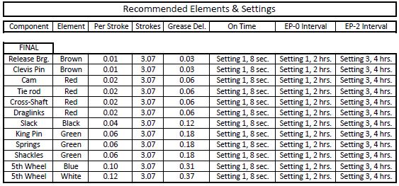
3 Grease lines If pump has been operated with an empty reservoir Are there any leaks? Fill reservoir to MAX level and operate pump continuously, (see pg.8-9) Loosen all outlet tube fittings of elements and make sure air-free lubricant emerges. Re-tighten all tube fittings. Make required repair. (Lubrication point is not being lubricated until repaired.) Are there signs of wear due to rubbing or movement? Make repairs, re-route or protect tubing to prevent further damage. Are all grease point fittings Secure? Any signs of wear? Make repairs as necessary. Lubrication / Grease points Review if any of the following is applicable to the lubrication points: - Are points too dry (no grease visible) or too wet? (Large accumulation of grease at point) All points are dry: Timer interval too long or an electrical defect. With power on check with volt-meter for voltage at pump connector. If no voltage is measured, check fuse. When the fuse is defective, replace with a 5 amp rated fuse. For timing interval adjustment, please refer to appropriate manual. All points are too wet: Timer interval too short. (See pg.10-12). Note: Check for reverse polarity as the Mk1 pump will run continuously 1 or more points are too dry/wet: - Too wet: Confirm the correct elements have been installed. Please contact Lubecore for replacement instructions. - Too dry: Confirm elements are delivering grease & the correct elements have been installed. Please contact Lubecore for replacement instructions. Some pump elements do not dispense lubricant. Test for Air Lock around suction port of the element. Unscrew element from the pump housing, and start pump cycle. After grease starts to emerge, re-install the element and re-tighten. Start another pump cycle. If the element fails to dispense lubricant again, replace the element completely. *NOTE: Depending on temperature and/or type of lubricant, it can take up to 10 minutes till the pump elements commence full delivery. 3
 MKI - Timer Board with Dipswitches for trailer application Pin 30 Red Battery (+) Pin 87 Blue (+) Motor Pin 31 Brown (-) Motor Pin 31 Brown (-) Ground Pin")
 MKI Timer Board with Dipswitches for truck application Pin 30 Red Battery (+) Pin 87 Blue (+) Motor Pin 31 Brown (-) Motor Pin 31 Brown (-) Ground Pin 15")
4 MLP/Spyder System Identification (Eg.1) MKI - Timer Board with Dipswitches for trailer application Pin 30 Red Battery (+) Pin 87 Blue (+) Motor Pin 31 Brown (-) Motor Pin 31 Brown (-) Ground Pin 15 Black Jumper Wire to Pin 30 (Eg.2) MKI Timer Board with Dipswitches for truck application Pin 30 Red Battery (+) Pin 87 Blue (+) Motor Pin 31 Brown (-) Motor Pin 31 Brown (-) Ground Pin 15 Black Ignition (+) (Eg.3) MKI Rev-A - Timer Board with Rotary Dials & Push Button Pin 15 (+) Power Black Wire Pin 31 (-) Ground Brown Wire M (+) Motor Blue Wire M (-) Motor Brown Wire Power Indicator LED Manual Test Button Cycle Indicator LED 4
5 MLP/Spyder Cycle Test Turn the ignition on if pump is mounted on a truck. If pump is mounted on a trailer, ensure the 7 way trailer plug is inserted in the nose box on the front of the trailer. Remove the magnet from its holding position located on the side of the pump and place on the marked locations on the lid of the pump as shown below. 1. Mk1 Pump requires the magnet to sit directly over the front centre lid screw with part of the magnet touching the screw. Pump should activate between 10 and 15 seconds after contact. 2. Mk2-Rev-A Pump requires the magnet be placed just left of the raised logo on the lid, between the centre screw and the mounting screw to the far left. Pump should activate between 10 and 15 seconds after contact. 1 2 The pump should cycle for the manufacture specified time. MLP/Spyder Is Not Working 1. Always remove the DIN connector from the pump and check for power and ground at the plug end. The Mk1 DIN connector has one wiring configuration while the Mk1 Rev-A has two of its own configuration. You must verify which DIN connector configuration you have, as the pump power cables are not interchangeable with each other. Example: The system you are presently working on has already had its pump changed. However the mechanic did not verify the wire harness configuration for the pump that was installed. So the pump does not work. The solution to the issue is to open the DIN connector plug and reposition the wires within the DIN connector plug so the appropriate terminal sockets in the DIN plug match up to the correct DIN pins on the receptacle base. 5
6 These are the three wiring configurations for the Mk1 & Mk1 Rev-A pumps Mk1 MLP/Spyder DIP Switches Mk1 Rev-A MLP/Spyder Dials Mk1 Rev-A2 MLP/Spyder Dials 6
7 2. On a truck - check the fuse, all connections and the DIN plug. 3. On a trailer - If a set of audible clicking is heard from the trailer the ABS has power and so should the auto-lube system. If the ABS start up sequence is not heard, you must investigate to ensure that the ABS is working before proceeding with the inspection and testing of the auto-lube system. Check ABS connection to brake module Check the ABS Y connector and the wire extension to the pump Check for corrosion at the junction box Check for corrosion at all connections including the DIN connector These items must be repaired before proceeding with the auto-lube inspection and testing, as the auto-lube system is powered by the ABS control module main harness on a trailer installed system. Cables, connections and fuse are okay but pump does not cycle. Remove the timer cover from the pump using a No.#2 Philips screw driver and verify that the timer board does not show any signs of corrosion or contamination. Mk1 - Use a multi-meter to check for power, the Red wire (pin 30) is positive (+) the Brown wire (pin 31) is (-) if power is present, attempt to cycle the pump again using the magnet. If pump does not cycle - carefully remove the Red (pin 30) (+) positive lead from the timer board and touch the Blue (pin 87)(+) wire for the motor. The motor should run and the mixing paddle should be seen moving in the reservoir. If the motor runs change the timer board, if the motor does not turn change the pump. If corrosion is found - replace timer. Mk1 Rev-A - Observe the LED referred to in (Eg.3 Pg.4) it indicates that power is present at the timer board. The Mk1 Rev-A power wire is Black (pin 15) is positive (+), the Brown wire (pin 31) is negative (-) Push the manual test button, an LED should light up just right of the Red dial, signifying that the pump is cycling according to the manufacture specifications. 7
8 If there are two LEDs lit on the timer board, but the motor is not turning. Use a piece of wire stripped at both ends and insert one end in to the back of the Molex connector behind the Blue (+) wire and the other end into the Black wire (pin 15)(+) (Eg.3 Pg.4). The motor should start running and the paddle should be seen rotating in the reservoir. If the motor runs change the timer board, if the motor does not run change the pump. MLP/Spyder Is Working But Equipment Is Dry Verify that you have power and ground at the pump DIN connector Verify time settings are correct for the installed system. Turn the ignition on if pump is mounted on a truck. If pump is mounted on a trailer, ensure the 7 way, trailer plug is inserted in the nose box on the front of the trailer and is supplying power. On the Mk1 (DIP Switch model) there is no way of causing the pump to run continually by using the magnet or the timer board. But there is an alternative way of causing the pump to run continually. Remove the Lid from the pump and using 1 pair of alligator test leads clip one end of the test lead on A which is pin 30 on the timer board or Battery and connect the other end of the test lead on B which is pin 87 on the timer board, which is motor positive. The motor will run until you remove your test leads if there is a good ground. Run the pump this way until fresh grease is visible at all grease points. B A If grease is not visible after minutes at a particular grease point, trace the secondary line back to the pump looking for leaks along the line. If no leaks are found, remove and replace the pump element with the same volumetric specifications. (Ensure that the element comes out completely intact) 8
 (pin 15) to the Blue wire")
9 On the Mk1 Rev-A pump, place the magnet over the designated area on the timer cover as shown on page 3. Leave the magnet in place and the pump will continually run until the magnet is removed. An alternative way of having the pump run continually is to insert a 3 wire, with stripped ends into the backside of the Molex connector, connecting the Black wire (+) (pin 15) to the Blue wire (Motor +). If grease is not visible after minutes at a particular grease point, trace the secondary line back to the pump looking for leaks along the line. If no leaks are found, remove and change the pump element with the same volumetric specifications. (Ensure that the element comes out completely intact) MLP/Spyder Element When removing a MLP/Spyder element from a pump for inspection, or replacement. It must come out complete, as the picture above shows. If the piston or spring is missing from the end of the element, a magnet will have to be used to retrieve the missing pieces from inside the pump housing. NOTE: Do not run the pump until the missing pieces are recovered as this will severely damage the pump!!! 9
10 MLP/Spyder Timer Settings Mk1 Time Settings 8 Position DIP Switch Settings Pause/Dwell Time (Only 1 switch can be ON pos. Except No.8) Time In Minutes No.1 No.2 No.3 No.4 No.5 No.6 No.7 No.8 ON Range OFF Range Working Time Setting (in seconds) Switch No.1 No.2 No.3 No.4 Time 10 sec. 20 sec. 40 sec. 80 sec. OFF ON Min. OFF ON Min. OFF ON Min. OFF ON Min. OFF ON Min. OFF ON Min. OFF ON Min. OFF ON Min Sec. 20 Sec. 30 Sec. 40 Sec. --- Sec. 10


11 Mk1 Rev-A Time Settings 11
12 12


13 Lubecore Service Guide Infield Repair of Loose MLP/Spyder Pump Motor Mounting Bolts LCI recently discovered a possible issue pertaining to the torque settings on the three bolts that hold the motor assembly to the MLP/Spyder pump body, this issue may result in a leaking pump and possible damage to the pump elements if not rectified. This LCC (Lube Core Communication) will guide you through an infield repair of the MLP/Spyder Pump. This repair should be able to be carried out while the MLP/Spyder pump is still mounted on the equipment in question. (NOTE: When you are looking directly at the pump, verify whether there is a serial number plate mounted on the left hand side of the green pump bracket. If there is no serial tag please contact the Lubecore International Warranty Administrator for directions on how to proceed) 5mm x 7.5mm Ball End Allen Key socket You will need a cam clamp similar to this, You will also require: 1. Inch pound torque wrench 2. Brake cleaner 3. shop rags 4. 12mm wrench 5. 14mm Deep socket 13


 and it should")
14 Firmly grasp the lid of the pump and turn either clockwise or counter clockwise depended on pump mounting location and/or space afforded to move freely. Position the cam clamp directly under the corner of the lid and activate the lever so that the cam bar causes pressure between the lid and the green bracket. Consistent pressure will cause the lid to pop off the pump. Note: Do not use anything other than a cam clamp to perform this function, otherwise you will crack the reservoir and/or lid Clean out any grease that remains in the reservoir until you can see the bottom of the reservoir. Turn the stir arm clockwise (its LH thread) and it should break loose and unthread. No tools are required to perform this. 14
 Represents the bolts that you need to tighten to 7.5 ft/lbs.")
 so you can get access to the motor mounting bolts located at the bottom of the pump.")
15 Once the grease has been removed, this is the view you will have of the inside of the MLP/Spyder pump This is a view of the inside of the pump when the reservoir is removed, DO NOT REMOVE THE RESERVOIR A A C B A A (A) Represents the bolts that you need to tighten to 7.5 ft/lbs. As you can see from the picture to the right you may have to remove a number of piston elements (B) from the pump (Pg.15-16) so you can get access to the motor mounting bolts located at the bottom of the pump. When removing these piston elements ensure they are kept in a clean location to prevent contamination which could cause premature failure of the piston element, pump or lubrication point. Slots ( C ) (Pg.15-16) located at the bottom of the reservoir will allow you access to the bolts, so you will not have to remove the reservoir from the pump body or mounting bracket to properly torque the bolts. Prior to removing the piston elements, use the 12mm wrench to release the compression nut on the lines leading to the piston element. Label these lines so you can identify which line goes to which piston element. (Colored electrical tape or masking tape and pen work) To remove the piston element slide the 14mm 12 point deep socket all the way in, until the socket is either touching the pump housing or is on the piston element body, dependant on the length of the socket. Remove piston element and store in a safe, clean location until reassembly. Insert the 5mm x 7.5mm Ball End Allen Key wrench or socket through the appropriate slot, located at the bottom of the reservoir. Lightly snug up all the bolts by hand prior to using the ft/lb torque wrench. Carefully torque the motor mounting bolts to 7.5 ft/lbs When reinserting the piston elements into the pump body ensure that all springs and piston tips are present and assembled. The springs should be holding the piston tips to the body of the element and the whole unit should be inserted as a single piece. If the springs are not holding the piston tips to the body a new piston element will be required. Reverse the procedure for re-assembly. Caution: Do Not Mix & Match Element Pins & Bodies!!!! 15


16 A light shining through the motor mounting holes show the motor mounting bolt locations with the elements in place. The yellow circle signifies the front of the pump. The Red Trapezoids show the location of the slots that can be used to access the motor mounting bolts This yellow circle signifies the front of the pump 16


17 ELEMENT HOLE 1 TOP ROW 2 MIDDLE ROW 3 BOTTOM ROW Element Removal Combination to allow access to the motor Right of front centre Back Left of front centre Torque bolts to 7.5 ft/lbs Once you have tightened up the motor mounting bolts, position the lid on top of the pump making sure that the groove in the lid matches up with the ridge of the reservoir. When you are sure that the pump lid and reservoir ridge are in line with each other. Give the lid a quick rap. The lid will then snap down onto the reservoir. Fill pump using the fill connector (DO NOT FILL THE PUMP FROM THE TOP) Test the pump. 17
18 Lubecore International 7065 Twiss Road Campbellville, ON L0P 1B0 CANADA Phone: (905) Fax: (905) Tech Assistance: Website: MLP Parts Catalogue Lubecore_PC_003_MLP rev02 18
Southwest Windpower Instruction Sheet AIR-X Circuit Replacement Kit
 Southwest Windpower Instruction Sheet AIR-X Circuit Replacement Kit Tools Required 5 / 32 Hex key 5 / 16 Hex key 7 / 64 Hex key Standard screwdriver Pair of external snap ring pliers Rubber mallet Hammer
Models CHASSIS LUBE ELECTRIC GREASE PUMP Series "C" - 13C MAY FORM Page. Section - Q3
 Models 94422 CHASSIS LUBE ELECTRIC GREASE PUMP Series "C" MAY - 2004 FORM 403467 Section - Q3 Page - 13C 9.00" (229 mm) 13.75" (350 mm) 0.35" (9mm) Mounting Holes 4.76" (121 mm) 9.84" (250 mm) Do not use
Models CHASSIS LUBE ELECTRIC GREASE PUMP Series "C" - Q3. MAY FORM Section
 Models 94822 CHASSIS LUBE ELECTRIC GREASE PUMP Series "C" - Q3 MAY - 2004 FORM 403468 Section Page - 14B 13.00" (330 mm) 17.72" (450 mm).35" (9 mm) Mounting Holes 4.72" (120 mm) 9.84" (250 mm) Figure 1
Arch HTH Water Chemicals Commercial Equipment Trouble Shooting Guide
 Arch HTH Water Chemicals Commercial Equipment Trouble Shooting Guide 8/28/00 TROUBLESHOOTER S GUIDE PROBLEM CAUSE SOLUTION Insufficient water flow to chlorinator Check water flow through Flow Controller
Detroit Speed, Inc. Electric Headlight Door Kit Corvette P/N: &
 Detroit Speed, Inc. Electric Headlight Door Kit 1968-82 Corvette P/N: 122006 & 122007 The Detroit Speed Inc. Electric Headlight Door Kit replaces the stock vacuum actuated system on all 1968-82 Corvettes.
Service Manual Air Tech Second Stage
 Service Manual Air Tech Second Stage Copyright 2002, Cressi-sub Revised 3/2002 2 Air Tech Second Stage Service Manual Contents BEFORE STARTING... 3 DISASSEMBLY... 3 PARTS CLEANING AND LUBRICATION... 9
VECTRIX VX-2 SERVICE MANUAL. Version 1.0/May 2011 VECTRIX, LLC
 www.vectrix.com CONTENTS SECTION A: Tools 1 Tools Needed SECTION B: Mechanical Parts 1 Front Fairing 2 Front Console Cover 3 Speedometer Cover 4 Front Vertical Panel Cover-Lower 5 Front Vertical Panel
Power Steering Pump. GM Century/Lumina/Grand Prix/Intrigue REMOVAL & INSTALLATION BLEEDING
 1 of 9 GM Century/Lumina/Grand Prix/Intrigue 1997-2000 Power Steering Pump REMOVAL & INSTALLATION BLEEDING When servicing the power steering pump, inspect the power steering fluid. Look for foaming, milky
Prerequisites: Shop Manual (recommended) pages 3-9 through 3-13.
 pages 3-9 through 3-13.") Prerequisites: Order your gaskets average about $25.00 bucks X 2 so $50.00 4NK-11193-00-00 Obtain a shim kit (Should have several 265 and 270s) (Some dealers will exchange) Obtain a Valve Bucket Tool YM-33961
Prerequisites: Order your gaskets average about $25.00 bucks X 2 so $50.00 4NK-11193-00-00 Obtain a shim kit (Should have several 265 and 270s) (Some dealers will exchange) Obtain a Valve Bucket Tool YM-33961
THIS GUIDE IS INTENDED FOR DEALERS AND SOLAR COMFORT TECHNICIANS ONLY AND IS NOT MEANT OR INTENDED TO BE REPRODUCED OR DISTRIBUTED TO THE CONSUMER
 THIS GUIDE IS INTENDED FOR DEALERS AND SOLAR COMFORT TECHNICIANS ONLY AND IS NOT MEANT OR INTENDED TO BE REPRODUCED OR DISTRIBUTED TO THE CONSUMER Table of Contents Page Tools Needed (A) 3 Replacement
Model CHASSIS LUBE ELECTRIC GREASE PUMP Series "C"
 Model 94222 CHASSIS LUBE ELECTRIC GREASE PUMP Series "C" Indicates change MAY - 2004 FORM 403466 Section - Q3 Page - 12B 7.75" (197 mm) 12.6" (321 mm) 0.35" (9 mm) Mounting Holes 4.85" (123 mm) 8.85" (225
08-18 STI Flex Fuel Bluetooth Mk2 Kit Install Instructions For Cobb Tuning Access Port
 For Cobb Tuning Access Port Delicious Tuning 1948 Don Lee Place Suite #7 Escondido, CA 92029 408-480-0995 Rough Draft BJP Rev: 2.0 Date: 2/1/17 FFBT parts: (1) Ethanol Content Analyzer Module (1) Ethanol
INSTALLATION INSTRUCTIONS
 INSTALLATION INSTRUCTIONS REAR DISC CONVERSION KIT A126-2 1988-98 C1500 2WD 10" REAR DRUM Thank you for choosing STAINLESS STEEL BRAKES CORPORATION for your braking needs. Pleases take the time to read
2003 Saturn Vue. SATURN 3.0L V6 DOHC - L-Series After VIN & Vue
 TIMING BELT Removal 1. Disconnect negative battery cable. Remove air cleaner assembly. 2. Raise and support vehicle. Remove right front wheel. Remove lower front splash shield. 3. Lower vehicle. Loosen,
TOYOTA TUNDRA HANDS FREE BLU LOGIC Preparation
 TOYOTA TUNDRA 2008- HANDS FREE BLU LOGIC Preparation Part #: PT923-00111 Conflicts: JBL Audio NOTE: Part number of this accessory may not be the same as the part number shown. Kit Contents: For kits manufactured
or OWNER S MANUAL MODEL R
 www.superiorwaterandair.com 801-974-9090 or 800-974-7638 OWNER S MANUAL MODEL 48-1000R Table of Contents Introduction...Page 1 Flow Diagrams...Page 3 The Electro-mechanical Timer Programming...Page 4 Extra
P-600. Technical Manual. Troubleshooting Repairs Replacements
 P-600 Technical Manual Troubleshooting Repairs Replacements Table of Contents P-600 Lift Symptoms and Problems Finding the Problem Before Getting Inside 3 Pneumatic Systems 4 Electrical Systems 5 Mechanical
Service Manual Air Plus Second Stage
 Service Manual Air Plus Second Stage Includes XS Series Second Stage Copyright 2002, Cressi-sub Revised 3/2002 2 Air Plus Second Stage Service Manual Contents BEFORE STARTING... 3 DISASSEMBLY... 3 PARTS
INSTALLATION INSTRUCTIONS for HI-1 and HI-2 MOTORCYCLE IGNITIONS. Part Numbers and INTRODUCTION COIL AND SPARK PLUG CABLE CONSIDERATIONS
 INSTALLATION INSTRUCTIONS for HI- and HI- MOTORCYCLE S Part Numbers 8-000 and 8-000 CAUTION: READ INSTRUCTIONS CAREFULLY BEFORE STARTING INSTALLATION INTRODUCTION Crane HI- and HI- ignition systems are
SPECIFICATIONS CONTENTS: Warning Information. Operating Instructions Preventative Maintenance and Troubleshooting
 Model 3322 22 Ton Air/Hydraulic Truck Axle Jack OWNER'S MANUAL CONTENTS: Page 1 Page 2 Page 3-4 Page 4-5 Page 5 Page 6 Page 7 Page 8 Specifications Warning Information Assembly Operating Instructions Preventative
Flex Fuel Bluetooth Kit WRX install instructions
 Delicious Tuning 1948 Don Lee Place Suite #7 Escondido, CA 92029 408-480-0995 BJP Rev: 1.0 Date: 10/1/15 FFBT parts: (1) Ethanol Content Analyzer Module (1) Ethanol Content Analyzer Sensor (1) Sensor Bracket
Firehawk Responder Second Stage Regulator
 Firehawk Responder Second Stage Regulator MAINTENANCE AND REPAIR MSA 511 (L) Rev. 4 MSA 2015 Prnt. Spec. 10000005389(I) Mat. 10096394 Doc. 10096394 Replacement Kits and Overhaul Kit P/N Description Firehawk
CAUTION: READ INSTRUCTIONS CAREFULLY BEFORE STARTING INSTALLATION
 V-Twin MFG. VT No. 32-9500 V-TECH 1 IGNITION KIT, SINGLE FIRE FITS EV SHOVEL, XL THRU 1997 VT No. 32-9503 V-TECH 1 IGNITION KIT, SINGLE FIRE FITS EV, SHOVEL, XL, WITH COIL AND WIRES This is a custom application
Conflicts: Vehicles without a sunroof Vehicles with a single sunroof
 Toyota Sienna (Dual Sunroof) 2011-10.2 Overhead Video Part Number: 00016-00110 00016-00110-17 Fit Kit 00016-00120 00016-00120-17 Fit Kit Accessory Code: ED5 Conflicts: Vehicles without a sunroof Vehicles
M52tu-M54 VANOS Assembly & Timing Using G.A.S. Professional Cam Tool Kit
 Home BMW Solutions Porsche Solutions DIY Tech Engine Services Dyno Services Machining About Contact Store Tool Rental M52tu-M54 VANOS Assembly & Timing Using G.A.S. Professional Cam Tool Kit This procedure
WORK INSTRUCTION READ FIRST. IF IN DOUBT
 WORK INSTRUCTION PAGE 1 OF 9 FIELD CHANGE INSTRUCTION : TO CHANGE A BACK DOOR AND SIDE LIFT PROCEDURE: Step 1. How to remove and replace the rear door of a canopy. Step 2. How to remove the side lift up
Installation Manual TWM Performance Short Shifter Cobalt SS/SC, SS/TC, HHR SS, Ion Redline and Saab 9-3
 Page 1 Installation Manual TWM Performance Short Shifter Cobalt SS/SC, SS/TC, HHR SS, Ion Redline and Saab 9-3 Please Note: It is preferable to park on a flat surface, as you will have to engage and disengage
Mustang One-Touch Convertible Top Module (2005+) - Installation Instructions
 - Installation Instructions") Mustang One-Touch Convertible Top Module (2005+) - Installation Instructions The below installation instructions work for the following products: Mustang One-Touch Convertible Top Module (2005+) Please
Mustang One-Touch Convertible Top Module (2005+) - Installation Instructions The below installation instructions work for the following products: Mustang One-Touch Convertible Top Module (2005+) Please
Installation Manual v1.0: Twin CP3 Fuel Injection Kit Dodge 6.7L
 04/05/2012 Dodge 2010-2011 6.7L Twin CP3 701-900-2356-INST Installation Manual v1.0: Twin CP3 Fuel Injection Kit 2010-2011 Dodge 6.7L Figure 1 - Full Kit Photo 29 Figure 2 - Hardware Kit (800) 949-60002
DrVanos.com Stage II Installation Instructions. Tool rental is available with the purchase of a vanos kit *See website for more info*
 DrVanos.com Stage II Installation Instructions Special Tools Needed: Camshaft locking tool TDC Crank pin Sprocket turning tool Tool rental is available with the purchase of a vanos kit *See website for
HYDRAULICS. TX420 & & lower. Hydraulic Tandem Pump Removal. 4. Remove the LH side panel (Fig. 0388).
.") TX420 & 425 240000299 & lower 4. Remove the LH side panel (Fig. 0388). Hydraulic Tandem Pump Removal Note: Cleanliness is a key factor in a successful repair of any hydraulic system. Thoroughly clean all
TX420 & 425 240000299 & lower 4. Remove the LH side panel (Fig. 0388). Hydraulic Tandem Pump Removal Note: Cleanliness is a key factor in a successful repair of any hydraulic system. Thoroughly clean all
Conflicts: JBL Audio, Factory Navigation, Accessory XM Satellite Radio, and Accessory Sirius Satellite Radio
 TOYOTA YARIS SEDAN 2008- HANDS FREE BLU LOGIC Preparation Part #: PT923-00111 NOTE: Part number of this accessory may not be the same as the part number shown. Conflicts: JBL Audio, Factory Navigation,
INSTALLATION INSTRUCTIONS
 INSTALLATION INSTRUCTIONS REAR DISC BRAKE CONVERSION KITS A112, A112-1 & A112-93 1979-93 FORD MUSTANG with 7.5" & 8.8" AXLES Thank you for choosing STAINLESS STEEL BRAKES CORPORATION for your braking needs.
Installation Manual TWM Performance Short Shifter Subaru STi 2008+
 - 1 - Installation Manual TWM Performance Short Shifter Subaru STi 2008+ Please Note: It is preferable to park on a flat surface, as you will have to engage and disengage the hand brake and shift from
TOYOTA VENZA HANDS FREE BLU LOGIC Preparation
 TOYOTA VENZA 2009- HANDS FREE BLU LOGIC Preparation Part #: PT923-00111 Conflicts: JBL Audio NOTE: Part number of this accessory may not be the same as the part number shown. Kit Contents: For kits manufactured
SCION xa AUTO-DIMMING MIRROR Preparation
 Preparation Part Number: PT374-52040 (Compass) PT374-21050 (Homelink) Kit Contents Item # Quantity Reqd. Description 1a 1 AD Mirror Assembly w/compass & Map Lights (P/N PT374-52040) 1b 1 AD Mirror Assembly
LEAK TEST PROCEDURE APPLICABLE TO DC3 INTELLI-GRIP LIFTERS MODELS MRT4-DC3, MRTA8-DC3, MRTALP8-DC3 AND PC/P1-DC3 SERIES
 LEAK TEST PROCEDURE APPLICABLE TO DC3 INTELLI-GRIP LIFTERS MODELS MRT4-DC3, MRTA8-DC3, MRTALP8-DC3 AND PC/P1-DC3 SERIES TESTING AND MAINTENANCE MUST BE DONE BY A QUALIFIED PERSON KEEP FOR FUTURE REFERENCE
Installation Instructions COMPETITION/PLUS SHIFTER Ford Mustang MT82 6-Speed Manual Transmission Catalog#
 Installation Instructions COMPETITION/PLUS SHIFTER 2015-2017 Ford Mustang MT82 6-Speed Manual Transmission Catalog# 3916037 Rev. 00 WORK SAFELY! For maximum safety, perform this installation on a clean,
INSTALLATION INSTRUCTIONS
 INSTALLATION INSTRUCTIONS REAR DISC BRAKE CONVERSION KIT A126-3 1988-98 CHEVY K1500 4WD 10" DRUMS Thank you for choosing STAINLESS STEEL BRAKES CORPORATION for your braking needs. Pleases take the time
Second Stage Regulator - 1/4 Turn
 Second Stage Regulator - 1/4 Turn MAINTENANCE AND REPAIR TAL 806 (L) Rev. 6 MSA 2008 Prnt. Spec. 10000005389 (I) Mat. 10042827 Doc. 10000015245 1/4 TURN SECOND STAGE REGULATOR SECOND STAGE REGULATOR COMPONENTS
TOYOTA CAMRY HANDS FREE BLU LOGIC Preparation
 TOYOTA CAMRY 2008- HANDS FREE BLU LOGIC Preparation Part #: PT923-00111 Conflicts: JBL Audio, Factory Navigation NOTE: Part number of this accessory may not be the same as the part number shown. Kit Contents:
SD Bendix E-10PR Retarder Control Brake Valve DESCRIPTION. OPERATION - Refer to Figure 2
 SD-03-832 Bendix E-10PR Retarder Control Brake Valve MOUNTING PLATE SUPPLY 4 PORTS ELECTRICAL AUXILIARY DESCRIPTION TREADLE RETARDER CONTROL SECTION EXHAUST DELIVERY 4 PORTS FIGURE 1 - E-10PR RETARDER
TOYOTA SIENNA TRAILER WIRE HARNESS Preparation
 Preparation Part Number: PT791-08150 (non-se) PT791-08102 (SE only) Kit Contents Item # Quantity Reqd. Description 1 1 Trailer Module Harness 2 1 4-Flat Harness 3 1 Battery Power Wire Harness 4 1 Mounting
Detroit Speed, Inc. Electric Headlight Door Kit Corvette P/N: &
 Detroit Speed, Inc. Electric Headlight Door Kit 1968-82 Corvette P/N: 122006 & 122007 The Detroit Speed Inc. Electric Headlight Door Kit replaces the stock vacuum actuated system on all 1968-82 Corvettes.
Peristaltic Pump Operating Instructions
 Peristaltic Pump Operating Model 410 IMPORTANT Pump is water resistant but not waterproof. Do not submerge in water. Pumping rates will decrease as the amount of lift increases. Remove tubing when stored.
Installation Instructions
 Instructions Aerada 900 Series Futura Faucet With Battery (BIR) Infrared Control S53-284 4" Centerset/Centershank S53-289 Centerset/Centershank w/plate Table of Contents Pre- Information............2 900
Firehawk Second Stage Regulator Fire Service
 Firehawk Second Stage Regulator Fire Service MAINTENANCE AND REPAIR TAL 1701 (L) Rev. 2 MSA 2017 Prnt. Spec. 10000005389(I) Mat. 10147454 Doc. 10147454 TAL 1701 (L) Rev. 2-10147454 2 NON-CBRN FIREHAWK
SCION TC HANDS FREE BLU LOGIC Preparation
 SCION TC 2008- HANDS FREE BLU LOGIC Preparation Part #: PT923-00099 Conflicts: JBL Audio NOTE: Part number of this accessory may not be the same as the part number shown. Kit Contents: For kits manufactured
Depress each tab as you pull the bezel off. The bezels are tight. L.H. shown.
 2013-2014 Ford Mustang V6 & Boss 302 Lower Valance Fog Light Kit Parts List: Quantity: Tool List: Fog light & bulb with bracket 2 Flat head & Phillips screwdriver Black bezels 2 Ratchet & Socket set OR
Installation Manual. Model T680A/B Engine Brakes. For Mack 6 Cylinder, 4 Valve Head E6 and E7 Series Engines. Engine Brakes
 Engine Brakes Installation Manual Model T680A/B Engine Brakes For Mack 6 Cylinder, 4 Valve Head E6 and E7 Series Engines TecBrake P.O. Box 27822 Houston, Texas 77227 INSTALLATION MANUAL TECBRAKE T680A
Headlight Removal & Installation: VW Jetta Mk.4 / Bora
 Headlight Removal & Installation: 99-04 VW Jetta Mk.4 / Bora Disclaimer: Buyer assumes any and all risk and liability from the installation and use of this product. Seller, author, or any of their affiliates
General Applicability Note: Recommended Tools. Personal & Vehicle Protection Safety Goggles Seat Covers Floor Covers Special Tools. Installation Tools
 TOYOTA HIGHLANDER/HIGHLANDER HV 2008- Preparation Part #: PT923-00111 Conflicts: JBL Audio, Factory Navigation NOTE: Part number of this accessory may not be the same as the part number shown. Kit Contents:
 Special Tools Needed: DrVanos.com Stage I Installation Instructions Camshaft locking tool TDC Crank pin Sprocket turning tool Tool rental is available with the purchase of a vanos kit *See website for
SERVICE INSTRUCTIONS FOR SEAL REPLACEMENT OF POWER GEAR HYDRAULIC LEVELING LEGS
 SERVICE INSTRUCTIONS FOR SEAL REPLACEMENT OF POWER GEAR HYDRAULIC LEVELING LEGS 82-L0352 REV 8 4-27-2011 WARNING! HYDRAULIC COMPONENTS CAN CAUSE SERIOUS INJURY OR DEATH IF PROPER SAFETY PRECAUTIONS ARE
6500DC Dual Motor Wireless Controller Kits
 6500DC Dual Motor Wireless Controller Kits READ ALL DIRECTIONS FIRST BEFORE PROCEEDING NOTE: SEE THE QUICK PROGRAM INSTRUCTIONS BEFORE OPERATING THE FIRST TIME. DO NOT REMOVE THE TRANSMITTER BATTERY Please
OPERATORS MANUAL/INSTRUCTIONS/PARTS & SERVICE FOR MANUAL & ELECTRIC
 OPERATORS MANUAL/INSTRUCTIONS/PARTS & SERVICE FOR MANUAL & ELECTRIC TABLE OF CONTENTS SAFETY DELIVERY INSPECTION OPERATION 4 MAINTENANCE 5 TROUBLE SHOOTING 5 PARTS 6-15 Frame Scissor Assembly 6-7 Thrust
ELECTRICAL SYSTEM UPGRADE
 NEW CONTROLLER & ELECTRICAL SYSTEM UPGRADE FOR DAIRY TECH, INCORPORATED 10, 30 & 60G PASTEURIZERS Parts to Include 2 Wire ties (Nuts) 2 sticky wire mount pads Large Rubber Grommet (for bottom of electric
D-15/G-15 Maintenance
 D-15/G-15 Maintenance NOTE: The numbers in parentheses are the Reference Numbers on the exploded view illustrations found later in this manual and in the Parts Manual. Daily Check the oil level and the
SD Bendix ET-2 Electronic Treadle DESCRIPTION OPERATION
 SD-15-4106 Bendix ET-2 Electronic Treadle PIVOT SPRING MOUNTING BASE DESCRIPTION CONNECTOR FIGURE 1 - ET-2 ELECTRONIC TREADLE ROLLER TREADLE COVER DOUBLE RETURN SPRING CABLE ASSEMBLY The ET-2 is an electronic
INSTALLATION INSTRUCTIONS for HI-4 DUAL FIRE MOTORCYCLE IGNITION. Part Number INTRODUCTION REMOVAL OF POINTS IGNITION TO 1977 MODELS
 INSTALLATION INSTRUCTIONS for HI- DUAL FIRE MOTORCYCLE IGNITION Part Number -00 CAUTION: READ INSTRUCTIONS CAREFULLY BEFORE STARTING INSTALLATION INTRODUCTION The HI- ignition system is intended for use
Discount-Equipment.com
 REQUIRED TOOLS LS Series Remix Shaft Installation Instructions /8", /6", /2" Allen Wrenches Snap Ring Pliers (Light Duty) /" Combination Wrench Loctite #22 Blue /" Socket w/ /8" Ratchet Electric Drill
VW/AUDI MK7 VEHICLES
 Installation Manual P/N 1-301-1708-01 (STAGE 2+ FUEL KIT) P/N 1-301-1708-02 (STAGE 3+ FUEL KIT) VW/AUDI MK7 VEHICLES Warning: This installation is not recommended for a novice or the new guy in the shop.
Ignition Lock Cylinder
 1998 Cadillac Deville 6L SFI DOHC 8cyl 1 of 7 9/7/2010 7:41 PM GM Cadillac Deville_Fleetwood_ELD_Seville 1990-1998 Ignition Lock Cylinder REMOVAL & INSTALLATION CAUTION When performing service around Supplemental
Audi-Larm TM Audible Alarm: AirHawk II Air Mask
 Audi-Larm TM Audible Alarm: AirHawk II Air Mask MAINTENANCE AND REPAIR MSA 011 (L) Rev. 0 MSA 2010 Prnt. Spec. 10000005389(I) Mat. 10104323 Doc. 10104323 REPLACEMENT KITS AND PARTS LIST Item P/N Description
HEAVY DUTY TROLLEY JACK. Operation Manual
 HEAVY DUTY TROLLEY JACK 4T Operation Manual Make sure to read and fully understand the instruction manual before using this product and keep the manual properly 1 General Description Product Description
Disassembly and Reassembly for CBB (Double Acting) Series Pneumatic Actuators
 Series Pneumatic Actuators") MECATORK S.A.S Release: May 2012 Disassembly and Reassembly for CBB (Double Acting) Series Pneumatic Actuators MECATORK S.A.S Table of Contents May 2012 Table of Contents Section 1: Introduction 1.1 General
MECATORK S.A.S Release: May 2012 Disassembly and Reassembly for CBB (Double Acting) Series Pneumatic Actuators MECATORK S.A.S Table of Contents May 2012 Table of Contents Section 1: Introduction 1.1 General
ADM Performance 6079 Mapleshade Lane Dallas, Texas (214)
") 1) Disconnect Battery Ground 2) Raise front end of Vehicle FAN INSTALL INSTRUCTIONS 3) Remove lower Radiator hose and drain coolant into a pan. (you will reuse coolant later) 4) Remove Air Intake piping
1) Disconnect Battery Ground 2) Raise front end of Vehicle FAN INSTALL INSTRUCTIONS 3) Remove lower Radiator hose and drain coolant into a pan. (you will reuse coolant later) 4) Remove Air Intake piping
Product Features. Easy installation. Pump adds only 3.3 to the overall assembly height. 60 GPH (227 LPH) flow rate while in priming mode.
 flow rate while in priming mode.") Primer Pump Kits RKP1912 (12 vdc) and RKP1924 (24 vdc) Instruction Part Number 14356 Rev C Primer pump kits are an innovative and proprietary system consisting of a prescreen filter, a flow by-pass circuit,
Primer Pump Kits RKP1912 (12 vdc) and RKP1924 (24 vdc) Instruction Part Number 14356 Rev C Primer pump kits are an innovative and proprietary system consisting of a prescreen filter, a flow by-pass circuit,
72 Mustang Mach 1 tachometer cluster and gauge conversion
 72 Mustang Mach 1 tachometer cluster and gauge conversion Dated: 02-17-2009 (drafted by a Chevy person working on his first Ford -not good-) Revised: 11-05-2010 The following information pertains to how
GPS AutoSteer System Installation Manual
 GPS AutoSteer System Installation Manual Supported Vehicles Case IH Vehicles Case 2577 Combines Case 2588 Combines Accuguide Ready PN: 602-0233-01-A LEGAL DISCLAIMER Note: Read and follow ALL instructions
COMPONENT WORK SAMPLE 8 Simulated Assembly MAINTENANCE MANUAL. From 1974 to March 15, 2003
 COMPONENT WORK SAMPLE 8 Simulated Assembly MAINTENANCE MANUAL From 1974 to March 15, 2003 Copyright 2008 VALPAR International Corporation P.O. Box 5767 Tucson, Arizona 85703-5767 All rights reserved. No
Push Start Ignition (05-10 All) Installation
 Installation") Tools Required: Phillips head screwdriver Flat head screwdriver Ratchet 7mm Socket Torx T20 bit Wire strippers/cutters Hand file Needle nose pliers Installation Instructions: Push Start Ignition (05-10
Tools Required: Phillips head screwdriver Flat head screwdriver Ratchet 7mm Socket Torx T20 bit Wire strippers/cutters Hand file Needle nose pliers Installation Instructions: Push Start Ignition (05-10
Z-Truck (Vertical Moving) Z-truck Flag. Y-Truck (Horizontal Moving) FIGURE 1: VIEW OF THE Z-TRUCK. Flexshaft Assembly
 Z-truck Flag. Y-Truck (Horizontal Moving) FIGURE 1: VIEW OF THE Z-TRUCK. Flexshaft Assembly") Checking and Replacing the AC Motor To remove and replace the AC Motor you will need the following tools: #2 Phillips screwdriver (magnetic tip preferred) Removing the AC Motor 1. Ready the machine by
Checking and Replacing the AC Motor To remove and replace the AC Motor you will need the following tools: #2 Phillips screwdriver (magnetic tip preferred) Removing the AC Motor 1. Ready the machine by
D40C HINGE # x Support Plate x M8 Bolt 8 x M8 Washer 6 x M6 20mm Bolts 6 x M6 Washers 19 x Screws
 HINGE # 1017 2 x Support Plate 1018 8 x M8 Bolt 8 x M8 Washer 6 x M6 20mm Bolts 6 x M6 Washers 19 x Screws 2 x Lid mount gas strut bracket 1041 2 x Self tap strut mount 1040 1 x Central Lock bracket 1510
Training Documentation
 Training Documentation Manual Shades There are two styles of adjustment wheels for Manual Shades: External Adjuster No tools needed. Wheel is turned by hand. Slot Adjuster (Accessed thru bracket end) Flat
Toyota 4Runner Oil Change (4.7L V8)
") 2003-2009 Toyota 4Runner Oil Change (4.7L V8) Change the oil in your 2003-2009 Toyota 4Runner, with 4.7L V8 engine, to improve engine performance and longevity. Written By: Ryan Bailey ifixit CC BY-NC-SA
2003-2009 Toyota 4Runner Oil Change (4.7L V8) Change the oil in your 2003-2009 Toyota 4Runner, with 4.7L V8 engine, to improve engine performance and longevity. Written By: Ryan Bailey ifixit CC BY-NC-SA
COMPONENT WORK SAMPLE 14 Integrated Peer Performance MAINTENANCE MANUAL
 COMPONENT WORK SAMPLE 14 Integrated Peer Performance MAINTENANCE MANUAL Copyright 2003 VALPAR International Corporation P.O. Box 5767 Tucson, Arizona 85703-5767 All rights reserved. No part of this manual
Tooling Assistance Center
 Safeguards are designed into this application equipment to protect operators and maintenance personnel from most hazards during equipment operation. However, certain safety precautions must be taken by
TOYOTA tc HANDS FREE BLU LOGIC Preparation
 TOYOTA tc 2011- HANDS FREE BLU LOGIC Preparation Part #: PT923-00111 Conflicts: JBL Audio, Factory Navigation NOTE: Part number of this accessory may not be the same as the part number shown. Kit Contents:
MOTOALLIANCE WINCH MOUNT
 , / 1-866-527-7637 www.motoalliance.com MOTOALLIANCE WINCH MOUNT Polaris RZR Thank you for purchasing our MotoAlliance winch mount(s). You now own a premium custom winch mount to allow you to use your
Ford Mustang V6 OEM-Style Fog Light Kit Parts List: Quantity: Tool List:
 2015-2017 Ford Mustang V6 OEM-Style Fog Light Kit Parts List: Quantity: Tool List: LED Foglights/ Bezels 2 Flat head & Phillips screwdriver (if you ordered part#3600) Ratchet & Socket set OR Wiring harness
SCION tc SECURITY (V5) Preparation
 Preparation") Preparation Part Number: PT398-21070 Kit Contents Item # Quantity Reqd. Description 1 1 2 1 GBS ECU Hardware Bag Contents Item # Quantity Reqd. Description 1 1 V5 Security ECU 2 1 ECU Mounting Bracket
Preparation Part Number: PT398-21070 Kit Contents Item # Quantity Reqd. Description 1 1 2 1 GBS ECU Hardware Bag Contents Item # Quantity Reqd. Description 1 1 V5 Security ECU 2 1 ECU Mounting Bracket
Meritor WABCO Antilock Braking System (ABS) 42.06
 42.06") Meritor WABCO Antilock Braking System (ABS) 4.06 Control Valve Replacement Replacement NOTE: Wire repairs may require the use of special tools for certain connectors and terminals. See Group 54 for information
Meritor WABCO Antilock Braking System (ABS) 4.06 Control Valve Replacement Replacement NOTE: Wire repairs may require the use of special tools for certain connectors and terminals. See Group 54 for information
Operation and Maintenance Manual for BS and BH Hydraulic Torque Wrenches
 BOLTORQ Operation and Maintenance Manual for BS and BH Hydraulic Torque Wrenches It is operating manual of BS series and BH series wrenches, please read carefully and follow the instructions. Warning and
ACCEL Distributor Model #A557
 FORM 1627 REV1 INSTALLATION INSTRUCTIONS ACCEL Distributor Model #A557 CAUTION: CAREFULLY READ INSTRUCTIONS BEFORE PROCEEDING. NOT LEGAL FOR USE OR SALE ON POLLUTION CONTROLLED VECHICLES OVERVIEW ACCEL
Steeda S550 MT-82 Tri-Ax Race Short Throw Shifter Installation Instructions For Parts: ,
 Steeda S550 MT-82 Tri-Ax Race Short Throw Shifter Installation Instructions For Parts: 555-7317, 555-7318 Tools required 1. 7mm socket 2. 10mm socket 3. 13mm socket 4. 15mm socket 5. 18mm socket 6. 3/8
Installation Manual TWM Performance Short Shift Kit Stage 1 and Stage 2 MazdaSpeed 6
 Page 1 Installation Manual TWM Performance Short Shift Kit Stage 1 and Stage 2 MazdaSpeed 6 Please Note: It is preferable to park on a flat surface, as you will have to engage and disengage the hand brake
OIL FIELD ELECTRIC ACTUATOR INSTRUCTION MANUAL SPECIAL APPLICATIONS ACTUATORS Q 6.0.1
 OIL FIELD ELECTRIC ACTUATOR INSTRUCTION MANUAL SPECIAL APPLICATIONS ACTUATORS Q 6.0.1 This instruction manual contains important information regarding the installation, operation, and troubleshooting of
Tru-Billet Climate Control Knob Installation Instructions
 P/N S197-525-07 2007-08 Tru-Billet Climate Control Knob Installation Instructions Thank you for your purchase of SilverHorse Racing products. Please read all directions before beginning the installation.
Brake Fluid Exchange
 Brake Fluid Exchange OJT / Practice DTOG Proficiency Exam Date: Trainee: Trainer: Service Center: Brake Fluid Exchange 1. Prepare for service Wear proper Personal Protective Equipment Recommended PPE:
Primus Wind Power. AIR Circuit Replacement Instructions
 Primus Wind Power AIR Circuit Replacement Instructions Items included with this kit: (see Exploded View p. 3) ITEM ITEM NAME QUANTITY 1 SCREW - SOCKET HEAD - 10-24 X 1-1/2" 4 includes 1 spare 2 O-RING
INSTALLATION INSTRUCTIONS
 INSTALLATION INSTRUCTIONS Models: 7105 & 7105TK Dodge Ram 1500 ('02 Current) Ram 2500 & 3500 '03 - Current with stock manual mirrors. IF YOU DO NOT CURRENTLY HAVE MANUAL MIRRORS, THE WRONG SET HAS BEEN
Rineer 15 Series Hydraulic Motor Service Manual
 Section 4-2 Rineer 15 Series Hydraulic Motor Service Manual Removal of 15 Series Shaft Seal Step 1 Remove snap ring. See Figure 1. WARNING: Use caution when removing snap ring. If released accidentally,
LEAK TEST PROCEDURE MRT4-DC LIFTERS SINGLE VACUUM SYSTEMS TESTING AND MAINTENANCE MUST BE DONE BY A QUALIFIED PERSON KEEP FOR FUTURE REFERENCE
 LEAK TEST PROCEDURE MRT4-DC LIFTERS SINGLE VACUUM SYSTEMS TESTING AND MAINTENANCE MUST BE DONE BY A QUALIFIED PERSON KEEP FOR FUTURE REFERENCE TST-011 Rev. 2013-049 Page 1 of 12 THIS PAGE INTENTIONALLY
LEAK TEST PROCEDURE MRTALPCH611LDC REMOTE READY LIFTERS W/ 3 BUTTON CONTROL APPLICABLE TO LIFTERS WITH SERIAL NUMBERS GREATER THAN #
 LEAK TEST PROCEDURE MRTALPCH611LDC REMOTE READY LIFTERS W/ 3 BUTTON CONTROL APPLICABLE TO LIFTERS WITH SERIAL NUMBERS GREATER THAN # 20100742 TESTING AND MAINTENANCE MUST BE DONE BY A QUALIFIED PERSON
SPECIFICATIONS CONTENTS: Specifications Warning Information. Operating Instructions Preventative Maintenance and Troubleshooting
 Model 3322 22 Ton Air/Hydraulic Truck Axle Jack OWNER'S MANUAL CONTENTS: Page 1 Page 2 Page 3-4 Page 4-5 Page 5 Page 6 Page 7 Page 8 Specifications Warning Information Assembly Operating Instructions Preventative
* * APPLICABLE MODELS: 2014 > Mazda 3
 PART NUMBER: 0000 8C L48 (DIO) / 0000 89 L84 (PIO) GENUINE ACCESSORIES INSTALLATION INSTRUCTIONS Rev. AAA *550-0700-000* APPLICABLE MODELS: 2014 > Mazda 3 REQUIRED COMPONENTS: ITEM QTY DESCRIPTION Usage
CERTAIN TRANSIT VEHICLES EQUIPPED WITH A TRAILER MODULE TRAILER MODULE FUSE AND FOOTWELL DRAINAGE HOLE
 PAGE 1 OF 19 CERTAIN 2015-2017 TRANSIT VEHICLES EQUIPPED WITH A TRAILER MODULE TRAILER MODULE FUSE AND FOOTWELL DRAINAGE HOLE OVERVIEW In the affected vehicles, it may be possible for water to pool and
Kysor On/Off Rear Air Fan Drive
 . Proper precautions must be taken to prevent personal injury from contact with moving parts, unintended engine start, or other hazards present when working with powered equipment. Refer to the vehicle
TOYOTA RAV TRAILER WIRE HARNESS Preparation
 Preparation Part Number: PU322-42013-UW Kit Contents Item # Qty Description 1 1 Trailer Module Harness 2 1 Trailer 4-Flat Harness 3 1 Trailer Power Wire Harness 4 1 Mounting Bracket, 4-Flat 5 2 Screw #10-24