MOTOALLIANCE WINCH MOUNT
|
|
|
- Amice Lane
- 6 years ago
- Views:
Transcription

1 , / MOTOALLIANCE WINCH MOUNT Polaris RZR Thank you for purchasing our MotoAlliance winch mount(s). You now own a premium custom winch mount to allow you to use your winch with your UTV / SxS. Please note the following instructions and heed all warnings. Please use common sense when operating your UTV / SxS. Read your Winch Operator s Manual and all other Operator Manual s, including warning labels, before operating your UTV / SxS. Be observant of moving parts causing entanglement, use extreme caution! SEVERE INJURY OR DEATH MAY RESULT IF YOU ARE NEGLIGENT @motoalliance.com
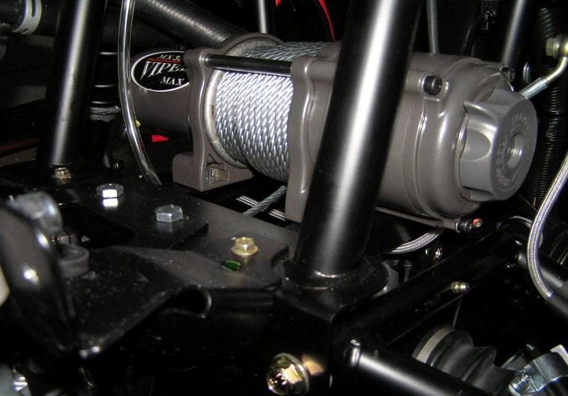
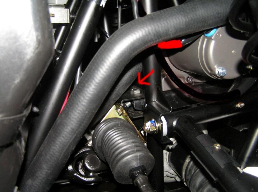
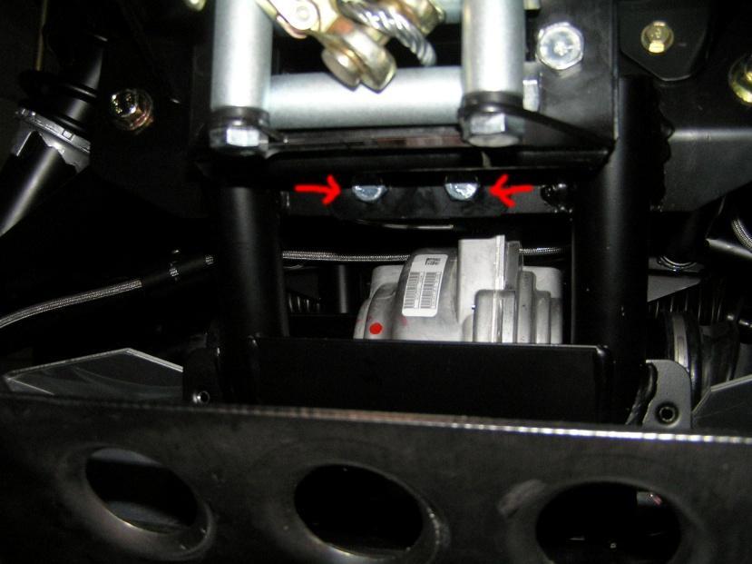
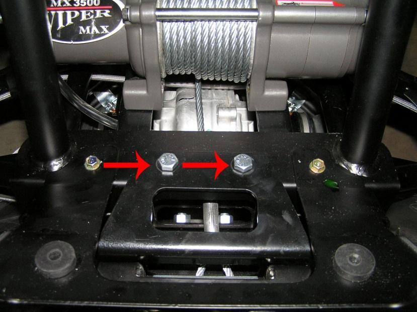
2 Please verify that all hardware and parts are included in your package. Kit Content: Mount Plates (3) 3/8-16 x ¾ cap screws (10) 3/8 flat washers (10) 3/8 nylock nuts (10) Installation Preparation: 1. Remove the driver seat and disconnect the negative (black) wire using a 10mm wrench. 2. Remove the positive (red) wire. 3. Remove all hardware from your winch and from the RZR kit. Winch Installation: 1. Install winch mounts first. Locate in chassis and fasten with four 3/8-16 x 3/4 cap screws and four lock washers. Tighten firmly. It is best to use a torque wrench to 18ft/lbs. 2. Install the winch to the winch mounts using four 5/16 bolts and four lock washers as included with your winch. Torque to 12ft/lbs. 3. Install the fairlead bracket. Remove the winch cover panel in the front bumper by removing the four 25 torx screws. Install the fairlead bracket to the chassis and then the fairlead to the bracket with 3/8-16 x ¾ cap screws. 4. Ensure the winch is orientated so the cable comes off from the bottom side of the spool. Tighten assembly after all cap screws are installed. 5. Route the cable through the fairlead and attach hook. Put the winch clutch on the free spool setting. Manually free the cable and re-engage the winch clutch. Contactor/Solenoid Installation: 1. First determine where to install the contactor (control relay). It is best to install it to the firewall on the inside of the right fender well. Locate and remove the four clips in the contactor mounting holes in the firewall. When installing the contactor here, you can choose to attach all the wires first, before bolting it down firmly. 2. Install contactor with four ¼-20 x 1 cap screws, locknuts and nuts as included with your winch @motoalliance.com
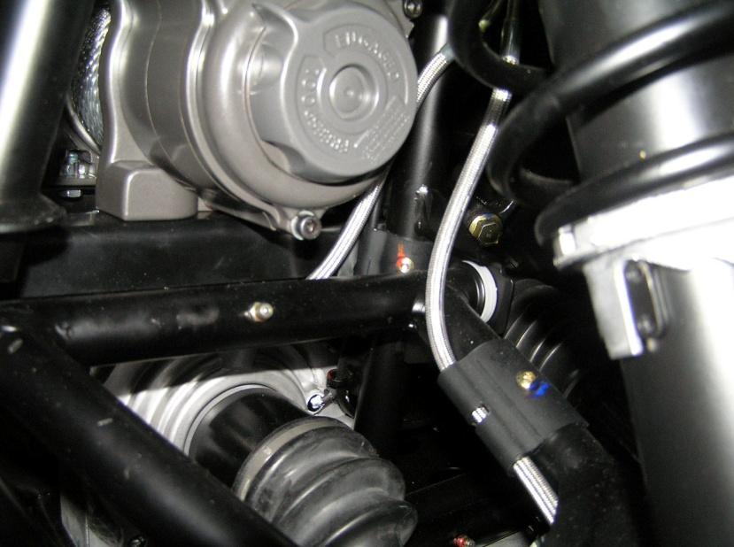
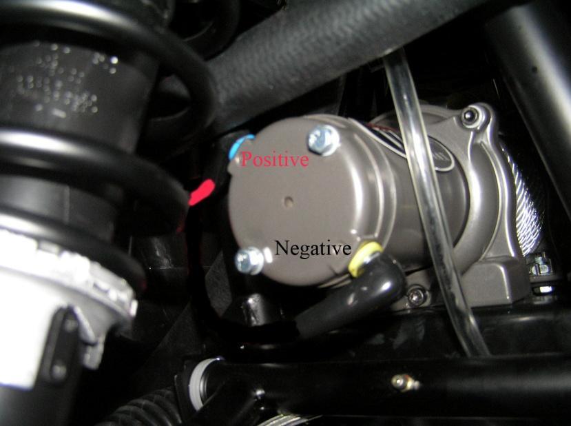
3 3. Run the power wires. Take the long set of red/black power wires and attach the red wire to the winch s red terminal and the black wire to the silver terminal. Keep the wire away from moving suspension parts. We left wire loose as we went down the upper frame. When fastening any wire where moisture could cause problems put dielectric tune-up grease (Permatex from NAPA) on all connections. Also if you want extra vibration protection, Napa has plastic split loom tube conduct that can also be installed over the wire after it has been routed through the frame. (Napa #737300, 3/8 split loom) Connecting the wire to the contactor, you will want the red wire attached to the red nut on the winch motor to go to the blue terminal on the contactor. (Blue is painted on top of the contactor terminal). The black wire attached to the silver terminal on the winch goes to the yellow terminal on contactor. If you get this wiring backwards this will not damage anything, the control switch will just work in reverse. 4. Now the power wires can be run. Take the long set of red/black power wires and attach the red wire to the winch s red terminal and the black wire to the silver terminal. Keep the wire away from moving suspension parts. We left wire loose as we went down the upper frame. When fastening any wire where moisture could cause problems put dielectric tune-up grease (Permatex from NAPA) on all connections. Also if you want extra vibration protection, Napa has plastic split loom tube conduct that can also be installed over the wire after it has been routed through the frame. (Napa #737300, 3/8 split loom) Connecting the wire to the contactor, you will want the red wire attached to the red nut on the winch motor to go to the blue terminal on the contactor. (Blue is painted on top of the contactor terminal). The black wire attached to the silver terminal on the winch goes to the yellow terminal on contactor. If you get this wiring backwards this will not damage anything, the control switch on handlebars will just work in reverse. 5. Next, run the power wires from the battery into the compartment or location you have chosen for your contactor. The red wire goes to the positive terminal on the battery and the red terminal on the contactor. The black wire goes negative terminal on the battery and the black terminal on contactor. We didn t attach the red wire until all the rest of the wiring was complete. Caution! It is easier to reverse the polarity at the battery then you would think and that can cause damage to your voltage regulator, contactor, and can start fires. The battery is capable of supplying a lot of current even to a short @motoalliance.com
4 6. The last of the wiring is to mount and wire in the control switch onto your dash. We wrapped a couple wraps of electrical back tape on the handlebars before we clamped the switch down. Route the control wiring down the vertical wiring harness and join up with the power cable on left side of cowling. Keep the red wire that hangs out near switched 12-volt wire. Route the control wire down to the power wire and follow the power wire back to the contactor location. Fasten the green wire to the green wire on contactor and the black wire to the black wire on the contactor. (The connectors can t be reversed.) 7. The red switch control wire is the next item, which often raises some questions. The red control wire hanging out of the control cable near the switch goes to the switch 12 volts on the ATV. Some ATV s will have an accessory wire provided and it is spelled out in the owner s manual. The wire will be fused for it. The wires can be many different colors. On Polaris the Red/white wires are fused accessory wires and Orange/white on later models. Under the front cover ¾ of the up on left side as sitting on the ATV, there will be a stubbed Red and white wire with heat shrink. Cut heat shrink away and use a crimp on spade connector and plug right into the wire. You could also call an your service center & they will give you the location and color wire for winch control, switch 12 volts wires over the phone. A factory service manual will also have the schematic in it. We found the switch 12 volts by using a 12-volt test light. We poked a hole though the insulation. With the test light clipped to the frame we turned on the key and lit the light. We turn turned off the key and light went out. (Switched 12 volts are defined as 12 volts is removed with the key off, as opposed to battery 12 volts that has power all the time. You can always find switch 12 volts on the backside of the ignition switch.) You may obtain a crimp on side tap terminal for taping into insulated wire at an Auto parts store or hardware store. We bared the insulation and soldered the red wire to the 12-volt wire. We used RTV Silicone on the joint and wrapped it in electrical tape. Some manufacturers provide a connector to plug into under the front access panel. Usually a crimp on spade connector will mate with it. 8. The last of the wiring is to mount and wire in the control switch on the dash (optional). Drill two holes in the dash, using the switch housing as a template. Remove nuts from side bolts, fasten switch to dash and attach with the materials of your choice from your local hardware store. We suggest two fender washers and a rubber grommet @motoalliance.com

5 9. Drill a hole for the wiring and use the grommet to protect the wire before feeding it through. Keep the red wire that hangs out near switched 12-volt wire. Route the control wire down to the power wire and follow the power wire back to the contactor location. Fasten the green wire to the green wire on contactor and the black wire to the black wire on the contactor. (The connectors are gender specific and can t be reversed.) 10. Lastly, fasten down the contactor with the bolts provided in the winch box. Make sure the 10-MM terminal nuts are tight on the contactor and wire terminal lugs and not shorting. Double check the green and black control wires on the contactor. They can mate hard, so make sure they are seated. Then, attach the battery wires to the battery. Your winch is operational. With the ignition key on, the relay should click when the handle bar control switch is activated. You should test both halves of the switch. The click is independent of winch powering 12 volts. It will click even if the battery is not wired to the contactor or winch. Wind in excess winch steel cable by carefully guiding it to the spool @motoalliance.com
6 6
7 7
8 8
9 9
MOTOALLIANCE WINCH MOUNT
 , / 1-866-527-7637 www.motoalliance.com MOTOALLIANCE WINCH MOUNT Polaris Sportsman 600 & 700 Thank you for purchasing our MotoAlliance winch mount(s). You now own a premium custom winch mount to allow
RZR WINCH KIT KIT P/N
 RZR WINCH KIT KIT P/N 2878787; 2879334 Application All RZR Models except RZR XP Before you begin, read these instructions twice and check to be sure all parts and tools are accounted for. Please retain
RANGER MIDSIZE WINCH KIT
 RANGER MIDSIZE WINCH KIT P/N 2881669 APPLICATION ALL MY RANGER 400; MY11 AND NEWER RANGER 500 EXCEPT CREW BEFORE YOU BEGIN Read these instructions thoroughly and make sure all parts and tools are accounted
INSTALLATION INSTRUCTIONS
 INSTALLATION INSTRUCTIONS Accessory Application Publication No. MII 15249 WINCH MOUNT KIT P/N 08L70-HL3-A41 SXS700/M4/M2 Issue Date September 2015 PARTS LIST No. Description Qty (1) Winch bracket 1 (2)
INSTALLATION INSTRUCTIONS
 Accessory Application Publication No. INSTALLATION INSTRUCTIONS WINCH MOUNT KIT P/N 08L77-HL3-A00 SXS700M4/M2 Honda Dealer: Please give a copy of these instructions to your customer. MII 14607 Issue Date
Polaris RANGER 800 Syle Mount
 Part #: 101330 Hardware Kit: HK-056, HK-031 Kit Components: Qty Part Description 1. Winch Mount 1... Fairlead Bracket 1... Fairlead Converter Bracket 6.... 3/8 x 1 HF Bolt 6. 3/8 SAE Flat Washers 8. 3/8
Tusk UTV Horn & Signal Kit Installation Instructions
 Tusk UTV Horn & Signal Kit Installation Instructions The Tusk UTV signal kit is designed to be a simple way to provide front and rear turn signals, license plate mount with light, horn, and rearview mirrors
Turn Signal / Horn Kit PN 7101 by All years Polaris RZR 1000 and RZR 900, 900-4, 900 trail, 900S and 900XC STOP - THIS KIT IS DESIGNED
 All years Polaris RZR 1000 and 1000-4 2015 RZR 900, 900-4, 900 trail, 900S and 900XC STOP - THIS KIT IS DESIGNED SPECIFICALLY FOR ALL YEAR AND MODEL POLARIS RZR 1000 AND 1000-4. ALSO THE 2015 POLARIS RZR
Ford Super Duty F-250, F and up
 Ford Super Duty F-250, F-350 2005 and up Installing Upfitter Switches by Richard L. Ray If you want to add a few aftermarket options to your new Ford Super Duty, Ford Motor Company makes things easy for
POLARIS RANGER XP 900/570 Winch Mount
 POLRIS RNGER XP 900/570 Winch Mount Part #: 101345 Hardware Kit: HK-305, HK-031 Contents: 1x 101021 Winch Mount Plate 1x 101023 Replacement Grill Wide 1x Fairlead Converter Bracket Hardware Kit: 3x 5/16-18
Electric Life JE18-KIT 2007 and up Jeep Wrangler 4 door Installation Instructions
 Installing the motor and regulator assembly Electric Life JE18-KIT 2007 and up Jeep Wrangler 4 door Installation Instructions 1. Remove door panels. Remove inner door panel. 2. With window lowered, remove
Assembly Instructions
 Assembly Instructions Part Number Description Model Approx. Assembly Time 99994-0903 Windshield Wiper Kit Mule SX 1 Hour WARNING Improper installation of this accessory could result in an accident causing
POLARIS SPORTSMAN ACE
 POLARIS SPORTSMAN ACE Winch Mount PART # 101180 Hardware Kit: HK-040, HK-031 Kit Components: Qty. Part Description 1... Winch Mount Plate (101181) 1... Winch Guard (101184) 1... Winch Spacer Kit (101210)
YAMAHA VIKING WINCH MOUNT
 YAMAHA VIKING WINCH MOUNT Verify style of winch you will be installing, 4 hole standard (3.0 x 4.875 ) will fit without any modification. Two hole style (3.10 apart) and Wide 4 hole (3 x 6.60 ) will require
Installation MKIV Headlight Housings with Fog Lamps (Procedures apply to both MKIV Jetta and Golf)
") Page 1 This tutorial is provided as a courtesy by ECS Tuning. Service Procedure Installation Proper service and repair procedures are vital to the safe, reliable operation of all motor vehicles as well
Page 1 This tutorial is provided as a courtesy by ECS Tuning. Service Procedure Installation Proper service and repair procedures are vital to the safe, reliable operation of all motor vehicles as well
LGT-311L Bumper LED Light Kit EZ-Go RXV Installation Instructions
 LGT-311L Bumper LED Light Kit EZ-Go RXV Installation Instructions Caution: Please read through the instructions carefully. Before starting this project, remove the system s positive and negative connections
INSTALLATION INSTRUCTIONS
 Accessory Application Publication No. INSTALLATION INSTRUCTIONS WINCH MOUNT P/N 08L73-HL4-F01 After 16 SXS1000M3/M3P/M3LE SXS1000M5P/M5D/M5LE MII 16083 Issue Date February 2017 PARTS LIST No. Description
POLARIS RZR 900/1000/TURBO/GENERAL
 POLARIS RZR 900/1000/TURBO/GENERAL Winch Mount PART # 101350 Hardware Kit: HK-034, HK-031, HK-318 Kit Components: Qty. Part Description 1... Winch Mount Plate (101351) 1... Standard Fairlead Plate (101221)
Installation Instructions
 Installation Instructions AMP RESEARCH Power Step by Bestop Automatic Retracting Running Board Vehicle Application Nissan Titan King Cab 2004 and newer (5 ft.) Part Number: 75106-01 Nissan Titan Crew Cab
INSTALLATION INSTRUCTIONS
 INSTALLATION INSTRUCTIONS Accessory Application Publication No. WINCH MOUNT P/N 08L74-HR3-A20 After 13 TRX420 (All except TRX420FA/FPA) After 13 TRX500 (All except TRX500FA/FPA) MII 15067 Issue Date Revised:
Zeon Control Pack Relocation Kit 78 Cable Length
 ORIGINAL INSTRUCTIONS SYMBOL INDEX SYMBOL EXPLANATION SYMBOL EXPLANATION Read All Product Literature Always Wear Leather Gloves Always Wear Hearing and Eye Protection Do Not Move People Zeon Control Pack
2013 Road King CVO FLHRSE5 Detachable Fairing w/ Garmin Zumo 665 Installation Instructions
 2013 Road King CVO FLHRSE5 Detachable Fairing w/ Garmin Zumo 665 Installation Instructions 1 1. Turn ignition switch to on position and leave there. This will prevent alarm from going off when you disconnect
INSTALLATION INSTRUCTIONS
 INSTALLATION INSTRUCTIONS ULTIMATE BULL BAR APPLICATION: 2016-2018 Chevrolet Silverado 1500 2016-2018 GMC Sierra 1500 PART NUMBER: 32-3870, 32-3875, 32-3870L, 32-3875L, 32-3920, 32-3925. ITEM QUANTITY
Brake and Tail Light Kit Workman 1100/2100 and Twister Utility Vehicles
 Form No. 5-90 Brake and Tail Light Kit Workman 00/00 and Twister Utility Vehicles Part No. 0 6697 Installation Instructions Important Before installing this kit, you must have Wiring kit number 99 79 installed
(31 ) ZEON CONTROL PACK RELOCATION KIT
 ZEON CONTROL PACK RELOCATION KIT") ORIGINAL INSTRUCTIONS SYMBOL INDEX (31 ) ZEON CONTROL PACK RELOCATION KIT SYMBOL EXPLANATION Read All Product Literature SYMBOL EXPLANATION Always Wear Leather Gloves INSTALLATION GUIDE Always Wear Hearing
ORIGINAL INSTRUCTIONS SYMBOL INDEX (31 ) ZEON CONTROL PACK RELOCATION KIT SYMBOL EXPLANATION Read All Product Literature SYMBOL EXPLANATION Always Wear Leather Gloves INSTALLATION GUIDE Always Wear Hearing
Installing Ignition Coil relay
 Installing Ignition Coil relay Above is a schematic diagram of the coil relay modification. All it really does is, it uses the existing 12 Volt positive that normally powers the coils, to power a relay,
Setting the World s Performance Standards
 Setting the World s Performance Standards 743 East Iona Road, Idaho Falls, ID 83401, (208) 529-0244 Fax (208) 529-9000 Forced Air Hot Air Elimination Kit (Bed Fan Kit) For 800 RZR-4 P/N 67-165 Kit Contents:
WOT Box Installation Instructions VW / Audi
 Connector Pinout Pin Color AWG Name WOT Box Installation Instructions VW / Audi Description 1 Yellow 18 RPM Connect to Fuel Injector Drive Signal or Ignition Control Signal (varies by car model) 2 Black
Aux. Battery and Isolator
 Aux. Battery and Isolator ISOLATOR MOUNTING ALL YEAR VANAGONS Fig.1 1. Disconnect ground from main battery under passenger seat 2. Remove driver seat 3. Remove driver seat belt buckle from seat pedestal
INSTALLATION INSTRUCTIONS
 INSTALLATION INSTRUCTIONS HDX LED GRILLE APPLICATION: 06-07 Toyota Tacoma PART NUMBER: 34-065 ITEM QUANTITY DESCRIPTION TOOLS NEEDED HDX GRILLE 0MM SOCKET 8 M6 HEX NUT (YELLOW ZINC) 3 8 M6 SPLIT LOCK WASHER
HARNESS KIT 3 PORT ISOLATION MODULE LIGHT SYSTEM. Parts List and Installation Instructions CAUTION
 May 1, 2018 Lit. No. 92991, Rev. 00 HARNESS KIT 3 PORT ISOLATION MODULE LIGHT SYSTEM Parts List and Installation Instructions Read this document before installing the snowplow. See your sales outlet/website
Dodge Ram 09-Current CS-DTR SERIES BACKUP CAMERA INSTALLATION
 Dodge Ram 09-Current CS-DTR SERIES BACKUP CAMERA INSTALLATION Thank you for your purchase! These instructions cannot possibly cover every option group for every model year of RAM trucks so you may find
JOHN DEERE GATOR SWITCH PANEL INSTRUCTIONS FITS 1GTRXUV2 AND 1GTRXUV4 CABS (p/n: 1XUVSP)
") P. 1 of 5 JOHN DEERE GATOR SWITCH PANEL INSTRUCTIONS FITS 1GTRXUV2 AND 1GTRXUV4 CABS (p/n: 1XUVSP) Note: Harness Extension Kit Required for 4 Passenger (p/n: 1XUV4WHEK) This manual is the property of the
P. 1 of 5 JOHN DEERE GATOR SWITCH PANEL INSTRUCTIONS FITS 1GTRXUV2 AND 1GTRXUV4 CABS (p/n: 1XUVSP) Note: Harness Extension Kit Required for 4 Passenger (p/n: 1XUV4WHEK) This manual is the property of the
LPE C5 Battery Relocation Kit
 LPE C5 Battery Relocation Kit The LPE C5 Corvette battery relocation kit improves vehicle weight distribution by moving weight to the rear of the vehicle. The improved weight distribution increases traction
3500 WINCH KIT P/N APPLICATION BEFORE YOU BEGIN KIT CONTENTS. P/N Rev 01 06/15 Page 1 of 11
 3500 WINCH KIT P/N 2881671 APPLICATION RZR XP 1000 ALL MODEL YEARS, 900 MY15 AND NEWER BEFORE YOU BEGIN Before you begin, read these instructions twice and check to be sure all parts and tools are accounted
Installation Manual P / P / P A / P B / P C E N G I N E B R A K E S
 Manual A p p l i c a t i o n : D e t r o i t D i e s e l S e r i e s 6 0 P - 6 1 / P - 6 3 / P - 6 3 A / P - 6 3 B / P - 6 3 C E N G I N E B R A K E S 5 If the engine is equipped with an aluminum valve
Lethal Performance Dual FPDM Harness Kit Installation
 Lethal Performance Dual FPDM Harness Kit Installation The Lethal Performance Dual FPDM Harness Kit is a plug-and-play modification. Depending on whether you are using the Lethal Performance wire upgrade
INSTALLATION INSTRUCTIONS
 INSTALLATION INSTRUCTIONS PARTS LIST Accessory Application Publications No. TRX420 (All) MII 13032 WINCH KIT P/N 08L94-HP5-100 Accessory Weight 35 lbs (16 kg) Honda Dealer: Please give a copy of these
INSTALLATION INSTRUCTIONS
 AUTOMOTIVE PRODUCTS, INSTALLATION INSTRUCTIONS ULTIMATE BULL BAR APPLICATION: 2009-2018 Dodge Ram 1500 (Excl. Rebel Model) 2019 Dodge Ram 1500 Classic PART NUMBER: 32-1960, 32-1965, 32-1960L, 32-1965L
POLARIS 4500 HD WINCH KIT
 POLARIS 4500 HD WINCH KIT P/N 2883860 APPLICATION Verify accessory fitment at Polaris.com. BEFORE YOU BEGIN Read these instructions and check to be sure all parts and tools are accounted for. Please retain
Gentex Homelink Installation Instructions
 Gentex Homelink Installation Instructions Kit Contents: Item Qty Part Description 1 Number GENK-41 NVS Homelink Mirror GENK-42 NVS Homelink w/mood lights 1 of the GENK-45 NVS Homelink w/compass following
LGT-306L / LB Club Car Precedent LED Light Bar Bumper Kit Installation Instructions
 LGT-306L / LB Club Car Precedent LED Light Bar Bumper Kit Installation Instructions Caution: Please read through the instructions carefully. Before starting this project, remove the system s positive and
WINCH MOUNT KIT FOR POLARIS RANGER P/N ASSEMBLY / OWNERS MANUAL. Application WINCH KIT NO. 25-9xxx
 WINCH MOUNT KIT FOR POLARIS RANGER P/N 25-3370 ASSEMBLY / OWNERS MANUAL Application WINCH KIT NO. 25-9xxx Before you begin, please read these instructions and check to be sure all parts and tools are accounted
Installation Instructions
 Installation Instructions Jeep JK 2-Door (2011 Present) Mounting Bracket and Air Line System Kit for ARB On-Board Twin Air Compressor (CKMTA12) Made in the USA Kit Contents: 1 Flat Bracket 1 Formed Bracket
Part Number: TTU-BGB14-DRL TTU-BGP14-DRL
 11/15/16 TOYOTA TUNDRA 2014-17 Billet Grille w/led DRL Part Number: TTU-BGB14-DRL TTU-BGP14-DRL Kit Contents Item # Quantity Reqd. Description 1 2 LED DRL 2 1 Driver Box 3 1 Switch 4 1 User Card 5 2 Hardware
WARNING WARNING WARNING. Warnings and Cautions MOVING PARTS ENTANGLEMENT HAZARD CHEMICAL AND FIRE HAZARD FALLING OR CRUSHING HAZARD
 Warnings and Cautions As you read these instructions, you will see S, S, NOTICES and NOTES. Each message has a specific purpose. S are safety messages that indicate a potentially hazardous situation, which,
INSTALLATION INSTRUCTIONS
 INSTALLATION INSTRUCTIONS HDX LED GRILLE APPLICATION: 013-017 Dodge Ram 1500 PART NUMBER: 34-1035 ITEM QUANTITY DESCRIPTION TOOLS NEEDED 1 1 HDX LED GRILLE 10MM SOCKET,3 UPPER BRACKET A, DRIVER () AND
RZ3-5K Polaris RZR XP 1000 & 900 Kicker 5 Speaker Audio Kit
 PO H PWER PO 5 O KIT I E D U A S A TS S I R LA R Z R R O SP pg 2 pg 9 pg 13 pg 25 pg 29 Disassembly, Wire and Amplifier Plate Installation Glovebox Subwoofer Installation Kick Panel Speakers Installation
Depress each tab as you pull the bezel off. The bezels are tight. L.H. shown.
 2013-2014 Ford Mustang V6 & Boss 302 Lower Valance Fog Light Kit Parts List: Quantity: Tool List: Fog light & bulb with bracket 2 Flat head & Phillips screwdriver Black bezels 2 Ratchet & Socket set OR
Smittybilt Gen2 XRC 9,500,lb. Winch Manufacturer Part Number Model Number J106786
 Smittybilt Gen2 XRC 9,500,lb. Winch Manufacturer Part Number 97495 Model Number J106786 Installation Time: 1 hour Tools Required: Work Light Box Cutter 10mm Open End Wrench 13mm Open End Wrench 14mm Open
INSTALLATION INSTRUCTIONS
 AUTOMOTIVE PRODUCTS, INC. INSTALLATION INSTRUCTIONS ULTIMATE BULL BAR APPLICATION: 2017 Ford F-250/350 PART NUMBER: 32-3900, 32-3905, 32-3900L, 32-3905L ITEM QUANTITY DESCRIPTION TOOLS NEEDED 1 1 ULTIMATE
RZ3-5A Polaris RZR XP 1000 & 900 SSV Works 5 Speaker Audio Kit
 RZ3-5A Polaris RZR XP 1000 & 900 SSV Works 5 Speaker Audio Kit pg 2 Disassembly, Wire and Amplifier Plate Installation pg 9 Glovebox Subwoofer Installation pg 13 Kick Panel Speakers Installation pg 25
Honda Pioneer 1000 Turn Indicator Kit
 Honda Pioneer 1000 Turn Indicator Kit Thank you for purchasing XTC Power Products Turn Signal System. Our Turn System is unique from the other kits on the market. Our Kit is plug and play with only power
TOOL SERVICE PARTS SVC CONTENTS ITEM QTY DESCRIPTION PART NUMBER 1 1 CUTTING TOOL EXTRACTION TOOL GENERAL APPLICABILITY
 TOYOTA COROLLA, MATRIX/ PONTIAC VIBE PART NUMBER: 250-1731 TOOL SERVICE PARTS CRUISE CONTROL KIT 1 3 2 1 BASE KIT CONTENTS ITEM QTY DESCRIPTION 1 1 CONTROL SWITCH ASSEMBLY 2 2 SCREWS (M5) 3 3 HARDWARE
ATV/UTV WINCH INSTRUCTION BOOK 3000 LBS
 ATV/UTV WINCH INSTRUCTION BOOK 3000 LBS As you read these instructions, you will see WARNINGS and CAUTIONS. Each message has a specific purpose. WARNINGS and CAUTIONS identify the hazard, indicate how
TOYOTA TACOMA FOG LIGHT (Halogen or LED)
") Part Number: TTA-312 / TTA-812 Kit Contents Item # Quantity Reqd. Description 1 2 Fog Lamps 2 1 Switch Assembly 3 1 Fog light operation guide 4 1 Harness bag Hardware Bag Contents Item # Quantity Reqd.
Part Number: TTA-312 / TTA-812 Kit Contents Item # Quantity Reqd. Description 1 2 Fog Lamps 2 1 Switch Assembly 3 1 Fog light operation guide 4 1 Harness bag Hardware Bag Contents Item # Quantity Reqd.
Installation Instructions
 Installation Instructions Jeep JK Unlimited (2007 Present) Mounting Bracket and Air Line System Kit for ARB On-Board Twin Air Compressor (CKMTA12) Made in the USA Kit Contents: 1 Bracket for ARB Compressor
pg 2 Disassembly, Wire and Amplifier Plate Installation pg 9 Glovebox Subwoofer Installation pg 13 Kick Panel Speakers Installation
 RZ3-5KRC RZR XP1000 & 2015+ RZR900 with Ride Command SSV Works 5 Speaker Audio Kit pg 2 Disassembly, Wire and Amplifier Plate Installation pg 9 Glovebox Subwoofer Installation pg 13 Kick Panel Speakers
DirectMount EXHAUST BRAKES
 DirectMount EXHAUST BRAKES APPLICATION: Fixed Orifice and PRXB Exhaust Brakes 2003 2005 Dodge Trucks with 3.5" & 4" Exhaust and 47RE & 48RE Automatic Transmissions Only Vehicles with an existing air compressor
RESPA -CF/CFX Installation Kit for Komatsu D475A-5E0
 Sy-Klone part number: REV3K13 Installation Time: 7 to 8 hours Purpose: RESPA systems preclean and filter air through integrated Gideon power precleaning technology. Filtration is provided by a MERV 16
(31 ) ZEON CONTROL PACK RELOCATION KIT
 ZEON CONTROL PACK RELOCATION KIT") Warn Industries, Inc. 12900 S.E. Capps Road Clackamas, OR USA 97015-8903 1-503-722-1200 FAX: 1-503-722-3000 www.warn.com Customer Service / Service Clients: 1-800-543-9276 International Sales Support /
Warn Industries, Inc. 12900 S.E. Capps Road Clackamas, OR USA 97015-8903 1-503-722-1200 FAX: 1-503-722-3000 www.warn.com Customer Service / Service Clients: 1-800-543-9276 International Sales Support /
2015 Ford F150 Front Bumper w/ LED
 PARTS LIST: 2015 Ford F150 Bumper w/ LED 1 Bumper Assembly 4 8mm Lock Washers 1 Driver/left L Bracket (center LED light) 2 8mm Hex Nuts 1 Passenger/right L Bracket (center LED light) 2 6mm x 20mm Button
Gentex by VOXX Corporation Installation Instructions
 KIT CONTENTS: Item Qty Part Number Description 1 1: ADVGEN20A 7 Pin Auto-Dimming Mirror with Compass and Temperature 2 1 Gentex by VOXX Corporation Installation Instructions Contact VOXX Customer Service
Installation Items: Cruise Module
 Installation Items: Rostra 250-1223, Electronic Cruise Control System (ECCS) includes the cruise module, harness, cruise cable, cruise module mounting bracket, cruise cable mounting bracket and hardware
INSTALLATION INSTRUCTIONS Winch Mounting Kit Winch Mount Kit: Application: Kawasaki Brute Force
 INSTALLATION INSTRUCTIONS Winch Mounting Kit Winch Mount Kit: 70207 Application: Kawasaki Brute Force Your safety, and the safety of others, is very important. To help you make informed decisions about
HARNESS KIT 3 PORT ISOLATION MODULE LIGHT SYSTEM
 September 1, 2016 Lit. No. 73981, Rev. 00 73977 HARNESS KIT 3 PORT ISOLATION MODULE LIGHT SYSTEM Parts List and Installation Instructions Read this document before installing the snowplow. See your sales
WINCH MOUNT KIT FOR POLARIS RANGER P/N ASSEMBLY / OWNERS MANUAL. Application WINCH KIT NO. 25-9xxx
 WINCH MOUNT KIT FOR POLARIS RANGER P/N 25-3300 ASSEMBLY / OWNERS MANUAL Application WINCH KIT NO. 25-9xxx Before you begin, please read these instructions and check to be sure all parts and tools are accounted
V8 Gen. V Ford Mustang 2010 Update
 V8 Gen. V Ford Mustang 2010 Update There were several updates to the Ford Mustang in the 2010 model year. This document outlines the differences between the installation steps necessary for the 2010 Mustang
OLDSMOBILE CUTLASS
 1971-72 OLDSMOBILE CUTLASS Four Panel Sequential LED Tail Light Kit Installation Guide Kit Contents: 4 LED panels 1 Connector/Wire Kit 1 Grommet/Boot Kit 1 Power wire 2 Pigtail Harness Kits 1 Crimp terminal
HARNESS KIT 3 PORT ISOLATION MODULE LIGHT SYSTEM
 September 1, 2016 Lit. No. 73980, Rev. 01 73973 HARNESS KIT 3 PORT ISOLATION MODULE LIGHT SYSTEM Parts List and Installation Instructions Read this document before installing the snowplow. See your sales
2-row and All-row systems included.
 Ag Leader Technology Cotton Picker Installation Installation Instructions for John Deere cotton picker models: 2-row and All-row systems included. IMPORTANT: Ensure the model numbers shown above correspond
INSTALLATION INSTRUCTIONS
 INSTALLATION INSTRUCTIONS Honda Dealer: Please give a copy of these instructions to your customer. PARTS LIST (15) (8) (12) (14) (13) (10) (11) (18) (17) (1) Accessory Application Publications No. TRX500FA/FGA
REAR ROOF SPEAKER KIT
 REAR ROOF SPEAKER KIT P/N 2882876 APPLICATION Verify accessory fitment at Polaris.com. BEFORE YOU BEGIN Read these instructions and check to be sure all parts and tools are accounted for. Please retain
BX8848 Installation Instructions 4 Diode Wiring Kit For Motorhomes With Red Tail Lights
 For Motorhomes With Red Tail Lights WARNG: Incorrect wiring may result in blown fuses, damaged wiring, fire, or bodily injury. Blue Ox recommends installation of this kit by a trained professional. Blue
SCION FRS FOG LIGHTS. Part Number: SFR-313
 Part Number: SFR-313 Kit Contents Item # Quantity Reqd. Description 1 2 Light Housings 2 2 Fog Light bezels 3 1 Harness bag 4 1 User s card 5 1 Switch 6 1 Fuse jumper Hardware Bag Contents Item # Quantity
AUXILIARY BATTERY BOX INSTALLATION INSTRUCTIONS
 AUXILIARY BATTERY BOX INSTALLATION INSTRUCTIONS The original TOMMY GATE hydraulic lift Assembling the Auxiliary Battery Box 1. Remove the cover from the auxiliary battery box by removing the two nuts and
Kawasaki Mule Pro FXT Winch Mount
 Kawasaki Mule Pro FXT Winch Mount Part #: 101230 Hardware Kit: HK-129, HK-031 Contents: 1x 101231 - Winch Mount 1x 101236 - Support Channel Hardware Kit: 4x 3/8-16 x 1-1/4 Hex Flange Bolt 2x 3/8-16 x 1
Kit INSTALLATION GUIDE. 5 psi Low Pressure Sensor (Single Gauge)
") ª Kit 25592 5 psi Low Pressure Sensor (Single Gauge) MN-333 (131107) ECR 7119 INSTALLATION GUIDE For maximum effectiveness and safety, please read these instructions completely before proceeding with installation.
ª Kit 25592 5 psi Low Pressure Sensor (Single Gauge) MN-333 (131107) ECR 7119 INSTALLATION GUIDE For maximum effectiveness and safety, please read these instructions completely before proceeding with installation.
HARNESS KIT 3 PORT ISOLATION MODULE LIGHT SYSTEM
 January 1, 2016 Lit. No. 92935, Rev. 01 52101 HARNESS KIT 3 PORT ISOLATION MODULE LIGHT SYSTEM Parts List and Installation Instructions Read this document before installing the snowplow. See your sales
Not Included. Rear Half Harness
 Basic Light Kit 60102 Caution! Wear appropriate eye protection! Disconnect the battery or batteries. Place run/tow switch in tow position before disconnecting the batteries on models using that feature.
INSTALLATION INSTRUCTIONS ATV WINCH MULTI-MOUNT Multi-Mount Mounting-Kit: PN Application: YAMAHA GRIZZLY 660
 INSTALLATION INSTRUCTIONS ATV WINCH MULTI-MOUNT Multi-Mount Mounting-Kit: PN 63172 Application: YAMAHA GRIZZLY 660 As you read these instructions, you will see NOTES, CAUTIONS and WARNINGS. Each message
TOYOTA PRIUS FOG LIGHT (Halogen or LED)
") Part Number: TPR-413 / TPR-813 Kit Contents Item # Quantity Reqd. Description 1 2 Fog Lamps 2 1 Lower Grill 3 1 Switch Assembly 4 1 Fog Light Operation guide 5 1 Harness Bag Hardware Bag Contents Item
Part Number: TPR-413 / TPR-813 Kit Contents Item # Quantity Reqd. Description 1 2 Fog Lamps 2 1 Lower Grill 3 1 Switch Assembly 4 1 Fog Light Operation guide 5 1 Harness Bag Hardware Bag Contents Item
IT IS IMPORTANT THAT YOU OBTAIN THE CORRECT INFORMATION FOR YOUR VEHICLE, OR DAMAGE TO THE WIRING SYSTEM COULD OCCUR.
 Instructions for Universal Harness PRINT THESE INSTUCTIONS Gentex Mirror Installation Instructions Provided by www.rearviewautomirrors.com These instructions have been prepared to provide you with details
LGT-312L E-Z-Go TXT Light Bar Bumper Kit Installation Instructions
 LGT-312L E-Z-Go TXT 2014+ Light Bar Bumper Kit Installation Instructions Caution: Please read through the instructions carefully. Before starting this project, remove the system s positive and negative
C FORD F250 / F L POWERSTROKE DIESEL WITH AUTOMATIC TRANSMISSIONS ONLY
 EXHAUST BRAKES C40019 1999-2003 FORD F250 / F350 7.3L POWERSTROKE DIESEL WITH AUTOMATIC TRANSMISSIONS ONLY Getting Started Thank you and congratulations on your purchase of a Pacbrake exhaust retarder.
RZ3-3A Polaris RZR XP 1000 & 900 SSV Works 3 Speaker Audio Kit
 RZ3-3A Polaris RZR XP 1000 & 900 SSV Works 3 Speaker Audio Kit pg 2 Disassembly, Wire and Amplifier Plate Installation pg 9 Glovebox Subwoofer Installation pg 13 Kick Panel Speakers Installation pg 25
Model APS-101N Installation Manual
 Programmable Features Model APS-101N Installation Manual Select By Operating Transmitter Press Lock Button Press Unlock Button Siren Indications 1 Chirp 2 Chirps Factory Default 1) Arming Method Passive
Rostra Electronic Cruise Control Install On a Stratoliner or Roadliner
 Rostra Electronic Cruise Control Install On a Stratoliner or Roadliner MATERIALS LIST: 1 - Rostra Part # 250-1223 (www.brandondist.com/products/cruise1223.htm) 1 - Signal Splitter part # 250-4369 1 - Engagement
2010 FORD TRANSIT ELECTRONIC CRUISE KIT Part Number:
 General Applicability Recommended Tools Item # Qty. Description 1. 250-2758 1 Cruise Control Module 2. 250-2760 1 Switch Harness 3. 250-2759 1 Main Wiring Harness 4. 250-2771 1 Pedal Interface Harness
Raxiom Factory GPS Rear Back-up Camera Kit (07-17 Wrangler)
") Raxiom Factory GPS Rear Back-up Camera Kit (07-17 Wrangler) Installation Time: 2.5-3Hrs Tools Required: 7mm Socket & Driver 10mm Socket 10mm Open end wrench Knife / Razor blade Zip-ties Wire Cutters Needle
Raxiom Factory GPS Rear Back-up Camera Kit (07-17 Wrangler) Installation Time: 2.5-3Hrs Tools Required: 7mm Socket & Driver 10mm Socket 10mm Open end wrench Knife / Razor blade Zip-ties Wire Cutters Needle
Kit psi Low Pressure Sensor (Dual Gauge)
") ª Kit 25812 5 psi Low Pressure Sensor (Dual Gauge) MN-337 (111107) ECR 7119 INSTALLATION GUIDE For maximum effectiveness and safety, please read these instructions completely before proceeding with installation.
ª Kit 25812 5 psi Low Pressure Sensor (Dual Gauge) MN-337 (111107) ECR 7119 INSTALLATION GUIDE For maximum effectiveness and safety, please read these instructions completely before proceeding with installation.
INSTALLATION INSTRUCTIONS WINCH MOUNTING KIT Part Number: Application: Honda Rubicon/Foreman 500
 INSTALLATION INSTRUCTIONS WINCH MOUNTING KIT Part Number: 70830 Application: Honda Rubicon/Foreman 500 Your safety, and the safety of others, is very important. To help you make informed decisions about
HARNESS KIT 3 PORT ISOLATION MODULE LIGHT SYSTEM. w/projector-style VEHICLE LIGHTING. Parts List and Installation Instructions CAUTION
 June 1, 2018 Lit. No. 90725, Rev. 00 HARNESS KIT 3 PORT ISOLATION MODULE LIGHT SYSTEM w/projector-style VEHICLE LIGHTING Parts List and Installation Instructions Read this document before installing the
TOYOTA PRIUS C FOG LIGHT (Halogen & LED)
") TOYOTA PRIUS C 2012-14 FOG LIGHT (Halogen & LED) Part Number: TPC-312 / TPC-812 Kit Contents Item # Quantity Reqd. Description 1 2 Fog Lamps 2 2 Bezels 3 1 Switch Assembly 4 1 Fog Light Operation guide
TOYOTA PRIUS C 2012-14 FOG LIGHT (Halogen & LED) Part Number: TPC-312 / TPC-812 Kit Contents Item # Quantity Reqd. Description 1 2 Fog Lamps 2 2 Bezels 3 1 Switch Assembly 4 1 Fog Light Operation guide
Adjustable Light Kits E-Z-Go TXT All Models Installation Instructions
 Adjustable Light Kits E-Z-Go TXT All Models 1996-2013 Installation Instructions Caution: Please read through the instructions carefully. Before starting this project, remove the system s positive and negative
Heater/Defroster Installation Instructions
 1301 39 th Street NW, Suite 2 * Fargo, ND 58102 * Toll Free 866.764.0616 * Fax 701.446.0103 * www.gemcar.com Service Instructions Heater/Defroster Installation Instructions Models: All 2005 - Current Part
PHASE 3 POWERSPORTS AUDIO KIT RZR POLARIS. pg 2 Disassembly, Wire and Amplifier Plate Installation. pg 9 Glovebox Subwoofer Installation
 POLARIS RZR PHASE 3 POWERSPORTS AUDIO KIT pg 2 Disassembly, Wire and Amplifier Plate Installation pg 9 Glovebox Subwoofer Installation pg 13 Kick Panel Speakers Installation pg 25 MRB3 and Dash Kit Installation
GETTING STARTED: SOME RECOMMENDATIONS PLEASE TRY OUR WAY FIRST!
 RAINGEAR 1953/ 54 Chevrolet GETTING STARTED: SOME RECOMMENDATIONS PLEASE TRY OUR WAY FIRST! Note: This system is designed with built in adjustments to fit in your car. If, as you are installing it, you
RANGER 900 POWER STEERING KIT
 RANGER 900 POWER STEERING KIT P/N 2880083 APPLICATION MY14 AND NEWER RANGER XP 900 MODELS IMPORTANT It is strongly recommended that this kit be installed by an authorized Polaris dealer. NOTE Use of this
PN CHEVY TRI-FIVE. Kit Contents: Four panel Sequential LED Taillight kit installation guide
 Four panel Sequential LED Taillight kit installation guide Kit Contents: 2 tail light LED panels 2 tail light turn signal LED panels 1 rubber boot/sleeve kit 1 power wire with t-tap 1 driver side LED harness,