Self-Adjust Clutch Installation Guide
|
|
|
- Alberta Howard
- 6 years ago
- Views:
Transcription
1 Self-Adjust Clutch Installation Guide 0

 must be a minimum of 10. (See Fig. 1) Fig. 1 10 Fig. 2 Fig.")

2 STOP! READ CAREFULLY BEFORE INSTALLING CLUTCH This clutch must be installed by a qualified installer. Improper installation or failure to replace or resurface the flywheel, or to replace the pilot bearing, clutch brake or other worn drive train components may cause poor clutch release or early failure and void the manufacturer s warranty. Verify Correct Flywheel Dimensions Flywheel bore (DIM A) must be a minimum of 10. (See Fig. 1) Fig Fig. 2 Fig. 3 You must have a minimum of 5/16 distance from the friction surface (face) of your flywheel to the top of the bolt head that holds the flywheel to the crankshaft. If it is less than 5/16, you need a NEW flywheel! (See Fig. 3) Flywheel clutch pilot cannot be greater than 3/16 deep. If it is greater than 3/16 the clutch will not bolt tight to flywheel. (See Fig. 2) October
 on the input shaft between the clutch brake and the transmission.")
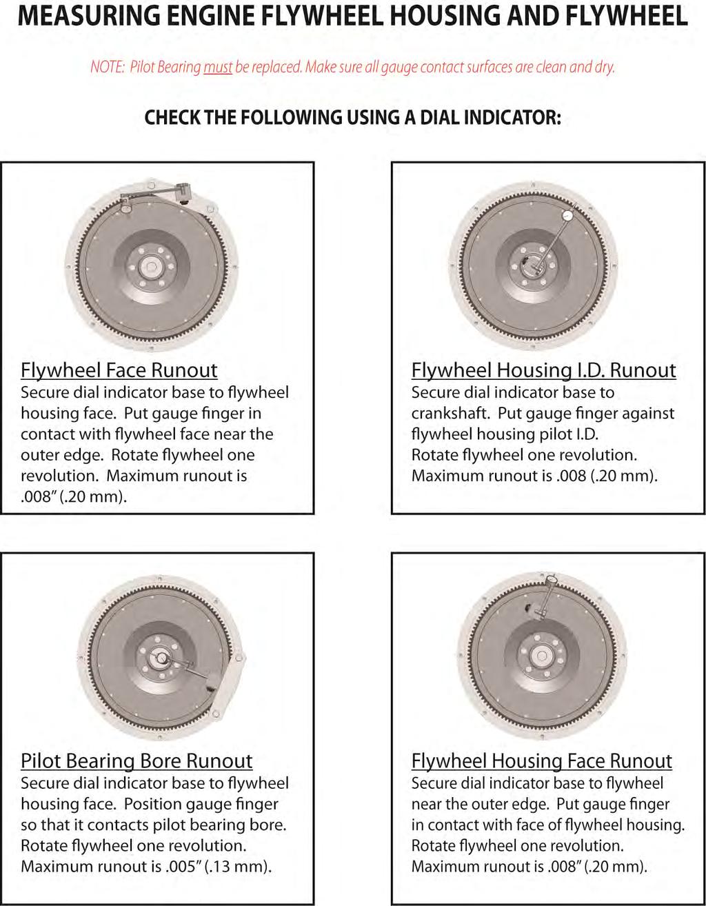
3 INSTALLATION 1. Resurface or replace flywheel. Surface must be smooth or premature clutch failure can occur. REMEMBER: Machining the flywheel past the recommended.060 moves the pressure plate away from the transmission. In this event, install a fiber spacer (provided) on the input shaft between the clutch brake and the transmission. The release yoke in the bell housing may not align properly with the pressure plate release bearing housing. Linkage adjustment may be required during clutch setup. If resurfacing is required, while the flywheel is mounted to the crank shaft, verify correct flywheel dimensions as seen in Fig. 2 and Fig Inspect and dial-indicate the mating surface of engine flywheel housing and clutch bell housing for alignment. Check flywheel run out. CAUTION: If misalignment is greater than the recommended limits, this will cause poor clutch release, rapid wear on transmission input shaft and destruction of the clutch disc. Excessive flywheel run out may cause severe vibration in vehicle drive line. (See Fig. 5) 3. A new pilot bearing with a VITON seal must be used. Before installing pilot bearing into flywheel, check freedom of movement on transmission input shaft. 4. Verify disc fits in flywheel bore (Fig. 1). Slide disc the length of the input shaft checking for twist and wear. Insert alignment shaft through bearing housing. Install rear disc (oriented correctly), center plate, and front disc (oriented correctly) on alignment shaft. Move clutch housing towards flywheel making sure cover fits into flywheel pilot. 5. Install the bolts (7/16 x 14unc x 2-1/4) that fasten the clutch housing on the flywheel. Tighten the bolts to the specified torque and the sequence specified by the manufacturer of the vehicle or transmission (Recommended ft*lbs). Bolts should be Grade 5 or greater. 6. Remove caging fork from under the release bearing. Remove alignment shaft. Verify bearing distance from cover is 1/2-5/8 (See Fig. 4). NOTE: Any time the clutch is removed from the flywheel, the caging fork needs to be reinstalled. Failure to do so will cause adjusting arm to fall out of retainer stud. See Fig. 9 in Reset Procedure. Fig. 4 DIM B 1/2-5/8 2
4 Fig. 5 3
. 10.")
5 7. Reconnect lube hose attachment (For Hydraulic Linkage Systems). 8. Examine transmission input shaft and clutch release system components for wear and replace if necessary. (See Fig. 6) 9. Install fiber spacer and replace clutch brake (fiber spacer not needed if over-sized clutch brake is used). 10. Be sure to properly lube the following components with NLGI grade 2 or 3 Lithium complex grease: Release Bearing, Yoke Fingers, Cross Shaft Bushings, and Linkage Pivot Points. Note: Applying enough grease to the release bearing until visible will extend the life of sleeve bushings and input shaft. Fig. 6 Release Yoke Worn fingers will cause sleeve bushing wear and adjustment problems Transmission Bearing Retainer Measured input shaft length should be If longer than 8.71 transmission bearing retainer cap needs to be replaced. Worn or rough surface will lead to premature clutch brake wear and adjustment problems Transmission Bearing Wear will allow input shaft wobble creating vibration which leads to premature failure Cross Shaft Bushing Worn cross shaft bushings allows sideways thrust on release bearing causing wear on sleeve bushing and premature wear on release bearing Fiber Spacer Cross Shafts and Linkage Worn cross shafts and linkage system can lead to adjustment problems, as well as, hard pedal and premature sleeve bushing wear Clutch Brake A clutch brake is used on non-synchronized transmissions to slow or stop the input shaft when the clutch pedal is depressed. A clutch brake is designed to work at engine idle with the truck stopped. Needs to be replaced at every clutch installation Input Shaft Splines Worn splines on input shaft will cause clutch to release improperly and may cause splined hubs in clutch disc to break out. Input Shaft Roughness in bushing area will lead to sleeve bushing failure and can cause bushing to pull out of sleeve Input Shaft Pilot Any wear in area will allow input shaft to wobble creating vibration which leads to premature failure 11. Using extreme caution, guide transmission through clutch cover, disc assemblies, and into pilot bearing rotating bell housing shaft so that release yoke fingers are clear of the pads on the release bearing assembly. (Warning: Transmission must not hang or be forced into the clutch. This can warp the clutch disc and prevent the clutch from releasing.) NOTE: Do not add lube to input shaft splines! 12. Start bell housing bolts and tighten progressively to the torque recommended by the vehicle manufacturer. 13. Install clutch linkage. See Clutch Set Up Procedure. 4
6 CLUTCH SET UP PROCEDURE NOTE: Clutches are adjusted at the factory to original equipment specifications and should require very little internal adjustment to achieve proper release and engagement. The clutch must not be adjusted to accommodate thin or worn flywheels, or worn linkage, yoke and/or cross shaft bushings, or to accommodate other drive train deficiencies. Adjustment for such purposes will either cause the clutch to not function properly or will cause early clutch failure and will be apparent on factory inspection of warranty claims, thereby voiding the manufacturer warranty. STEP #1 After transmission installation, check the clearance between the yoke tips and wear pads on bearing housing for 1/8 clearance. This determines pedal free play (Mechanical Linkage Only). (See Fig. 7) Adjust the clutch linkage to increase or decrease the yoke-to-bearing clearance. NEVER USE THE INTERNAL CLUTCH ADJUSTMENT FOR THIS PURPOSE. STEP #2 Check for proper clutch brake and bearing gap of 1/2 to 9/16. If the gap is too small verify DIM B (Fig. 4 or Fig. 7). If DIM B is correct and a fiber spacer or oversized clutch brake was installed, remove the fiber spacer and/or replace over-sized clutch brake with standard thickness clutch brake. NOTE: If the gap is larger than 9/16 and DIM B is correct then one of the following conditions exists. Fiber spacer/over-sized clutch brake was not installed or you need to re-measure input shaft length as seen in Fig. 6. DO NOT ADJUST THE CLUTCH! THIS DIMENSION IS CRITICAL. DO NOT VARY EITHER OVER OR UNDER THESE DIMENSIONS UNDER ANY CIRCUMSTANCES. REMINDER: The bearing must move a minimum of 1/2 or clutch will not release. Eliminate lost motion before checking for 1/2 movement. Lost motion is generally caused by loose or worn linkage, or worn yoke or cross shaft bushings. STEP #3 Verify the clutch brake squeeze by inserting.010 feeler gauge between bearing and clutch brake, then depressing the pedal to end of stroke. The feeler gauge must be tightly clamped between the bearing and the clutch brake. This verifies the contact of the bearing to the clutch brake. The clutch brake will be squeezed if the total pedal stroke slightly exceeds the movement required to move the yoke/fork 5/8 to 11/16 (the combined total of the 1/8 clearance between yoke tips and wear pads and the 1/2-9/16 brake squeeze gap). To optimize brake squeeze slowly let up on the pedal and check the pedal position at the moment the.010 feeler gauge can be removed. If the pedal is less than ½ or more than 1 from the floor when gauge can be removed, readjust the linkage. IN THE EVENT THE BRAKE IS NOT BEING SQUEEZED, DO NOT CHANGE THE 1/2-9/16 GAP FOR THE CLUTCH BRAKE, OR THE 1/8 CLEARANCE FOR THE BEARING HOUSING CONSULT THE VEHICLE MANUFACTURER SERVICE MANUAL. In analyzing the reasons for the brake not being squeezed, other things to check for are: A. Worn linkage components or yoke and cross shaft bushings. If necessary, replace those components. B. Improper linkage assembly. Verify that linkage is assembled in the correct hole locations. C. Pedal stroke. To adjust, raise the upper and/or lower the lower pedal stops. D. If the clutch is hydraulically assisted, make sure the slave and master cylinders are functioning properly. NOTE: MAXIMUM BRAKE SQUEEZE (IN CAB OF TRUCK) SHOULD NOT EXCEED 1 FROM THE END OF PEDAL STROKE. IF IT DOES, IT CAN BE ADJUSTED BY: A. Changing pedal stops in cab to reduce total pedal stroke. B. Increasing 1/8 yoke-to-bearing setting to lower squeeze. (This will increase free-pedal travel.) 5
, and 1/2-9/16 gap between")

7 STEP #4 Installer should carefully verify that there is 1/2-5/8 gap between clutch cover and release bearing, 1/8 of free travel between yoke and wear pads (mechanical linkage only), and 1/2-9/16 gap between release bearing and clutch brake. Schematic 1 Fig. 7 If Fiber Spacer is to be installed after transmission, notch V as shown in Schematic 1 O.D. 2 I.D. 1.5 Fiber Spacer 1/2-5/8 DIM 1/2-9/16 1/8 (Mechanical Linkage Only) 6
8 TROUBLESHOOTING AND DIAGNOSTICS Bearing Position too large (Greater than 5/8 ) Disc in Backwards 5/16 flywheel dimension is too small and disc is hitting crank bolts (See Fig. 3) Flywheel bore is smaller than 10 (See Fig. 1) Bearing Position too small (Less than 1/2 ) Flywheel not resurfaced Flywheel Clutch Pilot is more than 3/16 (See Fig. 2) Forgot to install a disc NOTE: If any of the previous situations occur, verify the adjuster arm is still inserted in stud (see Fig. 9) Bearing to Clutch Brake Gap is greater than 9/16 Verify Bearing Position is in spec between 1/2-5/8 (See Fig. 7) Input shaft measurement is too long/excessive wear on transmission input bearing retainer (See Fig. 6) Did not use Over-Sized clutch brake or fiber spacer Self-Adjust mechanism not working See Reset Procedure Bearing to Clutch Brake Gap is less than 1/2 Verify bearing position is in spec between 1/2-5/8 ( See Fig. 7) Used over-sized clutch brake instead of standard clutch brake Have fiber spacer and don t need it Free Travel is out of spec (Mechanical Linkage Systems Only) Verify Bearing Position is in spec between 1/2-5/8 (See Fig. 7) Verify Bearing to Brake Gap is in spec between 1/2-9/16 (See Fig. 7) 7
 2. Disengage clutch 3. Install manual adjust mechanism (Fig. 8) 4.")

9 RESET PROCEDURE RESET PROCEDURE If for any reason the clutch needs to be reset or manually adjusted, follow the instructions below. 1. Remove self-adjusting mechanism (Fig. 8) 2. Disengage clutch 3. Install manual adjust mechanism (Fig. 8) 4. Manually adjust clutch to meet specs in set up procedure. (See Fig. 7) 5. Reinstall self-adjusting mechanism. Ensure adjusting arm is properly seated in the retainer stud as seen in Fig When reinstalling self-adjusting mechanism it may be necessary to manually ratchet the self-adjust mechanism so that the worm gear is seated properly in the adjusting ring teeth. Fig. 8 Incorrect Fig. 9 Correct 8
10 9
Clutch Installation Guide
 Clutch Installation Guide 0 STOP! READ CAREFULLY BEFORE INSTALLING CLUTCH This clutch must be installed by a qualified installer. Improper installation or failure to replace or resurface the flywheel,
Tech Note Truck 14 & 15.5 Twin Plate Cast Iron Type Installation Guidelines
 1. (14 & 15.5 ) Check condition of the flywheel. Grind to resurface or replace flywheel. Surface MUST BE machined or premature clutch failure can occur. Flywheel depth must be 2.938 (74.62mm) for 14 (350mm)
HEAVY-DUTY CLUTCH CATALOG
 RoadChoice.com HEAVY-DUTY CLUTCH CATALOG Table of Contents BENEFITS AND FEATURES OF OUR CLUTCHES Road Choice 15.5 Clutch Assembly...... 4 Cryogenically Treated Disc Springs....... 5 Determining the Proper
SACHS Clutches The Intelligent Choice for the Long Haul
 SACHS Clutches The Intelligent Choice for the Long Haul Twin XTend Clutch Installation Objectives: Identification Operation Tools Installation Troubleshooting Identification 15.5 Self Adjusting Clutch
Troubleshooting. Pull Type Clutches - Poor Release
 Troubleshooting Pull Type Clutches - Poor Release Complaint Possible Causes Corrective Action Poor Release Intermediate plate sticking on drive lugs due to cocked drive pins (AS and EP 1402 only) (see
ALL-MAKES HEAVY-DUTY CLUTCHES
 ALL-MAKES HEAVY-DUTY CLUTCHES Alliance Truck Parts has over 30 product lines that serve the commercial transportation industry with reliable new and remanufactured parts and accessories for all makes and
EUCLID SELF-ADJUSTING CLUTCH
 EUCLID SELF-ADJUSTING CLUTCH Euclid self-adjusting clutches deliver uncompromising quality because precisionengineering goes into every unit. Our partner-supplier utilizes ISO 9001 quality control in every
Clutches for Automobiles and Light Trucks
 Clutches for Automobiles and Light Trucks What does the Clutch do? Connects the engine torque to transmission when ENGAGED Unhooks engine from transmission when DISENGAGED Where is the driver s foot when
Bulletin: CLIB Date: February 4, Bulletin Type: Service. Topic: Eaton Clutch Performance Evaluation and Set-up
 Bulletin: CLIB-0014 Date: February 4, 2011 Bulletin Type: Service Topic: Eaton Clutch Performance Evaluation and Set-up Issue Description: The purpose of communicating this information is to provide details
CROWERGLIDE AUTOMATIC CLUTCH Instruction Manual
 CROWERGLIDE AUTOMATIC CLUTCH Instruction Manual Crower Cams & Equipment Co., Inc 6180 Business Center Court San Diego, CA. 92154 Phone: 619.661.6477 ext. 148 Fax: 619.690.7846 www.crower.com TABLE OF CONTENTS
CONCEPT 10.5 DUAL DISC INSTALLATION INSTRUCTIONS
 CONCEPT 10.5 DUAL DISC INSTALLATION INSTRUCTIONS Congratulations on your purchase of the RAM Concept 10.5 Dual disc clutch system. Please completely read and carefully follow the setup instructions, and
Service Manual. LL30002 Rev. 7/03. HEAVY DUTY PUSH/PULL TYPE CLUTCHES
 Service Manual LL30002 Rev. 7/03 HEAVY DUTY PUSH/PULL TYPE CLUTCHES www.haldex.com Table of Contents Section One - Push Type Clutches Clutch Assembly Cutaway Detail............................1 Clutch
Clutch Kit Install Guide
 Jack up and support the car on jack stands Remove the exhaust system (some models) Remove the driveshaft (rear wheel drive) Remove CV axle (front wheel drive) Manual transmission removal Clutch Kit Install
CLUTCH 6-1 CLUTCH CONTENTS
 TJ CLUTCH 6-1 CLUTCH CONTENTS page GENERAL INFORMATION CLUTCH COMPONENTS... 1 INSTALLATION METHODS AND PARTS USAGE... 1 DESCRIPTION AND OPERATION CLUTCH OPERATION... 1 DIAGNOSIS AND TESTING DIAGNOSTIC
1994 Mazda MX-5 Miata. CLUTCH 1994 Clutch
 CLUTCH 1994 Clutch DESCRIPTION Miata uses a hydraulically operated clutch. HYDRAULIC SYSTEM BLEEDING 1. Remove bleeder screw cap, located at clutch release cylinder. Install vinyl hose onto bleeder screw.
CLUTCH 6-1 CLUTCH CONTENTS
 Z CLUTCH 6-1 CLUTCH CONTENTS page page CLUTCH DIAGNOSIS... 2 CLUTCH SERVICE... 9 CLUTCH COMPONENTS MECHANICAL COMPONENTS The clutch mechanism in Grand Cherokee models with manual transmission consists
Transmission Overhaul Procedures-Bench Service
 How to Assemble the Lower Reverse Idler Gear Assembly Special Instructions In 1996 Eaton changed the reverse idler system design. In the nut design, the reverse idler bearing was lubricated through a hole
Diagnostic Procedures
 Section 6 Diagnostic Procedures Learning Objectives: 1. Describe manual transmission, transaxle and transfer case component inspection and diagnostic procedures 2. Identify clutch component inspection
SECTION 5B MANUAL TRANSMISSION TABLE OF CONTENTS
 SECTION 5B MANUAL TRANSMISSION TABLE OF CONTENTS General Description and Operation... 5B-2 Shift Lever... 5B-2 Transmission Assembly... 5B-2 Specifications... 5B-3 Diagnostic Information and Procedures...
Series 1000 and Cutout
 17.15.Remove the belt from the tractor. NOTE: There were a small number of tractors made using a CVT drive and a 2-speed (L-H-N-R) GT transaxle. The belt must pass over the center mounted gear selector
ATASA 5 th Study Guide Chapter 36 Pages Clutches 74 Points. Clutches. Be Certain to Read the Summary
 ATASA 5 th Study Guide Chapter 36 Pages 1071 1091 74 Points Be Certain to Read the Summary 1. The provides a mechanical coupling between the engine s & the transmission s shaft. The clutch allows the engine
DRAGON CLAW SHELBY 26 SPLINE
 DRAGON CLAW 13-14 5.4 SHELBY 26 SPLINE *This Kit Requires a Min. 1 ⅝ in. Working Input Shaft Splines. *Professional Installation recommended *Power/Air tools NOT advised 1. Remove transmission assembly
 www.clubsuprafrance.com CLUTCH 1996 Toyota Supra 1995-96 Clutch Supra DESCRIPTION The single, dry-type disc clutch uses a hydraulicallyoperated master cylinder with a clutch release cylinder mounted on
Transmission Input Bearing Retainer
 34 Transmission Input Bearing Retainer Clutch Cover / Intermediate Plate Fig 11 Failure - Damaged Sleeve Bushing Failure to center the input shaft with the sleeve of the release bearing assembly, when
Clutch System Troubleshooting Guide-Service Tips
 DESCRIPTION AND OPERATION Clutch System The purpose of the clutch is to connect and disconnect a manually operated transmission and the remainder of the powertrain system from the engine. This permits
1992 Clutch. Eclipse, Expo/Expo LRV, Galant, Mirage, Precis, 3000GT
 Article Text ARTICLE BEGINNING 1992 Clutch Eclipse, Expo/Expo LRV, Galant, Mirage, Precis, 3000GT DESCRIPTION All clutches are single disc type. Pressure plate assembly uses a diaphragm spring to engage
ENGINE CLUTCH CONTENTS OF THIS SECTION
 ENGINE CLUTCH 6C-l ENGINE CLUTCH CONTENTS OF THIS SECTION SUBJECT General Description Periodic Service Adjustments on Car Removal of Clutch Inspection of Clutch Parts Installation of Clutch Specifications
Clutch Diagrams. Easy-Pedal Heavy Duty Clutch
 Clutch Diagrams Easy-Pedal Heavy Duty Clutch Clutch Diagrams Solo Adjustment-Free Heavy Duty Clutch Table of Contents Section 1: Introduction Factors that Effect Clutch Performance.................................................
HAYS HYDRAULIC RELEASE BEARING INSTALLATION INSTRUCTIONS
 HAYS HYDRAULIC RELEASE BEARING INSTALLATION INSTRUCTIONS PRELIMINARY INSTALLATION NOTES IMPORTANT! DO NOT RETURN THIS PRODUCT TO YOUR DISTRIBUTOR. If you have questions, please review additional information
MANUAL TRANSMISSION SERVICE
 MANUAL TRANSMISSION SERVICE Introduction Internal combustion engines develop very little torque or power at low rpm. This is especially obvious when you try to start out in direct drive, 4th gear in a
DRAGON CLAW PRE 86 BIG BLOCK CHEVY 10 SPLINE
 DRAGON CLAW PRE 86 BIG BLOCK CHEVY 10 SPLINE *This Kit Requires a Min. 1 ⅝ in. Working Input Shaft Splines. *Professional Installation recommended *Power/Air tools NOT advised 1. Inspect input shaft splines
Module 6: Air Foundation Brakes
 Air Brakes Terms and Definitions Basic Components That Make Up Air Foundation Brakes Types of Air Foundation Brakes Parts of a Cam Foundation Brake Parts of a Wedge Foundation Brake Parts of a Disc Foundation
Clutch Installation Guidelines Follow Service Manual Instructions For Step-By- Step Procedures
 9700063 Revision 12/20/10 Clutch Installation Guidelines Follow Service Manual Instructions For Step-By- Step Procedures FAILURE TO FOLLOW PROPER INSTALLATION OR BREAK-IN PROCEDURES WILL VOID ANY WARRANTY
Borg & Beck Clutch Information
 Borg & Beck Clutch Information After the clutch is bolted to the flywheel, under no circumstance should the release lever, or the release lever plate if equipped, be pulled away from the flywheel against
Failure Diagnosis. The LuK guide to troubleshooting clutch system failures and malfunctions on agricultural vehicles
 Failure Diagnosis The LuK guide to troubleshooting clutch system failures and malfunctions on agricultural vehicles Contents Page Failure diagnosis / causes of failures Clutch fault diagnosis What is clutch
CLUTCH. Section IV DATA AND SPECIFICATIONS CHRYSLER SERVICE MANUAL. Page. Clutch Pedal Adjustment 74. Clutch Disassembly 77. Clutch Assembly 78
 CLUTCH 73 Section IV CLUTCH Page Clutch Pedal Adjustment 74 Clutch Disassembly 77 Clutch Assembly 78 Service Diagnosis 81 DATA AND SPECIFICATIONS MODEL TYPE 1376 (Borg-Beck) Single Plate, Dry Disc FACINGS
CLUTCH CONTENTS SERVICE DIAGNOSIS. (a) Worn or damaged disc assembly. (b) Grease or oil on disc facings. (c) Improperly adjusted cover assembly.
 Worn or damaged disc assembly. (b) Grease or oil on disc facings. (c) Improperly adjusted cover assembly.") CLUTCH CONTENTS -GROUP 6 Page CLUTCH HOUSING ALIGNMENT... 6 CLUTCH PEDAL FREE PLAY 1 CLUTCH RELEASE BEARING 5 CLUTCH RELEASE FORK... 5 CLUTCH SERVICING 2 PILOT BUSHING CRANKSHAFT TO TRANSMISSION DRIVE
CLUTCH CONTENTS -GROUP 6 Page CLUTCH HOUSING ALIGNMENT... 6 CLUTCH PEDAL FREE PLAY 1 CLUTCH RELEASE BEARING 5 CLUTCH RELEASE FORK... 5 CLUTCH SERVICING 2 PILOT BUSHING CRANKSHAFT TO TRANSMISSION DRIVE
DIAGNOSIS AND TESTING Procedure revision date: 05/18/2000. SYMPTOM CHART TRANSMISSION, MANUAL Condition Possible Source Action
 SYMPTOM CHART TRANSMISSION,... SYMPTOM CHART TRANSMISSION, MANUAL (TRANSMISSION, MANUAL, M5OD) Section 07 03: Transmission, Manual, M5OD 1996 Aerostar/Ranger/Explorer Workshop Manual DIAGNOSIS AND TESTING
Brake System H TX, H2.0TXS [B475]; H TX [B466] Safety Precautions Maintenance and Repair
![Brake System H TX, H2.0TXS [B475]; H TX [B466] Safety Precautions Maintenance and Repair](/thumbs/86/93834005.jpg "Brake System H TX, H2.0TXS [B475]; H TX [B466] Safety Precautions Maintenance and Repair") HMM180001 Brake System H1.5-1.8TX, H2.0TXS [B475]; H2.5-3.5TX [B466] Safety Precautions Maintenance and Repair When lifting parts or assemblies, make sure all slings, chains, or cables are correctly fastened,
HMM180001 Brake System H1.5-1.8TX, H2.0TXS [B475]; H2.5-3.5TX [B466] Safety Precautions Maintenance and Repair When lifting parts or assemblies, make sure all slings, chains, or cables are correctly fastened,
GROUP 6 CLUTCH CONTENTS SPECIFICATIONS
 GROUP 6 CLUTCH CONTENTS Page CLUTCH 6-1 Specifications.... 1 Transmission Main Drive Pinion Pilot Bushing... 5 Special Tools. 1 Clutch Release Bearing 6 Torque Reference 1 Torque Shaft and Bearings...
TSM54/52 MANUAL TRANSMISSION
 3B-1 SECTION 00 3B TSM54/52 MANUAL TRANSMISSION Table of Contents GENERAL INFORMATION... 3B-3 Overview... 3B-3 Specifications... 3B-4 System components... 3B-5 Shifting mechanism... 3B-17 Diagnostic information
AUTOMATIC CLUTCH Models
 AUTOMATIC CLUTCH 1940 Models Source of this material is from 1940 Series, Issue 4, January 1940 Hudson Service Magazine AUTOMATIC CLUTCH 1940 MODELS The automatic clutch installation and adjustment procedure
Installation Instructions
 Preparing your vehicle to install your brake system upgrade 1. Rack the vehicle. 2. If you don t have a rack, then you must take extra safety precautions. 3. Choose a firmly packed and level ground to
page CLUTCH DIAGNOSIS 2
 6-1 CONTENTS page DIAGNOSIS 2 COMPONENTS MECHANICAL COMPONENTS The clutch mechanism in A D models with a gas or diesel engine consists of a single, dry-type clutch disc and a diaphragm style clutch cover.
70001 and Clutch Rebuild Instructions
 70001 and 70010 Clutch Rebuild Instructions Brinn, Incorporated 1615 Tech Drive Bay City, MI 48706 Telephone 989.686.8920 Fax 989.686.6520 www.brinninc.com Notice Use these instructions if you only want
22-1 GROUP 22 MANUAL TRANSAXLE CONTENTS MANUAL TRANSAXLE... 22A MANUAL TRANSAXLE OVERHAUL... 22B
 22-1 GROUP 22 MANUAL TRANSAXLE CONTENTS............................... 22A OVERHAUL..................... 22B 22A-2 GROUP 22A MANUAL TRANSAXLE CONTENTS GENERAL DESCRIPTION......... 22A-3 DIAGNOSIS 22A-6
Clutch Clut Fundament Fundamen als t Chapter 69
 Clutch Fundamentals Chapter 69 Objectives Describe the basic clutch parts Explain the operation of the clutch Compare differences in clutch hdesign Describe the different methods of releasing the clutch
EGR Performance Brakes Assembly Instructions DODGE DANA 70 '87 - '93 (Will not fit stock sized dual rear wheels)
") EGR Performance Brakes Assembly Instructions DODGE DANA 70 '87 - '93 (Will not fit stock sized dual rear wheels) Got Brakes? Parts List (2) Vented Rotors (2) Multi hole Cable Mount & L Brkt (2) Axle Tube
EGR Performance Brakes Assembly Instructions DODGE DANA 70 '87 - '93 (Will not fit stock sized dual rear wheels) Got Brakes? Parts List (2) Vented Rotors (2) Multi hole Cable Mount & L Brkt (2) Axle Tube
BRAKE SYSTEM Return To Main Table of Contents
 BRAKE SYSTEM Return To Main Table of Contents GENERAL... 2 BRAKE PEDAL... 10 MASTER CYLINDER... 13 BRAKE BOOSTER... 16 BRAKE LINE... 18 PROPORTIONING VALVE... 19 FRONT DISC BRAKE... 20 REAR DRUM BRAKE...
BASE PRESSURE AND STATIC ADJUSTMENT (COUNTERCLOCKWISE TO INCREASE)
") 10 INCH 6 LEVER SPECIFICATIONS AND PARTS LIST Warning: Be sure to remove the three 1/4"-20 socket head capscrews after installing the pressure plate. These keep the pressure plate from binding when removing
10 INCH 6 LEVER SPECIFICATIONS AND PARTS LIST Warning: Be sure to remove the three 1/4"-20 socket head capscrews after installing the pressure plate. These keep the pressure plate from binding when removing
CL - Clutch Replacement
 2003 3.2CL - Clutch Replacement Special Tools Required Pressure plate compressor 07AAE-P8EA000 Clutch alignment shaft 07AAF-P8EA000 Pressure plate compressor adapter 07AAK-P8EA000 Ring gear holder 07LAB-PV00100
DIAGNOSIS AND TESTING
 DIAGNOSIS AND TESTING SUSPENSION AND STEERING SYSTEM 2007 SUSPENSION Suspension - Nitro CONDITION POSSIBLE CAUSES CORRECTION FRONT END NOISE 1. Loose or worn wheel bearings. 1. Replace wheel bearings.
CARBONETIC Carbon Clutch operating instructions
 ACROSS USA INC www.carbonetic.net TEL:310-635-3555 CARBONETIC Carbon Clutch operating instructions Thank you very much for your purchase of the CARBONETIC carbon clutch. Please read these instructions
The Reaper Owners Manual Foreword Warning!!! Never Never Stall Speed Stall Speed Chart
 The Reaper 12-1-04 Owners Manual Foreword The Reaper is a centrifugal disc clutch designed to mount on a ¾ crankshaft or jackshaft for race karts with engines up to 20hp. This manual will help you gain
Magnesium Option, Late Model Front Seal, Viton, P/N 67256V Rear Seal, Viton, P/N 67257V Shifter Installed Heat Treated Yoke, P/N
 DESCRIPTION OPTION Magnesium Option, Late Model 80100L Front Seal, Viton, P/N 67256V 80109 Rear Seal, Viton, P/N 67257V 80110L Shifter Installed 80112L Heat Treated Yoke, P/N 62946-6 80119-6 Heat Treated
CAMARO/FIREBIRD
 CAMARO/FIREBIRD 1967-1969 TKO 5-SPEED MANUAL TO MANUAL TRANSMISSION CONVERSION INSTALLATION MANUAL FOLLOW FACTORY SERVICE MANUAL (FSM) RECOMMENDED SAFETY PRECAUTIONS. TRANSMISSION REMOVAL AND INSTALLATION
South Bend Ford/Dodge DD
 South Bend Ford/Dodge DD Installation Instructions Torque specifications: Flywheel to crank 90-100 ft. lbs. Pressure plate to flywheel is 45 ft. lbs. Unbolt pressure plate from flywheel in a star pattern
TRANSMISSION AND TRANSFER CASE
 DR TRANSMISSION AND TRANSFER CASE 21-1 TRANSMISSION AND TRANSFER CASE TABLE OF CONTENTS page MANUAL TRANSMISSION- G56- SERVICE INFORMATION...1 MANUAL TRANSMISSION- GETRAG 238- SERVICEINFORMATION...69 MANUAL
1967 (Late) CORVETTE STANDARD (NON-ADJUSTABLE) STEERING COLUMN DISASSEMBLY & REPAIR INSTRUCTIONS PAPER #2
 CORVETTE STANDARD (NON-ADJUSTABLE) STEERING COLUMN DISASSEMBLY & REPAIR INSTRUCTIONS PAPER #2") Last Revision: 03SE2012 1967 (Late) - 1968 CORVETTE STANDARD (NON-ADJUSTABLE) STEERING COLUMN DISASSEMBLY & REPAIR INSTRUCTIONS PAPER #2 Disassembly and Repair Instructions Addressed in this Paper Degree
Last Revision: 03SE2012 1967 (Late) - 1968 CORVETTE STANDARD (NON-ADJUSTABLE) STEERING COLUMN DISASSEMBLY & REPAIR INSTRUCTIONS PAPER #2 Disassembly and Repair Instructions Addressed in this Paper Degree
Cylinder Installation Compression/Stripper, for Models, 22HF, 16HF, 1600 machines
 Knowledge Base Article Type: Instructions Cylinder Installation Compression/Stripper, for Models, 22HF, 16HF, 1600 machines Description: Instructions on How to properly install stripper beam and compression
MOPAR B-BODY
 MOPAR B-BODY 1962-1970 TKO 5-SPEED MANUAL TO MANUAL TRANSMISSION CONVERSION INSTALLATION MANUAL FOLLOW FACTORY SERVICE MANUAL (FSM) RECOMMENDED SAFETY PRECAUTIONS. TRANSMISSION REMOVAL AND INSTALLATION
DIM Drive Train Systems
 2014 NATEF JOB TASKS COMPLETION REQUIREMENT: P1-95% P2-70% P3-25% Student Name: DETAILED COURSE CONTENT II. DRIVE TRAIN A. CLUTCH -- The student will be able to: P1 P2 P3 Level Date 1. Identify causes
ProLine. 44 Mower. for 120 Traction Unit. Model No & Up. Operator s Manual
 FORM NO. 9 ProLine Mower for 0 Traction Unit Model No. 05 99000 & Up Operator s Manual IMPORTANT: Read this manual carefully. It contains information about your safety and the safety of others. Also become
 AUTOGARD SERIES 820 TORQUE LIMITER Installation and Maintenance Manual DB0009 Issue 11 21 Feb 2017 British Autogard Ltd 2 Wilkinson Rd., Love Lane Industrial Estate, Cirencester, Glos., GL7 1YT UK Tel.
CAMARO/FIREBIRD
 CAMARO/FIREBIRD 1970-1981 TKO 5-SPEED MANUAL TO MANUAL TRANSMISSION CONVERSION INSTALLATION MANUAL FOLLOW FACTORY SERVICE MANUAL (FSM) RECOMMENDED SAFETY PRECAUTIONS. TRANSMISSION REMOVAL AND INSTALLATION
Spring-Engaged/Hydraulically-Released BD Caliper Brake. (i) MTY (81) QRO (442) MEX (55)
 MTY (81) QRO (442) MEX (55)") Spring-Engaged/Hydraulically-Released BD Caliper Brake (i) FORM NO. L-07-E-0300 In accordance with Nexen s established policy of constant product improvement, the specifications contained in this manual
Spring-Engaged/Hydraulically-Released BD Caliper Brake (i) FORM NO. L-07-E-0300 In accordance with Nexen s established policy of constant product improvement, the specifications contained in this manual
CHEVROLET NOVA
 CHEVROLET NOVA 1962-1967 TKO 5-SPEED MANUAL TO MANUAL TRANSMISSION CONVERSION INSTALLATION MANUAL FOLLOW FACTORY SERVICE MANUAL (FSM) RECOMMENDED SAFETY PRECAUTIONS. TRANSMISSION REMOVAL AND INSTALLATION
Sisu S-Cam Drum Brakes
 Sisu S-Cam Drum Brakes (For hub reduction rear axles since 1992) Maintenance Manual Sisu Axles, Inc. Autotehtaantie 1 P.O. Box 189 FIN-13101 Hämeenlinna Finland Phone int + 358 204 55 2999 Fax int + 358
OWNERS MANUAL. GMC C K AND 19K GVW CHASSIS CAB 2004-NEWER MODELS (Link Part No. 8M000050) PROUDLY INSTALLED BY : COMPANY : INSTALLER SIGNATURE :
 PROUDLY INSTALLED BY : COMPANY : INSTALLER SIGNATURE :") OWNERS MANUAL GMC C5500 15K AND 19K GVW CHASSIS CAB 2004-NEWER MODELS (Link Part No. 8M000050) Link Mfg. Ltd. 223 15th St. N.E. Sioux Center, IA USA 51250-2120 (712) 722-4868 Fax (712) 722-4779 QUESTIONS?
OWNERS MANUAL GMC C5500 15K AND 19K GVW CHASSIS CAB 2004-NEWER MODELS (Link Part No. 8M000050) Link Mfg. Ltd. 223 15th St. N.E. Sioux Center, IA USA 51250-2120 (712) 722-4868 Fax (712) 722-4779 QUESTIONS?
TRANSMISSION AND TRANSFER CASE
 XJ TRANSMISSION AND TRANSFER CASE 21-1 TRANSMISSION AND TRANSFER CASE TABLE OF CONTENTS page AX5 MANUAL TRANSMISSION... 1 NV3550 MANUAL TRANSMISSION... 42 AUTOMATIC TRANSMISSION 30RH... 88 page AW 4 AUTOMATIC
9 POWER TAKE-OFF 9.1 REAR ENGINE POWER TAKE-OFF (REPTO) ASSEMBLY FRONT MOUNTED POWER TAKE-OFF
 ASSEMBLY FRONT MOUNTED POWER TAKE-OFF") 9 POWER TAKE-OFF Section Page 9.1 REAR ENGINE POWER TAKE-OFF (REPTO) ASSEMBLY... 9-3 9.2 FRONT MOUNTED POWER TAKE-OFF... 9-25 9-2 From Bulletin 4-50-02 6SE50 0006 Copyright 2002 DETROIT DIESEL CORPORATION
9 POWER TAKE-OFF Section Page 9.1 REAR ENGINE POWER TAKE-OFF (REPTO) ASSEMBLY... 9-3 9.2 FRONT MOUNTED POWER TAKE-OFF... 9-25 9-2 From Bulletin 4-50-02 6SE50 0006 Copyright 2002 DETROIT DIESEL CORPORATION
Service Bulletin Trucks Date Number Page
 Mack Trucks, Inc. Allentown, PA USA (Also applies to Mack Trucks Australia, Operation and Adjustment Only, CXX, CLX, CMH, CMM and CSM Models) (Supersedes SB313005 dated 03/24/08) Service Bulletin Trucks
Advanced Auto Tech. ASE A 3 Test Preparation Clutch & Drive Line Service
 Advanced Auto Tech ASE A 3 Test Preparation Clutch & Drive Line Service The clutch and the drive line both have their own unique symptoms and noises, separate from the transmissions used to change torque
F SERIES STARTER. thrust washer. STARTER DISASSEMBLY. to the starter motor. Remove cup. Remove starter pulley and spring. USE
 STARTER DISASSEMBLY Remove retainer ring, pinion stop washer, pinion spring and pinion gear from helix. Remove starter pulley and spring. USE CAUTION WHEN REMOVING SPRING. Remove three screws holding the
Precision Degree Wheel Kit
 555-81621 Precision Degree Wheel Kit Instruction Booklet Instructions for 81621 Camshaft Degree Kit Thank you for purchasing the Jegs Camshaft Degree Kit. Please follow these detailed instructions to properly
ENGINE TUNE-UP INSPECTION OF ENGINE COOLANT INSPECTION OF ENGINE OIL INSPECTION OF BATTERY. INSPECTION OF AIR FILTER (Paper Filter Type)
") ENGINE MECHANICAL - Engine Tune-Up EM-17 ENGINE TUNE-UP INSPECTION OF ENGINE COOLANT (See steps 1 and 2 on page CO-4) INSPECTION OF ENGINE OIL (See steps 1 and 2 on page LU-5) INSPECTION OF BATTERY (See
ENGINE MECHANICAL - Engine Tune-Up EM-17 ENGINE TUNE-UP INSPECTION OF ENGINE COOLANT (See steps 1 and 2 on page CO-4) INSPECTION OF ENGINE OIL (See steps 1 and 2 on page LU-5) INSPECTION OF BATTERY (See
HORSTMAN GREASED LIGHTNING CLUTCH
 HORSTMAN GREASED LIGHTNING CLUTCH Horstman s Greased Lightning (GL) clutch is designed for ultra high performance, and requires expert setup and a serious commitment to maintenance. Warning!!! 1. Clutch
SPECIAL TOOLS Dodge Pickup 5.9L Eng R3500. Fig 1: Identifying Remover C-3985-B (Special Tool) 9/6/13 Printer Friendly View
 9/6/13 Printer Friendly View") Procedures 2003 Dodge Pickup 5.9L Eng R3500 manual transmission SPECIAL TOOLS Fig 1: Identifying Remover C-3985-B (Special Tool) www2.prodemand.com/print/index?content=tabs&module=true&tab=true&terms=true&ymms=false&classname=
Procedures 2003 Dodge Pickup 5.9L Eng R3500 manual transmission SPECIAL TOOLS Fig 1: Identifying Remover C-3985-B (Special Tool) www2.prodemand.com/print/index?content=tabs&module=true&tab=true&terms=true&ymms=false&classname=
Maintenance Information
 80234313 Edition 1 June 2006 Air Grinder, Die Grinder, Sander and Belt Sander Series G1 (Angle) Maintenance Information Save These Instructions WARNING Always wear eye protection when operating or performing
Parking brake Mechanical brake acting on rear wheels
 11 Brake System 11.1 General SPECIFICATIONS EJTC0010 Master cylinder Type Tandem type I.D. mm(in.) 20.64 mm (0.813 in.) Fluid level warning sensor Provided Brake booster Type Vacuum Boosting ratio 4.0
MANUAL TRANS OVERHAUL - BORG-WARNER - T56 6-SPEED MANUAL TRANSMISSIONS Borg-Warner T56 (MM6) 6-Speed
 6-Speed") IDENTIFICATION MANUAL TRANS OVERHAUL - BORG-WARNER - T56 6-SPEED 1998 MANUAL TRANSMISSIONS Borg-Warner T56 (MM6) 6-Speed Transmission has 2 identification labels, located on lower left side of case. One
IDENTIFICATION MANUAL TRANS OVERHAUL - BORG-WARNER - T56 6-SPEED 1998 MANUAL TRANSMISSIONS Borg-Warner T56 (MM6) 6-Speed Transmission has 2 identification labels, located on lower left side of case. One
Clutch Diagnosis - Causes of Failure
 Clutch Diagnosis - Causes of Failure Guide Tube wear, Spline wear, Mainshaft Bearing wear Worn Flywheel Bearing, ridged or heat damaged Flywheel surface Worn/siezed Release Arm pivots, friction lining
1. General GENERAL CL-2
 SYSTEM GENERAL 1. General The clutch is of a dry, single plate type with a diaphragm spring. The clutch is a push type clutch. When the pedal is depressed, the release bearing will press the center of
Transmission Overhaul Procedures-Bench Service
 How to Install the Auxiliary Countershaft Assembly Special Instructions To make auxiliary section assembly easier, you can make an auxiliary section fixture out of a 2" x 12" piece of wood. 3' 1' 3" 4.56"
SYNCHRONIZE YNCHRONIZER AUTOMATIC TIC TROUBLESHOOTING GUIDE RELAY ASSEMBLY SOLENOID (MODEL 1750) LIMIT SWITCH ENGINE CABLE CABLE TO
 LIMIT SWITCH ENGINE CABLE CABLE TO") YNCHRONIZER SYNCHRONIZE AUTOMATIC TIC TROUBLESHOOTING GUIDE SOLENOID (MODEL 1750) RELAY ASSEMBLY LIMIT SWITCH ENGINE CABLE CABLE TO ENGINE THROTTLE RED COLLAR ADJUST LIMIT SWITCH OPERATION BRIDGE CABLE
YNCHRONIZER SYNCHRONIZE AUTOMATIC TIC TROUBLESHOOTING GUIDE SOLENOID (MODEL 1750) RELAY ASSEMBLY LIMIT SWITCH ENGINE CABLE CABLE TO ENGINE THROTTLE RED COLLAR ADJUST LIMIT SWITCH OPERATION BRIDGE CABLE
 YNCHRONIZER AUTOMATIC SYNCHRONIZE TROUBLESHOOTING GUIDE SOLENOID (MODEL 1750) RELAY ASSEMBLY LIMIT SWITCH ENGINE CABLE CABLE TO ENGINE THROTTLE RED COLLAR ADJUST LIMIT SWITCH OPERATION BRIDGE CABLE CONTROL
SUSPENSION 2-1 SUSPENSION CONTENTS
 ZJ SUSPENSION 2-1 SUSPENSION CONTENTS page ALIGNMENT... 1 FRONT SUSPENSION... 6 page REAR SUSPENSION... 14 ALIGNMENT INDEX page GENERAL INFORMATION WHEEL ALIGNMENT... 1 DIAGNOSIS AND TESTING SUSPENSION
TRANSMISSIONS MANUAL
 DMR-5023 Stick shift pilot bearing. Knurled for sure fit, self aligning for perfect fit and smooth running and shift. Fits ant GM manual stick transmission crank. Allows GM transmission in Ford cars. DMR-5022
CAUTION: Do not clean, wash or soak transmission seals in cleaning solvents. Dry all parts with compressed air.
 «1993 Thunderbird/Cougar Table of Contents» «Group 07: TRANSMISSION» «Section 07-03: Transmission, Manual--M5R2» «CLEANING AND INSPECTION» Transmission Cleaning CAUTION: Do not clean, wash or soak transmission
OVERHAUL. 1. INSPECT 1ST GEAR THRUST CLEARANCE (a) Using a feeler gauge, measure the 1st gear thrust clearance.
 Using a feeler gauge, measure the 1st gear thrust clearance.") 41135 OVERHAUL 4108901 1. INSPECT 1ST GEAR THRUST CLEARANCE (a) Using a feeler gauge, measure the 1st gear thrust clearance. 0.10 0.40 mm (0.0039 0.0157 in.) C68252 2. INSPECT 2ND GEAR THRUST CLEARANCE
41135 OVERHAUL 4108901 1. INSPECT 1ST GEAR THRUST CLEARANCE (a) Using a feeler gauge, measure the 1st gear thrust clearance. 0.10 0.40 mm (0.0039 0.0157 in.) C68252 2. INSPECT 2ND GEAR THRUST CLEARANCE
OWNERS MANUAL GM C4500/C5500 DANA MODEL S135 REAR AXLE 2003-NEWER MODELS LINK MFG. PART NO. 8M PROUDLY INSTALLED BY : COMPANY :
 OWNERS MANUAL GM C4500/C5500 DANA MODEL S135 REAR AXLE 2003-NEWER MODELS LINK MFG. PART NO. 8M000030 Link Mfg. Ltd. 223 15th St. N.E. Sioux Center, IA USA 51250-2120 (712) 722-4874 Fax (712) 722-4876 QUESTIONS?
Independent Front Suspension
 Independent Front Suspension Technical Training Contents Why Independent? Tuthill Models Features and Benefits Description Special Tools Regular Maintenance Troubleshooting Available Kits Contacting Tuthill
Geared Drives 200Z PSRU Zero Offset Gearbox with Centrifugal Clutch Assembly
 Instructions for Removing and replacing Gen X Gearbox with Geared Drives 200Z Prior to your gear box arriving: Using a strap or chain and an engine hoist to hold your engine up in the mount, remove your
MANUAL TRANSMISSION SECTION MT CONTENTS TRANSMISSION/TRANSAXLE MT-1 SERVICE INFORMATION POSITION SWITCH...13 Checking...13
 TRANSMISSION/TRANSAXLE SECTION MT A B MANUAL TRANSMISSION MT D CONTENTS E SERVICE INFORMATION... 2 PRECAUTIONS... 2 Service Notice or Precaution...2 PREPARATION... 3 Special Service Tool...3 Commercial
CLUTCH 6-1 CLUTCH TABLE OF CONTENTS
 PL CLUTCH 6-1 CLUTCH TABLE OF CONTENTS page DESCRIPTION AND OPERATION MODULAR CLUTCH ASSEMBLY....1 CLUTCH CABLE...1 CLUTCH INTERLOCK/UPSTOP SWITCH....1 DIAGNOSIS AND TESTING CLUTCH SYSTEM DIAGNOSIS...2
INSTRUCTION MANUAL IM-422 For HTC/COUPLING ASSEMBLY HC-8088
 No Revision 2/22/18 INSTRUCTION MANUAL IM-422 HTC/COUPLING ASSEMBLY The Riverhawk Company reserves the right to make changes updating this document without dissemination or notice. The latest revision
Installation Manual. Model T680A/B Engine Brakes. For Mack 6 Cylinder, 4 Valve Head E6 and E7 Series Engines. Engine Brakes
 Engine Brakes Installation Manual Model T680A/B Engine Brakes For Mack 6 Cylinder, 4 Valve Head E6 and E7 Series Engines TecBrake P.O. Box 27822 Houston, Texas 77227 INSTALLATION MANUAL TECBRAKE T680A
SUSPENSION 2-1 SUSPENSION CONTENTS
 WJ SUSPENSION 2-1 SUSPENSION CONTENTS page ALIGNMENT... 1 FRONT SUSPENSION... 4 page REAR SUSPENSION... 15 ALIGNMENT INDEX page AND WHEEL ALIGNMENT... 1 SERVICE PROCEDURES PRE-ALIGNMENT... 2 AND WHEEL
IMCO SCX SERIES INFORMATION, OPERATION & MAINTAINANCE
 IMCO SCX SERIES INFORMATION, OPERATION & MAINTAINANCE Warning! Warning! Warning! Danger! Warning! 1. SCX & SCX4 Drives will not fit on a standard gimbal helmet, IMCO HELMET: #05-8025 Black or #05-8027
AUTOMATIC TRANSMISSIONS Mitsubishi F3A20 Series TRANSMISSION APPLICATION TABLE
 Article Text ARTICLE BEGINNING AUTOMATIC TRANSMISSIONS Mitsubishi F3A20 Series APPLICATION TRANSMISSION APPLICATION TABLE Vehicle Application Transmission Model Colt 3-Speed (1990-94)... F3A21 Colt Vista