OWNERS MANUAL GM C4500/C5500 DANA MODEL S135 REAR AXLE 2003-NEWER MODELS LINK MFG. PART NO. 8M PROUDLY INSTALLED BY : COMPANY :
|
|
|
- Damian Dalton
- 5 years ago
- Views:
Transcription
1 OWNERS MANUAL GM C4500/C5500 DANA MODEL S135 REAR AXLE 2003-NEWER MODELS LINK MFG. PART NO. 8M Link Mfg. Ltd th St. N.E. Sioux Center, IA USA (712) Fax (712) QUESTIONS? CALL CUSTOMER SERVICE PROUDLY INSTALLED BY : COMPANY : INSTALLER SIGNATURE : DATE :
2 INSTALLATION INSTRUCTIONS INDEX 1.0 INTRODUCTION 2.0 DRIVER SIDE DISASSEMBLY 3.0 DRIVER SIDE ASSEMBLY 4.0 PASSENGER SIDE DISASSEMBLY 5.0 PASSENGER SIDE ASSEMBLY 6.0 LATERAL CONTROL ROD & STABILIZER BAR 7.0 AIR CONTROL SYSTEM 8.0 ELECTRICAL 9.0 FINAL INSPECTION & OPERATION 10.0 SERVICE & MAINTENANCE 2
3 1. INTRODUCTION IMPORTANT! It is important that the entire installation instructions be read thoroughly before proceeding with suspension installation. WARNING! A correct installation must result in the suspension and axle being loaded within the range specified by axle and suspension manufacturers. Please check vehicle specifications and intended usage to insure axle will be within Gross Axle Weight Rating (GAWR). No alteration of any suspension component is permitted. PRODUCT INSTALLER RESPONSIBILITIES Installer is responsible for installing the product in accordance with Link Mfg. specifications and installation instructions. Installer is responsible for providing proper vehicle components and attachments as well as required or necessary clearance for suspension components, axles, wheels, tires, and other vehicle components to ensure a safe and sound installation and operation. Installer is responsible for advising the owner of proper use, service and maintenance required by the product and for supplying maintenance and other instruction as readily available from Link Mfg.. INSTALLATION NOTES: Proper tightening of U-Bolt Nuts and Mounting Fasteners are required for proper operation. Need for proper Torque value is indicated by wrench symbol and values will be found in Table 10-1 in Maintenance section of the instructions. Failure to maintain proper torque can cause component failure resulting in accident with consequent injury. No drilling of new frame holes is required for installation of the suspension, Mounting of the air control system will require some holes being drilled into the frame at the location of your choice. The GM C4500 UltraRide with 11K rear axle and the 13.5K rear axle are shown throughout these installation instructions. There is virtually no difference between the suspensions for either axle, except on how the Lateral Control Bracket attaches to the axle. Both will follow the same sequence and setup as depicted. NOTE: When completing the installation of the UltraRide on the GM chassis, please reference the appropriate sections GM Service Manual for additional requirements. 3
4 PRE-INSTALLATION CHECKLIST Check the vehicle wheel alignment prior to installation to insure no precondition already exists; record the information for verification. Remove the attached body, if applicable. Remember to disconnect all electrical connections to the body, and fuel filler tube, before removing the body. The installation can also be completed using a lift to raise the vehicle. If using a lift, chassis body removal may not be necessary but removal of rear wheels will aid in installation. Refer to GM Document and If not using a lift, block the front wheels and apply the emergency brake so the vehicle cannot roll. Jack up the rear frame of the truck in order to unload the rear leaf springs (or use an overhead hoist). Do not lift the wheels off the ground (if not using a lift to install the suspension). Do not jack on the axle itself. Install the suspension in the listed sequence. Install one side of the suspension at a time. First, install the driver side completely, then install the passenger side. Removal of the rear wheels may aid in installation, but it is not necessary. Measure & record the wheelbase and centering dims before beginning installation. 4

5 2. DRIVER SIDE DISASSEMBLY 1. With weight taken off the rear springs, as noted in pre-installation checklist, remove the rear bolts from the rear leaf spring hanger bracket. Remove the front spring hanger bracket, DO NOT re-use the fasteners that mount the hanger bracket, or the leaf spring itself. New fasteners are provided, and must be used to achieve proper clamp load on the hanger. See Figure 2-1, 2-2, 2-3. Refer to GM Documents and CAUTION: Be careful that the leaf spring does not spring out of its hanger, or off the frame. 2. Remove existing U-bolts that attach the axle to the leaf spring. After this is done, axle, spring, and hanger will be loose. Remove only the leaf spring from the axle, DO NOT re-use existing fasteners such as the U-bolts or nuts. New fasteners are provided. Rear leaf spring hanger bracket can now be removed completely. See Figure 2-2, 2-3 for details. 3. Grind/remove 4 rivets that connect the aft of axle cross-member to the frame. These can be removed by grinding, or air chiseling, the heads off the factory-installed rivets. This is where the upper air spring mount will be located. (See Figure 2-3 for location of these rivets.) 4. Remove the OEM shock absorbers and retain the mounting fasteners for later use. 5. The OEM stabilizer bar may be left on if desired. If retained, remove the four bolts that connect the upper linkage brackets to the lower flange of the frame. These brackets will be reinstalled onto the UltraRide front hanger, New fasteners are provided (See Figure 2-1). IF USING OE STABILIZER BAR, REMOVE BOLTS FROM UNDER THE FRAME FLANGE, AS SHOWN, AND RETAIN 5 FIG. 2-1
 NEW")
 FRAME")
6 OEM FRONT HANGER BRACKET (DISCARD BOLTS & NUTS) NEW ONES ARE SUPPLIED FIG. 2-2 REMOVE THESE (4) FRAME RIVETS FIG
 1/2 x 1 3/4 UNC FLANGE BOLTS and (6) 1/2 UNC TOP LOCK FLANGE NUTS, supplied with kit. See Fig. 5-1, 5-2. Torque Later. 3. Loosely fasten the AXLE LATERAL CONTROL BRACKET onto the axle and axle seat.")
 3/4 WASHERS, and 3/4 UNC NUT.")
7 3. DRIVER SIDE ASSEMBLY 1. Review Figure 3-4 & Figure 11-2 to acquaint yourself with the various parts of the UltraRide suspension. 2. Loosely fasten the FRONT HANGER to the frame using (6) 1/2 x 1 3/4 UNC FLANGE BOLTS and (6) 1/2 UNC TOP LOCK FLANGE NUTS, supplied with kit. See Fig. 5-1, 5-2. Torque Later. 3. Loosely fasten the AXLE LATERAL CONTROL BRACKET onto the axle and axle seat. 4. Insert the BOLT SPACER TUBE into the bushing ID of the TRAILING ARM, then position the TRAILING ARM onto the top of the axle (and AXLE LATERAL CONTROL BRACKET). Place the THRUST WASHERS onto the TRAILING ARM. Loosely fasten the TRAILING ARM to the FRONT HANGER with the 3/4 X 7 UNC BOLT, (2) 3/4 WASHERS, and 3/4 UNC NUT. NOTE: Lithium grease may be applied to Thrust Washers to reduce noise potential. Note: if the TRAILING ARM is contacting the brake lines, carefully bend the brake line towards the axle to make clearance at least 1/4 between the brake line and the trailing arm. AXLE LATERAL CONTROL BRACKET ON DRIVER SIDE NOTE: on the 13.5K axle, the AXLE LATERAL CONTROL BRACKET will fasten only to the axle and not under the TRAILING ARM, the flat ARM SPACER PLATE will need to be installed under the arm. Torque Later (See Table 10-1 for appropriate Torque) FIG Fasten the UPPER AIR SPRING BRACKET, and AIR SPRING to the frame using (4) 1/2 X 1 3/4 UNC FLANGE BOLTS and (4) 1/2 UNC TOP LOCK FLANGE NUTS. Bracket will have (2) possible mounting locations, depending on cross-member/fuel tank location. Use the location shown by the 7.78 dimension shown in Fig. 3-5 Orient the bolts so the bolts point outward from the center of the vehicle. (See Table 10-1 for appropriate Torque) 5. Install new U-BOLTS, provided with kit, around the trailing arm, using the OE upper leaf spring assembly plate and lower stabilizer bar plate. Tighten gradually in a crisscross pattern. (See Table 10-1 for appropriate Torque) 6. AFTER BOTH SIDES HAVE BEEN INSTALLED (Sections 4, 5, 6) FINISH THE FOLLOWING STEPS: ARM CLAMPED ON AXLE WITH NEW U-BOLTS, UPPER PLATE, AND ALL AXLE COMPONENTS 7. Torque the FRONT HANGER BRACKET (See Table 10-1 for appropriate Torque) 8. Torque the AXLE LATERAL CONTROL BRACKET to the axle (See Table 10-1 for appropriate Torque). Make sure when tightening that the lateral control rod connection maintains its transverse orientation. See Figure Tighten the TRAILING ARM FRONT PIVOT BOLTS after the suspension has been installed and brought to Design Height, in Section 9. (See Table 10-1 for appropriate Torque) FIG

8 10. Install the new SHOCK ABSORBERS using the same orientation as factory, and factory hardware. Refer to GM Document (See Table 10-1 for appropriate Torque) 11. IMPORTANT: Route the all brake cables away from the air spring and other moving components. It may need to be tied, or slightly repositioned in order to accommodate this. Front Hanger Height Control Valve Air Spring Frame Mount Air Spring Thrust Washer & Bolt Spacer Axle Lateral Control Bracket Trailing Arm FIG. 3-4 MAKE SURE LATERAL CONTROL ROD IS PARALLEL TO THE SIDE PLATES 7.78 FROM BUMPER CL TO FRONT MOUNT BOLT FRONT FIG FIG. 3-5
9 4. PASSENGER SIDE DISASSEMBLY 1. Repeat Section 2 for the passenger s side of the truck. 5. PASSENGER SIDE ASSEMBLY 1. Repeat Section 3 for the passenger s side of the truck. NOTE: Install the Trailing Arm Spacer Plate between the trailing arm and axle seat. This ensures that both arms are at the same height. 2. Remove the OE jounce bumper bracket from the frame. Assemble the LATERAL CONTROL ROD FRAME MOUNT BRACKET to the inside of the frame using (4) 1/2 x 1 3/4 UNC FLANGE BOLTS and (4) 1/2 UNC TOP LOCK FLANGE NUTS. Reattach the OE jounce bumper bracket at the same time, using the new fasteners provided. (See Table 10-1 for appropriate Torque) Double-check all fasteners for proper torque referred to in Table Check all clearance points and all alignments. See Figure 5-1 for details. Upper Lateral Control Bracket Air Spring Frame Mount OE Jounce Bumper Bracket Front Hanger Trailing Arm Trailing Arm Spacer Plate Air Spring Thrust Washer & Bolt Spacer FIG
10 6. LATERAL CONTROL ROD & STABILIZER BAR 1. Once both sides of the air suspension are installed, mount the LATERAL CONTROL ROD between the two sides using (2) 5/8 X UNF BOLTS and (2) 5/8 UNF TOP LOCK NUTS (See Table 10-1 for appropriate Torque) See Figure 6-1 for assembly details. 2. If reusing the OE stabilizer bar. Reinstall the stabilizer bar upper linkage bracket to the front hanger mount. Use the OE bolts and nuts that were retained. NOTE: Inspect Lateral Control Rod and Stabilizer Bar for any interference with other components, paying close attention to clearance with any flexible components such as brake and fuel lines. IF USING OE STABILIZER BAR, MOUNT FRAME BRACKET TO SUSPENSION FRONT HANGER AT THIS LOCATION LATERAL CONTROL ROD LATERAL CONTROL ROD FRAME BRACKET LATERAL CONTROL ROD AXLE BRACKET FIG
11 7. AIR CONTROL SYSTEM ASSEMBLY CAUTION! Route all airline away from exhaust, moving parts, and sharp objects. Be careful not to crimp the edges of the tubing. When installing the airline, fully insert into fitting and give a slight pull to seat properly and to be sure airline will not pull out. Note: If your vehicle has a frame body that does not allow the air control system box to be located as shown, you will need to determine another location for mounting and drill the necessary holes. If installing on the frame underneath the cab, make sure it is mounted as high on the frame as possible to allow for ground clearance below the tank. 1. Mount the Air Control Box to the side of the frame in the specified location. Use (4) 5/16 X 1 3/4 UNF FLANGE BOLTS and (4) 5/16 UNF TOPLOCK FLANGE NUTS to fasten the Air Control Box to the frame, placing the rubber isolators between the box and frame. Do not tighten the fasteners so tight that back of the Air Control Box contacts any bolts protruding from the frame. (See Table 10-1 for appropriate Torque). 2. Route the (6) airlines as shown in Figures 7-1, 7-2, & Route AIRLINE 1 from the supply port of the HEIGHT CONTROL VALVE to the lower outlet port of the AIR RESERVOIR SOLENOID Route AIRLINE 2 from the top port in the HEIGHT CONTROL VALVE to the elbow in the AIR RESERVOIR SOLENOID Route AIRLINE 3 & 4 from the Run Tee on del port of the HEIGHT CONTROL VALVE to the AIR SPRINGS. 3. Place supplied corrugated loom onto all airlines. Use supplied cable ties and airline clips to secure airline and to keep it away from all hazardous objects. See Figure 7-4 for details. FROM DUMP PORT ON AIR KIT AIRLINE # 2 TO AIR SPRINGS AIRLINE 3 & 4 ADJUSTABLE HEIGHT CONTROL VALVE LINKAGE FROM AIR SUPPLY PORT ON AIR KIT AIRLINE # 1 11 LEVER ARM FIG. 7-1
12 AIR CONTROL KIT AIR CONTROL SCHEMATIC AIRLINE # 2 AIRLINE # 3 & 4 TO AIR SPRINGS AIRLINE # 5 PILOT SUPPLY PORT MAIN SUPPLY PORT AIR SUPPLY TEE HEIGHT CONTROL VALVE AIRLINE # 1 TO AIR CONTROL KIT AIR TANK SOLENOID VALVE FIG. 7-2 AIRLINE 2 AIRLINE 1 AIRLINES # 3 & 4 FIG
13 FIG ELECTRICAL SYSTEM CAUTION! All wiring should be routed and secured neatly to avoid any functional or visual issues. Under hood and under-body wire routings should be clear of sharp edges (3/4 inches minimum) and direct sources of heat (4 inches minimum). Wiring located in the passenger compartment should be routed away from high temperature areas over the muffler. Wiring should not be routed through wheel well areas where it may be damaged by tire or road debris, and it should not be routed over the exhaust system. Wiring should not contact the brake lines or fuel lines. Disconnect the battery cables before servicing any electrical components. See GM Documents and Refer to the GMT560 Best Practices Manual for more information on tying into electrical components. 1. Refer to AIR CONTROL SYSTEM INSTALLATION INSTRUCTIONS for further details on electrical system installation and parts list. 13
14 9. FINAL INSPECTION & OPERATION 1. Recheck all fasteners for specified torque. 2. Double check all electrical connections and wire routings. 3. Remove all jacks and air system up by either using the fill valve on the air tank or by starting the vehicle and switching the compressor switch to ON. Note: the maximum allowable pressure in the air tank is 120 psi. It is recommended to fill the air tank using the supplied schraeder valve so that the compressors are not taxed too much by running for a long period of time. 4. Check for proper operation of the height control valves. With one end of the valve linkage disconnected rotate the valve arm down 45º, air should exhaust from the air springs. Rotating the valve arm up 45º should cause the valve to fill the air springs. 5. Measure the Design Height of the air springs. The height should be as shown in Figure 9-1, and measured at the middle of the air spring. To adjust the design height (see Figures 9-2, 9-3) disconnect one end of the valve linkage and adjust accordingly. Turn the plastic ball end joint to change the length of the linkage (increasing the length will increase the Design Height, and viseversa). Tighten the lock nuts on the valve linkage when complete. See Figure Set the design height by the following sequence: 1) deflate the passenger side air bag by disconnecting the linkage from the arm, 2) with the driver side linkage connected, measure the design height and adjust accordingly by the methods mentioned above, 3) once the design height is set for the driver side, repeat the same steps for the passenger side, including deflating the driver side air bag. Once the design height is set, reconnect the linkages. Jostle the suspension up and down and then allow it to come back to design height. Recheck the initial measurement and adjust if needed. Note: this procedure to set design height can be done when empty or under light load. 6. Move the suspension throughout its entire range of motion, by inflating and deflating the air springs to achieve full travel. Check for any interferences with the lateral control rod, axle, shocks, exhaust, frame, brake lines (especially on the driver side), fuel lines, etc. Reconnect the valve linkage to the lever. Note: if contacting the brake lines, hand caulk the line to make clearance at least 1/4 between the brake line and the axle brackets. 7. IMPORTANT! Check all fittings and airlines for air leaks. 8. Reinstall the chassis body (if applicable). 9. IMPORTANT! During servicing check tightness of all fasteners and for any air system leaks See Table 10-1 for torque specifications. Immediate corrective action should be taken if malfunctions occur. 10. After all final checks are complete, it is recommended to complete a full four- wheel alignment and drive line angle check. The pages following the installation instructions describe the proper method for checking driveline angles. Note: improper driveline angles may have a detrimental effect on ride, u-joints, and transmission. If any driveline vibration (or out of spec. angle measurement) occurs, use factory axle seat shims to modify driveline angle. 11. Kneeling Operation: Moving the switch ON to Dump will exhaust all air from the air springs and lower the rear of the vehicle approximately 3-4 inches. Air springs will inflate when the switch is returned to the OFF position. WARNING: Do not drive the vehicle while the Dump Switch is on and the air springs are deflated. 14
15 7.70 INCHES DESIGN HEIGHT JOUNCE BUMPER CONTACT WHEN AT DESIGN HEIGHT FIG. 9-1 AIRLINE 2 AIRLINE 1 AIRLINE 3 & 4 ADJUSTABLE VALVE LINKAGE VALVE ALIGNMENT INDICATOR ROTATED INLINE WITH EXHAUST PORT DRIVER SIDE VALVE FIG

16 10. SERVICE & MAINTENANCE The UltraRide suspension needs no lubrication and little maintenance. The following components should be checked at the time the truck is being serviced. However, immediate corrective action should be taken if a serious malfunction occurs. See Exploded Assembly on following page for details. Important: It is important to release any moisture contained within the air reservoir on a daily basis. This can be done by pulling on the cable attached to the drain valve. Not releasing the moisture on a regular basis will cause the drain valve to not operate properly, and may cause the valve to malfunction. Excess moisture in the system can also cause premature failure of other components including the tank itself. CAUTION! If maintenance or service is to be done on the air system, be sure to drain all air from system. Serious injury could occur if components are removed while system is full of air. INSTALLATION & MAINTENANCE CHECK LIST Check and document OE rear axle alignment Set Design Height to 7.7 inches Verify suspension function via dump and re-inflation Check for air leaks and system integrity Check clearances throughout suspension motion range Check driveline angle 4 wheel alignment After installation measure and record wheelbase and centering dimensions 16 FIG. 10-1
17 TORQUE TABLE (Table 10-1) LOCATION FASTENER TORQUE FRONT HANGER - FRAME MOUNTED 1/2 UNC FLANGE NUTS FT-LBS UPPER AIR SPRING BRKT - FRAME MOUNTED 1/2 UNC FLANGE NUTS FT-LBS LATERAL CONTROL ROD BRKT - FRAME MOUNTED 1/2 UNC FLANGE NUTS FT-LBS LATERAL CONTROL ROD BRKT - AXLE MOUNTED 5/8 UNF HIGH NUTS (U-BOLT) FT-LBS LATERAL CONTROL ROD 5/8 UNF NUTS FT-LBS AIR SPRING STUD 3/4 UNC JAM NUTS FT-LBS TRAILING ARM - FRONT PIVOT BOLTS TRAILING ARM - AXLE MOUNT U-BOLTS 3/4 UNC TOP LOCK NUTS FT-LBS M20 X 2.5 FLANGE NUTS FT-LBS AIR CONTROL BOX 5/16 UNF NUTS FT-LBS POST INSTALLATION MEASUREMENTS 17 FIG. 10-2
18 UltraRide - GM C4500/C5500 PARTS LIST ITEM PART NUMBER DESCRIPTION 11K AXLE 13.5K AXLE SPRING-AIR SHOCK ABSORBER REDUCER, 1/8 F-NPT 1/4 M-NPT ELBOW, 1/4 TB 1/8 M-NPT, PUSH-IN DOT RUN TEE, 1/4 TB 1/4 PTC, PUSH-IN DOT /8 X 3 1/2 UNF HEX CAP SCR (GR 5) /2 X 1 3/4 UNC FLANGE BOLT (GRADE 8) /2 UNC HEX JAM NUT /4 UNC HEX JAM NUT, O&P /4 UNF HEX JAM NUT, O&P /8 UNF HEX TOP LOCK NUT (GR C) /4 UNF HEX TOP LOCK NUT (GR C) O&P /2 UNC TOP LOCK FL NUT (GR G) O&P HEX TOP LOCK FLANGE NUT, M20 X 2.5, CLASS /8 SAE HARDENED WASHER /4 SAE HARDENED WASHER U-BOLT, 5/8 UNF, X U-BOLT-SQUARE, 5/8 UNF, 4.75 X U-BOLT-SQUARE, 5/8 UNF, 5.25 x U-BOLT, M20 X 2.50, 79 X LINKAGE-VALVE, HEIGHT CONTROL (2.88) SNAP BUSHING (.250 MAT'L) /8 UNF HEX HIGH NUT KIT-PIVOT BALL VALVE-CONTROL, HEIGHT WASHER-WEAR SPACER-TUBE PLATE-MOUNT, AXLE CHANNEL-MOUNT, AXLE D /4 X 7 UNF HEX CAP SCR (GR 8) O&P M0042 HANGER-BRACKET, LCR M0043 LATERAL CONTROL ROD M0044 BRACKET-MOUNT, LCR M0045 BRACKET-MOUNT, LCR M0009 HANGER M0010 HANGER M0012 BRACKET-MOUNT, AIRSPRING M0013 BRACKET-MOUNT, AIRSPRING M0015 ARM
19 UltraRide GM C4500/C5500 PARTS LIST 19
20 UltraRide - TROUBLE SHOOTING GUIDE COMPONENT POSSIBLE PROBLEM CORRECTIVE ACTION Airlines Air leaks Replace airline Fittings Air leaks Remove fitting and apply fresh joint compound. Reinstall fitting, but Do Not Over tighten. Do not use Teflon tape. Air Springs Height Control Valve * A. Improper height B. Air leakage Air spring(s) will not inflate when weight is added to the chassis. OR Air spring(s) will not deflate when weight is removed from the chassis. A. Adjust valve linkage to maintain proper air spring height. B. Replace air spring. A. Inspect valves to insure drive bearing notch is located correctly. The driver side valve notch on SUPPLY port side of valve, passenger side on SUSP port side. If not, loosen lever screw (but do not remove completely) and pull lever loose from drive bearing, rotate drive bearing until the drive bearing notch is in the correct position and re-secure lever by tightening lever screw. See Fig & 11-4 for orientation details B. Replace valve. Shock Absorber Insufficient damping effect Replace shocks Lateral Control Rod A. Loose nuts on lateral control rod bolts B. Worn bushings A. Tighten securely. B. Replace lateral control rod. 20
21 GMC C4500/C5500 ULTRARIDE OWNERS GUIDELINES The UltraRide suspension needs no lubrication and little maintenance. However, immediate corrective action should be taken if a serious malfunction occurs. CAUTION! If maintenance or service is to be done on the air system, be sure to drain all air from the system. Serious injury could occur if components are removed while system is full of air. PRODUCT OWNER RESPONSIBILITIES Owner is solely responsible for pre-operation inspection, periodic inspections, maintenance, and use of the product as specified in the particular LINK MFG. instructions available by product model, except as provided in this warranty, and for maintenance of other vehicle components. Of particular importance is the re-torque of fasteners including axle u-bolts, torque rod bolts and track rod bolts. This re-torque must be performed within 90 days of the suspension being put in service. Owner is responsible for down time expenses, cargo damage, and all business costs and losses resulting from a warrantable failure. The UltraRide Chassis Air Suspension is fully automatic in controlling the height of the chassis. No manual intervention to control air pressure or ride height is needed during the course of operation. The Compressor Switch must be on for the compressors to operate. During difficult starting circumstances, (i.e. extremely cold weather) it is recommended to turn the compressor switch off until the vehicle is running, so it will not draw current from the battery. The compressors are controlled by the pressure switch located in the Air Control Box. This switch automatically turns the compressors on when the tank pressure falls below 100 psi, and turns them off at 120 psi. The Low Pressure Warning Light indicates a severe drop in tank pressure (below 60 psi). Immediate corrective action should be taken to determine the cause of air loss. Compressor switch should be turned off if Low Pressure Warning Light is on, and remains on even after the compressors have run for a normal period of time. NOTE: The Low Pressure Warning Light could come on briefly when the Dump feature is being used. It is important to release any moisture contained within the air tank on a daily basis. This is done by pulling on the attached release cable for approximately 5 seconds. See Air Control Kit Owners Manual for location of this cable. Not releasing the moisture on a regular basis will cause the drain valve to not operate properly. CHECK AT EVERY VEHICLE SERVICE INTERVAL: Check Design Height ±¼. Check for air leaks around fittings. CHECK AFTER THE FIRST 1000 MILES: Recheck & tighten any loose fasteners. Check for any loose or worn components. CHECK AFTER EVERY 30,000 MILES: Check arm pivot bushings and lateral control rod bushings for wear; replace if worn 21
22 22
23 23
24 24
OWNERS MANUAL. GMC C K AND 19K GVW CHASSIS CAB 2004-NEWER MODELS (Link Part No. 8M000050) PROUDLY INSTALLED BY : COMPANY : INSTALLER SIGNATURE :
 PROUDLY INSTALLED BY : COMPANY : INSTALLER SIGNATURE :") OWNERS MANUAL GMC C5500 15K AND 19K GVW CHASSIS CAB 2004-NEWER MODELS (Link Part No. 8M000050) Link Mfg. Ltd. 223 15th St. N.E. Sioux Center, IA USA 51250-2120 (712) 722-4868 Fax (712) 722-4779 QUESTIONS?
OWNERS MANUAL GMC C5500 15K AND 19K GVW CHASSIS CAB 2004-NEWER MODELS (Link Part No. 8M000050) Link Mfg. Ltd. 223 15th St. N.E. Sioux Center, IA USA 51250-2120 (712) 722-4868 Fax (712) 722-4779 QUESTIONS?
OWNERS MANUAL GM C4500/C5500 4X4 DANA MODEL S135 REAR AXLE 2005-NEWER MODELS LINK MFG. PART NO. 8M PROUDLY INSTALLED BY : COMPANY :
 OWNERS MANUAL GM C4500/C5500 4X4 DANA MODEL S135 REAR AXLE 2005-NEWER MODELS LINK MFG. PART NO. 8M000060 Link Mfg. Ltd. 223 15th St. N.E. Sioux Center, IA USA 51250-2120 (712) 722-4874 Fax (712) 722-4876
FORD F350 SUPER DUTY CHASSIS CABS MODELS
 OWNERS MANUAL FORD F350 SUPER DUTY CHASSIS CABS 1999-2007 MODELS w/ Dana 80 Axle Link Part Nos. 8M000063 : Base Suspension 8M000064 : 4X2 Axle Kit 8M000065 : 4X4 Axle Kit Questions? Contact this Professional
INSTALLATION GUIDE. FORD F450 & 550 SUPER DUTY CHASSIS CABS 4X2 & 4X NEWER MODELS Link Part No. 8M (Capacity 13,660 lbs) Rear Axle
 Rear Axle") INSTALLATION GUIDE FORD F450 & 550 SUPER DUTY CHASSIS CABS 4X2 & 4X4 2005-NEWER MODELS Link Part No. 8M000097 (Capacity 13,660 lbs) Rear Axle Questions? Contact this Professional Installer : Company :
INSTALLATION GUIDE FORD F450 & 550 SUPER DUTY CHASSIS CABS 4X2 & 4X4 2005-NEWER MODELS Link Part No. 8M000097 (Capacity 13,660 lbs) Rear Axle Questions? Contact this Professional Installer : Company :
OWNERS MANUAL GM C4500/C5500 4X2 REAR STABILIZER BAR KIT 2006-NEWER MODELS. For Installation with 8M and 8M UltraRide Suspension
 OWNERS MANUAL GM C4500/C5500 4X2 REAR STABILIZER BAR KIT 2006-NEWER MODELS For Installation with 8M000090 and 8M000105 UltraRide Suspension Questions? Contact this Professional Installer : Link Kit Part
INSTALLATION INSTRUCTIONS
 INSTALLATION INSTRUCTIONS GMT 560 (4500/5500) CREW CAB (2351A000) Link Mfg. Ltd. 223 15th St. N.E. Sioux Center, IA USA 51250-2120 The CABMATE MODEL 2351A000 fits the 2003 and later GM 4500 / 5500 crew
Manual Addendum. ULTRARIDE Manual Addendum For BARKSDALE Height Control Valves
 Manual Addendum ULTRARIDE Manual Addendum For BARKSDALE Height Control Valves This document contains important information on changes to the UltraRide Suspension system not yet reflected in the Installation
KLM and up Ford F-53 Chassis Motorhome Front Installation Instructions
 KLM15757 2006 and up Ford F-53 Chassis Motorhome Front Installation Instructions Installation 1. Place the coach on a level concrete surface. 2. Place a jack under each side of the frame just behind the
2008 & Newer Ford F-350 Chassis Cab 4-Link Rear Installation Instructions
 KLM18100 2686 Highway 92 - Oskaloosa, IA 52577 phone: 641.673.0468 - fax: 641.673.4168 2008 & Newer Ford F-350 Chassis Cab 4-Link Rear Installation Instructions Installation 1. Before doing anything, measure
OWNER S GUIDE 8A DURALIFT II 13,200 LB. CAPACITY. Link Mfg. Ltd th St. N.E. Sioux Center, IA USA
 OWNER S GUIDE 8A000715 DURALIFT II 13,200 LB. CAPACITY Link Mfg. Ltd. 223 15th St. N.E. Sioux Center, IA USA 51250-2120 www.linkmfg.com QUESTIONS? CALL CUSTOMER SERVICE 1-800-222-6283 DEALER / INSTALLER:
INSTALLATION INSTRUCTIONS PARTS LIST INSTALLATION INSTRUCTIONS AIR CONTROL KIT (800A0168 OR 800A0169)
") INSTALLATION INSTRUCTIONS INSTALLATION INSTRUCTIONS PARTS LIST AIR CONTROL KIT (800A0168 OR 800A0169) Link mfg. Ltd. 223 15th St. N.E. Sioux Center, IA USA 51250-2120 (712) 722-4874 Fax (712) 722-4876
INSTALLATION INSTRUCTIONS INSTALLATION INSTRUCTIONS PARTS LIST AIR CONTROL KIT (800A0168 OR 800A0169) Link mfg. Ltd. 223 15th St. N.E. Sioux Center, IA USA 51250-2120 (712) 722-4874 Fax (712) 722-4876
INSTALLATION INSTRUCTIONS
 INSTALLATION INSTRUCTIONS 8A000729 DuraLift 13.5 13,500 LB. CAPACITY Link Mfg. Ltd. 223 15th St. N.E. Sioux Center, IA USA 51250-2120 www.linkmfg.com QUESTIONS? CALL CUSTOMER SERVICE 1-800-222-6283 Refer
FAX
 INSTALLATION INSTRUCTIONS 6090 Air Suspension Kit (pat. pending) 1999-2006 Tahoe, Suburban, Avalanche, Yukon Thank you for purchasing a quality Hellwig Product. PLEASE READ THIS INSTRUCTION SHEET COMPLETELY
FAX
 INSTALLATION INSTRUCTIONS 6299 Air Suspension Kit (pat. pending) 2009+ Dodge 1500 Pickup with Rear Coil Springs Thank you for purchasing a quality Hellwig Product. PLEASE READ THIS INSTRUCTION SHEET COMPLETELY
TRAILER INSTALLATION INSTRUCTIONS
 TRAILER INSTALLATION INSTRUCTIONS 8A000450 DuraMax 20,000 LB. CAPACITY Link Mfg. Ltd. 223 15th St. N.E. Sioux Center, IA USA 51250-2120 www.linkmfg.com QUESTIONS? CALL CUSTOMER SERVICE 1-800-222-6283 Refer
'99-03 CHEVROLET/GMC IFS 4WD 6" SUSPENSION SYSTEM P/N INSTALLATION INSTRUCTIONS
 1/16/04 '99-03 CHEVROLET/GMC IFS 4WD 6" SUSPENSION SYSTEM P/N. 10-41099 INSTALLATION INSTRUCTIONS NOTE: Each Lift Kit and options to Lift Kits are packaged separately. Therefore, installation procedures
Refer to separate Installation Instructions for installation details.
 OWNER S GUIDE 8A000729 DuraLift 13.5 13,500 CAPACITY Link Mfg. Ltd. 223 15th St. N.E. Sioux Center, IA USA 51250-2120 www.linkmfg.com QUESTIONS? CALL CUSTOMER SERVICE 1-800-222-6283 DEALER / INSTALLER:
4WD FORD F150 BRONCO 4 OR 6 SERIES II RADIUS ARM SYSTEM
 BOX KIT # 63000 4WD 81-96 FORD F150 BRONCO 4 OR 6 SERIES II RADIUS ARM SYSTEM INTRODUCTION Installation requires two professional mechanics. Be sure the vehicle is in excellent working condition-repair
INSTALLATION INSTRUCTIONS 6298 Air Suspension Kit (pat. pending) Thank you for purchasing a quality Hellwig Product.
 Thank you for purchasing a quality Hellwig Product.") 559-734-7451 800-367-5480 TechSupport@HellwigProducts.com INSTALLATION INSTRUCTIONS 6298 Air Suspension Kit (pat. pending) Thank you for purchasing a quality Hellwig Product. PLEASE READ THIS INSTRUCTION
559-734-7451 800-367-5480 TechSupport@HellwigProducts.com INSTALLATION INSTRUCTIONS 6298 Air Suspension Kit (pat. pending) Thank you for purchasing a quality Hellwig Product. PLEASE READ THIS INSTRUCTION
1 M-3000-H4 F150 4X4 Lowering Kit
 READ INSTRUCTIONS COMPLETELY THROUGH BEFORE STARTING. IT IS RECOMMENDED THAT INSTALLATION BE DONE BY A QUALIFIED MECHANIC. REPLACE ALL STOCK PARTS THAT ARE DAMAGED OR WORN. ALWAYS WEAR EYE PROTECTION.
Suspension Leveling Kits HIGH LOW REGULAR. .f. KT ASSEMBLY AND USAGE GUIDE
 Suspension Leveling Kits LOW.f. REGULAR - HIGH t KT 192299 ASSEMBLY AND USAGE GUIDE INTRODUCTION ROCK RIDE Air suspension kits are designed to replace conventional steel springs or shock absorbers of your
PERFORMANCE SUSPENSION PARTS
 PERFORMANCE SUSPENSION PARTS Introduction Air Lift Performance The purpose of this publication is to assist with the installation, maintenance and troubleshooting of this Audi A4 B8 Performance kit. It
Vehicle ride height chart
 Please read Instructions thoroughly and completely before beginning installation. Installation by a certified mechanic is recommended. ReadyLIFT Suspension Inc. is NOT responsible for any damage or failure
Please Read this manual before operating your UltraRide Suspension, and keep it for future reference.
 OWNER S MANUAL Model # 800M1300 Lot/Serial # Questions? Contact this Professional Installer : Company : Phone : ELECTRONIC AIR CONTROL KIT Installer : Date : MN-769 80003011 MAR 20, 2013 Please Read this
Installation Instructions Truckin Suspension 6.5 Suspension Lift Kit DODGE DAKOTA-DURANGO (worm and sector)
") Installation Instructions Truckin Suspension 6.5 Suspension Lift Kit 1997-1999 DODGE DAKOTA-DURANGO (worm and sector) Important! Read all instructions before attempting any work on the vehicle. DO NOT
Installation Instructions Truckin Suspension 6.5 Suspension Lift Kit 1997-1999 DODGE DAKOTA-DURANGO (worm and sector) Important! Read all instructions before attempting any work on the vehicle. DO NOT
PRODUCT SAFETY NOTICE DEALER/INSTALLER NOTICE
 PRODUCT SAFETY NOTICE Congratulations. This vehicle has been equipped with a Firestone air suspension system. This suspension will enhance the vehicle s handling when loaded, however, the vehicle s performance
69-74 VW Beetle IRS Rear Kit Part No
 www.airliftcompany.com 69-74 VW Beetle IRS Rear Kit Part No. 75615 MN-476 (01102) ECN 3455 Please read these instructions completely before proceeding with installation A C B E D AA F F ITEM QTY. PART
HP10220 KIT. See application guide for proper fitment.
 HP10220 KIT Dodge Dakota* (2WD/4WD) * 2005 All Dodge Dakotas 2006 - All Dodge Dakotas except Night Runner and R/T sub models 2007 - All Dodge Dakotas except SXT and TRX4 sub models 2008 - All Dodge Dakotas
R4TECH PRODUCT SAFETY NOTICE
 R4TECH PRODUCT SAFETY NOTICE Congratulations. This vehicle has been equipped with an R4Tech suspension system that provides the ride quality of a full-air suspension with the ease of installation of a
SUSPENSION 2-1 SUSPENSION TABLE OF CONTENTS
 DN SUSPENSION 2-1 SUSPENSION TABLE OF CONTENTS page ALIGNMENT... 1 FRONT SUSPENSION - 4x2... 6 page FRONT SUSPENSION - 4x4... 14 REAR SUSPENSION... 23 ALIGNMENT TABLE OF CONTENTS page AND OPERATION WHEEL
Technical Support Line: (952) Hanover Ave. Lakeville, MN
 Hanover Ave. Lakeville, MN") Technical Support Line: (952) 985-5675 Email: Sales@QA1.net 21730 Hanover Ave. Lakeville, MN 55044 www.qa1.net INSTALLATION INSTRUCTIONS QA1 1967-1979 Mopar A-Body Rear 6 link Conversion System QA1 p/n
Technical Support Line: (952) 985-5675 Email: Sales@QA1.net 21730 Hanover Ave. Lakeville, MN 55044 www.qa1.net INSTALLATION INSTRUCTIONS QA1 1967-1979 Mopar A-Body Rear 6 link Conversion System QA1 p/n
INSTALLATION INSTRUCTION 88148
 INSTALLATION INSTRUCTION 88148 Rev C For Rancho Suspension Systems RS6548, RS6549 & RS6550: GM 2500HD, 2500, and 1500HD Trucks READ ALL INSTRUCTIONS THOROUGHLY FROM START TO FINISH BEFORE BEGINNING INSTALLATION
Link Mfg. Ltd th St. NE Sioux Center, IA USA
 OWNER S MANUAL UltraRide Chassis Air Suspension ELECTRONIC AIR CONTROL KIT Model # 800M1400 Lot/Serial# Questions? Contact this Professional Installer : Company : Phone : Installer : Date : Please Read
Kit INSTALLATION GUIDE. Honda Odyssey, Honda Pilot, & Acura MDX
 Kit 60815 Honda Odyssey, Honda Pilot, & Acura MDX Cover illustration may not depict actual kit. MN-692 (021202) ECR 7276 INSTALLATION GUIDE For maximum effectiveness and safety, please read these instructions
RideStar RHP Series Sliding Tandem Trailer Air Suspension System
 Maintenance Manual 14S RideStar RHP Series Sliding Tandem Trailer Air Suspension System Revised 05-14 Service Notes About This Manual This manual provides the correct lubrication, service and installation
INSTALLATION INSTRUCTION 88051
 INSTALLATION INSTRUCTION 88051 For Rancho Suspension System RS6551: Chevrolet 2500 Suburban & 2500 Avalanche READ ALL INSTRUCTIONS THOROUGHLY FROM START TO FINISH BEFORE BEGINNING INSTALLATION Rev C IMPORTANT
HP10033 KIT. * See application guide for proper fitment.
 HP10033 KIT * See application guide for proper fitment. Use the most advanced air springs on the market to eliminate your vehicle s sag, sway and bottoming out. Pacbrake air suspension levels your truck
82-01 Chevy S-10/ GMC Sonoma Front Kit Part No B
 www.airliftcompany.com 82-01 Chevy S-10/ GMC Sonoma Front Kit Part No. 75512B MN-481 (02105) ECN 3549 Please read these instructions completely before proceeding with installation Left Side Upper Shock
PRODUCT SAFETY NOTICE
 PRODUCT SAFETY NOTICE Congratulations. This vehicle has been equipped with a Firestone air suspension system. This suspension will enhance the vehicle s handling when loaded, however, the vehicle s performance
Read and understand all instructions and warnings prior to installation of system and operation of vehicle.
 102 S. Michigan Ave., Coldwater, MI 49036 Phone: 517-279-2135 Web/live chat: www.bds-suspension.com E-mail: tech@bds-suspension.com Part#: 014450 Product: 4.5" Suspension System Application: 1987-1995
WARNING: HARDWARE PACK (A ) DO NOT INSTALL if the truck has been lifted and the stock jounce bumper spacers are not on the vehicle.
 DO NOT INSTALL if the truck has been lifted and the stock jounce bumper spacers are not on the vehicle.") DO NOT INSTALL if the truck has been lifted and the stock jounce bumper spacers are not on the vehicle. 2550 WARNING: Do not inflate this assembly when it is unrestricted. The assembly must be restricted
DO NOT INSTALL if the truck has been lifted and the stock jounce bumper spacers are not on the vehicle. 2550 WARNING: Do not inflate this assembly when it is unrestricted. The assembly must be restricted
INSTALLATION INSTRUCTIONS
 INSTALLATION INSTRUCTIONS ----1075 North Ave. Sanger, CA 93657-3539 toll free: 800-445-3767 web: www.belltechcorp.com---- 5052 AIR JACK 94-99 DODGE ½ TON RAM C-1500 Congratulations! You were selective
*1234BAG1 1234BAG WD CHEVY/GM LIFT N200
 *1234BAG1 1234BAG1 921234N200 99-06 2WD CHEVY/GM 1500 6 LIFT Thank you for choosing Rough Country for all of your suspension needs. Rough Country recommends a certified technician installs this system.
8" 4-LINK SUSPENSION SYSTEM. Ford Super Duty 4WD Part#:
 Part#: 013813 8" 4-LINK SUSPENSION SYSTEM Ford Super Duty 4WD 2011-2016 Rev. 051817 491 W. Garfield Ave., Coldwater, MI 49036. Phone: 517-279-2135 E-mail: tech-bds@sporttruckusainc.com Read And Understand
63162K 2015 Chevrolet Colorado 4WD Leveling Kit w/ 1 Rear Lift Kit
 PRO COMP SUSPENSION 63162K 2015 Chevrolet Colorado 4WD Leveling Kit w/ 1 Rear Lift Kit This document contains very important information that includes warranty information and instructions for resolving
F250-F350 Kit No
 MN-525 (14604) ECR 5656 by F250-F350 Kit No. 39010 Single rear wheel applications with a 3.5 axle require an additional spacer kit. *See Page 3 for Details. Please read these instructions completely before
Alpha Series Front Bumper Installation Manual
 1 K Alpha Series Front Bumper Installation Manual - 2003-2009 GM 4500-5500 2 Kelderman Alpha Series Front Bumper Winch Pre-Runner Bar Not Available - Contents - Kit Numbers. (3) - Introduction. (4) - Safety...
LR-3510 Install and Operation Manual
 RUGBY MANUFACTURING CO. INDUSTRIAL PARK 515 1st St. NE. RUGBY, NORTH DAKOTA 58368 03 6048 Install and Operation Manual LATEST EDITION: 1st (January 4, 2001) FIRST EDITION: January 4, 2001 Page 2 of 9 WARNINGS:
(877) MON-FRI 7AM-5PM PST OR WEBSITE: ReadyLIFT.COM **Please retain this document in your vehicle at all times**
 MON-FRI 7AM-5PM PST OR WEBSITE: ReadyLIFT.COM **Please retain this document in your vehicle at all times**") IF your ReadyLIFT product has a damaged or missing part, please contact customer service directly. For warranty issues please return to the place of installation and contact ReadyLIFT. A NEW REPLACEMENT
IF your ReadyLIFT product has a damaged or missing part, please contact customer service directly. For warranty issues please return to the place of installation and contact ReadyLIFT. A NEW REPLACEMENT
TOYOTA COROLLA LOWERING SPRINGS Preparation
 Preparation Part Number: PTR07-02140 Kit Contents Item # Quantity Reqd. Description 1 2 Front Spring 2 2 Rear Spring 3 1 Hardware 4 1 Instruction Form Hardware Bag Contents Item # Quantity Reqd. Description
SUSPENSION 2-1 SUSPENSION CONTENTS
 DN SUSPENSION 2-1 SUSPENSION CONTENTS page ALIGNMENT... 1 FRONT SUSPENSION... 5 page REAR SUSPENSION... 13 ALIGNMENT INDEX page GENERAL INFORMATION WHEEL ALIGNMENT... 1 DIAGNOSIS AND TESTING PRE-ALIGNMENT
PERFORMANCE SUSPENSION PARTS
 PERFORMANCE SUSPENSION PARTS Introduction Air Lift Performance The purpose of this publication is to assist with the installation, maintenance and troubleshooting of this Lexus XE10 Performance kit. It
INSTALLATION INSTRUCTIONS
 28 INSTALLATION INSTRUCTIONS SECTION - AIR SPRING SECTION 2 - AIR ACCESSORY 2-5 ! IMPORTANT PLEASE DON T HURT YOURSELF, YOUR KIT OR YOUR VEHICLE. TAKE A MINUTE TO READ THIS IMPORTANT INFORMATION. This
Air Lift. Kits PERFORMANCE / /78637 BMW E36, E46 Chassis Rear Application (With and Without Shocks) INSTALLATION GUIDE
 INSTALLATION GUIDE") Air Lift PERFORMANCE Kits 75636/78636 75646/78637 BMW E36, E46 Chassis Rear Application (With and Without Shocks) INSTALLATION GUIDE PERFORMANCE SUSPENSION PARTS For maximum effectiveness and safety, please
Air Lift PERFORMANCE Kits 75636/78636 75646/78637 BMW E36, E46 Chassis Rear Application (With and Without Shocks) INSTALLATION GUIDE PERFORMANCE SUSPENSION PARTS For maximum effectiveness and safety, please
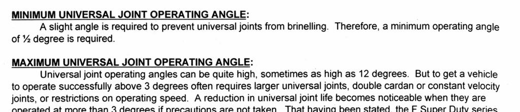
HA/HAS Series. NO: SUBJECT: Driveline Angularity Procedures DATE: March, 1999 REVISION: C CONTENTS ITEM SUBJECT PAGE
 HA/HAS Series NO: SUBJECT: Driveline Angularity Procedures DATE: March, 1999 REVISION: C CONTENTS ITEM SUBJECT PAGE 1 Introduction EDGE... 2 2 Important Safety Notice... 3 3 Frame Slope... 4 4 Axle/Suspension
INSTALLATION INSTRUCTIONS 88029
 INSTALLATION INSTRUCTIONS 88029 FOR SUSPENSION SYSTEMS RS6503: JEEP WRANGLER (TJ) READ ALL INSTRUCTIONS THOROUGHLY FROM START TO FINISH BEFORE BEGINNING INSTALLATION REV F IMPORTANT NOTES! WARNING: This
PERFORMANCE SUSPENSION PARTS
 PERFORMANCE SUSPENSION PARTS Introduction Air Lift Performance The purpose of this publication is to assist with the installation, maintenance and troubleshooting of this Audi A6 C5 Performance kit. It
Please read these instructions completely before proceeding with installation. Read all maintenance guidelines on page 7 before operating the vehicle.
 MN-643 (02511) ECR 5461 Kit No. 39205 Please read these instructions completely before proceeding with installation Item P/N Description Quantity A 26391 Driver-Side Beam Assembly 1 B 26414 Passenger-Side
2010+ Victory Cross Country / Cross Roads Installation Guide Nov 2014
 2010+ Victory Cross Country / Cross Roads Installation Guide Nov 2014 125 Industrial Drive Spearfish, SD 57783 Toll Free 888.3WHEELS w w w. l e h m a n t r i k e s. c o m UNDERSTANDING SAFETY LABELS &
kelderman air ride The difference in the ride is like night and day Improves the ride of the truck Automatic leveling is available
 Air Ride Conversion System Installation Instructions 800 334-6150 www.keldermanairride.com The difference in the ride is like night and day Inside this manual: 2003 & Newer Dodge 2-bag Rear System Tools
1988 Chevrolet Pickup V SUSPENSION - FRONT (4WD)' 'Front Suspension - "V" Series 1988 SUSPENSION - FRONT (4WD) Front Suspension - "V" Series
' 'Front Suspension - V Series 1988 SUSPENSION - FRONT (4WD) Front Suspension - V Series") 1988 SUSPENSION - FRONT (4WD) Front Suspension - "V" Series DESCRIPTION NOTE: Vehicle serial numbers used in this article has been abbreviated for common reference to Chevrolet and GMC models. Chevrolet
1988 SUSPENSION - FRONT (4WD) Front Suspension - "V" Series DESCRIPTION NOTE: Vehicle serial numbers used in this article has been abbreviated for common reference to Chevrolet and GMC models. Chevrolet
4 & 6 4-Link Suspension Systems. Ford Super Duty 4WD Part#: ,
 Part#: 013013, 013014 4 & 6 4-Link Suspension Systems Ford Super Duty 4WD 2011-2016 Rev. 051817 491 W. Garfield Ave., Coldwater, MI 49036. Phone: 517-279-2135 E-mail: tech-bds@sporttruckusainc.com Read
Robo-Assist Accessory
 Robo-Assist Accessory Kit 85607617 For use with BaseLine by COATS Tire Changers This is a supplement to your operating manual and covers the installation and use of the Robo-Assist accessory. If you do
JL Wrangler/Sahara/Sport
 IF your ReadyLIFT product has a damaged or missing part, please contact customer service directly and a new replacement part will be sent to you immediately. For warranty issues, please return to the place
INSTALLATION INSTRUCTION 88581
 INSTALLATION INSTRUCTION 88581 FOR RANCHO SUSPENSION SYSTEM RS6581B: DODGE RAM READ ALL INSTRUCTIONS THOROUGHLY FROM START TO FINISH BEFORE BEGINNING INSTALLATION Rev C IMPORTANT NOTES! WARNING: This suspension
Representative vehicle image
 Installation Guide Kit 57589 Dodge/RAM Heavy Duty Representative vehicle image For maximum effectiveness and safety, please read these instructions completely before proceeding with installation. Failure
(877) MON-FRI 7AM-5PM PST OR WEBSITE: ReadyLIFT.COM **Please retain this document in your vehicle at all times**
 MON-FRI 7AM-5PM PST OR WEBSITE: ReadyLIFT.COM **Please retain this document in your vehicle at all times**") IF YOUR ReadyLIFT PRODUCT IS MISSING A PART OR HAS A DAMAGED PART, PLEASE CONTACT CUSTOMER SERVICE DIRECTLY. A NEW REPLACEMENT PART WILL BE SENT TO YOU IMMEDIATELY (877)759-9991 MON-FRI 7AM-5PM PST OR
IF YOUR ReadyLIFT PRODUCT IS MISSING A PART OR HAS A DAMAGED PART, PLEASE CONTACT CUSTOMER SERVICE DIRECTLY. A NEW REPLACEMENT PART WILL BE SENT TO YOU IMMEDIATELY (877)759-9991 MON-FRI 7AM-5PM PST OR
Super Duty Front Air Bag Installation Instructions
 2005-2010 Super Duty Front Air Bag Installation Instructions Congratulations! You have just purchased the best engineered, highest quality front air suspension kit available on the market for your 2005-2010
»Product» Safety Warning
 D1401 Installation Instructions 2013 Ram 3500, 2014 Ram 2500 4.5" Radius Arm Suspension Lift Read and understand all instructions and warnings prior to installation of product and operation of vehicle.
Installation Instructions
 Part # 500399-00 Up Camaro Level 3 Shockwave System Front Components: 30 Front ShockWave Strut Recommended Tools Rear Components: 505 Rear ShockWave Miscellaneous Components: 303000 3 Gallon AirPod Compressor
INSTALLATION INSTRUCTIONS Auto Level Compressor Kit IMPORTANT NOTES
 INSTALLATION INSTRUCTIONS 4880 Auto Level Compressor Kit Thank you for purchasing a quality Hellwig Product. PLEASE READ THIS INSTRUCTION SHEET COMPLETELY BEFORE STARTING YOUR INSTALLATION IMPORTANT NOTES
Suspension System RS6582B
 Suspension System RS6582B Tahoe/Yukon READ ALL INSTRUCTIONS THOROUGHLY FROM START TO FINISH BEFORE BEGINNING INSTALLATION IMPORTANT NOTES! WARNING: This suspension system will enhance the off-road performance
MS2200, MS2500, and MS3000 Suspension Installation Manual ON/OFF HIGHWAY SUSPENSION SYSTEM
 MS22, MS25, and MS3 Suspension Installation Manual ON/OFF HIGHWAY SUSPENSION SYSTEM 972.547.62 8.445.736 FAX: 972.542.97 725 E. UNIVERSITY ST. McKINNEY, TEXAS 7569 www.watsonsuspensions.com Watson & Chalin
INSTALLATION INSTRUCTIONS Air Spring Kit Dodge WD IMPORTANT NOTES
 INSTALLATION INSTRUCTIONS 6211 Air Spring Kit 2003+ Dodge 1500 4WD Thank you for purchasing a quality Hellwig Product. PLEASE READ THIS INSTRUCTION SHEET COMPLETELY BEFORE STARTING YOUR INSTALLATION IMPORTANT
INSTALLATION INSTRUCTIONS
 INSTALLATION INSTRUCTIONS ----1075 North Ave. Sanger, CA 93657-3539 toll free: 800-445-3767 web: www.belltechcorp.com---- 6420 SHACKLE & HANGER KIT FORD F-350 Congratulations! You were selective enough
Kits Installation Guide. Dodge/RAM WD and 4WD
 S E R I E S TM Installation Guide Dodge/RAM 1500 2WD and 4WD Kits 57370 88370 89370 For maximum effectiveness and safety, please read these instructions completely before proceeding with installation.
Kit Chevrolet/GMC Heavy Duty. Installation Guide
 Installation Guide Kit 57538 Chevrolet/GMC Heavy Duty Representative vehicle image MN-1034 (021810) ECR 9155 For maximum effectiveness and safety, please read these instructions completely before proceeding
READ AND UNDERSTAND ALL INSTRUCTIONS AND WARNINGS PRIOR TO INSTALLATION OF SYSTEM AND OPERATION OF VEHICLE.
 #021700, 021701 7 Suspension System 2000-2004 Chevy/GMC 1500 2wd Extended Cab w/ Front Coil Springs READ AND UNDERSTAND ALL INSTRUCTIONS AND WARNINGS PRIOR TO INSTALLATION OF SYSTEM AND OPERATION OF VEHICLE.
Please read these instructions completely before proceeding with the installation.
 Fits Multi-Leaf Steel Spring Models Only. P/N 59111 This kit is for a 2" drop Please read these instructions completely before proceeding with the installation. by MN-346 (03006) ECN3100 Nylon Nut Upper
Detroit Speed, Inc. Detroit Speed Control Arm and Spindle Kit A-Body P/N: &
 Detroit Speed, Inc. Detroit Speed Control Arm and Spindle Kit 1964-72 A-Body P/N: 030104 & 030105 The Detroit Speed A-Body front suspension kit is a bolt-on package that addresses the shortcomings of the
Installation Instructions
 IF YOUR ReadyLIFT OFF ROAD SUSPENSION PRODUCT IS MISSING A PART OR HAS A DAMAGED PART, PLEASE CONTACT CUSTOMER SERVICE DIRECTLY. A NEW REPLACEMENT PART WILL BE SENT TO YOU IMMEDIATELY (800)549-4620 MON-FRI
Ford E-450 Kit No Please read these instructions completely before proceeding with installation
 MN-633 (12704) ECR 6107 Ford E-450 Kit No. 39217 Please read these instructions completely before proceeding with installation Failure to read these instructions can result in mis-installation Introduction
Part # Lincoln Level 2 Air Suspension Package
 350 S. St. Charles St. Jasper, In. 47546 Ph. 812.482.2932 Fax 812.634.6632 www.ridetech.com Part # 12060299 64-69 Lincoln Level 2 Air Suspension Package Front Components: 1 12060999 CoolRide Kit 1 12060601
C-4500 Kit No The Choice of the Professional Installer
 MN-585 (04503) ECR 5047 by C-4500 Kit No. 39023 Please read these instructions completely before proceeding with installation Failure to read these instructions can result in mis-installation Vehicle Requirements...
5.5 Gas & 6 Diesel Radius Arm Suspension System. Dodge Ram WD Pickup Dodge Ram WD Pickup
 Part#: 012610 5.5 Gas & 6 Diesel Radius Arm Suspension System Dodge Ram 3500 4WD Pickup 2013-17 Dodge Ram 2500 4WD Pickup 2014-17 491 W. Garfield Ave., Coldwater, MI 49036. Phone: 517-279-2135 Web: www.bds-suspension.com.
I. Assembling the Air Spring
 B F H G D FRONT I Assembling the Air Spring 1 Install 90 degree air swivel fitting (D) to the top of the bellow This fitting is precoated with sealant Using an open-end wrench, tighten 1 and 1 /2 turns
Air Lift. Kit Ford Mustang SN95 PERFORMANCE INSTALLATION GUIDE. Rear Application
 Air Lift PERFORMANCE Kit 78619 Ford Mustang SN95 Rear Application INSTALLATION GUIDE PERFORMANCE SUSPENSION PARTS For maximum effectiveness and safety, please read these instructions completely before
FAX
 559-734-7451 800-367-5480 FAX 559-734-7460 INSTALLATION INSTRUCTIONS 6091 Air Suspension Kit (pat. pending) 1999-2006 Tahoe, Suburban, Avalanche, Yukon Thank you for purchasing a quality Hellwig Product.
SUSPENSION 2-1 SUSPENSION TABLE OF CONTENTS
 XJ SUSPENSION 2-1 SUSPENSION TABLE OF CONTENTS page ALIGNMENT... 1 FRONT SUSPENSION... 7 page REAR SUSPENSION... 16 ALIGNMENT TABLE OF CONTENTS page AND WHEEL ALIGNMENT...1 DIAGNOSIS AND TESTING SUSPENSION
Installation Instructions , ,
 IF YOUR ReadyLIFT OFF ROAD SUSPENSION PRODUCT IS MISSING A PART OR HAS A DAMAGED PART, PLEASE CONTACT CUSTOMER SERVICE DIRECTLY. A NEW REPLACEMENT PART WILL BE SENT TO YOU IMMEDIATELY (800)549-4620 MON-FRI
M H F150 4X4 Rear Lowering Kit
 READ INSTRUCTIONS COMPLETELY THROUGH BEFORE STARTING. IT IS RECOMMENDED THAT INSTALLATION BE DONE BY A QUALIFIED MECHANIC. REPLACE ALL STOCK PARTS THAT ARE DAMAGED OR WORN. ALWAYS WEAR EYE PROTECTION.
SCION tc LOWERING SPRINGS Preparation
 Preparation Part Number: PTR11-21100 PTR11-21100-50 Kit Contents Item # Quantity Reqd. Description 1 2 Front Spring 2 2 Rear Spring 3 2 Locking Nut 4 2 Spring Bumper, Front 5 1 Instruction Form Hardware
C-10 Rear 4Link
 Part # 11367199-1973-1987 C10 Rear 4Link Recommended Tools 1973-1987 C-10 Rear 4Link Installation Table of contents Page 2... Included Components Page 3... Hardware List & Getting Started Page 4... Disassembly
(877) MON-FRI 7AM-5PM PST OR WEBSITE: ReadyLIFT.COM **Please retain this document in your vehicle at all times**
 MON-FRI 7AM-5PM PST OR WEBSITE: ReadyLIFT.COM **Please retain this document in your vehicle at all times**") IF YOUR ReadyLIFT PRODUCT IS MISSING A PART OR HAS A DAMAGED PART, PLEASE CONTACT CUSTOMER SERVICE DIRECTLY. A NEW REPLACEMENT PART WILL BE SENT TO YOU IMMEDIATELY (877)759-9991 MON-FRI 7AM-5PM PST OR
IF YOUR ReadyLIFT PRODUCT IS MISSING A PART OR HAS A DAMAGED PART, PLEASE CONTACT CUSTOMER SERVICE DIRECTLY. A NEW REPLACEMENT PART WILL BE SENT TO YOU IMMEDIATELY (877)759-9991 MON-FRI 7AM-5PM PST OR
2007 AND UP GM 4 LIFT 2WD/4WD TRUCK/SUV
 IF your ReadyLIFT product has a damaged or missing part, please contact customer service directly. For warranty issues please return to the place of installation and contact ReadyLIFT. A NEW REPLACEMENT
Kits and Single Gauge Analog Compressor Systems
 Kits 25850 and 25854 Single Gauge Analog Compressor Systems Kit #25850 with standard duty compressor Kit #25854 with heavy duty compressor MN-750 (061202) ECR 7259 INSTALLATION GUIDE For maximum effectiveness
HP10207 KIT. Ram WD*
 HP10207 KIT Ram 1500 4WD* (For 2WD call customer service 800.663.0096 for assistance) * See application guide for proper fitment. Use the most advanced air springs on the market to eliminate your vehicle
»Product» Safety Warning
 D1402 Installation Instructions 2013-14 Ram 3500, 2014 Ram 2500 4.5" Replacement Radius Arm Suspension Lift Read and understand all instructions and warnings prior to installation of product and operation
»Product» Safety Warning
 J1457, J1458 Installation Instructions 1984-2001 Jeep Cherokee XJ 4.5 Suspension Lift Read and understand all instructions and warnings prior to installation of product and operation of vehicle. Zone Offroad
CHEVY / GMC 1500HD / 2500HD 2WD 8 LUG 7 BASIC KIT
 85101 2000-2010 CHEVY / GMC 1500HD / 2500HD 2WD 8 LUG 7 BASIC KIT C8510-4 MAIN BOX KIT W/ HARDWARE 1) FRONT X MEMBER 1) REAR X MEMBER 2) TORSION BAR DROPS 1) LEFT BUMP STOP 1) RIGHT BUMP STOP 2) SWAY BAR