Independent Front Suspension
|
|
|
- Martha Webster
- 6 years ago
- Views:
Transcription
1 Independent Front Suspension Technical Training
2 Contents Why Independent? Tuthill Models Features and Benefits Description Special Tools Regular Maintenance Troubleshooting Available Kits Contacting Tuthill 2
3 Why Independent? Solid-Axle I-Beam Left and right wheels connected Impact on one wheel effects the other wheel Impact on one wheel effects steering, bump steer Camber not (easily) adjusted Camber does not change during cornering, no assist Independent Front Suspension Left and rights not connected Impact on one wheel does not effect the other wheel Impact on one wheel does not effect steering Camber is adjustable Camber changes during corning to assist road holding 3
4 Tuthill Models SUSPENSION MODEL GVWR (LBS) WHEEL MOUNT WHEEL CUT BRAKE SWAY BAR IN CURRENT PRODUCTION IFS1050-HP 10,500 Hub Pilot 50 15x4 Drum IFS1050S 10,500 Hub Pilot 55 15x4 Drum IFS1050S-SB 10,500 Hub Pilot 55 15x4 Drum Yes IFS1200-HP 12,000 Hub Pilot 45 15x4 Drum IFS1200-SP 12,000 Stud Pilot 45 15x4 Drum IFS1200S-SB 12,000 Hub Pilot 45 15x4 Drum Yes IFS1200S2 12,000 Hub Pilot 50 15x4 Drum IFS1200S2-SB 12,000 Hub Pilot 50 15x4 Drum Yes IFS1260S 12,600 Hub Pilot 57 * 15x4 Drum Yes IFS1260S-SB 12,600 Hub Pilot 57 * 15x4 Drum Yes Yes * 57 for Aluminum Rims only. Steel Rims limited to 55 Wheel Cut. 4
5 Tuthill Models SUSPENSION MODEL GVWR (LBS) WHEEL MOUNT WHEEL CUT BRAKE SWAY BAR IN CURRENT PRODUCTION IFS1320-HP 13,200 Hub Pilot x5 Drum IFS1320-SP 13,200 Stud Pilot x5 Drum IFS1370-HP 13,700 Hub Pilot x5 Drum IFS1370-SP 13,700 Stud Pilot x5 Drum IFS1370S-SB 13,700 Hub Pilot x5 Drum Yes IFS1460-HP 14,600 Hub Pilot x5 Drum IFS1460S 14,600 Hub Pilot x5 Drum Yes IFS1460S-SB 14,600 Hub Pilot x5 Drum Yes Yes IFS1460S-DSB 14,600 Hub Pilot 55 Air Disc Yes Yes IFS1660S 16,600 Hub Pilot 55 Air Disc Yes IFS1660S-SB 16,600 Hub Pilot 55 Air Disc Yes Yes 5
6 Features and Benefits Industry leading wheel cut (57 on IFS1260) Full range of products Bilstein shock absorbers for optimized ride and handling Both sway bar and non-sway bar models available Automotive style Short-Long-Arm suspension design Lubed for life ball joints Unitized construction Built in brake anti-dive 6

7 Family of Units IFS1050 IFS1260 IFS1200/1320/1370 IFS1460/1660 7
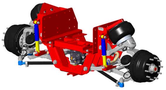
8 Brakes Steering Knuckle IFS1050 Family Cradle Air Spring Upper Control Arm Hub and Drum Tie Rod Gearbox Sway Bar Serial Tag Shock Lower Control Arm 8
9 IFS1200/IFS1200S2/IFS1320/ IFS1370 Family Upper Control Arm Hub and Drum Assembly Cradle Shock Knuckle Air Spring Steering Stabilizer Relay Rod Serial Tag Bell Crank Tie Rod 9 Brake Lower Control Arm
10 Hub and Drum Assembly Air Spring IFS1260 Family Cradle Serial Tag Upper Control Arm Knuckle Shock Tie Rod Gearbox Sway Bar Lower Control Arm 10 Brake
11 Hub and Drum Assembly Tie Rod IFS1460/1660 Family Cradle Sway Bar (Behind Unit) Air Spring Lower Air Spring Mount Upper Control Arm Brake Relay Rod Serial Tag Crank Arm Link Rod Lower Control Arm Sway Bar Mount 11
12 Steering Arm IFS1460/1660 Family Tie Rod Sway Bar Carrier Knuckle Carrier Pin Bell Crank Idler Arm 12 Lower Shock Mount
13 Cap IFS1460/1660 Family Kingpin Shim Draw Key (Upper) Bearing Seal Draw Key (Lower) 13

14 IFS1460/1660 Family Disc Brakes 14
15 Special Tools Service Manual(s) Dial Indicators C-Clamps Pry Bar Ruler or Tape Measure Torque Wrench and Sockets Voltmeter (AC Volts) 15
 Recommend Snap-On Bar-Type CJ")


16 Special Tools Ball Joint Remover (Do not use pickle forks ) Recommend Snap-On Bar-Type CJ Pullers 4-3/8 Jaws 3/4-16x4-1/4 Pressure Screw 3-1/2 to 6 Yoke Ball Joint Wrenches 40mm Ball Joint Special Tool 50mm Ball Joint Special Tool 65mm Ball Joint Special Tool 40mm Special Tool 65mm Special Tool 16
17 Regular Maintenance Topics in Service Manuals: Part Identification/Description Maintenance Record Maintenance Schedule Lubrication Schedule Inspection Procedures Lubrication Procedures Trouble Shooting and Repair Adjustments Torque Specifications 17
18 Regular Maintenance Lubricant Specification and Intervals COMPONENT SERVICE INTERVAL CHANGE INTERVAL LUBRICANT SPECIFICATION Ball Studs on Ends of Tie Rods, Relay Rod, Drag Link Which ever comes first: 50,000 miles (80,000 kilometers) or once a year. N/A Multi-Purpose Chassis Grease NLGI Grade 1 or 2 Lithium Base Bell Crank and Idler Arm Which ever comes first: 50,000 miles (80,000 kilometers) or once a year. N/A Multi-Purpose Chassis Grease NLGI Grade 1 or 2 Lithium Base Brake S-Cam Tube and Automatic Slack Adjuster 1 Which ever comes first: Brakes relined. 50,000 miles (80,000 kilometers) or once a year. N/A Multi-Purpose Chassis Grease NLGI Grade 1 or 2 Lithium Base Wheel End 1000 miles (1600 kilometers) Check fluid level. Which ever comes first: Seals replaced, brakes relined, 100,000 miles (160,000 km), or once a year. Gear Oil SAE 80W/90 or equivalent 1 Moly-disulfide type grease is not recommended since it may lower friction capabilities in the adjusting clutch parts of the automatic slack adjuster. 18
19 Troubleshooting and Repair Part Identification/Description Service Parts Troubleshooting Charts Inspection Adjustments and Alignment Repair Torque Specifications 19
20 Troubleshooting and Repair Suspension System--General SYMPTOMS POSSIBLE CAUSES REMEDIES Tires wear out quickly or have uneven tire tread wear. 1) Tires have incorrect pressure. 1) Put specified air pressure in tires. 2) Tires out of balance. 2) Balance or replace tires. 3) Incorrect toe-in setting. 3) Adjust toe-in to specified setting. 4) Incorrect ride height. 4) Adjust ride height to specified setting. 5) Incorrect rear axle alignment. 5) Align rear axle to specified thrust angle. 6) Incorrect steering arm geometry. 6) Adjust tie rod lengths as required. 7) Improper (mismatched) tires and wheels. 7) Install correct tire and wheel combination. 20
21 Troubleshooting and Repair Vehicle pulls to one side without the brakes applied Spartan has an inspection list. This will include: Check Rear Axle Thrust Angle Adjust the rear axle alignment per Spartan or ReycoGranning procedure. Front Suspension Toe Settings Adjust the toe-in per the alignment procedure Overall Toe-In of 1/8 total recommended Steering Gear is on Center Ride Height of Front and Rear Suspensions Tire Pressure If problem persists, Contact Spartan 21
22 Alignment Industry standard alignment equipment is recommended Both Josam and Protrak alignment equipment have been used by ReycoGranning and Spartan Calibration of alignment equipment is Critical Toe is adjustable on all units IFS1200/1320/1370: use relay rod IFS1050/1260/1460/1660: use outer tie rods All units equipped with Eccentrics IFS1200/1320/1370: Upper control arms only IFS1460/1660: Lower control arms only IFS1050/1260: Both upper and lower control arms 22
23 Alignment: Caster and Camber Adjust using the Eccentrics The set screw is orientated opposite to the control arm pivot bolt Set screw closest to frame, the control arm pivot bushing is furthest from the frame Set screw furthest from the frame, the control arm pivot bushing is closest to the frame To Adjust Camber: Move both bushing sets of eccentrics on the control arm the same direction To Adjust Caster: Move one bushing set opposite of the other bushing set on the control arm Rotate set screw away from frame Moves pivot bolt towards frame Frame Rails 23
24 Alignment: Caster Upper Control Arm King Pin Angle (or through ball joint centers) More Caster Less Caster Tire Lower Control Arm Forward UCA pivot move back -and/or- LCA pivot move forward UCA pivot move forward -and/or- LCA pivot move back 24
25 Alignment: Camber UCA in UCA out LCA out LCA in Less Camber (Red shows negative camber) More Camber 25
26 Alignment: Caster and Camber Spec s Model Left Right Left Right Camber Camber Caster Caster IFS /4 +1/4 2-1/4 2-1/4 ±1/4 ±1/4 ± 1/2 ± 1/2 IFS1200/1200S2 +1/4 +1/ /2 ±1/4 ±1/4 ± 1/2 ± 1/2 IFS1320/ /4 +1/ /2 ±1/4 ±1/4 ± 1/2 ± 1/2 IFS /4 +1/4 3 3 ±1/4 ±1/4 ± 1/2 ± 1/2 IFS1460/ /4 +1/4 3 3 ±1/4 ±1/4 ± 1/2 ± 1/2 26
27 Alignment: Toe (IFS1050)
28 Alignment: Toe (IFS1260) Tie Rods 0 28
29 Alignment: Toe (IFS1050/1260) Center the gearbox Loosen all four tie rod clamps Adjust the length of each tie rod until the toe-in on each side is 1/16 ± 1/32 and the overall toe-in is 1/8 ± 1/16. Measure the length of each tie rod and adjust until the tie rods measure within 1/16 of each other. Orient the tie rod clamps as shown and retighten. 29
30 Alignment: Toe (IFS1200/1320/1370) Relay Rod Outer Tie Rods Stabilizer Shock U-Bolts 30
31 Alignment: Toe (IFS1200/1320/1370) Measure Outer Tie Rods: Lengths should be within 1/8 of each other. If not, adjust length to 20-3/4 (center of grease fitting to grease fitting). Loosen Stabilizer Shock U-Bolts Loosen Relay Rod End Nuts Nuts with notches in points are left handed threads. Rotate Relay Rod Toe each side: 1/16 ± 1/32 Overall Toe: 1/8 ± 1/16 31
32 Alignment: Toe (IFS1460/1660) Tie Rods (note clamp orientation) 32
33 Alignment: Toe (IFS1460/1660) Loosen all four tie rod clamps Adjust the length of each tie rod until the toe-in on each side is 1/16 ± 1/32 and the overall toe-in is 1/8 ± 1/16. Measure the length of each tie rod and adjust until the tie rods measure within 1/16 of each other. Orient the tie rod clamps as shown and retighten. 33
34 Troubleshooting and Repair Clunking noise during turns Loose components. Check torque on all fasteners, especially bell crank and idler arm mounts, upper and lower control arm mounts, and steering gear box mounts. Check torque on all steering tie rod components. Excessive axial end play in bell crank and/or idler arm (IFS1200/1370 only) Granning kit 9898 provides shims and instructions. 34
35 Troubleshooting and Repair Checking for Bell Crank/Idler Arm end play, per p/n
36 Troubleshooting and Repair Vehicle ride is too soft This is subjective. Motor home manufacturers and Spartan Motors have selected the current valving of the shock absorber. IFS1200 units can use IFS1320 shock absorbers. This is not an warrantable item. Vehicle pulls to one side with the brakes applied Uneven brake adjustment side to side. Adjust slacks per Haldex guidelines. Brake drum out of round. Re-machine brake drums as required. Brake drums can not be relined. See Vehicle pulls to one side without the brakes applied. 36
37 Troubleshooting and Repair Steering Adjustments For readjusting the Steering Gear Box Poppet valves refer to TRW s TAS Steering Gear Service Manual. Do not adjust the turn angle greater than maximum noted earlier Unequal toe-in side to side or out-of-center steering gear can result in unequal turn angles. Recommended to set Toe-In through the use of the Relay Rod Check that the outer Tie-Rods are of equal length. Check that the steering gear is centered with equal toe-in side to side. Do not adjust the length of the Drag Link or Tie Rods to center the steering wheel. 37
38 Troubleshooting and Repair Vehicle front end will not remain aired up overnight Air leaks. Height Control Valves. Contact Spartan for possible resolutions. 38
39 Troubleshooting and Repair Broken shock absorber mounts (IFS1200/1370) Earlier units used stud style mounts. Kit 9902 converts to bolt style mounts Early Stud Style Mounts Newer Bolt Style Mounts 39
40 Available Kits Eccentric Adapter Kit: 9890 (IFS1200/1370) (For one side) Bell Crank/Idler Arm Shim Kit: 9898 (IFS1200/1320/1370) K (IFS1460/1660) Shock Absorber Mount Retrofit Kit: 9902 (IFS1200/1370) Brake Shoe and Lining Kits (ES420) K (IFS1200/1050/1260) Dana ES 15x4 K (IFS1200 older) Dana XL15x4 K (IFS1320/1370) Dana ES 16.5x5 K (IFS1460) Dana ES 16.6x5 IFS1200/1320/1370 Idler Arm Kit: K IFS1200/1320/1370 Bell Crank Kit: K (not for IFS1200S2) Cradle Gusset Kits: K (IFS1320/1370) K (IFS1200) Carrier Bolt Kit (IFS1460): K
41 Contacting Tuthill For all Parts Inquiries, Warranty, or Technical Assistance: Call: (Customer Service) Fax: (Customer Service) Website: Mail: Tuthill P.O. Box 600 Brookston, IN
42 Contacting Spartan For all Parts Inquiries, Warranty, or Technical Assistance: Call: (Motorhome Support) (Parts) Website: Mail: Spartan Chassis 1165 Reynolds Rd. Charlotte, MI
IFS1660S3/1700S3/1800S3/2000S3
 Motorhome Suspensions Owner s Manual IFS1660S3/1700S3/1800S3/2000S3 Independent Front Suspension Reyco Granning Suspensions 1205 Industrial Park Drive Mount Vernon, MO 65712 Phone: 417-466-2178 Fax: 417-466-3964
IFS1700S. Owner s Manual. Motorhome Suspensions. Maintenance Instructions Service Parts
 Motorhome Suspensions IFS1700S Owner s Manual Independent Front Suspension Maintenance Instructions Service Parts Document #: D711987 Revision: C Revision Date: 9/14 1-800-753-0050 w w w. r e y c o g r
Motorhome Suspensions. Owner s Manual. Maintenance Instructions Service Parts. Document #: D Revision: A Revision Date: 3/16
 Motorhome Suspensions Owner s Manual IFS1000-WF Independent Front Suspension Maintenance Instructions Service Parts Document #: D712230 Revision: A Revision Date: 3/16 1-800-753-0050 w w w. r e y c o g
FRONT SUSPENSION GROUP CONTENTS GENERAL INFORMATION FASTENER TIGHTENING SPECIFICATIONS GENERAL SPECIFICATIONS...
 33-1 GROUP 33 FRONT SUSPENSION CONTENTS GENERAL INFORMATION 33-2 FASTENER TIGHTENING SPECIFICATIONS 33-2 GENERAL SPECIFICATIONS 33-3 SERVICE SPECIFICATIONS 33-3 DIAGNOSIS 33-4 INTRODUCTION TO DIAGNOSIS
FRONT SUSPENSION GROUP CONTENTS GENERAL INFORMATION SPECIFICATIONS STRUT ASSEMBLY FRONT SUSPENSION DIAGNOSIS.
 33-1 GROUP 33 FRONT SUSPENSION CONTENTS GENERAL INFORMATION 33-2 SPECIFICATIONS 33-3 FASTENER TIGHTENING SPECIFICATIONS 33-3 GENERAL SPECIFICATIONS 33-3 SERVICE SPECIFICATIONS 33-3 LUBRICANT 33-3 DIAGNOSIS
IFS2400S-FT/IFS2000S-FT. Fire Apparatus Suspensions. Owner s Manual. Maintenance Instructions Service Parts
 Fire Apparatus Suspensions IFS2400S-FT/IFS2000S-FT Independent Front Suspension Owner s Manual Maintenance Instructions Service Parts Document #: D710023 Revision: E Revision Date: 10/14 1-800-753-0050
FRONT SUSPENSION GROUP CONTENTS GENERAL INFORMATION ON-VEHICLE SERVICE FASTENER TIGHTENING SPECIFICATIONS...
 33-1 GROUP 33 FRONT SUSPENSION CONTENTS GENERAL INFORMATION 33-2 FASTENER TIGHTENING SPECIFICATIONS 33-2 GENERAL SPECIFICATIONS 33-3 SERVICE SPECIFICATIONS 33-3 LUBRICANTS 33-3 DIAGNOSIS 33-4 INTRODUCTION
GROUP 33A 33A-1 CONTENTS GENERAL DESCRIPTION... 33A-2 FRONT SUSPENSION DIAGNOSIS. 33A-3 LOWER ARM... 33A-13 SPECIAL TOOLS... 33A-5
 33A-1 GROUP 33A CONTENTS GENERAL DESCRIPTION 33A-2 DIAGNOSIS 33A-3 INTRODUCTION TO FRONT SUSPENSION DIAGNOSIS 33A-3 DIAGNOSIS TROUBLESHOOTING STRATEGY 33A-3 SYMPTOM CHART 33A-3 SYMPTOM PROCEDURES 33A-3
FRONT SUSPENSION GROUP 33A 33A-1 CONTENTS GENERAL DESCRIPTION... 33A-2 FRONT SUSPENSION DIAGNOSIS. 33A-3 LOWER ARM... 33A-13 SPECIAL TOOLS...
 33A-1 GROUP 33A FRONT SUSPENSION CONTENTS GENERAL DESCRIPTION......... 33A-2 DIAGNOSIS. 33A-3 INTRODUCTION TO DIAGNOSIS........................ 33A-3 DIAGNOSIS TROUBLESHOOTING STRATEGY...... 33A-3 SYMPTOM
SuperTrac. Axle. Service & Maintenance. Manual
 SuperTrac Axle Service & Maintenance Manual Table of Contents Page Exploded Views Section 1: General Information General Warnings Description of Axle Models Identifications Section 2: Installation Axle
SUSPENSION 2-1 SUSPENSION TABLE OF CONTENTS
 XJ SUSPENSION 2-1 SUSPENSION TABLE OF CONTENTS page ALIGNMENT... 1 FRONT SUSPENSION... 7 page REAR SUSPENSION... 16 ALIGNMENT TABLE OF CONTENTS page AND WHEEL ALIGNMENT...1 DIAGNOSIS AND TESTING SUSPENSION
SUSPENSION 2-1 SUSPENSION CONTENTS
 ZJ SUSPENSION 2-1 SUSPENSION CONTENTS page ALIGNMENT... 1 FRONT SUSPENSION... 6 page REAR SUSPENSION... 14 ALIGNMENT INDEX page GENERAL INFORMATION WHEEL ALIGNMENT... 1 DIAGNOSIS AND TESTING SUSPENSION
1988 Chevrolet Pickup V SUSPENSION - FRONT (4WD)' 'Front Suspension - "V" Series 1988 SUSPENSION - FRONT (4WD) Front Suspension - "V" Series
' 'Front Suspension - V Series 1988 SUSPENSION - FRONT (4WD) Front Suspension - V Series") 1988 SUSPENSION - FRONT (4WD) Front Suspension - "V" Series DESCRIPTION NOTE: Vehicle serial numbers used in this article has been abbreviated for common reference to Chevrolet and GMC models. Chevrolet
1988 SUSPENSION - FRONT (4WD) Front Suspension - "V" Series DESCRIPTION NOTE: Vehicle serial numbers used in this article has been abbreviated for common reference to Chevrolet and GMC models. Chevrolet
Refer to separate Installation Instructions for installation details.
 OWNER S GUIDE 8A000729 DuraLift 13.5 13,500 CAPACITY Link Mfg. Ltd. 223 15th St. N.E. Sioux Center, IA USA 51250-2120 www.linkmfg.com QUESTIONS? CALL CUSTOMER SERVICE 1-800-222-6283 DEALER / INSTALLER:
SECTION steering mechanism
 07-302.01/ 1 2011MR17 SECTION 07-302.01 GENERAL Description See Figure 1. The includes the steering wheel (1), the steering column, the miter box (3), the steering shafts (2 and 4), and the drag link (7).
TC Series Front Axle. TC Series Front Axle 010-1
 TC Series Front Axle Blue Bird Corporation assumes sole responsibility for ensuring that the information provided herein is accurate to the best of its knowledge at the time of printing. In keeping with
Return To Main Table of Contents GENERAL... 2 STRUT ASSEMBLY LOWER ARM STABILIZER BAR CENTER MEMBER WHEEL AND TIRE...
 FRONT SUSPENSION Return To Main Table of Contents GENERAL... 2 STRUT ASSEMBLY... 11 LOWER ARM... 13 STABILIZER BAR... 17 CENTER MEMBER... 19 WHEEL AND TIRE... 21 GENERAL GENERAL SPECIFICATIONS Suspension
REAR SUSPENSION GROUP CONTENTS GENERAL DESCRIPTION REAR SUSPENSION DIAGNOSIS LOWER ARM AND TOE CONTROL ARM ASSEMBLY...
 34-1 GROUP 34 CONTENTS GENERAL DESCRIPTION........... 34-2 DIAGNOSIS.... 34-2 INTRODUCTION....................... 34-2 TROUBLESHOOTING STRATEGY........ 34-2 SYMPTOM CHART..................... 34-3 SYMPTOM
SUSPENSION 2-1 SUSPENSION CONTENTS
 TJ SUSPENSION 2-1 SUSPENSION CONTENTS page ALIGNMENT... 1 FRONT SUSPENSION... 5 page REAR SUSPENSION... 12 ALIGNMENT INDEX page GENERAL INFORMATION WHEEL ALIGNMENT... 1 DIAGNOSIS AND TESTING SUSPENSION
SUSPENSION 2-1 SUSPENSION CONTENTS
 TJ SUSPENSION 2-1 SUSPENSION CONTENTS page ALIGNMENT... 1 FRONT SUSPENSION... 6 page REAR SUSPENSION... 13 ALIGNMENT INDEX page DESCRIPTION AND OPERATION WHEEL ALIGNMENT... 1 DIAGNOSIS AND TESTING SUSPENSION
OWNER S GUIDE 8A DURALIFT II 13,200 LB. CAPACITY. Link Mfg. Ltd th St. N.E. Sioux Center, IA USA
 OWNER S GUIDE 8A000715 DURALIFT II 13,200 LB. CAPACITY Link Mfg. Ltd. 223 15th St. N.E. Sioux Center, IA USA 51250-2120 www.linkmfg.com QUESTIONS? CALL CUSTOMER SERVICE 1-800-222-6283 DEALER / INSTALLER:
INSTALLATION INSTRUCTIONS GM Lower Control Arms P/N 52337, 52437, 52364, 52464, 52319, 52419, 52320, 52420, 52366, 52466, 52368, 52468
 INSTALLATION INSTRUCTIONS GM Lower Control Arms P/N 52337, 52437, 52364, 52464, 52319, 52419, 52320, 52420, 52366, 52466, 52368, 52468 TOOLS AND SUPPLIES REQUIRED Floor Jack Jack Stands Wrench Set Hex
Steering and Suspension
 The Steering and Suspension system is engineered to allow the vehicle to turn and absorb road irregularities. The suspension is comprised of springs, suspension arms or links and shock dampers. These components
SUSPENSION 2-1 SUSPENSION TABLE OF CONTENTS
 DN SUSPENSION 2-1 SUSPENSION TABLE OF CONTENTS page ALIGNMENT... 1 FRONT SUSPENSION - 4x2... 6 page FRONT SUSPENSION - 4x4... 14 REAR SUSPENSION... 23 ALIGNMENT TABLE OF CONTENTS page AND OPERATION WHEEL
REAR SUSPENSION GROUP CONTENTS GENERAL INFORMATION FASTENER TIGHTENING SPECIFICATIONS TRAILING ARM...
 34-1 GROUP 34 CONTENTS GENERAL INFORMATION 34-2 FASTENER TIGHTENING SPECIFICATIONS 34-4 GENERAL SPECIFICATIONS 34-4 SERVICE SPECIFICATIONS 34-5 LUBRICANTS 34-5 DIAGNOSIS 34-6 INTRODUCTION TO DIAGNOSIS
Spicer Steer Axles. Service Manual. AXSM0038 September 2013
 Spicer Steer Axles Service Manual AXSM008 September 0 Warnings and Cautions Warnings and Cautions The description and specifications contained in this service publication are current at the time of printing.
S-ABA Service Manual. Self-Setting Automatic Brake Adjusters
 S-ABA Service Manual Self-Setting Automatic Brake Adjusters Warning: Haldex strongly recommends routine visual checks be performed at EACH maintenance service interval. Foundation brake operational checks
DIAGNOSIS AND TESTING
 DIAGNOSIS AND TESTING SUSPENSION AND STEERING SYSTEM 2007 SUSPENSION Suspension - Nitro CONDITION POSSIBLE CAUSES CORRECTION FRONT END NOISE 1. Loose or worn wheel bearings. 1. Replace wheel bearings.
Premium wheel-end brake products
 Premium wheel-end brake products Spicer Automatic Slack Adjuster Service Manual Self Adjusting Brake Adjuster The description and specifications contained in this service publication are current at the
(800) MON-FRI 7AM-5PM PST OR WEBSITE: ReadyLIFT.COM **Please retain this document in your vehicle at all times**
 MON-FRI 7AM-5PM PST OR WEBSITE: ReadyLIFT.COM **Please retain this document in your vehicle at all times**") IF YOUR ReadyLIFT PRODUCT IS MISSING A OR HAS A DAM- AGED PART, PLEASE CONTACT CUSTOMER SERVICE DIRECTLY. For warranty issues please return to the place of installation and contact ReadyLIFT. A NEW REPLACEMENT
IF YOUR ReadyLIFT PRODUCT IS MISSING A OR HAS A DAM- AGED PART, PLEASE CONTACT CUSTOMER SERVICE DIRECTLY. For warranty issues please return to the place of installation and contact ReadyLIFT. A NEW REPLACEMENT
REAR SUSPENSION GROUP CONTENTS GENERAL DESCRIPTION TRAILING ARM REAR SUSPENSION DIAGNOSIS TOE CONTROL ARM...
 34-1 GROUP 34 CONTENTS GENERAL DESCRIPTION 34-2 DIAGNOSIS 34-3 INTRODUCTION TO DIAGNOSIS 34-3 DIAGNOSTIC TROUBLESHOOTING STRATEGY 34-3 SYMPTOM CHART 34-3 SYMPTOM PROCEDURES 34-3 SPECIAL TOOLS 34-5 ON-VEHICLE
BRAKE SYSTEM Return To Main Table of Contents
 BRAKE SYSTEM Return To Main Table of Contents GENERAL... 2 BRAKE PEDAL... 10 MASTER CYLINDER... 13 BRAKE BOOSTER... 16 BRAKE LINE... 18 PROPORTIONING VALVE... 19 FRONT DISC BRAKE... 20 REAR DRUM BRAKE...
REAR SUSPENSION GROUP CONTENTS GENERAL DESCRIPTION TRAILING ARM ASSEMBLY REAR SUSPENSION DIAGNOSIS
 34-1 GROUP 34 CONTENTS GENERAL DESCRIPTION......... 34-2 DIAGNOSIS.. 34-3 INTRODUCTION TO DIAGNOSIS........................ 34-3 DIAGNOSIS TROUBLESHOOTING STRATEGY...... 34-3 SYMPTOM CHART...................
Spicer Axles & Brakes
 Information Bulletin Bulletin Type: Parts / Service Information Spicer Axles & Brakes Topic: Dana Corporation Steer Knuckle Recall Identification and Repair Procedure Affected Models: Steer Axle Knuckle
AXLE ALIGNMENT ZF (40 FT)
") SECTION 04-000.10 04-000.10/ 1 2010DE06 GENERAL CONDITIONS See Figures 1 and 2 for the geometry of the frontand rear axles. Figure 3 represents the axis system of a Nova LFS 40-ft bus. Before performing
SECTION 04-000.10 04-000.10/ 1 2010DE06 GENERAL CONDITIONS See Figures 1 and 2 for the geometry of the frontand rear axles. Figure 3 represents the axis system of a Nova LFS 40-ft bus. Before performing
SECTION ZF FRONT AXLE
 04-101.01/ 1 2011JA14 SECTION 04-101.01 6 3 5 1 2 9 1. Upper radius rod 2. Lower radius rod 3. Caliper 4. BRAKE Disk 5. Pneumatic connector 6. Hub 7. steering knuckle 8. Grease Fitting 9. Pneumatic connector
FRONT SUSPENSION GROUP 2 FRONT SUSPENSION 2-1 CONTENTS SPECIFICATIONS VC-1, VC-2, VC-3 VY-1 TOOL LIST. Page
 GROUP 2 FRONT SUSPENSION CONTENTS Page Specifications 1 Tool List.... 1 Torque Reference 2 Preparation for Measuring Front End Alignment... 2 Front Suspension Height Adjustment 3 Front Suspension Alignment
Inspection and Verification, Ranger
 file://c:\tso\tsocache\vdtom_5368\svk~us~en~file=svk53a03.htm~gen~ref.htm Page 1 of 1 Section 05-03A: Wheel Hubs and Bearings, Front Wheels, 4- Wheel Drive DIAGNOSIS AND TESTING 1997 Ranger 4x4 with Dana
SUSPENSION 2-1 SUSPENSION CONTENTS
 DN SUSPENSION 2-1 SUSPENSION CONTENTS page ALIGNMENT... 1 FRONT SUSPENSION... 5 page REAR SUSPENSION... 13 ALIGNMENT INDEX page GENERAL INFORMATION WHEEL ALIGNMENT... 1 DIAGNOSIS AND TESTING PRE-ALIGNMENT
FRONT & REAR SUSPENSION SECTIONSU CONTENTS IDX. FRONT SUSPENSION...2 Precautions...2. REAR SUSPENSION...14 Precautions...14
 FRONT & REAR SUSPENSION SECTIONSU GI MA EM LC EC CONTENTS FE FRONT SUSPENSION...2 Precautions...2 PRECAUTIONS...2 Preparation...2 SPECIAL SERVICE TOOLS...2 COMMERCIAL SERVICE TOOLS...2 Noise, Vibration
Camber Angle. Wheel Alignment. Camber Split. Caster Angle. Caster and Ride Height. Toe Angle. AUMT Wheel Alignment
 AUMT 1316 - Wheel Alignment 11/15/11 Camber Angle Wheel Alignment Donald Jones Brookhaven College Camber Split Camber is the amount that the centerline of the wheel tilts away from true vertical when viewed
Multilink IRS Setup & Assembly Manual
 Art Morrison Enterprises Multilink IRS Setup & Assembly Manual 8/13/2018 Rev 6 Contents Introduction... 3 Toe Link Eccentric... 3 Powdercoating... 3 IRS Assembly Steps... 4 1. Backing plates/knuckles/hubs...
1984 Dodge W250 PICKUP
 1984 Dodge W250 PICKUP Submodel: Engine Type: V8 Liters: 5.2 Fuel Delivery: CARB Fuel: GAS Dana 44 MODELS THROUGH 1984 2. Raise and safely support the vehicle, then remove the wheel hub and bearings as
REAR AXLE GROUP CONTENTS GENERAL DESCRIPTION REAR AXLE DIAGNOSIS REAR AXLE HUB ASSEMBLY KNUCKLE...
 27-1 GROUP 27 CONTENTS GENERAL DESCRIPTION......... 27-2 DIAGNOSIS......... 27-2 INTRODUCTION TO DIAGNOSIS........................ 27-2 DIAGNOSTIC TROUBLESHOOTING STRATEGY...... 27-2 SYMPTOM CHART...................
SUSPENSION 2-1 SUSPENSION CONTENTS
 WJ SUSPENSION 2-1 SUSPENSION CONTENTS page ALIGNMENT... 1 FRONT SUSPENSION... 4 page REAR SUSPENSION... 15 ALIGNMENT INDEX page AND WHEEL ALIGNMENT... 1 SERVICE PROCEDURES PRE-ALIGNMENT... 2 AND WHEEL
(877) MON-FRI 7AM-5PM PST OR WEBSITE: ReadyLIFT.COM **Please retain this document in your vehicle at all times**
 MON-FRI 7AM-5PM PST OR WEBSITE: ReadyLIFT.COM **Please retain this document in your vehicle at all times**") IF YOUR ReadyLIFT PRODUCT IS MISSING A OR HAS A DAMAGED PART, PLEASE CONTACT CUSTOMER SERVICE DIRECTLY. For warranty issues please return to the place of installation and contact ReadyLIFT. A NEW REPLACEMENT
IF YOUR ReadyLIFT PRODUCT IS MISSING A OR HAS A DAMAGED PART, PLEASE CONTACT CUSTOMER SERVICE DIRECTLY. For warranty issues please return to the place of installation and contact ReadyLIFT. A NEW REPLACEMENT
Service Manual Truck and Trailer Applications. AA1 Automatic Brake Adjusters
 Service Manual Truck and Trailer Applications AA1 Automatic Brake Adjusters Table of Contents Operation... 1 Brake Adjuster Part Number and Build Date... 1 Steer Axle Applications... 2 Drive Axle Applications...
SUSPENSION - FRONT Infiniti G20 DESCRIPTION ADJUSTMENTS & INSPECTION SUSPENSION Front G20
 SUSPENSION - FRONT 1992 Infiniti G20 1991-92 SUSPENSION Front G20 DESCRIPTION G20 uses a 4-wheel independent multi-link suspension system. Transverse links are connected to bottom of steering knuckle.
FRONT & REAR SUSPENSION SECTIONSU CONTENTS IDX. FRONT SUSPENSION...2 Precautions...2
 FRONT & REAR SUSPENSION SECTIONSU GI MA EM LC EC CONTENTS FE...2 Precautions...2 PRECAUTIONS...2 Preparation...2 SPECIAL SERVICE TOOLS...2 COMMERCIAL SERVICE TOOLS...2 Noise, Vibration and Harshness (NVH)
FRONT SUSPENSION SECTION CONTENTS E SUSPENSION FSU-1 FSU
 E SUSPENSION A SECTION FRONT SUSPENSION B C D CONTENTS FSU PRECAUTIONS... 2 Precautions... 2 PREPARATION... 3 Special Service Tools... 3 Commercial Service Tools... 3 NOISE, VIBRATION, AND HARSHNESS (NVH)
2. MEASURE VEHICLE HEIGHT. (b) Measure the vehicle height. Measurement points: C: Ground clearance of front wheel center
 Measure the vehicle height. Measurement points: C: Ground clearance of front wheel center") ADJUSTMENT If the wheel alignment has been adjusted, and if suspension or underbody components have been removed/installed or replaced, be sure to perform the following initialization procedure in order
ADJUSTMENT If the wheel alignment has been adjusted, and if suspension or underbody components have been removed/installed or replaced, be sure to perform the following initialization procedure in order
FRONT & REAR SUSPENSION SECTIONSU CONTENTS IDX. FRONT SUSPENSION...2 Precautions...2. Service Data and Specifications (SDS)...21
...21") FRONT & REAR SUSPENSION SECTIONSU GI MA EM LC EC CONTENTS FE...2 Precautions...2 PRECAUTIONS...2 Preparation...2 SPECIAL SERVICE TOOLS...2 COMMERCIAL SERVICE TOOLS...2 Noise, Vibration and Harshness (NVH)
FRONT & REAR SUSPENSION SECTIONSU GI MA EM LC EC CONTENTS FE...2 Precautions...2 PRECAUTIONS...2 Preparation...2 SPECIAL SERVICE TOOLS...2 COMMERCIAL SERVICE TOOLS...2 Noise, Vibration and Harshness (NVH)
FRONT SUSPENSION SECTION FSU CONTENTS E SUSPENSION FSU-1 FSU
 E SUSPENSION SECTION FSU A FRONT SUSPENSION B C D CONTENTS FSU PRECAUTIONS... 2 Precautions... 2 PREPARATION... 3 Special Service Tools... 3 Commercial Service Tools... 3 NOISE, VIBRATION, AND HARSHNESS
FRONT & REAR SUSPENSION SECTIONSU CONTENTS IDX. FRONT SUSPENSION...2 Precautions...2
 FRONT & REAR SUSPENSION SECTIONSU GI MA EM LC CONTENTS EC FE FRONT SUSPENSION...2 Precautions...2 PRECAUTIONS...2 Preparation...2 SPECIAL SERVICE TOOLS...2 COMMERCIAL SERVICE TOOLS...2 Noise, Vibration
Chrysler A-Body Tubular A-Arms Installation Instructions A-ARM INSTALLATION
 1967-1976 Dodge Demon 1112 67-72 Chrysler A-Body Tubular A-Arms Installation Instructions Thank you for your purchase of this Hotchkis Performance product. Your A-Arm set was designed with the performance
INSTALLATION INSTRUCTIONS `64 ½ - 70 MUSTANG, HEIDTS IFS, PRO-G GEN II P/N: MTF-201
 INSTALLATION INSTRUCTIONS `64 ½ - 70 MUSTANG, HEIDTS IFS, PRO-G GEN II P/N: MTF-201 Please read these instructions completely Before starting your installation. Assemble suspension on vehicle before powder-coating
FRONT SUSPENSION SECTION CONTENTS E SUSPENSION FSU-1 FSU
 E SUSPENSION A SECTION FRONT SUSPENSION B C D CONTENTS FSU PRECAUTIONS... 2 Precautions... 2 PREPARATION... 3 Special Service Tools... 3 Commercial Service Tools... 3 NOISE VIBRATION AND HARSHNESS (NVH)
Part # GM A Body CoilOver System
 350 S. St. Charles St. Jasper, In. 47546 Ph. 812.482.2932 Fax 812.634.6632 www.ridetech.com Part # 11240210 68-72 GM A Body CoilOver System Front Components: 1 11243510 Front Single-adjustable CoilOvers
FRONT AXLE - 9 1/4 AA
 DR FRONT AXLE - 9 1/4 AA 3-45 FRONT AXLE - 9 1/4 AA TABLE OF CONTENTS page FRONT AXLE - 9 1/4 AA DESCRIPTION......................... 45 OPERATION........................... 45 DIAGNOSIS AND TESTING................
1990 SUSPENSION Front ES250, LS400
 SUSPENSION - FRONT Article Text 1990 Lexus LS 400 For Lextreme Copyright 1998 Mitchell Repair Information Company, LLC Thursday, January 29, 2004 04:56PM ARTICLE BEGINNING 1990 SUSPENSION Front ES250,
Detroit Speed, Inc. Detroit Speed Control Arm and Spindle Kit A-Body P/N: &
 Detroit Speed, Inc. Detroit Speed Control Arm and Spindle Kit 1964-72 A-Body P/N: 030104 & 030105 The Detroit Speed A-Body front suspension kit is a bolt-on package that addresses the shortcomings of the
Self-Adjust Clutch Installation Guide
 Self-Adjust Clutch Installation Guide 0 STOP! READ CAREFULLY BEFORE INSTALLING CLUTCH This clutch must be installed by a qualified installer. Improper installation or failure to replace or resurface the
Independent Suspension System Owner s Manual
 Independent Suspension System Owner s Manual Independent Suspension System CONTENTS Introduction...2 Parts Listing & Rubber Shear Spring Defelction...3 Maintenance Checks & Trouble Shooting...4 & 5 Warranty...6
See SPECIFICATIONS & PROCEDURES article in WHEEL ALIGNMENT. Lower Ball Joint 1-22 ( ) Upper Ball Joint 6-39 ( )
 Upper Ball Joint 6-39 ( )") Page 1 of 9 ARTICLE BEGINNING DESCRIPTION Front suspension uses coil springs with integral shock absorbers. Coil springs are mounted between the upper control arms and vehicle frame. A stabilizer bar controls
Page 1 of 9 ARTICLE BEGINNING DESCRIPTION Front suspension uses coil springs with integral shock absorbers. Coil springs are mounted between the upper control arms and vehicle frame. A stabilizer bar controls
05-07 F /2 SUSPENSION KIT
 92147900 05-07 F250 4 1/2 SUSPENSION KIT Thank you for choosing Rough Country for your suspension needs. Rough Country recommends a certified technician installs this system. In addition to these instructions,
AEV30213AH Last Updated: 04/28/17. jk wrangler dualsport sc suspension INSTALLATION GUIDE
 AEV30213AH Last Updated: 04/28/17 jk wrangler 3.5 4.5 dualsport sc suspension INSTALLATION GUIDE PLEASE READ BEFORE YOU START TO GUARANTEE A QUALITY INSTALLATION, WE RECOMMEND READING THESE INSTRUCTIONS
4.5 LIFT BOX KIT DODGE RAM 2500 & WD DIESEL ENGINE ONLY FTS23031
 4.5 LIFT BOX KIT 2009 2013 DODGE RAM 2500 & 3500 4WD DIESEL ENGINE ONLY FTS23031 FTS23031 Comp. Box 1 FT44058 Hardware Kit Qty Part # Description Qty Description 2 FT44036BK Upper Link 1 9/16"-12 x 3"
IS INDEPENDENT SUSPENSION SYSTEM OWNERS MANUAL
 IS INDEPENDENT SUSPENSION SYSTEM OWNERS MANUAL * Made in U.S.A. Patent number 5899470 IS153-002 REV. 1 Description Congratulations on your purchase of the MOR/ryde IS suspension system*. The MOR/ryde IS
INSTALLATION INSTRUCTION 88146
 INSTALLATION INSTRUCTION 88146 Rev H FOR RANCHO SUSPENSION SYSTEM RS6547: 4WD SUBURBAN/YUKON XL, 4WD TAHOE/YUKON, & 4WD AVALANCHE READ ALL INSTRUCTIONS THOROUGHLY FROM START TO FINISH BEFORE BEGINNING
DODGE 3 SUSPENSION LIFT KIT
 921351200 Kit Contents: 9280:Front Coil Springs 1351BOX1: Upper Control Arms Lower Control Arms Sway bar Brackets Brake Proportioning Valve Bracket Track Bar Relocation Bracket 1351BOX2: 5.75 Blocks U-bolt
INSTALLATION INSTRUCTION 88148
 INSTALLATION INSTRUCTION 88148 Rev C For Rancho Suspension Systems RS6548, RS6549 & RS6550: GM 2500HD, 2500, and 1500HD Trucks READ ALL INSTRUCTIONS THOROUGHLY FROM START TO FINISH BEFORE BEGINNING INSTALLATION
FRONT SUSPENSION SECTION FSU CONTENTS E SUSPENSION FSU-1 FSU
 E SUSPENSION SECTION FSU A FRONT SUSPENSION B C D CONTENTS FSU PRECAUTIONS... 2 Precautions... 2 PREPARATION... 3 Special Service Tools... 3 Commercial Service Tools... 3 NOISE, VIBRATION, AND HARSHNESS
INSTALLATION GUIDE. TCP TIER-14 Bump Steer Conversion Kit - Early Mustang to Late Spindle
 READ ALL INSTRUCTIONS COMPLETELY AND THOROUGHLY UNDERSTAND THEM BEFORE DOING ANYTHING. CALL TOTAL CONTROL PRODUCTS TECH SUPPORT (916) 388-0288 IF YOU NEED ASSISTANCE. INSTALLATION GUIDE TCP TIER-14 Bump
2 Suspension System. Suzuki Sidekick/ Geo Tracker, Suzuki Vitara. Part#:
 Part#: 037201 2 Suspension System Suzuki Sidekick/ Geo Tracker, Suzuki Vitara Rev. 062615 491 W. Garfield Ave., Coldwater, MI 49036. Phone: 517-279-2135 Web/live chat: www.bds-suspension.com. E-mail: tech@bds-suspension.com
(877) MON-FRI 7AM-5PM PST OR WEBSITE: ReadyLIFT.COM **Please retain this document in your vehicle at all times**
 MON-FRI 7AM-5PM PST OR WEBSITE: ReadyLIFT.COM **Please retain this document in your vehicle at all times**") IF your ReadyLIFT product has a damaged or missing part, please contact customer service directly. For warranty issues please return to the place of installation and contact ReadyLIFT. A NEW REPLACEMENT
IF your ReadyLIFT product has a damaged or missing part, please contact customer service directly. For warranty issues please return to the place of installation and contact ReadyLIFT. A NEW REPLACEMENT
Typical mounting of a dial indicator for a radial check. Moog Automotive, Inc.
 Inspect / Service / Test / Replace To find out if the ball joint is loose beyond manufacturer's specifications, use an accurate measuring device. Most load carrying ball joints have a wear limit of 0.060"
1 M-3000-H4 F150 4X4 Lowering Kit
 READ INSTRUCTIONS COMPLETELY THROUGH BEFORE STARTING. IT IS RECOMMENDED THAT INSTALLATION BE DONE BY A QUALIFIED MECHANIC. REPLACE ALL STOCK PARTS THAT ARE DAMAGED OR WORN. ALWAYS WEAR EYE PROTECTION.
1. General Description
 General Description 1. General Description A: SPECIFICATION Front Rear Model Wheel arch height (Tolerance: +12 mm 24 mm ( +0.47 in 0.94 in)) mm (in) 376 (14.8) Camber (Tolerance: 0 45 Differences between
Group 2 FRONT SUSPENSION CONTENTS
 FRONT SUSPENSION 1 Group 2 FRONT SUSPENSION CONTENTS Paragraph Page Front Wheel Bearing Adjustment 8 5 Front Suspension Height Adjustment 9 5 Using Tool C-3608 Without Using Tool C-3608 Front Wheel Alignment
SUSPENSION AND AXLE SA 1 SUSPENSION AND AXLE
 SA1 SA2 Troubleshooting TROUBLESHOOTING Problem Possible cause Remedy Front Page Rear Wanders/pulls Tires worn or improperly inflated Wheel alignment incorrect Hub bearing worn Front or rear suspension
FRONT SUSPENSION SECTION CONTENTS E SUSPENSION FSU-1 FSU
 E SUSPENSION A SECTION FRONT SUSPENSION B C D CONTENTS FSU PRECAUTIONS... 2 Precautions... 2 PREPARATION... 3 Special Service Tools... 3 Commercial Service Tools... 3 NOISE, VIBRATION, AND HARSHNESS (NVH)
Part # GM A Body Complete CoilOver System
 350 S. St. Charles St. Jasper, In. 47546 Ph. 812.482.2932 Fax 812.634.6632 www.ridetech.com Part # 11230109 64-67 GM A Body Complete CoilOver System Front Components: 1 11233509 Front Non-adjustable CoilOvers
I-BEAM & TUBULAR STEERABLE AXLES FRONT AXLE PUSHER & TAG SERVICE MANUAL ISO 9001
 I-BEAM & TUBULAR STEERABLE AXLES FRONT AXLE PUSHER & TAG SERVICE MANUAL ISO 9001 INDEX THIS MANUAL COVERS THE FULL LINE OF WESTPORT AXLES. Section Description Page No. Section I General Information...
18. REAR WHEEL/SUSPENSION
 18. REAR WHEEL/SUSPENSION SYSTEM COMPONENTS 182 REAR AXLE/BEARING HOLDER 187 SERVICE INFORMATION 183 REAR SHOCK ABSORBER 1816 TROUBLESHOOTING 186 SHOCK LINKAGE 1818 REAR WHEEL 187 SWINGARM 1820 181 SYSTEM
FRONT AXLE & FRONT SUSPENSION SECTIONFA CONTENTS
 FRONT AXLE & FRONT SUSPENSION SECTIONFA CONTENTS PRECAUTIONS...2 PREPARATION...3 FRONT AXLE AND FRONT SUSPENSION...4 CHECK AND ADJUSTMENT...5 Front Axle and Front Suspension Parts...5 Front Wheel Bearing...6
INSTALLATION INSTRUCTIONS 88518
 INSTALLATION INSTRUCTIONS 88518 For Rancho Suspension Systems RS6518: 2009 FORD F-150 4WD READ ALL INSTRUCTIONS THOROUGHLY FROM START TO FINISH BEFORE BEGINNING INSTALLATION Rev A IMPORTANT NOTES! WARNING:
INSTALLATION INSTRUCTIONS Progress Technology Rear Anti-Sway Bar Honda Civic Part # No Revision (7/20/16)
") INSTALLATION INSTRUCTIONS Progress Technology Rear Anti-Sway Bar Honda Civic 96-00 Part # 62.1042 No Revision (7/20/16) WHO SHOULD INSTALL THIS PRODUCT? Progress Technology products should only be installed
INSTALLATION INSTRUCTIONS Progress Technology Rear Anti-Sway Bar Honda Civic 96-00 Part # 62.1042 No Revision (7/20/16) WHO SHOULD INSTALL THIS PRODUCT? Progress Technology products should only be installed
15 0 Date of Issue: Sept., ~ :H:OlVD.A. CB1000C N m ( kg-m, ft-ib) 4-7 N m ( kg-m, 3-5 ft-ib)
 4-7 N m ( kg-m, 3-5 ft-ib)") ~ :H:OlVD.A. CB1000C 50-70 N m (5.0-7.0 kg-m, 36-51 ft-ib) 4-7 N m (0.4-0.7 kg-m, 3-5 ft-ib) 30-40 N m (3.0-4.0 kg-m, 22-29 ft-ib) 19-23 N m (1.9-2.3 kg-m, 14-17 ft-ib) 15-20 N m (1.5-2.0 kg-m, 11-14 ft-ib)
~ :H:OlVD.A. CB1000C 50-70 N m (5.0-7.0 kg-m, 36-51 ft-ib) 4-7 N m (0.4-0.7 kg-m, 3-5 ft-ib) 30-40 N m (3.0-4.0 kg-m, 22-29 ft-ib) 19-23 N m (1.9-2.3 kg-m, 14-17 ft-ib) 15-20 N m (1.5-2.0 kg-m, 11-14 ft-ib)
97-06 JEEP TJ/LJ LONG ARM UPGRADE KIT
 921663U00 97-06 JEEP TJ/LJ LONG ARM UPGRADE KIT Thank you for choosing Rough Country for your suspension needs. This kit is an upgrade kit only. This kit includes frame mounting points and adjustable long
along with standard XT2 Instruction Manual and also XT2 18 Supplementary Sheet.
 Use this XT2 Dirt Conversion Supplementary Sheet along with standard XT2 Instruction Manual and also XT2 18 Supplementary Sheet. Parts included in Bag 8: 303141 SHIM 3x5x1.0MM (10) 322111 XT2 COMPOSITE
SUSPENSION SYSTEM PROBLEM SYMPTOMS TABLE SP 1
 SUENSION SUENSION SYSTEM 1 SUENSION SYSTEM Suspension system Vehicle is unstable Bottoming Sways/pitches Wheels shimmy Abnormal tire wear Vehice pull PROBLEM SYMPTOMS TABLE Use the table below to help
Suspension and Steering Alignment
 Suspension and Steering Alignment Matthew Whitten Brookhaven College Alignment Components Ride height Caster Camber Included angle Scrub radius Thrust angle Toe Turning radius Toe out on turns Steering
STEERING SYSTEM Introduction
 STEERING SYSTEM Introduction The steering makes it possible to change direction. The steering must be reliable and safe; there must not be too much play in the steering. It must be possible to steer accurately.
11. FRONT WHEEL/SUSPENSION/
 11 FRONT WHEEL/SUSPENSION/ SERVICE INFORMATION------------------------------------------------ 11-2 TROUBLESHOOTING----------------------------------------------------- 11-3 HANDLEBAR ---------------------------------------------------------------
INSTALLATION INSTRUCTION 88578
 INSTALLATION INSTRUCTION 88578 For Rancho Suspension System RS6579B: 4WD Dodge 1500 & 2500 READ ALL INSTRUCTIONS THOROUGHLY FROM START TO FINISH BEFORE BEGINNING INSTALLATION Rev E IMPORTANT NOTES! WARNING:
1970 Trans-Am Mustang Front Suspension Instructions. Manual, Volume One, Chassis. Special instructions and precautions will be given
 1970 Trans-Am Mustang Front Suspension Instructions 1. This kit was designed to be used in conjunction with the Rear Suspension kit. 2. This conversion follows standard procedures as described in the 1970
Installation Instructions / 2301 / 2302 / 2303 IMPORTANT NOTE: - Phone: (800)
") IMPORTANT NOTE: Stock measurements of the vehicle cannot exceed 22 when measured from the center of the wheel to the fender line above in the front. If so, then the preload spacer cannot be used as the
IMPORTANT NOTE: Stock measurements of the vehicle cannot exceed 22 when measured from the center of the wheel to the fender line above in the front. If so, then the preload spacer cannot be used as the
DRIVE AXLE Volvo 960 DESCRIPTION & OPERATION AXLE IDENTIFICATION DRIVE AXLES Volvo Differentials & Axle Shafts
 DRIVE AXLE 1994 Volvo 960 1994 DRIVE AXLES Volvo Differentials & Axle Shafts 960 DESCRIPTION & OPERATION All 960 station wagon models use type 1041 rear axle assembly. All 960 4-door models use type 1045
GM Muscle Car Upper Control Arms
 GM Muscle Car Upper Control Arms Q1: My SPC upper control arms contact the frame when I lift the vehicle with a jack. What should I do? A1: It is critical that you consider the entire suspension system
2011 MKS Workshop Manual. SECTION : Suspension System - General Information DESCRIPTION AND OPERATION Procedure revision date: 05/25/2010
 SECTION 204-00: Suspension System - General Information 2011 MKS Workshop Manual DESCRIPTION AND OPERATION Procedure revision date: 05/25/2010 Wheel Alignment Angles Camber Negative and Positive Camber