Service Manual Truck and Trailer Applications. AA1 Automatic Brake Adjusters
|
|
|
- Hillary Harrington
- 5 years ago
- Views:
Transcription


1 Service Manual Truck and Trailer Applications AA1 Automatic Brake Adjusters
2 Table of Contents Operation... 1 Brake Adjuster Part Number and Build Date... 1 Steer Axle Applications... 2 Drive Axle Applications... 2 Warning: Haldex strongly recommends routine visual checks be performed at EACH maintenance service interval. Foundation brake operational checks utilizing CVSA level 1 applied stroke criteria should always be utilized. Manual adjustment of automatic adjusters can disguise hidden problems within the foundation brake. Brake components such as S-cams, bushings, return springs, actuators, drums and adjuster installation MUST be within manufacturer s specifications. Adjuster control arms, wear bushings or attaching hardware that demonstrate visual damage, or which fail the operational checks, MUST be replaced immediately. Automatic Adjusters should NEVER be operated as manual adjusters except as may be necessary to get the vehicle off the road for service. Trailer Axle Applications... 3 Installation Procedures... 4 Routine Visual/Operational Checks... 6 Service and Lubrication Intervals... 6 Foundation Brake Operational Check and Troubleshooting... 7 Brake Adjuster Checking Procedures... 9 Brake Adjuster Operational Check... 9 Typical Parts Identification and Location Torque Specifications Frequently Asked Questions Additional Parts and Service Information Important Notice This symbol is used throughout this manual to call attention to procedures where carelessness or failure to follow specific instructions may result in personal injury and/or component damage. The descriptions and specifications contained in this service publication are current at the time of printing. Haldex Brake Products Corp. reserves the right to discontinue or modify its models and/or procedures and to change specifications at any time without notice.


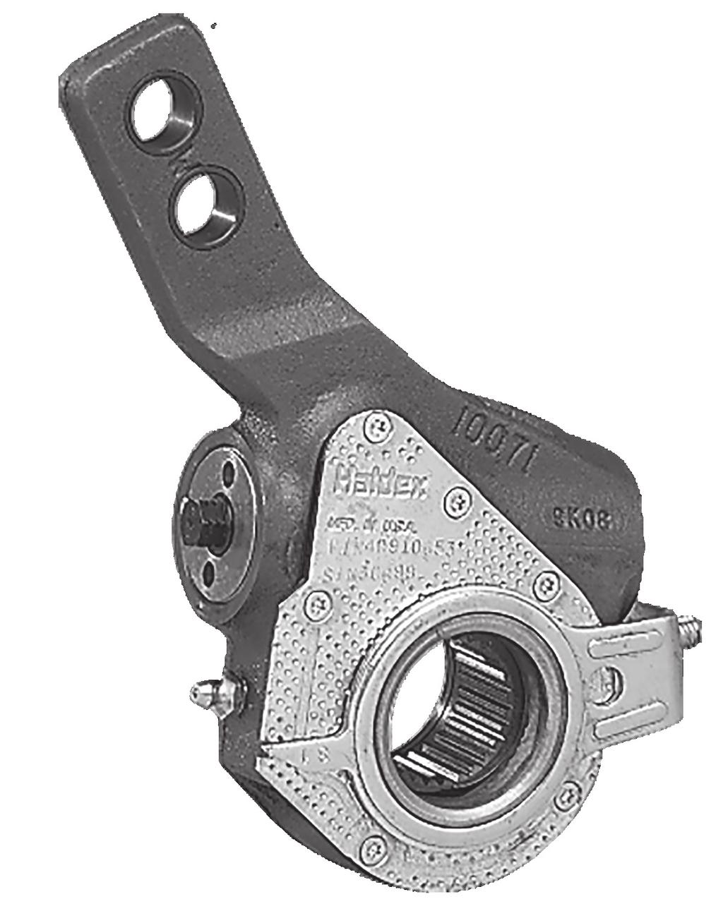
3 Operation The Haldex automatic brake adjuster is a clearance sensing brake adjuster that maintains a nominal distance or clearance between lining and drum. When the Brake Applies: Upon brake application, the brake adjuster rotates and moves the shoes into contact with the drum. The clearance notch corresponds to the normal lining-to-drum clearance. As the brake application continues, the rack moves upward and rotates the one-way clutch which slips in this direction. As the brake torque increases, the coil spring load is overcome and the wormshaft is displaced axially, releasing the cone clutch. When the Brake Releases: When the brake begins its return stroke, the coil spring load returns to normal and the cone clutch is again engaged. The rack is pulled back to its original position in the notch, and any additional travel brought about by lining wear causes the rack to turn the locked oneway clutch and rotates the wormshaft through the locked cone clutch. The wormshaft then rotates the worm wheel and camshaft, adjusting the brakes. Clutch Assembly O Ring Adjustment Hex Enclosed Rack Installation Indicator Clearance Notch Control Arm Bushing Heat Treated Housing Direction of Applied Stroke Wormshaft Coil Spring O Ring Worm Wheel Fixed Point Brake Adjuster Identification Part Number: 409 prefix = Reduced maintenance adjuster 429 prefix = No-Lube adjuster Serial Number: First 3 digits = Day of year built Last 2 digits = Year of build After Sept The Part No. P/N would be our adjuster part number Part Number P/N Serial Number S/N33489 Prior to Sept The first three numbers stamped on the cover plate is the brake adjuster part number. For example: 224 would be our adjuster part number


4 Typical Applications Steer Axle Figures 1 4 show typical brackets for automatic brake adjuster applications on steer axle brake assemblies. Refer to pages 4 and 5 for detailed installation procedures. Figure 1 Steer axle with clamp bracket and flat anchor stud Approx. 1/16 Figure 2 Steer axle with clamp bracket and round anchor stud Figure 3 Mack 16,000# or higher rated steer axles with spider mounted bracket Approx. 1/16 Figure 4 Steer axle with strap bracket Drive Axle Figures 5 8 show typical brackets for automatic brake adjuster applications on drive axle brake assemblies. Refer to pages 4 and 5 for detailed installation procedures. Figure 5 16 drive axle with strap bracket Figure 6 34 drive axle with strap bracket Figure 7 Mack drive axle with clamp bracket and flat anchor stud Figure 8 0 Kenworth drive axle with strap bracket, for 8 bag air ride 2 Note: Refer to fundamental parts identification and location on page 10.


5 Typical Applications Trailer Axle Figures 9 12 show typical brackets for automatic brake adjuster applications on trailer axle brake assemblies. Refer to pages 4 and 5 for detailed installation procedures. Figure 9 For 16-1/2 Brake Assemblies Figure 10 For 12-1/4 Brake Assemblies Figure 11 Integral cam support anchor bracket for 12-1/4 and 16-1/2 brakes Figure 12 Bolt-on cam support anchor bracket for 12-1/4 and 16-1/2 brakes Note: Refer to fundamental parts identification and location on page 10. 3


6 Installation Procedures Note: Configuration of anchor bracket and brake adjuster housing may vary, depending upon axle. Refer to typical applications on Pages 2 and 3. Step 1 Note: Block wheels to prevent vehicle from rolling. Ensure system tank pressure is above 100 PSI. Check that the push rod is fully retracted: apply air to release spring brake. If air is not available, spring brake must be manually caged back. Install anchor bracket loosely as illustrated in Figure 13. Some strap brackets have two mounting holes. Proper mounting location is determined by the length of adjuster arm. 5 and 5-1/2 adjuster arm lengths utilize the shorter hole location while 6 and 6-1/2 length adjusters utilize the longer hole locations. Do not tighten anchor bracket fasteners at this time. Apply Anti-Seize type lubricant to camshaft splines. Anchor Bracket Figure 13 Step 2 Install the brake adjuster onto the camshaft with the adjusting hex pointing away from the brake chamber as illustrated in Figure 14. Secure the brake adjuster on the camshaft. Use at least one inner washer and enough outer washers to allow no more than.060 movement of adjuster on camshaft. (Per TMC recommended practice RP609-A.) Note: Do NOT pull push rod out to meet the brake adjuster. Rotate the 7/16 adjusting hex nut CLOCKWISE until the clevis hole lines up with the brake adjuster arm hole. Apply anti-seize to clevis pin, install and secure with cotter pin. Figure 14 4
. Most adjusters will be equipped with an Installation Indicator.")
.")

. A minimum of 13 ft. lbs.")

7 Installation Procedures Step 3 Rotate the control arm away from the adjusting hex toward the air chamber, until it comes to a definite internal stop (Figure 15). Most adjusters will be equipped with an Installation Indicator. Indicator must fall within the slot for proper installation with brakes fully released (Figure 16). If the control arm position is wrong, tight brakes will occur (Figure 17). Tighten all anchor bracket fasteners (make sure the control arm does not move from its position while tightening fasteners). Figure 15 Step 4 The adjuster must be manually adjusted at this time. Rotate the adjusting hex clockwise until the lining lightly contacts the drum. Then back-off the adjuster by turning the adjusting hex counter-clockwise 1/2 of a turn (Figure 18). A minimum of 13 ft. lbs. is necessary to overcome the internal clutch. A ratcheting sound will be present. Do NOT use an impact wrench or internal damage will occur! FINAL INSPECTION. With full system air pressure, assure that spring brakes are released and check that the Installation Indicator is within the slotted area. IF NOT, REPEAT Step 3. Note: To ensure proper fit and function, always replace both adjuster and mounting bracket. Correct (Brakes released) Figure16 INCORRECT (Brakes released) Figure17 Figure 18 5
8 Routine Visual/Operational Checks Haldex strongly recommends that routine visual/operational checks, including brackets and control arms, be performed at each Preventative Maintenance Service Interval. Adjusters or anchor brackets that have visual damage, or which fail the operational checks, MUST be replaced immediately. Automatic adjusters should not be operated as manual adjusters except as may be necessary to get the vehicle off the road for service. Service and Lubrication Intervals Adjuster Type Manufacture Date Lubrication Interval Type of Lubricant Visual Check Interval Standard Adjuster Reduced Maintenance Adjuster No-Lube Adjuster Prior to 6/1/96 50,000 miles or every 3 months Standard Chassis Grease After 6/1/96 Once a year Standard Chassis Grease Each Preventative Maintenance Service Interval Each Preventative Maintenance Service Interval After 6/1/96 None Sealed Unit Each Preventative Maintenance Service Interval Notes: No-Lube automatic brake adjusters are manufactured without a grease fitting and are identified by a 429 prefix. Moly-disulfide grease should not be used because it may affect the function of the internal friction clutches and reduce the reliability of the automatic adjustment. In no case should the lubrication interval exceed the published intervals shown above. 6
9 Foundation Brake Operational Check and Troubleshooting Note: Block wheels to prevent vehicle from rolling. Ensure system tank pressure is at psi. Check that push rod is fully retracted; apply air to release spring brake. Free Stroke Measuring the Free Stroke North American Commercial Vehicle Safety Alliance (CVSA) Uniform Vehicle Inspection Criteria The applied stroke of the brake should be checked per CVSA guidelines at PSI reservoir pressure. Applied stroke should be at or less than the specified adjustment limits as follows: Standard Clamp Type Brake Chamber Type Adjustment Limit Type Adjustment Limit 9 1-3/ / / / / /4 Free stroke is the amount of movement of the adjuster arm required to move the brake shoes against the drum. With brakes released, measure from the face of the chamber to the center of the clevis pin A (Figure 19, Page 8). Use a lever to move the brake adjuster until the brake shoes contact the drum B (Figure 19, Page 8). The difference between the fully retracted and drum contact measurement B A (Figure 19, Page 8), is the free stroke. The free stroke range should fall between 3/8 3/4. Free Stroke Within Range Long Stroke Type Brake Chamber Type Adjustment Limit Type Adjustment Limit 16L 2 24LS 2-1/2 20L 2 30LS 2-1/2 24L 2 NOTE: Long stroke chambers are identified with square air ports or port bosses and special trapezoid ID tags. If the free stroke is good, but the applied stroke is too long, there is probably a problem with the foundation brake. Check the following and reference CVSA out-of-service criteria: Component Cause Action Brake drums Cracked or out of round Replace or check drum run out Brake shoes Shoe span out of spec Refer to OEM specs and replace if necessary Brake shoes Uneven lining wear Check spider concentricity Brake shoes Shoe pad missing Remove & replace shoes Brake shoes Cracked shoes Remove & replace shoes Cam bushings Excessive movement Remove & replace cam bushings per OEM specs Camshaft Flat spots on cam head Replace camshaft Camshaft Cracked/broken splines Replace camshaft Camshaft Worn bearing journals Replace camshaft Chamber bracket Broken/bent Replace bracket Clevis yoke and pin Worn Remove & replace Return springs Broken/stretched or missing Remove & replace springs Rollers Flat spots, grooved pin/worn Remove & replace roller and pin Rollers Wrong size Remove & replace with correct parts Spider anchor pins Grooved or scored/worn Replace spider or pins, as appropriate for OEM 7

10 Free Stroke Above the Range If the free stroke is above the range and the applied stroke is too long, there is a problem with the foundation brake or the adjuster. Check the following: Component Cause Action Camshaft Binding Remove, replace, lubricate camshaft Camshaft bushings Excessive movement Remove and replace cam bushings per OEM specs Camshaft bushings Binding shaft Lubricate camshaft bushings or replace Air chamber return springs Broken, weak, missing Replace chamber Air chamber push rod Binding on chamber housing Check adjuster for proper shimming and air chamber position for proper adjuster arm length Air system Not exhausting completely Check for cause of air problem and repair Shoe return springs Broken, weak, missing Replace springs Automatic brake adjuster Unknown Check automatic brake adjuster for proper installation. Refer to Installation Instructions on pages 4 & 5. Automatic brake adjuster Unknown Refer to Automatic Brake Adjuster Checking Procedures and Operational Check on pages 9 & 10. Free Stroke Below the Range If the free stroke is less than 3/8, a dragging brake can occur. Check the following: Component Cause Action Wheel bearing Out of adjustment Readjust per OEM specs Automatic brake adjuster Unknown Check automatic brake adjuster for proper control arm position. Refer to Installation Instructions on pages 4 & 5. Automatic brake adjuster Unknown Refer to Automatic Brake Adjuster Checking Procedures and Operational Check on pages 9 & 10. Free Stroke = B minus A Applied Stroke = C minus A A (Fully Retracted) B (Drum Contact Using a Lever) C (Brake Application at PSI reservoir pressure.) Figure 19 Stroke Measurements (taken from face of air chamber to center of clevis pin) 8
11 Automatic Brake Adjuster Checking Procedures If the brake adjuster is not maintaining the proper applied stroke, before removing the brake adjuster, check the condition of the foundation brake (see pages 7 & 8). If after inspecting the foundation brake no apparent problems are found, inspect the automatic brake adjuster to determine if it is operating properly. The inspection can be performed on or off the vehicle using the following procedures. On Vehicle Inspection Block wheels to prevent vehicle from rolling. Ensure system tank pressure is at PSI. Check that push rod is fully retracted; apply air to release spring brake. If air is not available, spring brake must be manually caged back. Do not use air tools on brake adjuster! Component Cause Action Tight or Control arm Realign control arm and anchor bracket. dragging brakes mispositioned Check installation procedures on pages 4 & 5. Excessive chamber push rod travel Note: Improper anchor bracket connection to control arm Low clutch torque Unknown Automatic Brake Adjuster Operational Check If anchor bracket to control arm connection is worn, loose, bent or broken, it must be re-secured or replaced. Rotate the 7/16 adjustment hex one full turn counterclockwise. Replace brake adjuster if the torque is less than 13 ft. lbs. or no racheting sound occurs. Perform automatic brake adjuster operation check (see below). Functional operation of the brake adjuster can be performed on the vehicle by using the following procedure: Note: Block wheels to prevent vehicle from rolling. Ensure system tank pressure is at PSI. Check that push rod is fully retracted; apply air to release spring brake. If air is not available, spring brake must be manually caged back. Do not use air tools on brake adjuster! Manually de-adjust brakes (turn adjustment hex counterclockwise one full turn) to create an excessive drum to lining clearance condition. (A ratcheting sound should occur.) Make a full service brake application. On release, allow sufficient time for brake to fully retract. During the brake release, observe rotation of the adjustment hex (attaching a wrench on the hex or scribing the hex will make this rotation easier to see). This rotation indicates that an excessive clearance condition has been determined by the brake adjuster, and it is making an adjustment to compensate. On each subsequent brake release, the amount of adjustment and push rod travel will be reduced until the desired clearance is achieved. If rotation of the adjustment hex is not observed, refer to Foundation Brake Operational Check and Troubleshooting Procedures on pages 7 and 8. If foundation brake assembly checks out okay and hex still does not turn, check control arm and mounting bracket for possible worn, bent or broken components. If the control arm and mounting bracket check out okay, replace the adjuster and hardware per procedures on pages 4 & 5. 9


12 Off Vehicle Inspection Component Cause Action Adjuster not functioning properly Low clutch Place adjuster arm in vise. Rotate the 7/16 torque adjustment hex counterclockwise one full turn to check de-adjustment torque. After control arm stops rotating, a minimum of 13 ft. lbs. will be required and a ratcheting sound will occur. Replace brake adjuster if the torque is less than 13 ft. lbs. or no de-adjustment ratcheting sound is present. Control Arm slippage Place adjuster arm in vise. Rotate the control arm counterclockwise until the control arm rotates to an INTERNAL STOP. If the installation indicator goes past the indicator notch or does not stop rotating (arm slips freely), replace the brake adjuster. Unknown If torque is above 13 ft. lbs., scribe a line on the adjustment hex. Manually pull the brake adjuster control arm clockwise then push back counter clockwise until the installation indicator stops in the indicator notch. The hex will move in a clockwise direction when the control arm of the brake adjuster is pushed back counterclockwise. Replace adjuster if hex does not move. Worn/missing control arm wear bushing and anchor stud pin, if applicable. Remove and replace pin and bushings. If adjuster has passed the above checks, re-install adjuster on vehicle, with new hardware. Typical Parts Identification and Location Anchor Bracket Anchor Stud Pin Adjustment Hex Nut Anchor Stud Pin Anchor Bracket Control Arm (Single Bend) Wear Bushing Wear Bushing Indicator Notch Installation Indicator Control Arm (Double Bend) 10


13 Torque Specifications Note: Tighten all fasteners to manufacturer s recommendations unless otherwise specified below. Round Anchor Stud Pin with Fabricated Ring Clamp Torque to ft. lbs. when installed Flat Anchor Stud Pin Torque to ft. lbs. when installed Round Anchor Stud Pin with Slide Nut Torque to ft. lbs. when installed 3/8-16 Nut and Bolt Torque to ft. lbs. when installed Strap Style Bracket Torque to 8-12 ft. lbs. when installed U-Bolt Style Bracket Torque to ft. lbs. when installed 11
14 Frequently Asked Questions 1. Will the side of the brake adjuster with the installation indicator always face in? No. Haldex adjusters are normally unhanded. Always install with the adjusting hex pointing away from the air chamber. 2. My adjuster doesn t have an installaton indicator; should I be concerned? No. A few applications aren t manufactured with installation indicators. However, the set-up and function are the same regardless. Refer to pages 4 & 5 for proper installation procedures. 3. Why is there resistance when backing off the adjuster? It takes approximately lb. ft. of torque to back off the adjustment hex. (A ratcheting sound should occur.) 4. How far do I back off the automatic brake adjuster at a brake reline? 1/2 turn. (NOTE: for the first 1/8 turn you may not hear the ratcheting; this is normal.) 5. How do I know if I need an offset, angled or straight-armed adjuster? Haldex manufactures the right adjuster arm for your specific application. Haldex adjusters are unhanded (no lefts or rights) in the majority of applications. Please refer to the Haldex Parts and Cross Reference Guide for your specific application (L00090). 6. Why does my replacement ABA look different from the original I took off? The Haldex ABA replacement adjuster has been designed to fit a number of applications. It is the same original equipment quality and design of the adjuster you removed; however, it may look different on the outside. If you use all the parts included in the kit, the results will be the same as the original equipment adjuster. 7. Why is the applied stroke pressure range psi at the reservoir? This is the pressure recommended by the CVSA (Commercial Vehicle Safety Alliance). Anything beyond 100 psi measures deflection within the foundation brake and not true push rod stroke. 8. Some brake chambers have round por openings and some square; what is the difference? Standard brake chambers are identified by round ports. Long stroke chambers are identified by square ports and trapezoid ID tags. 9. Can I vary the amount of lining-to-drum clearance by moving the control arm? No, that clearance is set at the factory. If long or short stroke continues, please refer to the foundation brake checking procedures on pages 7 & 8 of this manual. 10. Can I use an air ratchet on the adjuster? No. It will damage the internal mechanism of the adjuster and render it inoperative. 11. Can I access the adjuster through the rear cover? No, do not tamper with the rear cover it will release the factory set pressure on the spring and destroy the adjuster and its ability to properly function. 12. How much control arm bushing and anchor stud pin wear is acceptable before replacement is required? No more than 1/16. (continued on page 13) 12
15 Frequently Asked Questions (continued) 13. What is the acceptable amount of camshaft bushing wear? Automatic adjusters cannot compensate for worn foundation brake parts. Please refer to the foundation brake manufacturer s recommendations for maimum bushing and camshaft wear limits. 14. Can wheel bearing adjustment affect the brake adjuster? Yes. Improper wheel bearing adjustment could result in improper brake adjustment. It is necessary to refer to the axle manufacturer s wheel bearing adjustment recommendations. A loose bearing preload could cause a tight brake. 15. Are all Haldex automatic brake adjusters pre-lubed? Yes. All Haldex brake adjusters are lubricated at the factory. Please consult the Service and Lubrication Section on Page 6 for proper lubrication guidelines. 16. Can I use moly lube with the Haldex automatic brake adjuster? No. A high concentration of moly-disulfide can lower the friction capabilities in the adjusting clutch parts and decrease automatic adjustment reliability. 17. Can I purchase anchor bracket wear items separately (ie. anchor stud pins, wear bushings)? Yes. Normal wear items like anchor stud pins and wear bushings are available. Refer to the Haldex Parts and Cross Reference Guide, L Otherwise, contact Haldex Technical Assistance for the appropriate bracket kit at Does the control arm need to be properly set and secured? Yes. Without proper placement and attachment, the adjuster will not function properly. Make sure the control arm, anchor bracket and wear items are in good working order to assure the adjuster will operate as designed. 19. If automatic adjustment stops, can I operate as a manual brake adjuster? No. Completely check out foundation brake and adjuster to determine cause of problem. Repair or replace as needed to restore automatic adjustment. Additional Information Available Additional parts and service information on Haldex Automatic Brake Adjusters may be found in the following materials: Service Information Installation and Maintenance Wall Chart... L60047 Service Manual (Truck/Trailer)... L30033 Installation Tips Automatic Brake Adjuster (Pocket Size)... L20397 Parts Information Parts and Cross Reference Guide (Truck/Trailer)... L00090 Supplemental Automatic Brake Adjuster Kits... L20447 These materials are readily available on the Haldex website haldex.com, or you may order copies by contacting your Customer Service Representative at

16 Haldex develops and provides reliable and innovative solutions with focus on brake and air suspension products to the global commercial vehicle industry. Listed on the Stockholm Stock Exchange, Haldex has annual sales of approximately 3.9 billion SEK and employs about 2,200 people. To learn more, contact your Haldex sales professional. United States Canada Mexico For additional contact information or to learn more about Haldex, please visit Haldex.com L30033 US Rev. 1/18 2.5M ALP Printed In The USA
S-ABA Service Manual. Self-Setting Automatic Brake Adjusters
 S-ABA Service Manual Self-Setting Automatic Brake Adjusters Warning: Haldex strongly recommends routine visual checks be performed at EACH maintenance service interval. Foundation brake operational checks
Premium wheel-end brake products
 Premium wheel-end brake products Spicer Automatic Slack Adjuster Service Manual Self Adjusting Brake Adjuster The description and specifications contained in this service publication are current at the
L Rev. 10/04. CSI Midland/Gunite Automatic Brake Adjuster Service Manual
 L30006 Rev. 10/04 CSI Midland/Gunite Automatic Brake Adjuster Service Manual TABLE OF CONTENTS Overview...3 Installation Procedures...4 Brake Adjustment...10 Installation Procedures...11 Brake Adjustment...13
PARTS/CROSS-REFERENCE INFORMATION
 PARTS/CROSS-REFERENCE INFORMATION AA1 and S-ABA Brake Adjusters Innovative Vehicle Solutions Important Notice The products described within this literature, including without limitation, product features,
SuperTrac. Axle. Service & Maintenance. Manual
 SuperTrac Axle Service & Maintenance Manual Table of Contents Page Exploded Views Section 1: General Information General Warnings Description of Axle Models Identifications Section 2: Installation Axle
Parts and Cross Reference Guide
 Parts and Cross Reference Guide L00090 Rev. 7/07 AA1 and S-ABA Brake Adjusters www.haldex.com Table Of Contents Features Haldex ABA (AA1)............................... 1 Haldex S-ABA...................................
Module 6: Air Foundation Brakes
 Air Brakes Terms and Definitions Basic Components That Make Up Air Foundation Brakes Types of Air Foundation Brakes Parts of a Cam Foundation Brake Parts of a Wedge Foundation Brake Parts of a Disc Foundation
SERVICE BULLETIN No. 1088
 SERVICE BULLETIN No. 1088 Circulate to listed addressees COACH MODEL BULLETIN TYPE MANUAL & SECTION : T800 Series; T900 Series; T 2100 Series; C2045 : Service Information : Maintenance Manual: Chapter
SD Bendix ASA-5 Automatic Slack Adjuster DESCRIPTION OPERATION BRAKE APPLICATION GENERAL
 SD-05-1269 Bendix ASA-5 Automatic Slack Adjuster DESCRIPTION The Bendix ASA 5 automatic slack adjuster is designed for use on cam actuated drum brakes of the type in use on most highway vehicles. Like
GUNITE Service Bulletin
 Pinpointing Braking Failures Is It the Slack Adjuster? Or Is It the Foundation Brake? A slack adjuster - regardless if it s manual or automatic - is a lever used to actuate brakes. As its name implies,
Slack Adjuster. Table of Contents
 Slack Adjuster Table of Contents Sub-Headings Automatic Slack Adjuster Service 2 PayMaster Automatic Slack Adjuster 2 How the Automatic Slack Adjuster Works 2 Pressed-In, Sealed Actuator Boot 3 Handed
MGM Brakes Service Manual
 MGM Brakes Service Manual MAGNUM Performance Plus Spring Brake Actuators (MJ-Series 3.00 / 76mm Long Stroke ) For: S-Cam Tamper-Resistant MAGNUM Performance Plus Spring Brake Actuators Figure 1 A B C Your
Cam Brakes. Table of Contents
 Sub-Headings Introduction 3 Q Plus 3 Disassembly 4 Remove the Wheel Components 4 Automatic Slack Adjuster 4 Brake Shoes 5 Remove Camshaft and Auto Slack Adjuster 6 Preparing Parts for Assembly 6 Clean
Refer to separate Installation Instructions for installation details.
 OWNER S GUIDE 8A000729 DuraLift 13.5 13,500 CAPACITY Link Mfg. Ltd. 223 15th St. N.E. Sioux Center, IA USA 51250-2120 www.linkmfg.com QUESTIONS? CALL CUSTOMER SERVICE 1-800-222-6283 DEALER / INSTALLER:
SD Bendix Manual Slack Adjusters DESCRIPTION ADJUSTING MECHANISM OPERATION
 SD-05-1200 Bendix Manual Slack Adjusters WORM SHAFT (LOCK SCREW) FIGURE 1 - POSITIVE LOCK TYPE SLACK ADJUSTER DESCRIPTION In an s-cam type foundation brake, the final link between the pneumatic system
Air Brake Inspection Presented By: G.L. May
 Air Brake Inspection 2012 Presented By: G.L. May Outline of this course Objective of this course: The technician will have a better understanding of requirements for air drum brakes and air disc brakes
Webinar Series APTA Standards Quarterly Webinar Series
 1 Webinar Series APTA Standards Quarterly Webinar Series Presented by APTA Brake and Chassis Working Group Disc Brake Wheels On Inspection January 26, 2017 2 Moderator Presenter Jerry Guaracino Assistant
Air Brake Adjustment. What You ll Learn After reading this chapter you will be able to:
 8 Air Brake Adjustment Fast Fact Your company may have a maintenance crew to keep vehicles safely running. But one person alone is ultimately responsible to ensure that the brakes are operating properly
Independent Front Suspension
 Independent Front Suspension Technical Training Contents Why Independent? Tuthill Models Features and Benefits Description Special Tools Regular Maintenance Troubleshooting Available Kits Contacting Tuthill
FAST BRAKE INDEX. trouble-shooting guide
 FAST BRAKE trouble-shooting guide INDEX INTRODUCTION 3 PRECAUTIONS 3 INSPECTION 4 Q&A Why does my spring brake have square air-inlet ports? 4 Why is the yoke welded to the service push-rod? 6 What do I
Webinar Series. APTA Bus Technical Maintenance Committee Webinar Series. Disc Brake Wheels On Inspection. Presents
 1 Webinar Series APTA Bus Technical Maintenance Committee Webinar Series Presents Disc Brake Wheels On Inspection January 28, 2015 2 Introduction Welcome to today s webinar in which we will cover a wheels
OWNER S GUIDE 8A DURALIFT II 13,200 LB. CAPACITY. Link Mfg. Ltd th St. N.E. Sioux Center, IA USA
 OWNER S GUIDE 8A000715 DURALIFT II 13,200 LB. CAPACITY Link Mfg. Ltd. 223 15th St. N.E. Sioux Center, IA USA 51250-2120 www.linkmfg.com QUESTIONS? CALL CUSTOMER SERVICE 1-800-222-6283 DEALER / INSTALLER:
MGM Brakes Service Manual
 MGM Brakes Service Manual For: S-Cam Piston Type Service and Spring Brake Chambers Form No. 5009 Issued 6/91 - Revised 4/2010 MODEL MB-T SERIES MODEL MG-T SERIES Superseded by the MJS SERIES Form #5044
INSTALLATION INSTRUCTIONS 88029
 INSTALLATION INSTRUCTIONS 88029 FOR SUSPENSION SYSTEMS RS6503: JEEP WRANGLER (TJ) READ ALL INSTRUCTIONS THOROUGHLY FROM START TO FINISH BEFORE BEGINNING INSTALLATION REV F IMPORTANT NOTES! WARNING: This
NHVIM Section 2 BASIC BRAKES MAINTENANCE
 NHVIM Section 2 BASIC BRAKES MAINTENANCE Chair Lance Fisher, JLP Panel Members - Andrew Archibald, TMR Queensland - Renzo Barone, Meritor - Kevin Gibson, Knorr-Bremse Chair Lance Fisher, JLP Panel Members
MGM Brakes Service Manual
 MGM Brakes Service Manual MODEL LTR-T - 2.50 Pre 6/1/98 MODEL LTR-T - 2.50 Post 5/31/98 MODEL LTR-L3-3.00 For: Long Life Integral Release Bolt Double Diaphragm Spring Brakes Several design improvements
Troubleshooting. Pull Type Clutches - Poor Release
 Troubleshooting Pull Type Clutches - Poor Release Complaint Possible Causes Corrective Action Poor Release Intermediate plate sticking on drive lugs due to cocked drive pins (AS and EP 1402 only) (see
BRAKE SYSTEM Return To Main Table of Contents
 BRAKE SYSTEM Return To Main Table of Contents GENERAL... 2 BRAKE PEDAL... 10 MASTER CYLINDER... 13 BRAKE BOOSTER... 16 BRAKE LINE... 18 PROPORTIONING VALVE... 19 FRONT DISC BRAKE... 20 REAR DRUM BRAKE...
WD DODGE SUSPENSION LIFT KIT P/N
 4/03/03 94-01 4WD DODGE 1500 3 SUSPENSION LIFT KIT P/N 10-46094 NOTE: Each lift kit, and options to lift kits, are packaged separately. Therefore installation procedures are covered in separate instructions.
TMC Axle Installation and Service Manual
 Axle Installation TMC Axle Installation and Service Manual The Group Disclaimer Versioning The author and publisher have made their best efforts to prepare this manual, and the information contained in
Dodge 5 Lift Kit Thank you for choosing Rough Country Suspension for your Off Road needs.
 *1368BAG4* 1368BAG4 921368200 2014-16 2500 Dodge 5 Lift Kit Thank you for choosing Rough Country Suspension for your Off Road needs. Rough Country recommends a certified technician installs this system.
2013-UP 3500 Dodge 5 Lift Kit SRW
 92369200 2013-UP 3500 Dodge 5 Lift Kit SRW Thank you for choosing Rough Country Suspension for your Off Road needs. Rough Country recommends a certified technician installs this system. In addition to
Fisher 657 Diaphragm Actuator Sizes and 87
 Instruction Manual 657 Actuator (30-70 and 87) Fisher 657 Diaphragm Actuator Sizes 30 70 and 87 Contents Introduction... 1 Scope of Manual... 1 Description... 2 Specifications... 2 Installation... 3 Mounting
BRAKE SYSTEM Nissan 240SX DESCRIPTION BRAKE BLEEDING * PLEASE READ FIRST * BLEEDING PROCEDURES ADJUSTMENTS BRAKE PEDAL HEIGHT SPECS TABLE
 BRAKE SYSTEM 1990 Nissan 240SX 1990 BRAKE SYSTEMS Nissan Disc & Drum Axxess, Maxima, Pathfinder, Pickup, Pulsar NX, Sentra, Stanza, 240SX, 300ZX DESCRIPTION All brake systems are hydraulically operated
BOLT-ON AND WELD-ON FLUSH FLOOR SLIDEOUT SYSTEMS OPERATION AND SERVICE MANUAL
 BOLT-ON AND WELD-ON FLUSH FLOOR SLIDEOUT SYSTEMS OPERATION AND SERVICE MANUAL TABLE OF CONTENTS SYSTEM...... Warning........ Description...... Prior to Operation OPERATION... Main Components... Mechanical...
MERITOR ALLFIT CLEARANCE-SENSING AUTOMATIC SLACK ADJUSTERS COMPLETE PORTFOLIO TO MEET EVERY APPLICATION AND BUDGET.
 MERITOR ALLFIT CLEARANCE-SENSING AUTOMATIC SLACK ADJUSTERS COMPLETE PORTFOLIO TO MEET EVERY APPLICATION AND BUDGET. SMART ASA CHOICES FROM MERITOR. YOUR TRUSTED SOLUTIONS PROVIDER. As a leading supplier
ASSEMBLY INSTRUCTIONS FOR DYNALITE DRAG RACE FRONT HUB KIT WITH DIAMETER SOLID ROTOR PINTO / MUSTANG II
 ASSEMBLY INSTRUCTIONS FOR DYNALITE DRAG RACE FRONT HUB KIT WITH 0.75 DIAMETER SOLID ROTOR 97-978 PINTO / MUSTANG II (FIVE LUG CONFIGURATION ONLY)* PART NUMBER GROUP 0-03-B DISC BRAKES SHOULD ONLY BE INSTALLED
INSTALLATION INSTRUCTIONS
 INSTALLATION INSTRUCTIONS FRONT DISC BRAKE CONVERSION KITS: A132-1, A133, A133-1 A134, A134-1 1968-73 MUSTANG/FORD Thank you for choosing STAINLESS STEEL BRAKES CORPORATION for your braking needs. Please
INSTALLATION INSTRUCTIONS
 INSTALLATION INSTRUCTIONS REAR DISC CONVERSION KIT A136-1 1976-86 AMC 20 AXLES WITH WARN FULL FLOATING AXLE CONVERSION Thank you for choosing STAINLESS STEEL BRAKES CORPORATION for your braking needs.
1. IMPORTANT NOTICES subject to change without notice. NOTE
 1. IMPORTANT NOTICES This manual is provided to every owner of a new Deloupe trailer. The manual outlines the appropriate maintenance and operation procedure so that you as an owner/operator will get the
INSTALLATION INSTRUCTIONS
 INSTALLATION INSTRUCTIONS REAR DRUM TO DISC BRAKE CONVERSION KIT A130 JEEP CJ SERIES W/AMC-20 REAR AXLES AND 5 x 5-1/2" BOLT CIRCLE Thank you for choosing STAINLESS STEEL BRAKES CORPORATION for your braking
Product Customization Guide TSE Brakes, Inc.
 Revision Date: June 7, 2018 Revision: 4 Page: 1 of 13 CONTENTS Brake Chamber Clamp Repositioning Instructions 2-3 Mechanical Release of Spring Brakes (Caging) 4-6 Installation Instructions 7-9 Determine
HORSTMAN GREASED LIGHTNING CLUTCH
 HORSTMAN GREASED LIGHTNING CLUTCH Horstman s Greased Lightning (GL) clutch is designed for ultra high performance, and requires expert setup and a serious commitment to maintenance. Warning!!! 1. Clutch
TRAILER AXLE MAINTENANCE
 Purpose To maintain and extend the product life of the Trailer Axle product line. Safety Failure to follow the instructions provided in this manual may result in death, serious personal injury, severe
Part II NORTH AMERICAN STANDARD VEHICLE OUT-OF-SERVICE CRITERIA POLICY STATEMENT
 Part II NORTH AMERICAN STANDARD VEHICLE OUT-OF-SERVICE CRITERIA POLICY STATEMENT The purpose of this part is to identify Critical Vehicle Inspection Items and provide criteria for declaring vehicles out-of-service
Tech Note Truck 14 & 15.5 Twin Plate Cast Iron Type Installation Guidelines
 1. (14 & 15.5 ) Check condition of the flywheel. Grind to resurface or replace flywheel. Surface MUST BE machined or premature clutch failure can occur. Flywheel depth must be 2.938 (74.62mm) for 14 (350mm)
RUFNEK 80 DESIGN SERIES 001 SERVICE MANUAL INTRODUCTION AND THEORY OF OPERATION...2 ASSEMBLY NUMBER EXPLANATION...2 WINCH MODEL CODES...
 RUFNEK 80 DESIGN SERIES 001 SERVICE MANUAL INTRODUCTION AND THEORY OF OPERATION...2 ASSEMBLY NUMBER EXPLANATION...2 WINCH MODEL CODES...2!WARNING!...3 MAINTENANCE...4 GENERAL DISASSEMBLY...5 A. MOTOR DISASSEMBLY...5
12. FRONT WHEEL/FRONT BRAKE/
 12 12 12-0 SERVICE INFORMATION... 12-1 FRONT BRAKE... 12-7 TROUBLESHOOTING... 12-2 FRONT SHOCK ABSORBER... 12-18 STEERING HANDLEBAR... 12-3 FRONT FORK... 12-21 FRONT WHEEL... 12-4 SERVICE INFORMATION GENERAL
INSTALLATION INSTRUCTIONS
 INSTALLATION INSTRUCTIONS REAR DISC BRAKE CONVERSION KIT A125-3 1965-72 GM A-BODY 10 & 12 BOLT AXLES Thank you for choosing STAINLESS STEEL BRAKES CORPORATION for your braking needs. Pleases take the time
Sisu S-Cam Drum Brakes
 Sisu S-Cam Drum Brakes (For hub reduction rear axles since 1992) Maintenance Manual Sisu Axles, Inc. Autotehtaantie 1 P.O. Box 189 FIN-13101 Hämeenlinna Finland Phone int + 358 204 55 2999 Fax int + 358
Product Catalogue. Version 8.0. Section. FUWA Axle Components
 Product Catalogue Section E Version 8.0 FUWA Section E Fuwa - Cam and Brake Assembly E:48 PRODUCT CATALOGUE 8.0 Fuwa - Cam and Brake Assembly Part List - 6 axle tube (square) - 5 axle tube (round) TL-11-427-800045
TROUBLESHOOTING SPECIAL TOOL ASSEMBLY AND ADJUSTMENT
 1 INDEX Models FD, FE, FF and SG REAR AXLE 10-1 10-108E-07 CHAPTER 10 REAR AXLE Models FD, FE, FF and SG TROUBLESHOOTING...10-2 10 SPECIAL TOOL...10-3 WHEEL HUB AND RELATED PARTS DISASSEMBLY...10-7 INSPECTION...10-9
TMC TRAILER AXLE SERVICE MANUAL DRUM BRAKE AXLES
 8 8 TMC Australia a Pty Ltd TMC TRAILER AXLE SERVICE MANUAL DRUM BRAKE AXLES TMC 0 59 TMC TRAILER AXLE TMC TRAILER AXLE TMC TRAILER AXLE TM 0 5 9 TMC Australia Pty Ltd Telephone: + 6 3 8786 3688 78 Star
INSTALLATION INSTRUCTIONS
 INSTALLATION INSTRUCTIONS INSTALLATION INSTRUCTIONS FOR A136 REAR DRUM TO DISC BRAKE CONVERSION KIT for 1970-75 Jeep, CJ SERIES with Dana 44 flanged axle Thank you for choosing STAINLESS STEEL BRAKES CORPORATION
12. FRONT WHEEL/FRONT BRAKE/
 12 4.5kgm 0.9kg-m 4.5kg-m 12-0 SERVICE INFORMATION... 12-1 HYDRAULIC BRAKE... 12-10 TROUBLESHOOTING... 12-2 FRONT SHOCK ABSORBER... 12-16 FRONT WHEEL... 12-3 STEERING HANDLEBAR... 12-19 FRONT BRAKE...
INSTALLATION INSTRUCTIONS
 INSTALLATION INSTRUCTIONS FX4 ELITE REAR DISC CONVERSION KITS WITH INTERNAL PARKING BRAKE A110-14, A111-25, A111-29 for FORD 8" & 9" REAR ENDS Thank you for choosing STAINLESS STEEL BRAKES CORPORATION
INSTALLATION INSTRUCTIONS
 INSTALLATION INSTRUCTIONS R1 REAR DRUM TO DISC BRAKE CONVERSION KIT A130-3 JEEP CJ SERIES W/AMC-20 REAR AXLES AND 5 x 5-1/2" BOLT CIRCLE Thank you for choosing STAINLESS STEEL BRAKES CORPORATION for your
SECTION steering mechanism
 07-302.01/ 1 2011MR17 SECTION 07-302.01 GENERAL Description See Figure 1. The includes the steering wheel (1), the steering column, the miter box (3), the steering shafts (2 and 4), and the drag link (7).
INSTALLATION INSTRUCTIONS
 INSTALLATION INSTRUCTIONS FRONT DISC BRAKE CONVERSION KITS A148-9 & A148-15 1949-54 Chevy Trucks Thank you for choosing STAINLESS STEEL BRAKES CORPORATION for your braking needs. Please take the time to
INSTALLATION/SERVICE MANUAL
 INSTALLATION/SERVICE MANUAL External Pressure Sensor Transducer Intelligent Trailer (L31295W) haldex.com Important Notice The products described within this literature, including without limitation, product
INSTALLATION INSTRUCTIONS
 INSTALLATION INSTRUCTIONS REAR DISC BRAKE CONVERSION KIT A125-2 1955-70 FULL SIZE CHEVROLET Thank you for choosing STAINLESS STEEL BRAKES CORPORATION for your braking needs. Pleases take the time to read
I-BEAM & TUBULAR STEERABLE AXLES FRONT AXLE PUSHER & TAG SERVICE MANUAL ISO 9001
 I-BEAM & TUBULAR STEERABLE AXLES FRONT AXLE PUSHER & TAG SERVICE MANUAL ISO 9001 INDEX THIS MANUAL COVERS THE FULL LINE OF WESTPORT AXLES. Section Description Page No. Section I General Information...
Heavy Duty Miniature Quick-Change Applicator (End-Feed Type) with Mechanical or Air-Feed Systems
 with Mechanical or Air-Feed Systems") Heavy Duty Miniature Quick-Change Applicator (End-Feed Type) with Mechanical or Air-Feed Systems Instruction Sheet 408-8039 02 JUN 16 Rev G Ram Post Wire Disc Insulation Disc Insulation Crimper Stripper
Heavy Duty Miniature Quick-Change Applicator (End-Feed Type) with Mechanical or Air-Feed Systems Instruction Sheet 408-8039 02 JUN 16 Rev G Ram Post Wire Disc Insulation Disc Insulation Crimper Stripper
Heavy Duty Miniature Quick-Change Applicator (Side-Feed Type) with Mechanical or Air Feed Systems
 with Mechanical or Air Feed Systems") Heavy Duty Miniature Quick-Change Applicator (Side-Feed Type) with Mechanical or Air Feed Systems Instruction Sheet 408-8040 30 NOV 17 Rev H Ram Assembly Ram Post Locking Screw Stock Drag Drag Release
Heavy Duty Miniature Quick-Change Applicator (Side-Feed Type) with Mechanical or Air Feed Systems Instruction Sheet 408-8040 30 NOV 17 Rev H Ram Assembly Ram Post Locking Screw Stock Drag Drag Release
INSTALLATION INSTRUCTIONS
 INSTALLATION INSTRUCTIONS REAR DISC BRAKE CONVERSION KIT A126-1 1973-87 CHEVROLET 1/2 TON 2WD Thank you for choosing STAINLESS STEEL BRAKES CORPORATION for your braking needs. Pleases take the time to
PARTS LIST INTRAAX AAT 23K, 25K, 30K, AAEDT 30K AND AANT 23K
 PARTS LIST INTRAAX AAT 23K, 25K, 30K, AAEDT 30K AND AANT 23K LIT NO: L405 DATE: January 2002 REVISION: E TABLE OF CONTENTS SUSPENSION AND AXLE COMPONENTS...........................................2, 4,
ASSEMBLY. Transmission Automatic Transmission 5R44E and 5R55E. Special Tool(s)
") 307-01-1 Automatic Transmission 5R44E and 5R55E 307-01-1 ASSEMBLY Transmission Special Tool(s) Holding Fixture, Transmission 307-262 (T93T-77002-AH) Special Tool(s) Installer, Transmission Extension Housing
307-01-1 Automatic Transmission 5R44E and 5R55E 307-01-1 ASSEMBLY Transmission Special Tool(s) Holding Fixture, Transmission 307-262 (T93T-77002-AH) Special Tool(s) Installer, Transmission Extension Housing
REAR SUSPENSION GROUP CONTENTS GENERAL DESCRIPTION REAR SUSPENSION DIAGNOSIS LOWER ARM AND TOE CONTROL ARM ASSEMBLY...
 34-1 GROUP 34 CONTENTS GENERAL DESCRIPTION........... 34-2 DIAGNOSIS.... 34-2 INTRODUCTION....................... 34-2 TROUBLESHOOTING STRATEGY........ 34-2 SYMPTOM CHART..................... 34-3 SYMPTOM
TECHNICAL BULLETIN. TP Issued Servicing Rockwell s TB Series Trailer Axles with Unitized Hub Assemblies
 TECHNICAL BULLETIN TP-96175 Issued 12-96 Servicing Rockwell s TB Series Trailer Axles with Unitized Hub Assemblies TB Series Trailer Axles Introduction Rockwell s TB series trailer axle features a permanently
Sofa Slideout Assembly OWNER'S MANUAL. Rev: Page 1 Sofa Slideout Owners Manual
 Sofa Slideout Assembly OWNER'S MANUAL Rev: 06.14.2016 Page 1 Sofa Slideout Owners Manual TABLE OF CONTENTS Warning, Safety, and System Requirement Information 3 Product Information 3 Prior to Operation
Group 4 CONTENTS DATA AND SPECIFICATIONS
 PARKING BRAKE 1 Group 4 PARKING BRAKE CONTENTS Paragraph Page Parking Brake 5 4 Disassembly Assembly Adjustment Parking Brake Cable 6 5 Removal Installation Service Diagnosis 1 2 DATA AND SPECIFICATIONS
PARTS LIST TRAILER BRAKE SYSTEMS. LIT NO: DATE: October 2017 REVISION: H
 PARTS LIST TRAILER BRAKE SYSTEMS LIT NO: 97-097 DATE: October 07 REVISION: H TABLE OF CONTENTS INTRODUCTION ABBREVIATIONS DRUM BRAKES & 6. DRUM FOUNDATION BRAKE HXS Brakes P-TYPE DRUM FOUNDATION BRAKE
97-06 JEEP TJ/LJ LONG ARM UPGRADE KIT
 921663U00 97-06 JEEP TJ/LJ LONG ARM UPGRADE KIT Thank you for choosing Rough Country for your suspension needs. This kit is an upgrade kit only. This kit includes frame mounting points and adjustable long
RideStar RHP Series Sliding Tandem Trailer Air Suspension System
 Maintenance Manual 14S RideStar RHP Series Sliding Tandem Trailer Air Suspension System Revised 05-14 Service Notes About This Manual This manual provides the correct lubrication, service and installation
3/16 BC20001, Rev 6. Brakes. free-backing ASSEMBLY CALIBRATION OPERATION REPLACEMENT PARTS. Page 1
 3/16 BC20001, Rev 6 Brakes free-backing UNI-servo ASSEMBLY CALIBRATION OPERATION REPLACEMENT PARTS Page 1 WARRANTY POLICY, OPERATOR MANUALS & REGISTRATION Go online to www.demco-products.com to review
TOYOTA 4-RUNNER KIT 5 KIT
 92173600 1990-1995 TOYOTA 4-RUNNER KIT 5 KIT Thank you for choosing Rough Country for all your suspension needs. Rough Country recommends a certified technician install this system. In addition to these
1984 Dodge W250 PICKUP
 1984 Dodge W250 PICKUP Submodel: Engine Type: V8 Liters: 5.2 Fuel Delivery: CARB Fuel: GAS Dana 44 MODELS THROUGH 1984 2. Raise and safely support the vehicle, then remove the wheel hub and bearings as
Brakes. FREE BACKING # Right # Left. UNI-SERVO # Right # Left. Page 1. 1/15 BC20011, Rev 6
 1/15 BC20011, Rev 6 Brakes FREE BACKING #01971 - Right #01970 - Left UNI-SERVO #07911 - Right #07910 - Left ASSEMBLY CALIBRATION OPERATION REPLACEMENT PARTS Page 1 WARNING: To Prevent Serious Injury or
CHAPTER 14 PARKING BRAKE
 1 page INDEX1 PARKING BRAKE 14-1 14-143E-05 CHAPTER 14 PARKING BRAKE 1Models FA and FB with LF05S TROUBLESHOOTING...14-2 SPECIAL TOOLS...14-3 INSPECTION AND ADJUSTMENT...14-4 PARKING BRAKE...14-7 14 PARKING
FRONT SUSPENSION GROUP 2 FRONT SUSPENSION 2-1 CONTENTS SPECIFICATIONS VC-1, VC-2, VC-3 VY-1 TOOL LIST. Page
 GROUP 2 FRONT SUSPENSION CONTENTS Page Specifications 1 Tool List.... 1 Torque Reference 2 Preparation for Measuring Front End Alignment... 2 Front Suspension Height Adjustment 3 Front Suspension Alignment
Before equipment use, please read this operation manual carefully. Serial Number: Date Purchased:
 Pushed & Geared Trolleys OPERATION MANUAL This operation manual is intended as an instruction manual for trained personnel who are in charge of installation, maintenance, repair etc. Before equipment use,
Maintenance and Parts Manual ADZ Series Suspension
 Maintenance and Parts Manual ADZ Series Suspension XL-PS10452MM-en-US Rev C Contents Contents Page Introduction... 3 Warranty... 3 Notes, Cautions, and Warnings... 3 Section 1 General Safety Instructions...
DODGE 3 SUSPENSION LIFT KIT
 921351200 Kit Contents: 9280:Front Coil Springs 1351BOX1: Upper Control Arms Lower Control Arms Sway bar Brackets Brake Proportioning Valve Bracket Track Bar Relocation Bracket 1351BOX2: 5.75 Blocks U-bolt
ASSEMBLY INSTRUCTIONS
 ASSEMBLY INSTRUCTIONS FOR DYNALITE PRO SERIES REAR PARKING BRAKE KIT WITH.9 DIAMETER VENTED ROTOR (. OFFSET) 005 - PRESENT MUSTANG 8.8 (5 LUG) PART NUMBER GROUP 0-98 INSTALLATION OF THIS KIT SHOULD ONLY
SD Bendix DD-3 & SD-3 Safety Actuators PUSH PLATE & SHAFT ASSY. LOCKPORT SERVICE DIAPHRAGM SEPARATOR LOCKING PISTON O-RING LOCKING PISTON
 SD-02-4600 Bendix DD-3 & SD-3 Safety Actuators AUXILIARY DIAPHRAGM SERVICE DIAPHRAGM SEPARATOR PUSH PLATE & SHAFT ASSY. LOCKING PISTON O-RING LOCKING PISTON LOCKPORT DRAIN SLOT RETURN SPRING CAP O-RING
Kits (with shocks), (no shocks) Audi B9
, (no shocks) Audi B9") Kits 78670 (with shocks), 78671 (no shocks) Audi B9 Rear Application MN-1074 (011808) ERN 8788 INSTALLATION GUIDE For maximum effectiveness and safety, please read these instructions completely before
Kits 78670 (with shocks), 78671 (no shocks) Audi B9 Rear Application MN-1074 (011808) ERN 8788 INSTALLATION GUIDE For maximum effectiveness and safety, please read these instructions completely before
GftOUP 4 PARKING BHAKE
 PARKING BRAKE 4-1 GftOUP 4 PARKING BHAKE CONTENTS Page Data and Specifications... 1 External Contracting Type Parking Brake...... 2 Parking Brake Band Lining 3 Parking Brake Internal Expanding Type 5 Parking
COMPETITION ENGINEERING. 80 Carter Drive P.O. Box 1470 Guilford, CT Phone: (203) Fax: (203)
 Fax: (203)") INSTALLATION INSTRUCTIONS P/N S: C2090 & C2092 SLIDE-A-LINK The Slide-A-Link by Competition Engineering is designed for use in Stock Eliminator and Bracket Racing vehicles. The rigid front mount assembly
INSTALLATION INSTRUCTIONS P/N S: C2090 & C2092 SLIDE-A-LINK The Slide-A-Link by Competition Engineering is designed for use in Stock Eliminator and Bracket Racing vehicles. The rigid front mount assembly
Maintenance Information
 16573347 Edition 2 February 2014 Air Grinder Series 88H Maintenance Information Save These Instructions Product Safety Information WARNING Failure to observe the following warnings, and to avoid these
***Be sure that the loaded trailer weight does not exceed 24,000 lbs. or the vertical load rating does not exceed 6000 lbs.
 April 2006 INSTALLATION INSTRUCTIONS MODEL NO. 70680 07068 24K 5th Wheel with Heavy Duty EZ-ROLLER For use on shortbed P/U applications US Pat. No. 6247720 PARTS INCLUDE: 1. 1675-07 Head Assembly (1) 15.
IBT Series Square Drive Torque Wrenches
 IBT Series Square Drive Torque Wrenches Operation and Maintenance Manual Model.75, 1, 3, 5, 8, 10, 20, 25, 35, 50 http://www.torsionx.com Use the IBT Series Square Drive Torque Wrenches Model.75, 1, 3,
Levelling valve
 Levelling valve 464 006 Application Purpose Maintenance Vehicles with conventionally controlled air-suspension. Control of a constant ride height of the chassis by charging the air-suspension while compressing
INSTALLATION INSTRUCTIONS P/N S: C2091 & C2093 SLIDE-A-LINK
 INSTALLATION INSTRUCTIONS P/N S: C2091 & C2093 SLIDE-A-LINK The Slide-A-Link by Competition Engineering is designed for use in Stock Eliminator and Bracket Racing vehicles. The rigid front mount assembly
/3500 Dodge 5 Lift Kit Drop Brackets
 923913000A 2003-07 2500/3500 Dodge 5 Lift Kit Drop Brackets Thank you for choosing Rough Country Suspension for your Off Road needs. Rough Country recommends a certified technician installs this system.
 Page 1 of 22 SECTION 307-01: Automatic Transaxle/Transmission 4R70E/4R75E ASSEMBLY Procedure revision date: 05/29/2009 Transmission Printable View (1554 KB) Special Tool(s) Air Test Plate, Transmission
INSTALLATION INSTRUCTIONS
 INSTALLATION INSTRUCTIONS REAR DISC BRAKE CONVERSION KIT A158 1994-97 Dodge Ram 1500 (2WD & 4WD) and REAR DISC BRAKE CONVERSION KIT A158-1 1998-01 Dodge Ram 1500 (2WD & 4WD) Thank you for choosing STAINLESS
HUB & WHEEL INSTALLATION
 HUB & WHEEL INSTALLATION 1.0 SCOPE This specification covers the torque requirements for the attachment of all component parts of Spoke Wheels, Rims, Tyres and Hub assemblies. 1.1 Spoke Wheels CAUTION:
4WD RANGER/BRONCO II WD EXPLORER CLASS II INSTALLATION INSTRUCTIONS
 4WD RANGER/BRONCO II 8-97 4WD EXPLORER 90-94 CLASS II INSTALLATION INSTRUCTIONS Before beginning the installation, read these instructions and the enclosed driver s WARNING NOTICE thoroughly and completely.
INSTALLATION INSTRUCTIONS
 INSTALLATION INSTRUCTIONS REAR DISC CONVERSION KIT A126-2 1988-98 C1500 2WD 10" REAR DRUM Thank you for choosing STAINLESS STEEL BRAKES CORPORATION for your braking needs. Pleases take the time to read
Parking brake Mechanical brake acting on rear wheels
 11 Brake System 11.1 General SPECIFICATIONS EJTC0010 Master cylinder Type Tandem type I.D. mm(in.) 20.64 mm (0.813 in.) Fluid level warning sensor Provided Brake booster Type Vacuum Boosting ratio 4.0