|
|
|
- Mervyn Fowler
- 6 years ago
- Views:
Transcription
1
2
3
4
5
6
7
8
9


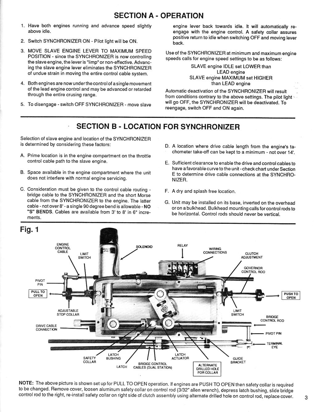
10 YNCHRONIZER AUTOMATIC SYNCHRONIZE TROUBLESHOOTING GUIDE SOLENOID (MODEL 1750) RELAY ASSEMBLY LIMIT SWITCH ENGINE CABLE CABLE TO ENGINE THROTTLE RED COLLAR ADJUST LIMIT SWITCH OPERATION BRIDGE CABLE CONTROL CABLE TO HELM STATION GUIDE BRACKET BRIDGE CABLE TERMINAL ADJUST HERE FOR BRIDGE CABLE OVERTRAVEL LIMIT SWITCH BRIDGE CABLE TERMINAL ADJUST HERE FOR BRIDGE CABLE OVERTRAVEL LIMIT SWITCH CLUTCH ADJUSTMENT SCREW ENGINE CABLE TERMI- NAL ADJUST HERE FOR THROTTLE CABLE OVER- TRAVEL TACH SENDER EXTENSIONS SCREW IN HERE RED COLLAR ADJUST LIMIT SWITCH OPERATION
11 GENERAL GUIDELINES FOR TROUBLESHOOTING 1) As a first step, verify that synchronizer is working electrically. If necessary apply voltage directly to solenoid. 2) When testing Synchronizer operation, move control handles to mid-travel position before turning Synchronizer ON. Some problems, such as idle speed limit switch or lead engine drive cable failure can be hidden if Synchronizer is turned ON at idle engine speed. 3) If Synchronizer does not appear to be matching engine speeds exactly, manually synchronize engines (by ear). Observe tachometer readings. Turn ON Synchronizer and observe changes in slave engine speed. 4) If mechanical drive adapter fails very radpidly (less than 4-6 months), mechanical drive adapter is misaligned. 5) If Synchronizer has suddenly stopped operating, determine if other work was performed on boat recently. Sometimes other work such as engine governor repairs or control cable replacements, can change Synchronizer cable adjustments causing problems with Synchronizer operation. 6) If slave engine speed varies, determine if lead engine speed is also varying. When Synchronizer is operating, it will attempt to continuously match slave engine to lead engine speed. If lead engine RPM varies or fluctuates, Synchronizer will strive to repeat variation / fluctuation in speed of slave engine. Of course, Synchronizer has no control of lead engine RPM; the Synchronizer only controls slave engine speed. 7) IF Synchronizer has been electrically activated, and IF Synchronizer is receiving RPM signal from both engines with correct input rotation, and IF Synchronizer clutch is not slipping->synchronizer must operate; unit will attempt to exactly match slave engine speed with lead engine. PROBLEM / SYMPTOM: SYNCHRONIZER DOES NOT ACTIVATE WHEN CONTROL SWITCH IS TURNED ON. 1) Pilot light may not illuminate 2) Synchronizer solenoid doesn t make any noise 3) When moving slave engine handle after turning on switch, engine accelerates. Slave engine is not disengaged from slave engine control. When Synchronizer control switch is turned on, power should be applied to synchronizer solenoid input terminals. When power is applied to solenoid input terminals, it will make a sharp, metallic, sound and slave engine handle will be disconnected from slave engine control. Fuse is blown Broken power supply or ground connection wire Relay assembly / limit switch failure A fuse is typically installed at the control switch. Check and / or replace fuse. (10 amps at 12 VDC; 5 amps at 24 or 32 VDC) Power supply to synchronizer (relay box terminal #1) or ground wire (relay box terminal #2) connections may have broken or become disconnected. Check for voltage across relay box terminals #1 and #2 when switch is turned on; if none; verify wiring connections. Change ground wire connection at relay box from terminal #2 to terminal #3. If unit becomes operational, replace relay box assembly 12 VDC relay PN or 32 VDC relay PN NOTE: Synchronizer may be used temporarily with ground wire connected to terminal #3. Limit switches will be disabled; avoid using synchronizer at idle or full throttle speed when limit switches are disabled.
12 Limit switch collars ( red collars ) are not set correctly Solenoid failure Move slave engine control handle away from idle speed position. Turn switch off and on. If synchronizer now activates, idle speed limit switch is incorrectly set. Disconnect wires from solenoid and apply correct voltage directly to solenoid terminals. If solenoid does not make any noise, solenoid has failed. PROBLEM / SYMPTOM: SYNCHRONIZER SOLENOID CHATTERS OR REPEATEDLY CLICKS WHEN CONTROL SWITCH IS TURNED ON. 1) Pilot light is dim 2) Solenoid may hum instead of clicking or chattering 3) Fuse may blow after short time When Synchronizer control switch is turned on, the solenoid requires a large amount of power (approximately 20 amps) to pull in its internal plunger. Low voltage Check voltage applied to solenoid terminals when synchronizer is turned on. At least 90% of full rated voltage must be applied to solenoid terminals during startup. Voltage may be reduced due to corroded or too small power supply or ground wire connections, low battery, etc. To test solenoid, use wire jumpers to apply battery voltage directly to solenoid terminals. Hold-in coil of solenoid defective. Replace solenoid Synchronizer clutch is over-tightened If the synchronizer clutch is overtightened, the solenoid will not be able to completely pull in the internal plunger. Readjust clutch (see manual Section K). PROBLEM / SYMPTOM: AFTER TURNING ON SYNCHRONIZER, PILOT LIGHT GOES OUT AFTER SEVERAL SECONDS. None When Synchronizer control switch is turned on, the pilot light should remain on. Synchronizer should be able to operate at any speed between idle and full throttle. If slave engine idle is set at a speed higher than lead engine idle, synchronization will not be possible at idle speed. Synchronizer turning off automatically on idle speed limit switch. Idle speed limit switch is improperly set Slave engine tach input to synchronizer has failed Advance lead engine to RPM above idle before turning on Synchronizer. If desired to operate Synchronizer with lead engine at idle speed, have engine technician reset lead engine idle speed to 25 RPM above slave engine idle speed. Readjust idle speed limit switch, obtaining 1/16 to 1/8 gap between limit switch button and red collar when engine governor / throttle is at full throttle mechanical stop. Check for failure in tachometer drive input from slave engine to Synchronizer. Problem can occur in drive cable, engine outlet drive joint, or in mechanical drive adapter.
13 PROBLEM / SYMPTOM: WHILE OPERATING WITH SYNCHRONIZER ON, OR IMMEDIATELY AFTER TURNING ON SYNCHRONIZER, SLAVE ENGINE RPM MOVES QUICKLY TO IDLE. 1) Pilot light may go out when slave engine speed reaches idle. 2) If lead engine tach input to Synchronizer has failed, helm station tachometer for lead engine may indicate 0 RPM. When Synchronizer is operating, speed of slave engine will be matched with speed of lead engine. If tachometer information from lead engine to Synchronizer indicates that lead engine has slowed or stopped, Synchronizer will try to match slave engine RPM, reducing slave engine speed to minimum (idle) speed. Lead engine tach input to Synchronizer has failed Improper tachometer cable rotation PROBLEM / SYMPTOM: Check for failure in tachometer drive input from lead engine to Synchronizer. Problem can occur in drive cable, engine outlet drive joint, or in mechanical drive adapter. Be sure to check the following: DRIVE CABLE cable core failure, cable end tip failure DRIVE JOINT on many engines, a drive joint provides tachometer information to the Synchronizer. Disconnect the tachometer cable from the drive joint, start the engine, and verify that the outlet of the drive joint is rotating. MECHANICAL DRIVE ADAPTER if a mechanical drive adapter has been installed on the engine, check the flex shaft for failure (broken cable, missing tip tang). Flex shafts will fail due to misalignment or lack of lubrication. Reinstall the flex shaft following the instructions contained in the technical manual. The Synchronizer is sensitive to the direction of the input tach cable rotation. For new system installations, or after work is done to the engine, it is possible that the tachometer cable rotation input is incorrect. Verify that the cable input rotation is installed per the matrix chart in the Technical Manual (Section E). WHILE OPERATING WITH SYNCHRONIZER ON, OR IMMEDIATELY AFTER TURNING ON SYNCHRONIZER, SLAVE ENGINE RPM MOVES QUICKLY TO FULL THROTTLE. 1) Pilot light may go out when slave engine speed reaches full throttle. 2) If slave engine tach input to synchronizer has failed, helm station tachometer for slave engine may indicate 0 RPM. When Synchronizer is operating, speed of slave engine will be matched with speed of lead engine. If tachometer information from slave engine to Synchronizer indicates that slave engine has slowed or stopped, Synchronizer will try to match slave engine RPM, increasing slave engine speed to full throttle speed. Lead engine tach input to Synchronizer has failed Improper tachometer cable rotation Check for failure in tachometer drive input from lead engine to Synchronizer. Problem can occur in drive cable, engine outlet drive joint, or in mechanical drive adapter. Be sure to check the following: DRIVE CABLE cable core failure, cable end tip failure DRIVE JOINT on many engines, a drive joint provides tachometer information to the Synchronizer. Disconnect the tachometer cable from the drive joint, start the engine, and verify that the outlet of the drive joint is rotating. MECHANICAL DRIVE ADAPTER if a mechanical drive adapter has been installed on the engine, check the flex shaft for failure (broken cable, missing tip tang). Flex shafts will fail due to misalignment or lack of lubrication. Reinstall the flex shaft following the instructions contained in the technical manual. The Synchronizer is sensitive to the direction of the input tach cable rotation. For new system installations, or after work is done to the engine, it is possible that the tachometer cable rotation input is incorrect. Verify that the cable input rotation is installed per the matrix chart in the Technical Manual (Section E).
14 PROBLEM / SYMPTOM: Synchronizer turning OFF automatically on full speed limit switch. (This is a normal function of the Synchronizer). Full speed limit switch is improperly set Slave engine tach input to Synchronizer has failed PROBLEM / SYMPTOM: WHILE OPERATING WITH SYNCHRONIZER ON AT OR NEAR WIDE OPEN THROTTLE (WOT), SYNCHRONIZER TURNS OFF BY ITSELF / PILOT LIGHT GOES OUT. None The Synchronizer should be able to operate at any speed between idle and full throttle. If the lead engine is able to operate at a higher top end speed than the slave engine can run at, the Synchronizer may turn itself off since it will not be possible to synchronize at this speed. None Turn Synchronizer control switch OFF and ON to reset Synchronizer. If pilot light turns OFF again, it is likely that the full speed limit switch is being activated it is not possible for the Synchronizer to operate at this RPM. If it is necessary to run at wide open throttle, operate engines manually (Synchronizer OFF). If it is desireable to operate the boat with the Synchronizer ON, reduce the speed of the lead engine by RPM and turn Synchronizer back ON. Readjust full speed limit switch, obtaining 1/16 to 1/8 gap between limit switch button and red collar when engine governor / throttle is at full throttle mechanical stop. Check for failure in tachometer drive input from slave engine to Synchronizer. Problem can occur in drive cable, engine outlet drive joint, or in mechanical drive adapter. SYNCHRONIZER OPERATION IS SLUGGISH; SLAVE ENGINE SPEED DOES NOT ALWAYS MATCH LEAD ENGINE SPEED. If the Synchronizer is turned ON with a 100 RPM differential between the two engine speeds, approximately 5-6 seconds will be required to synchronize the engine speeds. If there is a larger speed difference when the Synchronizer is turned ON, a longer time will be required to match engine speeds. For a RPM speed differential between engines, perhaps seen when making large changes in the lead engine RPM, approximately seconds will be required to adjust and match engine speeds. Synchronizer clutch is slipping. Adjust Synchronizer clutch as described in the manual Section K. PROBLEM / SYMPTOM: AFTER TURNING SYNCHRONIZER OFF, SLAVE ENGINE CONTROL HANDLE IS NOT ABLE TO CONTROL SLAVE ENGINE SPEED. None When Synchronizer control switch is turned OFF, manual control of the slave engine must be reestablished. This is normally accomplished by moving the slave engine control handle back to the idle speed position, allowing the bridge control cable to be reconnected mechanically to the engine control cable. Lack of bridge cable overtravel terminal eye on the control cable from helm station control is incorrectly adjusted. Readjust the terminal eye on the bridge control cable at the Synchronizer to achieve proper overtravel see Section J of the manual. NOTE: 1) If the overtravel adjustment is slightly OFF, slave engine control may be regained by very rapidly pulling the slave engine handle back to the idle position. On a 2-station boat, try regaining manual control at the other helm station. 2) The overtravel adjustment can be thrown off by improper adjustment of the stop screws at the control head.
15 SYNCHRONIZER PARTS LIST Part Number Item Description Part Number Item Description Solenoid 12 volt (new style) C Cable clamp Solenoid 24 volt (new style) Cable shim Solenoid 32 volt (new style) Term eye (33C - 43C) Solenoid 12 volt - SL (old style) Red - Stop collar Solenoid 24 volt - SL (old style) Bearing retainer (1-2-3) Solenoid 32 volt - SL (old style) Long control rod Relay assembly - Sync 12 volt Short control rod Relay assembly - Sync 24 volt Sync worm shaft Relay assembly - Sync 32 volt Guide bracket Clutch cable assembly Switch bracket C Cable clamp Tach sender extension Solenoid 12v-1750(new style) Solenoid 24v-1750(new style) Solenoid 32v-1750(new style) Solenoid 12v-SL(old style) Solenoid 24v-SL(old style) Solenoid 32v-SL(old style) C cable clamp C cable clamp Cable shim Relay Assy. 12v Relay Assy. 24v Relay Assy. 32v Term Eye (33/43C) Clutch Cable Assy Red Collar Long Control Rod Short Control Rod Clutch Assy Worm Shaft Bearings Bearing Retainer Guide Bracket Worm Shaft WP001 - Camplate Assy.
SYNCHRONIZE YNCHRONIZER AUTOMATIC TIC TROUBLESHOOTING GUIDE RELAY ASSEMBLY SOLENOID (MODEL 1750) LIMIT SWITCH ENGINE CABLE CABLE TO
 LIMIT SWITCH ENGINE CABLE CABLE TO") YNCHRONIZER SYNCHRONIZE AUTOMATIC TIC TROUBLESHOOTING GUIDE SOLENOID (MODEL 1750) RELAY ASSEMBLY LIMIT SWITCH ENGINE CABLE CABLE TO ENGINE THROTTLE RED COLLAR ADJUST LIMIT SWITCH OPERATION BRIDGE CABLE
YNCHRONIZER SYNCHRONIZE AUTOMATIC TIC TROUBLESHOOTING GUIDE SOLENOID (MODEL 1750) RELAY ASSEMBLY LIMIT SWITCH ENGINE CABLE CABLE TO ENGINE THROTTLE RED COLLAR ADJUST LIMIT SWITCH OPERATION BRIDGE CABLE
ELECTRICAL. Contents - Wiring Diagrams
 Contents - Wiring Diagrams T-Bar (Floating Deck - Hydro)............................................ 8-16 T-Bar (Fixed Deck - Gear)............................................... 8-17 T-Bar (Fixed Deck
Subject Underhood G System Error Codes and Symptoms System or Parts affected
 System or Parts affected Index Underhood70G (V90Gxxx) System or Parts affected... 1 Overview... 1 Identifying your System... 1 Retrieving Logged Error Messages... 1 Error Messages... 3 Error Message Table...
Troubleshooting Guide
 Troubleshooting Guide P/N 0153180 July 1999 P.O. Box 1160 St. Joseph, MO 64502-1160 1-800-255-0317 Fax: 816-360-9379 www.snorkelusa.com GENERAL INFORMATION This manual contains procedures for locating
Service Manual for Battery Control Center
 Service Manual for Battery Control Center P/N 82 E0071 00 (Ref. 81 1317) June, 1999 Battery Control Box Operation Charging Circuit This function charges the coach battery from the engine alternator while
A. Welding Control Module. 2. Control Models WC.12RO & WC.24RO -- Location of Internal Indicators and Fuses
 IX. Trouble/Fault Diagnosis (after successful installation) The ZENA mobile welding system has been designed to be very simple to use. In addition, no expense has been spared to insure that it is also
Self-Adjust Clutch Installation Guide
 Self-Adjust Clutch Installation Guide 0 STOP! READ CAREFULLY BEFORE INSTALLING CLUTCH This clutch must be installed by a qualified installer. Improper installation or failure to replace or resurface the
CI 3000 Coil Inserter
 CI 3000 Coil Inserter Setup & Operator Manual Issue 1 April 02 Performance Design Inc. The CI 3000 plastic spiral inserter will bind books up to 1-1/8 (28.6mm) thick using coil diameters from 3/16 (5mm)
SALDET SALES & SERVICE, INC. CLINTON TOWNSHIP, MICHIGAN
 Form 1254 BRAKETRON Electronic Motor Brake Instructions SALDET SALES & SERVICE, INC. CLINTON TOWNSHIP, MICHIGAN TABLE OF CONTENTS SECTION TITLE PAGE I. Introduction 1 II. Specifications 1 III. Principles
Table of Contents Operations Overview CONTROL HEAD OPERATIONS AND KEYPAD OPERATIONS AT-A-GLANCE...pg 1 System Startup EXPLAINS THE PROCESS OF
 Complete Controls Operators Guide v0. Table of Contents Operations Overview CONTROL HEAD OPERATIONS AND KEYPAD OPERATIONS AT-A-GLANCE........................................pg System Startup EXPLAINS THE
GENERAL <ELECTRICAL>
 00E-1 GROUP 00E GENERAL CONTENTS HARNESS CONNECTOR INSPECTION................... 00E-2............. 00E-6................. 00E-6 TROUBLESHOOTING STEPS.......... 00E-6 INFORMATION FOR DIAGNOSIS.......
User Manual. T6 Tachometer. Online: Telephone: P.O. Box St. Petersburg, Florida 33736
 User Manual T6 Tachometer Online: www.phareselectronics.com Telephone: 727-623-0894 P.O. Box 67251 St. Petersburg, Florida 33736 Table of Contents Overview... 1 Description... 1 Wiring... 1 T6 Tachometer
STANDARD AND GROUND SWITCHED APPLICATIONS
 SNOWDOGG LIGHT REFERENCE STANDARD AND GROUND SWITCHED APPLICATIONS GENERAL REFERENCE SNOWDOGG LIGHT REFERENCE GENERAL REFERENCE 3 TROUBLESHOOTING GUIDES/PROCEDURES 6 CONNECTOR REFERENCE 12 ADAPTER HARNESS
Troubleshooting Guide
 Troubleshooting Guide diesel - gasoline - LPG P/N 0172021 June 1999 P.O. Box 1160 St. Joseph, MO 64502-1160 1-800-255-0317 Fax: 816-360-9379 www.snorkelusa.com GENERAL INFORMATION This manual contains
BASIC TROUBLE SHOOTING (PERFECTPASS FOR MECHANICAL ENGINES) How PerfectPass Works
 How PerfectPass Works") BASIC TROUBLE SHOOTING (PERFECTPASS FOR MECHANICAL ENGINES) How PerfectPass Works Through the in-dash display the driver sets the desired boat speed or engine RPM depending upon which mode of operation
BASIC TROUBLE SHOOTING (PERFECTPASS FOR MECHANICAL ENGINES) How PerfectPass Works Through the in-dash display the driver sets the desired boat speed or engine RPM depending upon which mode of operation
VAGABOND S HANDBOOK TRANSMISSION
 03/24/07 TRANSMISSION Transmission won t engage into Gear This is caused usually by too low a Voltage to get into the ECM. This unit requires a minimum of 9VDC in order to operate at all. Almost all erratic
CPi. CoiL PACK IGNiTioN FOR AViATiON. For 4,6 and 8 cylinder 4 stroke applications. Please read the entire manual before beginning installation.
 1 CPi CoiL PACK IGNiTioN FOR AViATiON Coil pack (4 cylinder) Coil pack (6 cylinder) For 4,6 and 8 cylinder 4 stroke applications. Please read the entire manual before beginning installation. Software version
Electronic Products ELECTRONIC MAINTENANCE
 SubDrive2W, 75, 100, 150, 300, MonoDrive, and MonoDrive XT Should an application or system problem occur, built-in diagnostics will protect the system. The FAULT light or digital display on the front of
GENERAL <ELECTRICAL>
 00E-1 GROUP 00E GENERAL CONTENTS HARNESS CONNECTOR INSPECTION................................. 00E-2............. 00E-6................. 00E-6 TROUBLESHOOTING STEPS.......... 00E-6 INFORMATION
SHORT-STOP. Electronic Motor Brake Type G. Instructions and Setup Manual
 Electronic Motor Brake Type G Instructions and Setup Manual Table of Contents Table of Contents Electronic Motor Brake Type G... 1 1. INTRODUCTION... 2 2. DESCRIPTION AND APPLICATIONS... 2 3. SAFETY NOTES...
GLENDINNING ONTROL QUICK REFERENCE GUIDE. (see Operations Manual for more detailed information)
") GLENDINNING EL E C T NGINE C R O N I C ONTROL QUICK REFERENCE GUIDE (see Operations Manual for more detailed information) EEC QUICK REFERENCE GUIDE - TABLE OF CONTENTS SYSTEM STARTUP CRUISE MODE WARM UP
GLENDINNING EL E C T NGINE C R O N I C ONTROL QUICK REFERENCE GUIDE (see Operations Manual for more detailed information) EEC QUICK REFERENCE GUIDE - TABLE OF CONTENTS SYSTEM STARTUP CRUISE MODE WARM UP
2015 EDITION SUBMERSIBLE MOTORS AIM MANUAL. APPLICATION INSTALLATION MAINTENANCE 60 Hz, Single-Phase and Three-Phase Motors. franklinwater.
 0 EDITION AIM MANUAL SUBMERSIBLE MORS APPLICATION INSTALLATION 60 Hz, Single-Phase and Three-Phase Motors franklinwater.com All Motors System Troubleshooting Motor Does Not Start A. No power or incorrect
oubleshooting Guide diesel - gasoline - LPG electric P.O. Box 1160 St. Joseph, MO Fax:
 Troub oubleshooting Guide diesel - gasoline - LPG electric P/N 0162737 October 2005 P.O. Box 1160 St. Joseph, MO 64502-1160 1-800-255-0317 Fax: 785-989-3075 www.snorkelusa.com GENERAL INFORMATION This
Troubleshooting Manual
 Troubleshooting Manual NOTICE: DO NOT DISCARD THIS MANUAL Models: LEGACY42-IFT PHOENIX42-IFT 1 TABLE OF CONTENTS A. Normal Operation...3 B. Wiring Diagram...4 C. Troubleshooting IntelliFire Touch...5 D.
2000 F-150 Workshop Manual
 Page 1 of 14 SECTION 303-06: Starting System 2000 F-150 Workshop Manual DIAGNOSIS AND TESTING Procedure revision date: 06/17/1999 Starting System Refer to Wiring Diagrams Cell 20, Starting System for schematic
ESD5500E Series Speed Control Unit
 ESD5500E Series Speed Control Unit 1 SPECIFICATIONS INTRODUCTION PERFORMANCE Isochronous Operation ± 0.25% or better Speed Range / Governor 1-7.5 KHz Continuous Speed Drift with Temperature ±1% Maximum
BOLT-ON AND WELD-ON FLUSH FLOOR SLIDEOUT SYSTEMS OPERATION AND SERVICE MANUAL
 BOLT-ON AND WELD-ON FLUSH FLOOR SLIDEOUT SYSTEMS OPERATION AND SERVICE MANUAL TABLE OF CONTENTS SYSTEM...... Warning........ Description...... Prior to Operation OPERATION... Main Components... Mechanical...
Detroit Speed, Inc. RS Electric Headlight Door Kit 1969 Camaro P/N: (3)
") Detroit Speed, Inc. RS Electric Headlight Door Kit 1969 Camaro P/N: 122001 (3) (1) (2) (5) (4) Figure 1 Item QTY Description 1 1 LH actuator w/bracket and linkage 2 1 RH actuator w/bracket and linkage
Detroit Speed, Inc. RS Electric Headlight Door Kit 1969 Camaro P/N: 122001 (3) (1) (2) (5) (4) Figure 1 Item QTY Description 1 1 LH actuator w/bracket and linkage 2 1 RH actuator w/bracket and linkage
Table No. 1 provides a means of identifying the various alternator systems. Note: All output figures are rated at 3600 RPM. TABLE NO.
 The alternator systems installed on Briggs & Stratton Intek OHV-Twin Cylinder Engines can easily be identified by the color of the stator output wires and the connector. Table No. 1 provides a means of
Page 1 of 1 ALTERNATORS. Overview. Intek TM V-Twin Cylinder OHV Engine Service Manual Version 1.0. Copyright 1999 by Briggs and Stratton Corporation
 Overview Alternator Identification Page 1 of 3 The alternator systems installed on Briggs & Stratton Intek V-Twin Cylinder OHV Engines can easily be identified by the color of the stator output wires and
CRUISE CONTROL SYSTEM
 CRUISE CONTROL SYSTEM 1988 Jeep Cherokee 1988 Cruise Control Systems JEEP CRUISE COMMAND All Models DESCRIPTION & OPERATION Jeep vehicles use an electro-mechanical servo system. The system consists of
Main 20 A fuse has blown (2) Connector has come off PCB
 Connector has come off PCB") ELECTRICAL FAULT FINDING OMS TRACTORS C & A from September 00 D&K series from April 00 JCB from Jan 00 Note: This Bulletin must be used in conjunction with the correct wiring diagram for the Tractor being
ELECTRICAL FAULT FINDING OMS TRACTORS C & A from September 00 D&K series from April 00 JCB from Jan 00 Note: This Bulletin must be used in conjunction with the correct wiring diagram for the Tractor being
WEBER CARBURETOR TROUBLESHOOTING GUIDE
 This guide is to help pinpoint problems by diagnosing engine symptoms associated with specific vehicle operating conditions. The chart will guide you step by step to help correct these problems. For successful
SERVICE SHOP NOTES. Use ohmmeter to check the resistance between the leads.
 SERVICE SHOP NOTES LIMA MAC SELF VOLTAGE REGULATED GENERATORS Troubleshooting Tips Symptom: Engine bogs down or stalls even at no load. Problem: Main stator has one or more taps wound or connected incorrectly.
Troubleshooting. Pull Type Clutches - Poor Release
 Troubleshooting Pull Type Clutches - Poor Release Complaint Possible Causes Corrective Action Poor Release Intermediate plate sticking on drive lugs due to cocked drive pins (AS and EP 1402 only) (see
2002 F-150 Workshop Manual
 Page 1 of 23 SECTION 310-03: Speed Control 2002 F-150 Workshop Manual DIAGNOSIS AND TESTING Procedure revision date: 08/07/2006 Speed Control Refer to Wiring Diagrams Cell 31, Speed Control for schematic
DIAGNOSTIC TROUBLESHOOTING INDEX
 DIAGNOSTIC TROUBLESHOOTING INDEX Curtis Industries, LLC. 111 Higgins Street Worcester, MA 01606 Telephone: (508) 853-2200 Fax: (800) 876-9104 www.snoproplows.com TROUBLESHOOTING INDEX - BY PROBLEM Section
RE Generation II Troubleshooting Guide Section I Preliminary Information and Evaluation
 DODGE ENGINEERING & CONTROLS, INC. 196 Riverneck Road Chelmsford, MA 01824 PHONE (978) 244-1200 FAX (978) 244-1422 TOLL FREE (877) 334-2875 RE Generation II Troubleshooting Guide Section I Preliminary
MAGNAMAX DVR DIGITAL VOLTAGE REGULATOR
 MAGNAMAX DVR DIGITAL VOLTAGE REGULATOR TECHNICAL MANUAL MODEL DVR 2000 AND DVR 2000C FIGURE 1 - FRONT AND REAR VIEW OF VOLTAGE REGULATOR...4 SECTION 1- INTRODUCTION...5 GENERAL DESCRIPTION...5 SPECIFICATIONS...5
ICM325HN. Head Pressure Control with Optional Heat Pump Override. Installation, Operation & Application Guide
 ICM325HN Head Pressure Control with Optional Heat Pump Override Temperature sensitive control regulates head pressure Installation, Operation & Application Guide For more information on our complete range
th Street, Surrey, B.C. Canada V3W 0A6 Telephone Fax July 2012
 8238-129 th Street, Surrey, B.C. Canada V3W 0A6 Telephone 604-572-3935 Fax 604-590-8313 http://www.kobelt.com 7173-KAS MANUAL July 2012 Leaders in Quality Marine Controls, Steering Gear, and Disc Brakes.
CHAPTER 10 ELECTRIC SYSTEM
 CHAPTER 10 ELECTRIC SYSTEM 1. ELECTRIC SYSTEM ELECTRIC SYSTEM 1.1 WIRING DIAGRAM CK20-USA 196WA00A S196-WOO Jul. 2003 10-3 CK20(M) CHAPTER 10 CK20-EU 196WA51A 10-4 S196-WOO Jul. 2003 ELECTRIC SYSTEM 1.2
CUMMINS FAULT CODE: 1239 PID: SPN: 2623 FMI: 3/3 LAMP: AMBER
 CUMMINS ACCELERATOR PEDAL OR LEVER POSITION SENSOR 2 CIRCUIT - VOLTAGE ABOVE NORMAL OR HORTED TO HIGH SOURCE FAULT CODE: 1239 PID: SPN: 2623 FMI: 3/3 LAMP: AMBER DESCRIPTION ISX and ISM Accelerator Pedal
Controller Ground (dual black 12awg) should be connected to chassis ground as close as possible to the battery.
 should be connected to chassis ground as close as possible to the battery.") 1. Overview The Maximizer 4 progressive nitrous controller operates one or two separate stages of nitrous based on either time, RPM, MPH, throttle percentage or boost pressure. Whether your engine is naturally
1. Overview The Maximizer 4 progressive nitrous controller operates one or two separate stages of nitrous based on either time, RPM, MPH, throttle percentage or boost pressure. Whether your engine is naturally
Identify and understand the key components to the starting and charging system. Rotating Electrical Troubleshooting Guide. Battery.
 Rotating Electrical Troubleshooting Guide Battery Alternator Identify and understand the key components to the starting and charging system. Starter Motor TRUE SPECIALISTS CHOOSE EFEL 1 Efel_Trouble_Shooting_Guide_ENG_2016.indd
HD 7700 Setup & Operator Manual
 HD 7700 Setup & Operator Manual Issue 1 December, 01 Performance Design Inc. The Heavy Duty Ultima (HD 7700) electric punch has been designed to punch most any job that may pass through your bindery or
TD80 LEVEL GAUGING & OVERFILL PREVENTION SYSTEM PRODUCT MANUAL. TPM 001 Revision 0.1
 TD80 LEVEL GAUGING & OVERFILL PREVENTION SYSTEM PRODUCT MANUAL Revision 0.1 3 TD80 and Overfill Prevention System Troubleshooting Equipment Required: 1. Automotive Test light, 6VDC to 24VDC 2. Short length
Service Bulletin. (This bulletin and all other active bulletins are downloadable from our website at
 Bulletin 00--ABDE Service Bulletin (This bulletin and all other active bulletins are downloadable from our website at www.frymaster.com/parts_service.) Bulletin 00--ABDE Page of + Worksheets Date: 0//00
RODIX, INC. FC-40-PLC Plus Series Control Troubleshooting Guide for Circuit Board P/Ns and
 RODIX, INC. FC-40-PLC Plus Series Control Troubleshooting Guide for Circuit Board P/Ns 24-488 and 24-489 Control must be connected to a known GOOD LOAD prior to testing Problem: No output from the control
GRD502-B Flow Chart 02/05/09
 PINPOINT TEST A: NO PROVE OUT OF ANY LEDs prove out (all LED's light up) of the LED's when module power is applied or module "wakes up", indicates that: - the Guardian module does not have power. - the
Detroit Speed, Inc. Electric Headlight Door Kit Corvette P/N: &
 Detroit Speed, Inc. Electric Headlight Door Kit 1968-82 Corvette P/N: 122006 & 122007 The Detroit Speed Inc. Electric Headlight Door Kit replaces the stock vacuum actuated system on all 1968-82 Corvettes.
HORN OPERATION DIAGNOSIS MOST GM VEHICLES 1967 AND UP
 Revised: 27OC2010 HORN OPERATION DIAGNOSIS MOST GM VEHICLES 1967 AND UP All General Motors vehicles (from the 60s through the 80s) have a horn or horns that operate on the same basic principle. When you
Sofa Slideout Assembly OWNER'S MANUAL. Rev: Page 1 Sofa Slideout Owners Manual
 Sofa Slideout Assembly OWNER'S MANUAL Rev: 06.14.2016 Page 1 Sofa Slideout Owners Manual TABLE OF CONTENTS Warning, Safety, and System Requirement Information 3 Product Information 3 Prior to Operation
Body Electrical System
 Body Electrical System GENERAL....BE -2 MULTI FUNCTION SWITCH...BE -8 HORN...BE -11 FUSES AND RELAYS...BE -12 INDICATORS AND GAUGES...BE -19 LIGHTING SYSTEM...BE -24 DAYTIME RUNNING LIGHTS...BE -30 BE-2
A/C SYSTEM GENERAL DIAGNOSTIC PROCEDURES
 Article Text ARTICLE BEGINNING 1993 AIR CONDITIONING & HEAT A/C General Diagnostic Procedures Diagnosis is an important first step in A/C system servicing. To save time and effort, systems should be carefully
Throttle-by-wire. MasterCraft Technical Training Vonore, Tennessee USA. A MasterCraft Technical Services Publication
 Throttle-by-wire MasterCraft Technical Training Vonore, Tennessee USA A MasterCraft Technical Services Publication MasterCraft University 2008-2009 Throttle-by-wire Page 1 Electronic Throttle Control Description
1998 E-Series Workshop Manual
 SECTION 206-09A: Anti-Lock Control Rear DIAGNOSIS AND TESTING Procedure revision date: 02/08/2000 Anti-Lock Control Refer to Wiring Diagrams Cell 42, Speed Control for schematic and connector information.
Wiring diagrams on page 29 are for reference only. For detailed vehicle wiring refer to Navistar documents.
 1 10/2014 REV 7 !!Attention!! Before performing diagnostics: Wiring diagrams on page 29 are for reference only. For detailed vehicle wiring refer to Navistar documents. Check for Fault Codes using the
ACSI MODEL 1406BB-04-AO POWER SUPPLY INSTALLATION INSTRUCTIONS
 II 1400-10 ACSI MODEL 1406BB-04-AO POWER SUPPLY INSTALLATION INSTRUCTIONS Features: Up to 1.95 Amps Load Capacity Class 2 Rated Outputs Overload, Over Voltage, and Short Circuit Protection Standby Battery
Detroit Speed, Inc. RS Electric Headlight Door Kit 1968 Camaro P/N: (3)
") Detroit Speed, Inc. RS Electric Headlight Door Kit 1968 Camaro P/N: 122002 (3) (1) (2) (5) (4) Figure 1 Item QTY Description 1 1 LH Actuator w/bracket and Linkage 2 1 RH Actuator w/bracket and Linkage
Detroit Speed, Inc. RS Electric Headlight Door Kit 1968 Camaro P/N: 122002 (3) (1) (2) (5) (4) Figure 1 Item QTY Description 1 1 LH Actuator w/bracket and Linkage 2 1 RH Actuator w/bracket and Linkage
Important Information
 Table of Contents Important Information Section 1C - Troubleshooting Troubleshooting 1 C Jetdrive Troubleshooting...1C-2 Jetdrive Unit Troubleshooting...1C-2 Performance Troubleshooting...1C-4 Hard Steering...1C-5
ICM 326HN/327HN Line Voltage Head Pressure Control Installation, Operation & Application Guide
 ICM 326HN/327HN Line Voltage Head Pressure Control With built-in transformer Optional heat pump override ICM326HN ICM327HN Installation, Operation & Application Guide For more information on our complete
MODEL JH JACKSHAFT INDUSTRIAL DOOR OPERATOR INSTALLATION MANUAL. OPERATOR SPECIALTY COMPANY, INC. P.O. Box 128 Casnovia, MI 49318
 MODEL JH JACKSHAFT INDUSTRIAL DOOR OPERATOR INSTALLATION MANUAL OPERATOR SPECIALTY COMPANY, INC. P.O. Box 128 Casnovia, MI 49318 OSCO requires the use of a reversing edge or photoelectric control for pedestrian
# Traction Control Window Switch
 1 INSTRUCTIONS # 82085 Traction Control Window Switch Thank you for choosing products; we are proud to be your manufacturer of choice. Please read this instruction sheet carefully before beginning installation,
Troubleshooting Bosch Proportional Valves
 Troubleshooting Bosch Proportional Valves An Informative Webinar Developed by GPM Hydraulic Consulting, Inc. Instructed By Copyright, 2009 GPM Hydraulic Consulting, Inc. TABLE OF CONTENTS Bosch Valves
ESCONDIDO FIRE DEPT TRAINING MANUAL Section DRIVER OPERATOR Page 1 of 13 Pumps and Accessory Equipment Revised
 DRIVER OPERATOR Page 1 of 13 PUMPS AND ACCESSORY EQUIPMENT Pumps are designed for many different purposes. In order to understand the proper application and operation of a pump in a given situation, firefighters
ARCHITECTURAL CONTROL SYSTEMS, INCORPORATED ST. LOUIS, MISSOURI
 II 1400-6 ARCHITECTURAL CONTROL SYSTEMS, INCORPORATED ST. LOUIS, MISSOURI ACSI 1426-04-AO ELECTRIC LATCH RETRACTION CONTROLLER INSTALLATION INSTRUCTIONS I.D. 1092, REV. C INSTALLATION For C-UL Listed applications,
For the most current information, visit the Roadranger web site at
 Eaton Fuller Automated Transmissions AutoShift Gen II Models Quick Reference Guide TRMT-0062 March 2000 For the most current information, visit the Roadranger web site at www.roadranger.com General Warnings:
INSTALLATION AND OWNER S MANUAL MODEL T Trolley Operator
 INSTALLATION AND OWNER S MANUAL MODEL T Trolley Operator Serial #: Date Installed: Your Dealer: READ THIS MANUAL CAREFULLY BEFORE INSTALLATION OR USE. SAVE THESE INSTRUCTIONS. As of date of manufacture,
EEC4 Electronic Engine Controls by Glendinning. Installation Manual
 EEC4 Electronic Engine Controls by Glendinning Installation Manual Glendinning Marine Products, Inc. 740 Century Circle Conway, SC 29526 www.glendinningprods.com REVISED: 03/05 Table of Contents i Chapters
2003 F-Super Duty /Excursion Workshop Manual
 3//2011 SECTION 310-03: Speed Control 2003 F-Super Duty 250-550/Excursion Workshop Manual DIAGNOSIS AND TESTING Procedure revision date: 08/01/2006 Speed Control Printable View (331 KB) Refer to Wiring
Service and Parts Manual. NO LONGER IN PRODUCTION Some service parts may not be available for this product. Otolaryngology Chair.
 thru 391-001 -002 Otolaryngology Chair Serial Number Prefixes: EN, PD & V Service and Parts Manual NO LONGER IN PRODUCTION Some service parts may not be available for this product. 391-001 thru -002 NOTE:
Modulating Furnace Information. Warning on Meter Setting - Read First!
 Modulating Furnace Information Pressure Transducer Pressure DC Volts 0.00" 0.25 0.20" 0.63 0.25" 0.72 0.30" 0.82 0.35" 0.91 0.40" 1.00 0.45" 1.09 0.50" 1.19 0.55" 1.28 0.60" 1.38 0.65" 1.47 0.70" 1.56
APOLLO Gate Operators, Inc.
 APOLLO Gate Operators, Inc. Model 3500ETL/3600ETL Commercial Swing Gate Operator INSTALLATION MANUAL 01/08 CONTENTS IMPORTANT SAFETY INSTRUCTIONS. 3 Applications... 4 Pre-Installation Checklist... 5 Parts
ELECTRICAL / GENERAL INFORMATION
 ELECTRICAL / GENERAL INFORMATION General Information Reading Electrical Schematics The schematic is made up of individual circuits laid out in a sequence of related functions. It is formatted with all
Troubleshooting the Transmission Hydraulic System
 Testing and Adjusting IT28F INTEGRATED TOOLCARRIER POWER TRAIN Testing And Adjusting Introduction Reference: For Specifications with illustrations, refer to SENR5974, IT28F Integrated Toolcarrier Power
TrimSync Race Edition Installation & Operating Instructions
 TrimSync Race Edition Installation & Operating Instructions Mounting the Device The unit should be mounted in a dry area away from sources of heat. Mounting the unit near the trim pumps will reduce wiring
Troubleshooting Guide
 Troubleshooting Guide diesel - gasoline - LPG diesel - gasoline - LPG diesel - gasoline - LPG P/N 0191681 May, 1999 An ISO 9001 Registered Company P.O. Box 1160 St. Joseph, MO 64502-1160 1-800-255-0317
ENGINE GOVERNING SYSTEMS
 ENGINE GOVERNING SYSTEMS ESD5400 Series Speed Control Unit INSTALLATION The speed control unit is rugged enough to be placed in a control cabinet or engine mounted enclosure with other dedicated control
SLIDEOUT SYSTEM SERVICE MANUAL
 e SYNC SLIDEOUT SYSTEM SERVICE MANUAL 82 S0347 09 02 TABLE OF CONTENTS PAGE # SERVICE MANUAL 1 1. SERVICE PARTS 2 4 2. REPLACEMENT PARTS & KITS 4 2.1 MECHANICAL COMPONENTS 4 2.2 ELECTRICAL COMPONENTS 4
ELECTRICAL TABLE OF CONTENTS
 ELECTRICAL TABLE OF CONTENTS Electrical Table of Contents General Information...205 Reading Electrical Schematics...205 Theory Of Operation Information...206 Diagnostic Information...206 Wire Color Abbreviation
FOR New Electric Kit and Remote Control Installation
 Installation Manual COMMAND-10 REMOTE AND COMMAND STATION FOR New Electric Kit and Remote Control Installation Use these in place of the rocker switch and solenoid section of instructions in your roll
THROTTLE & RPM-ACTIVATED NITROUS CONTROL SYSTEM P/N 15970NOS
 THROTTLE & RPM-ACTIVATED NITROUS CONTROL SYSTEM P/N 15970NOS Installation Instructions 199R10300 INTRODUCTION: Congratulations on the purchase of your NOS throttle and RPM-activated nitrous control system!
INSTALLATION AND OWNER S MANUAL MODEL T Trolley Door Operator
 INSTALLATION AND OWNER S MANUAL MODEL T Trolley Door Operator UL 325 and UL 991 Listed Serial #: Date Installed: Your Dealer: READ THIS MANUAL CAREFULLY BEFORE INSTALLATION OR USE. SAVE THESE INSTRUCTIONS.
Garden Tractor Clutch
 P-1097-6 819-0458 Garden Tractor Clutch Troubleshooting and Installation Guide Contents Terminology........................... 2 Troubleshooting Checklist................ 3 Electrical Evaluation.....................
LIPPERTCOMPONENTS, INC.
 LIPPERTCOMPONENTS, INC. SCHWINTEK INWALL SLIDEOUT SYSTEM OPERATION AND SERVICE MANUAL Contents I. Controls 1-1 System components 1 1-1A versions C1 & C2 2 1-2 Motor wiring harness connections 3 1-3 Extend
11712 Jefferson Ave, Suite C-#446 Newport News, VA Website: Office (757)
") 11712 Jefferson Ave, Suite C-#446 Newport News, VA 23606 E-mail: mpusupport@allteksystems.com Website: www.allteksystems.com Office (757) 546-0742 Manual and Users Guide Version B.4 2 Thank you for purchasing
11712 Jefferson Ave, Suite C-#446 Newport News, VA 23606 E-mail: mpusupport@allteksystems.com Website: www.allteksystems.com Office (757) 546-0742 Manual and Users Guide Version B.4 2 Thank you for purchasing
Reproduction or other use of this Manual, without the express written consent of Vulcan, is prohibited.
 SERVICE MANUAL ELECTRIC BRAISING PANS (30 & 40 GALLON) VE30 VE40 ML-126849 ML-126850 VE40 SHOWN - NOTICE - This Manual is prepared for the use of trained Vulcan Service Technicians and should not be used
OnCommand Troubleshooting Guide Hayward Industries
 OnCommand Troubleshooting Guide 2010 Hayward Industries Table of Contents Safety Precautions Page 1 Overview Pages 2-5 Software Troubleshooting Page 6 Local Display Pages 7-8 Relays Pages 9-10 Heaters
Gas Spreader PLUS Remote Kit With Built in Clutch Relay and On/Off Switch
 Gas Spreader PLUS Remote Kit With Built in Clutch Relay and On/Off Switch NOTE: Read all directions first before continuing. This wireless controller kit has been programmed and tested before shipping.
TRACTION CONTROL SYSTEM (TCL)
") 35C-1 GROUP 35C TRACTION CONTROL SYSTEM (TCL) CONTENTS GENERAL DESCRIPTION 35C-2 DIAGNOSIS 35C-4 INTRODUCTION TO TRACTION CONTROL SYSTEM DIAGNOSIS 35C-4 TCL DIAGNOSTIC TROUBLESHOOTING STRATEGY 35C-4 DIAGNOSTIC
35C-1 GROUP 35C TRACTION CONTROL SYSTEM (TCL) CONTENTS GENERAL DESCRIPTION 35C-2 DIAGNOSIS 35C-4 INTRODUCTION TO TRACTION CONTROL SYSTEM DIAGNOSIS 35C-4 TCL DIAGNOSTIC TROUBLESHOOTING STRATEGY 35C-4 DIAGNOSTIC
CRUISE CONTROL SYSTEM
 CRUISE CONTROL SYSTEM 1994 Toyota Celica 1994 ACCESSORIES & EQUIPMENT Toyota Motor Sales, U.S.A., Inc. - Cruise Control Systems Celica DESCRIPTION Cruise control system consists of Cruise Control Electronic
Trouble Shooting. Symptom Possible Cause Solution Power switch ON but switch Light is Off. Main power to unit Off. Switch light defective.
 Trouble Shooting TE: Should the OAM Purger shut down on a FAULT condition, DO T POWER OFF THE PURGER until you have first removed the electrical panel cover and recorded the status of the indicator LED
Detroit Speed, Inc. Electric Headlight Door Kit Corvette P/N: &
 Detroit Speed, Inc. Electric Headlight Door Kit 1968-82 Corvette P/N: 122006 & 122007 The Detroit Speed Inc. Electric Headlight Door Kit replaces the stock vacuum actuated system on all 1968-82 Corvettes.
File: 12-fc131 Page 1 of 11. Fault Code 131 CODES REASON EFFECT
 File: 12-fc131 Page 1 of 11 Fault Code 131 Accelerator Pedal or Lever Position Sensor Circuit - Voltage Above Normal, or Shorted to High Source CODES REASON EFFECT Fault Code: 131 PID(P), SID(S): P091
COLDWATER LAKE FACILITIES DUPLEX PUMP STATION
 COLDWATER LAKE FACILITIES DUPLEX PUMP STATION TROUBLESHOOTING GUIDE REFERENCE: Operation Instructions Ladder Schematic Diagrams SCOPE The following troubleshooting guide has been specifically prepared
Hydraulic Maintenance & Troubleshooting. Content - Norman Kronowitz Presenter Jim Trinkle
 Hydraulic Maintenance & Troubleshooting Content - Norman Kronowitz Presenter Jim Trinkle Introduction Welcome to the CMA/Flodyne/Hydradyne s Hydraulic Troubleshooting presentation. We will introduce many
4-1. Engine Starting Procedure
 CSP-CI-ll Section IV Normal Procedures 4-1. Engine Starting Procedure CAUTION Do not abuse the overspeed limiter by starting the engine with the throttle open excessively, or by suddenly advancing throttle
KE-4 Installation/Operation Instruction Manual FT033
 KE-4 Installation/Operation Instruction Manual FT033 Electronic Control System Electronic Control System Thumb Tab Guide Trolling Module Handheld Control Engine Synchronization Trolling Module Handheld
SUREPOWR TM SERIES -SURE 49 FIELD INSTALLATION INSTRUCTIONS
 SUREPOWR TM SERIES -SURE 49 FIELD INSTALLATION INSTRUCTIONS Safety First In the maintenance and operation of mechanical equipment, SAFETY is the basic factor which must be considered at all times. Through