Cylinder Installation Compression/Stripper, for Models, 22HF, 16HF, 1600 machines
|
|
|
- Allen Baker
- 6 years ago
- Views:
Transcription


1 Knowledge Base Article Type: Instructions Cylinder Installation Compression/Stripper, for Models, 22HF, 16HF, 1600 machines Description: Instructions on How to properly install stripper beam and compression head cylinders. Included is information on the Safety Beam Stops kit. WARNING Never work on, clean or service this unit, control panel or any machine or open or remove any protective cover, guard, grate, door, or maintenance panel until the power or energy sources has been turned off, locked out / tagged out, and all moving parts have come to a complete stop and or blocked to prevent movement. Machinery is dangerous avoid personal injury and or death by following manufacture, Local, and OHSA safety procedures. Contact Columbia Machine for safety decals, guards, horns and beacons.

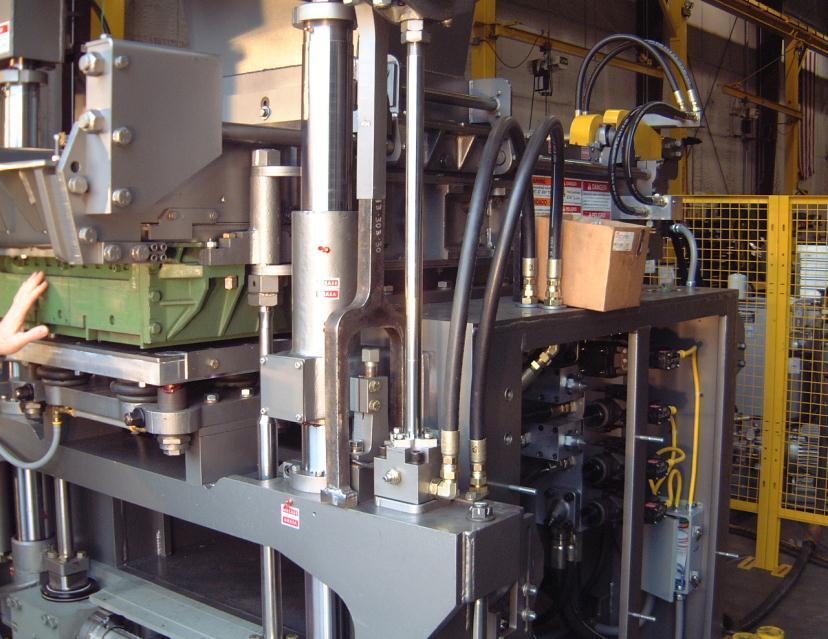
2 INSTALLATION PROCEDURES FOR STRIPPER AND COMPRESSION CYLINDERS FOR FLOOR LEVEL MACHINES MODEL 22, 16 AND 1600 Safety First: Always follow your safety guidelines for system lockout/tagout of electrical panels and the hydraulic system. The proper installation for stripper and compression cylinders is very important to ensure good life of the cylinders and their components. It is also important to check the front end of your machine for front-to-back play and side-to-side play as this can lead to shorter life of your cylinders. Upon receiving your compression cylinders or stripper cylinders they should be checked for any damages that may have occurred during shipping. Check the bottoms of the stripper cylinders for nicks or scratches. If noticed, use a flat file single cut fine to remove nicks or scratches. Only remove raised area. Also check for rust at the bottom of the stripper cylinders or any additional rust on the rod ends of the stripper or compression cylinders due to water damages. If light rust is noticed on the bottom of the stripper cylinders, you should use either of the following two hand pads listed below: Hand pad made by 3M Scotch-Brite general purpose color (Maroon) or Bear-Tex made of non-woven nylon web perfect for hand cleaning general all purpose color (Gray) These pads will remove rust and oxidation, and will clean & polish with gentle action and no effect on dimensions. Once cleaned, if you re not installing them on the machine at this time and will be placing them in the store room, make sure that you coat the base and cylinder rods with a light coat of grease to protect the bare surfaces. Also make sure that either plastic plugs or O-ring plugs are installed in all ports. Please see pictures below for referencing:


3 Clean stripper cylinder base with Scotch-Brite or Bear-Tex hand pads. Using a flat fine tooth file remove any scratches or nicks raised areas only. Using a straight edge check cylinder base for flatness across in three areas: up, down, and diagonally. Check the base foot area of the machine box where the stripper cylinder will mount. Ensure that there are no scratches or nicks and that the surfaces are flat for mounting the cylinders. Make sure to clean all threaded holes thoroughly. Apply a small amount of anti-seize lubricant to the bolts or threaded holes.

4 Check machine base foot for flatness and that correct stripper beam stops are in good condition. Check dimensions from the top of the stripper beam or main beam top machined surface to the machine foot surface area on both sides to ensure the beam is level from side-to-side. If beam is off by more then 1/16 from side-to-side it may be necessary to make further inspections. For compression cylinders it is advised to check alignment of the compression beam in relation to the stripper beam to ensure beams are in alignment with one another. If compression beam is off by more then 1/16 inch from side-to-side corrections must be made before connecting cylinders. Corrections should be made or cylinder damages will occur.

5 Top of main box machined surface. You can also verify dimensions by using a straight edge on the top machined surface of the main box and measuring down to the top of the stripper beam. Again these dimensions should be within 1/16 inch from side-to-side. Front end alignment problems could be caused by worn main shafts, bushings, guide tubes, column brackets or stripper beam worn due to guide tube clamp rings not holding guide tubes tight in beam. Lower height stops set incorrectly causing beam to rack or possibly area were stops contact lower stripper beam. For information on adjustment, front end alignment and stripper beam repairs, contact Columbia Machine service department at for assistance. Stripper cylinder installation: Once you have confirmed the beam is level with the main machine box and the cylinder base and machine foot area is ok cleaned free of scratches or nicks threaded holes cleaned, you are ready to install your stripper cylinders. Make sure you have installed the hydraulic fittings in both the base and rod cap and install the hardened washer on the rod.


6 With stripper beam resting on lower beam stops install the cylinder on machine foot rest area and using anti-seize apply a small amount to either the new grade 8 bolts or threaded holes. Always use new bolts and lock washers when changing out cylinders. Make sure the hardened washer has been installed on the rod assembly. Install the bolts by hand, threading them down as far as possible. Using either a box end wrench or ratchet wrench, snug the bolts down in a cross hatch pattern watching the alignment of the rod to the stripper beam where the rod will pass through the beam. Using a torque wrench, tighten the bolts up to torque in three equal settings using a crosshatch pattern. For floor level machines model 22, 16 & 1600, the bolts are a 5/8-18 NF Grade 8 bolts. Full torque is 187 foot pounds lubed. With all bolts torqued to specs, the cylinder rod should pass through the beam without touching the sides of the beam. With the hydraulic hoses attached and the machine slow valve closed for slow operation, begin to raise the rod through the stripper beam making sure the rod does not touch the side of the beam as this can damage the rod seal or cause misalignment with the cylinder causing failure. If the rods move up through the beam without touching, continue to raise the cylinder until the beam is raised to full stroke. Place enough beam stops on the lower height stops and begin to lower the cylinder allowing the rod to disengage from the beam. Make sure the rod, again, is not touching the sides of the beam as it leaves the beam. In the event that the rod is being forced over either when it leaves the beam or will not enter the beam without forcing, back the bolts off at the base and try to move the cylinder over slightly taking up any gap between the holes in the base of the cylinder. Again using a crosshatch pattern begin torquing the bolts down in three equal settings. Once the cylinder has been aligned and the rod can pass through the beam in either the full up position or down position, you are ready to install the locknut on the rod. Torque the rod locknut to 600 foot pounds on a model 22, 16 or Columbia Parts has a new locknut that has more surface area locking against the main beam. The locknut part number is Hardened washer. New locknut.

7 With cylinder installed and air evacuated from the cylinder, raise beam up and down several times, watching both cylinders and beam for any binding or racking. If all works fine open, slow valve up and back cushions out 1 ½ turns. This is the initial setting. Again raise and lower the beam several times, watching for binding or racking and to make sure you have a good cushion at the end of stroke. Once testing has been completed, shut the system down, lock the pump out and apply a small bead of silicone around the base of the cylinder to the base of the machine foot. Once oil has reached operating temperature, you may need to adjust cushions for smooth cushioning at end of stroke or racking of the beam. Compression cylinder installation: When changing out a compression cylinder or stripper cylinder you should always try to figure out what may have caused the failure. Contamination to the hydraulic system due to parts failure or binding of the compression beam or stripper beam, worn or loose front end allowing the beams to move too much, breaking the rod assembly or damaging the rod seal or piston seals. What about the air stroke assembly? Does the air stroke assembly move freely? What s the condition of the guide rods, bottom support bar, bumper rubber, bushings air bags? Due to the costs of these parts and the lost production down time repairs, these questions should be answered as you could possibly lose another cylinder in a very short time.

8 Bottom support bar. Locknuts are Columbia manufactured as the threads must be true to the nut facing. The compression cylinder rod is attached to the compression beam through the air stroke assembly. These components must be in good condition and move freely. If binding occurs in the air stroke assembly, this could cause racking of the compression beam which could break the rod assembly or damage the cylinder seals along with other damages that may occur. Inspect these parts and replacement of worn or damage items should be done when replacing a compression cylinder. Prior to installing the cylinder into the stripper beam, install the hydraulic fittings and position them in the right orientation at the base of the cylinder. Clean the threaded holes out in the stripper beam and apply a small amount of anti-seize to the threads or on the bolt threads. Remove the shipping bolt and nut holding the rod cap and bottom plate together. Once removed, be careful not to allow the cylinder tube and cap to separate and slide the compression cylinder down into the stripper beam. Make sure that you position the cylinder so the rod cap porting is facing in the correct orientation to hook up the hoses. Install the (4) socket head bolts threading them into the stripper beam. Using a crosshatch pattern snug the bolts down, but do not torque at this time. Hook up the tube assembly at the base of the cylinder and hose at the rod cap.


9 Columbia manufactured jam nut & compression cylinder rod end. In the picture above you will notice that the compression rod has a nipple at the threaded end of the rod. When threading the rod into the air stroke assembly bottom support bar, it must be bottom out in the support bar. This ensures that the mating threads of the rod and support bar are seated. Never adjust the cylinder rod out to correct any racking of the beam. The rod must be bottomed out in the support bar. Always use Columbia Machine special jam nuts as they are manufactured with the threads true to the facing. Standard jam nuts are not true 90 degrees to the face. Cylinder rod breakage can occur if not using the Columbia manufactured jam nuts. With bolts installed and hydraulic hoses and tubes hooked up, you are ready to align the rod to the air stroke assembly. As we discussed for stripper cylinder installation, please follow the same procedures for checking beam alignment. Once you have confirmed that the stripper beam is level, true to the block machine main box and you have checked from the top of the stripper beam to the bottom machined surface of the compression beam and both sides are within 1/16 from side-to-side, you can begin to torque the bolts using a crosshatch pattern. Torque the cylinder down to the stripper beam using three equal torque settings. For model 22 socket head cap screw ½ -13 UNC torque to 70 to 80 foot pounds max. Model 16 and 1600 floor level machine 5/8 11 UNC torque to 90 to 100 foot pounds max.
10 As you are torquing the bolts, watch the rod move around at the top. When you get to your final torque setting, the rod should be aligned with the bottom retainer bar threaded hole. With the jam nuts installed on the rod, run them down to the bottom of the threads and lock them together. Apply anti-seize to the threads. Check to make sure the hydraulic connections are tight. Remove your locks from the pump and main panel making sure the machine slow valve is set for slow operation. Turn the pump on and raise the cylinders just enough so that the nipple of the rod enters the bottom retainer bar. Turn the pump off and lock out the system. Turn the air off the head air bags. With the air off, the air stroke assembly should drop down slightly when the air is evacuated from the air bags. This will allow you to start threading the rod into the bottom retainer bar by hand or with the use of an open end wrench. You should not have to force the rod in or push the rod from side-to-side to start threading the rod in. If you have aligned the rod correctly when you were torquing the cylinder bolts down to the stripper beam you should be able to thread the rod into the bottom retainer bar. Once the rod is bottomed out give a couple hard jerks with the wrench to set the rod tight into the retainer bar. Break the jam nuts loose and tighten each one against the retainer bar and jam nut. On some compression cylinders, rather then a built in cushion on the rod end cap, we have adjustable cushions installed. For initial settings screw the adjusting screw in clockwise until it bottoms out and back out 1 ½ turns. During setup you may need to adjust one side more then the other to eliminate beam racking from side-to-side. Once the oil has warmed to operating temperature you may need to adjust the cushions a little more. Screwing the cushion in clockwise increases cushion out and counter clockwise decreases cushion. Adjust cushions so that the beam does not bang hard at the end of stroke when going up and eliminate side racking of the beam.

11 Cushion adjustment. NOTE: A gap must be maintained to properly seal rod cap to tube assembly. Over tightening will result in damage to the tube flag. With the cylinder or cylinders installed you, are ready to make your final settings. Remove locks from system and start pump. Again keeping the slow valve in position for slow operation raise and lower compression beam several times watching for any leaks. Turn head air back on. Place the slow valve in fast operation and run the compression beam up and down. Make sure the stripper beam is in the up position so that full stroke of the cylinder is made. Check for side to side racking of the beam and make adjustments to the cushions. Also adjust cushions just enough so that you have a good cushion at end of stroke going up without the beam banging at end of stroke. Check the down stroke for racking as well. If the beam lags behind on the right side as you begin to start down, back out the cushion slightly. Run the beam up and down several more times. Once the beam can travel to its full up position and down position without racking or banging, you have completed the adjustments. Remember, once the oil warms up to operating temperature, it may be necessary to make adjustments to the cushions again.
12 With both compression and stripper beams in the down position, turn the power off and lock out the system. As an added protection to keep contamination from getting into the threads where the cylinders have been bolted down, it is suggested to apply a small amount of silicone around the base of the cylinders and lock washers. This will aid in keeping the bolts and threads clean from contamination. This completes the stripper and compression cylinder installation. For additional information or service help, please call Columbia Machine Inc. at Please review information below for Safety Beam Stops application for compression beam and stripper beam for added safety during mold changes, adjustments and repairs.


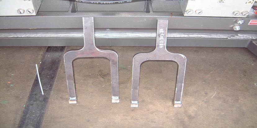
13 SAFETY BEAM STOPS COMPRESSION BEAM STOPS FOR FLOOR LEVEL MACHINES MODEL 22, 16 AND 1600 Safety first: Always follow your safety guidelines for system lockout/tagout of electrical panels and the hydraulic system. The installation and use of the new compression beam stops is to maintain compression beam up during mold change, feed drawer strike off plate adjustment or additional repairs or adjustments that require plant personnel to be working in and around the machine with the beam in the up position. The hydraulic circuit for the compression beam on some machines has a P.O. check valve and on others you have a P.O. counterbalance valve. Both these style check valves hold pressure on the base end of the compression cylinder until the valve is energized down which uses pilot pressure to open the check valve or counterbalance valve. In the event that one or both compression cylinders are allowing hydraulic oil to bypass the piston seals the beam will drift down slowly or fast depending on the condition of the seals. Other hydraulic failures can cause the beam to not stay up which could include failure to the P.O. Check valve or P.O. counterbalance valve. The beam stops are a positive stop between the compression beam and stripper beam which in the event that either loss of hydraulics, failure to the compression cylinder or P.O. check valve, P.O. counterbalance valve the beam stops will maintain beam in up position. The following pictures below show the installation of these new positive beam stops: (more pictures next page)
14


15 LOWER STRIPPER BEAM STOPS FOR FLOOR LEVEL MACHINES MODEL 22, 16 AND 1600 In addition for mold installation, adjustments or repairs use your lower stripper beam stops to aid in holding the stripper beam in the up position install additional stops as required. The stripper hydraulic circuit also has either a P.O. check Valve or P.O. counterbalance valve that maintains hydraulic oil to the base of the cylinders. The same failures can occur on the stripper circuit as with the compression beam. The mechanical stops are an added safety for maintaining the beam in the up position during mold changes, cylinder replacements, vibrator & shaker shaft repairs or replacement where you will be required to have your hands in and under the beams. Please see pictured below stripper beam stops: Use additional stops as required during mold changes, adjustments or repairs. For more information or to order a set of beam stops please contact Columbia Machine, Inc. parts department
Mixer Discharge Door Adjustment on models; 30, 42, 54, 81, 108, 135 mixers.
 Knowledge Base Article Type: Instructions Mixer Discharge Door Adjustment on models; 30, 42, 54, 81, 108, 135 mixers. Description: Instructions on How to set-up and adjust the discharge door on Columbia
Clutch Installation Guide
 Clutch Installation Guide 0 STOP! READ CAREFULLY BEFORE INSTALLING CLUTCH This clutch must be installed by a qualified installer. Improper installation or failure to replace or resurface the flywheel,
STAINLESS STEEL SERIES LSSW HIGH PRESSURE HYDRAULIC CYLINDERS INSTALLATION & OPERATING INSTRUCTIONS
 CATALOG: LSSW-00 STAINLESS STEEL SERIES LSSW HIGH PRESSURE HYDRAULIC CYLINDERS INSTALLATION & OPERATING INSTRUCTIONS REMEMBER.... WHEN PERFORMANCE COUNTS SPECIFY LEHIGH LEHIGH FLUID POWER, INC. 1413 ROUTE
Self-Adjust Clutch Installation Guide
 Self-Adjust Clutch Installation Guide 0 STOP! READ CAREFULLY BEFORE INSTALLING CLUTCH This clutch must be installed by a qualified installer. Improper installation or failure to replace or resurface the
Model DFR 070/156/220 Rotary Actuator
 Figure 1 DFR 156 TABLE OF CONTENTS General 2 Actuator Assembly 18 Scope 2 Bushing / Yoke Assembly 18 Principles of Operation 2 Spring Barrel Assembly 18 Safety Caution 2 Diaphragm Plate Assembly 20 Specifications
Next, chase the threads in the lower A-arm mounts with the 5/8-18 tap and blowout any remaining particles.
 Next, chase the threads in the lower A-arm mounts with the 5/8-18 tap and blowout any remaining particles. Now, apply some anti-seize to the threads of the pivot stud. Also put anti-seize inside the bore
Ford 8, 9 Small Bearing Installation Instructions Rear Disc Conversion
 Ford 8, 9 Small Bearing Installation Instructions Rear Disc Conversion This kit is for Ford 9 rear axles with the small (2.835 ) style bearing and Ford 8 rear ends. This kit is designed to work with axles
Instruction Manual for HSPA Take-Up Units
 Installation Instruction Manual for HSPA Take-Up Units Warning: To ensure the drive is not unexpectedly started, turn off and lockout the power source before proceeding. Failure to observe these precautions
Warning and Safety Precautions
 EXPRESS WARRANTY AND DISCLAIMER OF IMPLIED WARRANTIES Lily Corporation unconditionally guarantees its products to be free of defects in material or workmanship and further warrants that, for a period of
Mopar 8 3/4 & 9 3/4 (Dana) Installation Instructions Rear Disc Conversion
 Installation Instructions Rear Disc Conversion") Mopar 8 3/4 & 9 3/4 (Dana) Installation Instructions Rear Disc Conversion This kit is for either Mopar 8 ¾ or Mopar 9 ¾ (Dana). This kit is designed to work with axles with either GM 5 x 4.75 Bolt Pattern
Mopar 8 3/4 & 9 3/4 (Dana) Installation Instructions Rear Disc Conversion This kit is for either Mopar 8 ¾ or Mopar 9 ¾ (Dana). This kit is designed to work with axles with either GM 5 x 4.75 Bolt Pattern
Remote Temperature Controller for Heated Mold Shoes, using a RTD/Digital Display, # C (version pre-2009).
.") Knowledge Base Article Type: Instructions Remote Temperature Controller for Heated Mold Shoes, using a RTD/Digital Display, #601127.C (version pre-2009). Description: Instructions on How to properly set-up
Knowledge Base Article Type: Instructions Remote Temperature Controller for Heated Mold Shoes, using a RTD/Digital Display, #601127.C (version pre-2009). Description: Instructions on How to properly set-up
Wheel Angle Sensor Kit Installation
 Wheel Angle Sensor Kit Installation Item Component Part Number Qty 1. WAS Bracket Kit 200-0247-02 1 2. WAS Assembly Kit 200-0468-01 1 3. Instruction Guide 602-0401-01 1 602-0401-01-A Overview Always shut
WHIRLWIND. Owner s Manual Series (Rev ) Serial Number: Manufacture Date: A V I A T I O N Model: WHIRL WIND AVIATION
 Serial Number: Manufacture Date: A V I A T I O N Model: WHIRL WIND AVIATION") WHIRLWIND A V I A T I O N Model: 100-4 Serial Number: 100-4- Manufacture Date: M a nufacturer of Composite Constant Speed P r o pellers Owner s Manual 100-4 Series (Rev 2014-2) WHIRL WIND AVIATION 1419
WHIRLWIND A V I A T I O N Model: 100-4 Serial Number: 100-4- Manufacture Date: M a nufacturer of Composite Constant Speed P r o pellers Owner s Manual 100-4 Series (Rev 2014-2) WHIRL WIND AVIATION 1419
Clutch Kit Install Guide
 Jack up and support the car on jack stands Remove the exhaust system (some models) Remove the driveshaft (rear wheel drive) Remove CV axle (front wheel drive) Manual transmission removal Clutch Kit Install
WHIRLWIND. Owner s Manual 151H Series (Rev ) Model: 151H Serial Number: Manufacture Date: A V I A T I O N WHIRL WIND AVIATION
 Model: 151H Serial Number: Manufacture Date: A V I A T I O N WHIRL WIND AVIATION") WHIRLWIND A V I A T I O N M a nufacturer of Composite Constant Speed P r o pellers Model: 151H Serial Number: Manufacture Date: Owner s Manual 151H Series (Rev 2014-2) WHIRL WIND AVIATION 1419 STATE ROUTE
WHIRLWIND A V I A T I O N M a nufacturer of Composite Constant Speed P r o pellers Model: 151H Serial Number: Manufacture Date: Owner s Manual 151H Series (Rev 2014-2) WHIRL WIND AVIATION 1419 STATE ROUTE
Assembly Manual. 1/10th Formula 1 Car
 Assembly Manual 1/10th Formula 1 Car Center Pivot Bag 1 3374 - Center Pivot Socket 40194 - Hard Anodized Alum Pivot ball 3254-2-56 *Note - Sometimes it is helpful to slightly over-tighten the top clamp
16K ORBITAL ROTATING RUBBER PIN BOX *
 16K ORBITAL ROTATING RUBBER PIN BOX * OPERATING INSTRUCTIONS AND OWNER S MANUAL * Patented Congratulations on the purchase of the MORryde 16k Orbital Rotating Rubber Pin Box. This revolutionary new system
INSTALLATION GUIDE Bolt-On Drag-Race Strut Clip Chevy II
 INSTALLATION GUIDE 7702 Bolt-On Drag-Race Strut Clip 1962-67 Chevy II Description: STRUT CLIP 4130 BOLT ON 62-67 CHEVY II, INCLUDES 4130 ROUND TUBE FRAME CLIP, DOUBLE-ADJUSTABLE STRUTS, ADJUSTABLE-HEIGHT
Please contact BrakeAway Products tech support for additional (503) or
 or") Congratulations on the purchase of your new BrakeAway Motorcycle Cruise Control. At BrakeAway Products, we are committed to your complete satisfaction. With proper installation, use, and periodic maintenance,
Congratulations on the purchase of your new BrakeAway Motorcycle Cruise Control. At BrakeAway Products, we are committed to your complete satisfaction. With proper installation, use, and periodic maintenance,
Tech Note Truck 14 & 15.5 Twin Plate Cast Iron Type Installation Guidelines
 1. (14 & 15.5 ) Check condition of the flywheel. Grind to resurface or replace flywheel. Surface MUST BE machined or premature clutch failure can occur. Flywheel depth must be 2.938 (74.62mm) for 14 (350mm)
INSTRUCTION MANUAL INSTALLING NEW GREASE IN UT SERIES PNEUMATIC ACTUATOR
 INSTRUCTION MANUAL INSTALLING NEW GREASE IN UT SERIES PNEUMATIC ACTUATOR This instruction manual explains the steps required to degrease and install new grease into the Max-Air UT series pneumatic actuator.
Kysor On/Off Rear Air Fan Drive
 . Proper precautions must be taken to prevent personal injury from contact with moving parts, unintended engine start or other hazards present when working with powered equipment. Refer to the vehicle
Shown on model Bolts 6 Oil lines 5 Screw 7 Adjusting screw Shown on model 209
 AR46.20-P-0003Q Replace bottom radial shaft sealing ring on control head 4.5.07 MODEL 203, 209 except CODE (213) Speed-sensitive power steering MODEL 215, 220 Shown on model 209 1 Clamps 2 Bellows 3 Inner
HYDRAULIC PALLET TRUCK MODEL NO: PT540M/BM/CM & PT685BM/CM PART NO: , , , ,
 HYDRAULIC PALLET TRUCK MODEL NO: PT540M/BM/CM & PT685BM/CM PART NO: 7631700, 7631705, 7631710, 7631715, 7631720 OPERATION & MAINTENANCE INSTRUCTIONS LS0316 INTRODUCTION Thank you for purchasing this CLARKE
THE Hydralift KIT TOOLS NEEDED
 OPERATION MANUAL TOOLS NEEDED Hydralift Kit (Hydralift, Hydraulic Pump with Charged Batteries, 3, 6, and 9 Spacer, Hydrastick, Hose Assembly), Torque Wrench with 1.25 Socket, 3-bolt Polished Rod Clamp
55-64 Full Size GM (Impala, Bel Air, etc.) This kit is for axles with a 3 3/8 spread center to center on the top two bolt holes (pictured left).
 This kit is for axles with a 3 3/8 spread center to center on the top two bolt holes (pictured left).") SUM-BK1624A Full Size GM Installation Instructions Rear Disc Conversion 55-64 Full Size GM (Impala, Bel Air, etc.) This kit is for axles with a 3 3/8 spread center to center on the top two bolt holes (pictured
SUM-BK1624A Full Size GM Installation Instructions Rear Disc Conversion 55-64 Full Size GM (Impala, Bel Air, etc.) This kit is for axles with a 3 3/8 spread center to center on the top two bolt holes (pictured
Fisher 657 Diaphragm Actuator Sizes and 87
 Instruction Manual 657 Actuator (30-70 and 87) Fisher 657 Diaphragm Actuator Sizes 30 70 and 87 Contents Introduction... 1 Scope of Manual... 1 Description... 2 Specifications... 2 Installation... 3 Mounting
A /F/X Body Instruction Packet Rear Disc Conversion
 A /F/X Body Instruction Packet Rear Disc Conversion 64-72 A Body / 67-81 F Body / 62-74 X Body This kit is for axles with a 3 1/8 spread center to center on the top two bolt holes (pictured left). Rotor
Original. User Manual & Install Guide. Safe-T-Pull Inc. Page 1 of 15
 Original User Manual & Install Guide Safe-T-Pull Inc. Page 1 of 15 TABLE OF CONTINENTS 1. Before You Begin...3 Disclaimer...3 What Is Included...3 Claims...3 Contact Us...4 Safety Notes...4 2. Introduction...5
UNIFLO Control Valve
 Severe Service Control Valves MAINTENANCE AND INSTRUCTION MANUAL UNIFLO Control Valve The Problem Solver TM BOTTOM COVER DESIGN DFT INC. 2 www.dft-valves.com DFT INC. 3 www.dft-valves.com WARNING: USER
Eliminator Vented Disc Brakes Owners Manual
 Eliminator Vented Disc Brakes Owners Manual TIE DOWN ENGINEERING 255 Villanova Drive SW, Atlanta, GA 30336 www.tiedown.com (404) 344-0000 Fax (404) 349-0401 2008 TIE DOWN INC. ALL RIGHTS RESERVED Instruction
ANDERSON GREENWOOD SERIES 500 PILOT OPERATED SAFETY RELIEF VALVES INSTALLATION AND MAINTENANCE INSTRUCTIONS
 Before installation these instructions must be fully read and understood TABLE OF CONTENTS 1. General valve description and start-up... 1 2. Main valve maintenance... 1 3. Pilot maintenance... 5 4. Pilot
Sofa Slideout Assembly OWNER'S MANUAL. Rev: Page 1 Sofa Slideout Owners Manual
 Sofa Slideout Assembly OWNER'S MANUAL Rev: 06.14.2016 Page 1 Sofa Slideout Owners Manual TABLE OF CONTENTS Warning, Safety, and System Requirement Information 3 Product Information 3 Prior to Operation
Firehawk Responder Second Stage Regulator
 Firehawk Responder Second Stage Regulator MAINTENANCE AND REPAIR MSA 511 (L) Rev. 4 MSA 2015 Prnt. Spec. 10000005389(I) Mat. 10096394 Doc. 10096394 Replacement Kits and Overhaul Kit P/N Description Firehawk
SuperTrac. Axle. Service & Maintenance. Manual
 SuperTrac Axle Service & Maintenance Manual Table of Contents Page Exploded Views Section 1: General Information General Warnings Description of Axle Models Identifications Section 2: Installation Axle
Sub Section Title Page No.
 Sub Section Title Page No. 1 Introduction 3 2 Routine Maintenance 3 3 Disassembly 4 3.1 Disassembly of Double Crank Design 4 3.2 Disassembly of Scotch Yoke Design 5 3.3 Disassembly of Actuator Cylinder
INSTRUCTIONS FOR MODELS # 2200/#2400
 --- WARNING --- 1. A hot stamping press applies high pressure with heat to the article being marked. Care should be taken by the operator to keep hands free of the stamping area whenever the equipment
M52tu-M54 VANOS Assembly & Timing Using G.A.S. Professional Cam Tool Kit
 Home BMW Solutions Porsche Solutions DIY Tech Engine Services Dyno Services Machining About Contact Store Tool Rental M52tu-M54 VANOS Assembly & Timing Using G.A.S. Professional Cam Tool Kit This procedure
Bag 1. Bag 1. Center Pivot. Center Pivot
 8 00734 01901 5 Center Pivot Bag 1 3374 - Center Pivot Socket 4019 - Alum Pivot ball 3254-2-56 Button Head *Note - Sometimes it is helpful to slightly over-tighten the top clamp screws, then work the ball
DeZURIK R1 AND R2 POWERRAC ACTUATORS
 R1 AND R2 POWERRAC ACTUATORS Instruction D10268 July 2016 Instructions These instructions provide installation, operation, and maintenance information for R1 AND R2 POWERRAC Actuators. They include procedures
HORSTMAN GREASED LIGHTNING CLUTCH
 HORSTMAN GREASED LIGHTNING CLUTCH Horstman s Greased Lightning (GL) clutch is designed for ultra high performance, and requires expert setup and a serious commitment to maintenance. Warning!!! 1. Clutch
Service Manual Gulf Stream Electronic Full Wall Slide Systems
 Service Manual Gulf Stream Electronic Full Wall Slide Systems CONTENTS Page Before you operate the slide system 2 Operating Instructions 3 Preventive maintenance 3 Manually overriding your slide system
Instant Chat off the main page of Or simply call our tech team at
 Adjustable Fuel Pressure Regulator Kit for 2008+STI 2018-10-03 PSP-FUL-301 Thank you for purchasing this PERRIN product for your car! Installation of this product should only be performed by persons experienced
LOW PRESSURE BALANCED VALVE DIAPHRAGM BALANCED
 DIAPHRAGM BALANCED All Rights Reserved. All contents of this publication including illustrations are believed to be reliable. And while efforts have been made to ensure their accuracy, they are not to
SAFARI Helicopter Flight Control Rigging Manual Revision 9 4/3/2010 CHR International Inc.
 SAFARI Helicopter Flight Control Rigging Manual Revision 9 4/3/2010 CHR International Inc. The following procedures are meant as a guide to assist you in the safe configuration of your helicopter s Flight
I-795/906. Series 795 and 906 Installation-Ready Knife Gate Valves WARNING INSTALLATION AND MAINTENANCE INSTRUCTIONS
 INSTALLATION AND MAINTENANCE INSTRUCTIONS I-795/906 Series 795 and 906 Installation-Ready Knife Gate Valves HANDWHEEL OPERATOR PNEUMATIC OPERATOR HYDRAULIC OPERATOR WARNING Read and understand all instructions
RELEASING PRESSURE IN THE HYDRAULIC SYSTEM,
 Testing And Adjusting Introduction NOTE: For Specifications with illustrations, make reference to SPECIFICATIONS for 225 EXCAVATOR HYDRAULIC SYSTEM, Form No. SENR7734. If the Specifications are not the
Modular Engine 1, 2008 revision August 3, 2008
 Modular Engine 1, 2008 revision August 3, 2008 David Kerzel 2008 Back in 2002 I wanted to build a bunch of different engines without a lot of detail to learn how to build an engine, what works and what
1. WARNINGS 3. DAILY INSPECTION
 Thank you for using this lift table. Your lift table is made of high quality steel and is designed for the horizontal lifting and transport of loads on a level, fixed base. For your safety and correct
CALIFORNIA TRIMMER MOWER MAINTENANCE MANUAL
 CALIFORNIA TRIMMER MOWER MAINTENANCE MANUAL 2 Table of Contents Section 1: General Information Page Handle Assembly Instructions 4 Maintenance All Models 6 Oil Change Procedures All Models 9 Height Adjustment
INSTALLATION GUIDE TCP RCKM-01
 READ ALL INSTRUCTIONS COMPLETELY AND THOROUGHLY UNDERSTAND THEM BEFORE DOING ANYTHING. CALL TOTAL CONTROL PRODUCTS TECH SUPPORT (916) 388-0288 IF YOU NEED ASSISTANCE. INSTALLATION GUIDE TCP RCKM-01 Manual
BUCKET SWEEPER OPERATORS & PARTS MANUAL 2852 & 3174 SERIES
 OM628 BUCKET SWEEPER OPERATORS & PARTS MANUAL 2852 & 3174 SERIES MODEL 12002-5 FOOT WIDE X 24 INCH DIAMETER (SKID-STEER) MODEL 12004-6 FOOT WIDE X 24 INCH DIAMETER (SKID-STEER) MODEL 12017-6 FOOT WIDE
Failure Diagnosis. The LuK guide to troubleshooting clutch system failures and malfunctions on agricultural vehicles
 Failure Diagnosis The LuK guide to troubleshooting clutch system failures and malfunctions on agricultural vehicles Contents Page Failure diagnosis / causes of failures Clutch fault diagnosis What is clutch
Tooling Assistance Center
 Safeguards are designed into this application equipment to protect operators and maintenance personnel from most hazards during equipment operation. However, certain safety precautions must be taken by
Purging Air From Divider Block Lubrication Systems
 FROST ENGINEERING SERVICE Purging Air From Lubrication Systems A D I V I S I O N O F G E C S E Y S A L E S & S E R V I C E DESCRIPTION Divider block lubrication systems operate correctly only when all
Page 1. File: Motolight caliper one-piece Harley Date: 8/15/2006
 Page 1 Harley-Davidson FL Caliper Mount Installation One-piece mounting brackets You should allow about two to three hours for installation. We suggest you use a well-lighted space for installation. PLEASE
Installation Manual TWM Performance Short Shifter Cobalt SS/SC, SS/TC, HHR SS, Ion Redline and Saab 9-3
 Page 1 Installation Manual TWM Performance Short Shifter Cobalt SS/SC, SS/TC, HHR SS, Ion Redline and Saab 9-3 Please Note: It is preferable to park on a flat surface, as you will have to engage and disengage
Fisher 1051 and 1052 Style H and J Sizes 40, 60 and 70 Rotary Actuators
 Instruction Manual 1051 and 1052 H & J Actuators Fisher 1051 and 1052 Style H and J Sizes 40, 60 and 70 Rotary Actuators Contents Introduction... 1 Scope of Manual... 1 Description... 2 Specifications...
INSTRUCTIONS CONTINUED AIRWORTHINESS
 INSTRUCTIONS FOR CONTINUED AIRWORTHINESS FOR GROVE MAIN WHEEL AND BRAKE ASSEMBLIES WITH FAA-TSO APPROVAL DOCUMENT 13046-11 Rev C April 29, 2018 TABLE OF CONTENTS SECTION PAGE Title Page... 1 Table of Contents...
INSTALLATION GUIDE STAINLESS DRAG-RACE STEERING COLUMN
 INSTALLATION GUIDE STAINLESS DRAG-RACE STEERING COLUMN Description: STEERING COLUMN STAINLESS TUBE x 4 LONG, DUAL /4- SPLINE /4 x 48 TUBULAR COLUMN SHAFTS, BILLET MOUNTS, DUAL ALUMINUM U-JOINTS & QUICK
Important: Please read these instructions carefully and completely before starting the installation. TITAN Fuel Tanks
 TITAN pt. no.: 01 0000 0129 Important: Please read these instructions carefully and completely before starting the installation. TITAN Fuel Tanks INSTALLATION INSTRUCTIONS G e n e r a t i o n V Extended
Parts List See cover Page
 Thank you for purchasing the CorkSport Front Mount Intercooler Kit for the 2010-2013 Mazdaspeed 3. Keep your BAT s under check with the CorkSport FMIC Kit with the small or large intercooler. Please let
Temperature Sensor Series
 GENERAL DESCRIPTION The patented* No. 85026-Series Temperature Sensor contains a two-position valve operated by temperature variations around the integral sensing bulb. It is used to vent or block a pneumatic
CORPORATION REPAIR MANUAL HWH SPACEMAKER ROOM EXTENSION SYSTEM NO LEVELING SYSTEM FOR NATIONAL RV NON-MOTORIZED VEHICLES
 HWH R CORPORATION REPAIR MANUAL HWH SPACEMAKER SYSTEM NO LEVELING SYSTEM FOR NATIONAL RV NON-MOTORIZED VEHICLES FEATURING: DUAL CYLINDER "RAIL" (WITH RACK SENSING VALVE) SINGLE CYLINDER DUAL CYLINDER "RAIL"
RolsplicerTM. Maintenance Manual And Illustrated Parts List
 RolsplicerTM Maintenance Manual And Illustrated Parts List List of Illustrations Figure Page. Rolsplicer 3 2. Roller Adjustment 4 3. Rolsplicer 6 4. Lid Hold Down Assembly 8 5. Automatic Lid Speed Adjustment
INSTRUCTION INFORMATION FOR TYPE "DB" ELECTRIC DISC BRAKE (DB-0, DB-2, DB-4)
") The Last Word in Cranes INSTRUCTION INFORMATION FOR TYPE "DB" ELECTRIC DISC BRAKE (DB-0, DB-2, DB-4) OPERATION Zenar's type "DB" brakes are classified as a holding or parking type electro-mechanical operated
The Last Word in Cranes INSTRUCTION INFORMATION FOR TYPE "DB" ELECTRIC DISC BRAKE (DB-0, DB-2, DB-4) OPERATION Zenar's type "DB" brakes are classified as a holding or parking type electro-mechanical operated
Multistrada (MTS) Tank Installation Notes. Tools Required. Phase 1: Remove Fairings. Phase 2: Remove Fuel Tank
 Tank Installation Notes. Tools Required. Phase 1: Remove Fairings. Phase 2: Remove Fuel Tank") The California Cycleworks MTS tank provides an aftermarket alternative to the OEM nylon fuel tanks as used on aircooled Desmodue Ducati Multistrada 1100, 1000, and 620 models. This fuel tank is NOT for
The California Cycleworks MTS tank provides an aftermarket alternative to the OEM nylon fuel tanks as used on aircooled Desmodue Ducati Multistrada 1100, 1000, and 620 models. This fuel tank is NOT for
INSTALLATION GUIDE. TCP STRD-07 Adjustable Strut Rods
 READ ALL INSTRUCTIONS COMPLETELY AND THOROUGHLY UNDERSTAND THEM BEFORE DOING ANYTHING. CALL TOTAL CONTROL PRODUCTS TECH SUPPORT (916) 388-0288 IF YOU NEED ASSISTANCE. INSTALLATION GUIDE TCP STRD-07 Adjustable
COMPETITION ENGINEERING. 80 Carter Drive P.O. Box 1470 Guilford, CT Phone: (203) Fax: (203)
 Fax: (203)") INSTALLATION INSTRUCTIONS P/N: C2094 SLIDE-A-LINK The Slide-A-Link by Competition Engineering is designed for use in Stock Eliminator and Bracket Racing vehicles. The rigid front mount assembly clamps
INSTALLATION INSTRUCTIONS P/N: C2094 SLIDE-A-LINK The Slide-A-Link by Competition Engineering is designed for use in Stock Eliminator and Bracket Racing vehicles. The rigid front mount assembly clamps
B&W Trailer Hitches 1216 Hawaii Road / PO Box 186 Humboldt, KS P: F:
 B&W Trailer Hitches 1216 Hawaii Road / PO Box 186 Humboldt, KS 66748 P:620.473.3664 F:620.869.9031 NOTE: We recommend reading instructions before beginning the installation. Ford OEM Mount System Slider
<THESE INSTRUCTIONS MUST BE GIVEN TO THE END USER> B&W Trailer Hitches 1216 Hawaii Road / PO Box 186 Humboldt, KS P: F:
 B&W Trailer Hitches 26 Hawaii Road / PO Box 86 Humboldt, KS 6678 P:620.73.366 F:620.869.903 RAM OEM Mount System Installation Instructions 25,000 LBS.
Embedded Rack Slide-out System
 Embedded Rack Slide-out System SERVICE MANUAL Rev: 02.16.2017 Page 1 Electric Embedded Rack Slide-out System TABLE OF CONTENTS Safety Information 3 Product Information 3 Operation 4 Extending Slide-Out
Important: Please read these instructions carefully and completely before starting the installation. TITAN Fuel Tanks
 TITAN pt. no.: 01 0000 0119 Important: Please read these instructions carefully and completely before starting the installation. TITAN Fuel Tanks INSTALLATION INSTRUCTIONS G e n e r a t i o n V Extended
Air-Assist Service Jack Max. Capacity: 10 Tons
 Form No. 565786 Parts List & Operating Instructions for: 1511B Air-Assist Service Jack Max. Capacity: 10 Tons 109 67 66 68 77 69 70 78 95 94 107 106 108 26 71 72 72 93 X L 65 75 92 91 90 89 88 87 86 85
B&W Trailer Hitches 1216 Hawaii Road / PO Box 186 Humboldt, KS P: F: " Split Lock Washers 8
 B&W Trailer Hitches 1216 Hawaii Road / PO Box 186 Humboldt, KS 66748 P:620.473.3664 F:620.869.9031 NOTE: We recommend reading instructions before beginning the installation. Companion Slider Hitch Installation
CENTERLINE 2100 Motor Control Centers 600A, 800A, and 1200A Bolted Pressure Contact Switch
 Instructions CENTERLINE 2100 Motor Control Centers 600A, 800A, and 1200A Bolted Pressure Contact Switch CENTERLINE 2100 Motor Control Centers Introduction The intent of this publication is to provide field
DeZURIK SPRING RETURN CYLINDER OPERATOR FOR G-SERIES ACTUATORS USED ON PEF 100% PORT ECCENTRIC VALVES
 SPRING RETURN CYLINDER OPERATOR FOR G-SERIES ACTUATORS USED ON PEF 100% PORT ECCENTRIC VALVES Instruction D10466 December 2012 Instructions These instructions provide information about s. They are for
Model DF233 Control Valve
 Figure 1 DF233 Control Valve TABLE OF CONTENTS Introduction 2 Body and Packing Reassembly 7 Specifications 3 Fail Closed Actuator Reassembly 8 Valve Sizes 3 Fail Open Actuator Reassembly 9 Unpacking 4
Timing belt change. Timing belt change
 Timing belt change Put 2 new Gates T275 timing belts on today. Tensioner drilled smooth and tight with less than 16,000 miles on her decided not to change the tensioners just the belts. You'll need some
Contents. Section 5: Adjustments Ball Detect Adjustment Transport Band Tension Adjustment
 Contents Section 5: Adjustments... 5-3 1. Ball Detect Adjustment... 5-3 2. Transport Band Tension Adjustment... 5-5 3. Transport Band Drive Belt Tension Adjustment... 5-7 4. Ball Cushion Adjustment...
servicing the swivel
 servicing the swivel The swivel seals and bearings require periodic replacement. This document describes how to determine which service procedure to use to service the swivel assembly, part number 101110.
Model DF269 Control Valve
 Figure 1 DF269 Control Valve TABLE OF CONTENTS Introduction 2 Fail Open Actuator Disassembly 6 General 2 Body and Packing Reassembly 7 Scope 2 Fail Closed Actuator Resassembly 8 Specifications 3 Fail Open
270PK SERVICE GUIDELINES
 270 Coupling THE FIRST NAME IN QUALITY COUPLINGS 270PK SERVICE GUIDELINES BEFORE GETTING STARTED: This procedure should only be performed by a qualified mechanic. Measure the wear on the coupling s pintle
Model 3400 ATTENTION: WARNING
 B&W Trailer Hitches 1216 Hawaii Road / PO Box 186 Humboldt, KS 66748 P:620.473.3664 F:620.473.3766 NOTE: We recommend reading instructions before beginning the installation. Companion Slider Hitch Installation
Wheel Angle Sensor Kit Installation
 Wheel Angle Sensor Kit Installation Item Component Part Number Qty 1. Bracket Kit, WAS 200-0572-01 1 2. WAS Assembly 200-0468-01 1 3. Instruction Guide 602-0456-01 1 602-0456-01-A Overview Always shut
CAUTION: The possible problems and causes are listed in order of likelihood and ease of checking.
 The information contained herein is for use by skilled hydraulic elevator professionals. Before disassembly of the valve, make sure the power is off by turning the main disconnect switch off and that the
<THESE INSTRUCTIONS MUST BE GIVEN TO THE END USER> B&W Trailer Hitches 1216 Hawaii Road / PO Box 186 Humboldt, KS P: F:
 B&W Trailer Hitches 26 Hawaii Road / PO Box 86 Humboldt, KS 6678 P:620.73.366 F:620.869.903 Ford OEM Mount System Installation Instructions 20,000 LBS.
B&W Trailer Hitches 1216 Hawaii Road / PO Box 186 Humboldt, KS P: F:
 B&W Trailer Hitches 1216 Hawaii Road / PO Box 186 Humboldt, KS 66748 P:620.473.3664 F:620.473.3766 NOTE: We recommend reading instructions before beginning the installation. GM OEM Mount System Slider
Superior Wheel Installation Guide (No Turbo removal)
") Superior Wheel Installation Guide (No Turbo removal) This is the process used to install the Turbo Wheel without having to remove the Turbo from your Engine. It should take a maximum of 5 hours. Tools:
Superior Wheel Installation Guide (No Turbo removal) This is the process used to install the Turbo Wheel without having to remove the Turbo from your Engine. It should take a maximum of 5 hours. Tools:
RIGID SERIES REAR BUMPER RB-F-100-JK, RB-F-101-JK, RB-F-102-JK, RB-F-103-JK RB-F-100-JKA, RB-F-101-JKA, RB-F-102-JKA, RB-F-103-JKA
 RIGID SERIES REAR BUMPER RB-F-100-JK, RB-F-101-JK, RB-F-102-JK, RB-F-103-JK RB-F-100-JKA, RB-F-101-JKA, RB-F-102-JKA, RB-F-103-JKA PARTS LIST QTY DESCRIPTION QTY DESCRIPTION 1 Rear Bumper 1 1'' Washer
Pro. User Manual. Safe-T-Pull Inc Page 1 of 19
 Pro User Manual Safe-T-Pull Inc. 2015 Page 1 of 19 TABLE OF CONTINENTS 1. Before You Begin...3 Disclaimer...3 What Is Included...3 Unpacking Instructions....4 Claims...4 Contact Us...4 Safety Information...4
Performance Installs
 Performance Installs FK7-6-101-10 Front-Pipe Back Exhaust Installation Instructions for the 27WON Performance Front-Pipe Back Exhaust on 2017+ Honda Civic Hatchback Sport Written By: Barett Strecker 2018
Assembly Manual. 1/10th World GT car
 Assembly Manual 1/10th World GT car Center Pivot Bag 1 3374 - Center Pivot Socket 40194 - Hard Anodized Alum Pivot ball 3254-2-56 Button Head *Note - Sometimes it is helpful to slightly over-tighten the
 WINCH OPERATING PRACTICES 1. Read the manufacturer's instructions before operating the winch. 2. Always inspect, test maintain and operate this winch in accordance with American National Standards Institute
Wheel Angle Sensor Kit Installation
 Wheel Angle Sensor Kit Installation Item Component Part Number Qty 1. Bracket Kit, WAS 200-0540-01 1 2. WAS Assembly 200-0468-01 1 3. Instruction Guide 602-0390-01 1 602-0390-01 REV A 2014-02 Overview
IMPORTANT WARRANTY & INSTALLATION INSTRUCTIONS ATTACHED
 IMPORTANT WARRANTY & INSTALLATION INSTRUCTIONS ATTACHED Please Forward All Attached Information to Consumer Warranty Not Valid Unless Returned to CORSA Exhaust Please be sure to review the enclosed instructions
BRAKES. Section III REAR AXLE DATA AND SPECIFICATIONS HAND BRAKE CHRYSLER SERVICE MANUAL BRAKES 17
 BRAKES 17 There is no basic design change in the rear axle and sure grip differential except the larger diameter pinion shaft is now used on all models for 1959. The Service Procedures will remain the
INSTALLATION INSTRUCTIONS WINCH MOUNTING KIT Part number: Application: Ford F150 Ecoboost
 INSTALLATION INSTRUCTIONS WINCH MOUNTING KIT Part number: 88070 Application: 2011+ Ford F150 Ecoboost GENERAL SAFETY PRECAUTIONS Your safety, and the safety of others, is very important. To help you make
Installation Instructions Table of Contents
 Installation Instructions Table of Contents Pre- Installation of Garage Storage Lift 2 Layout the Garage Storage Lift 3 Installing the strut Channels 3 Install the Drive Assembly 5 Install the Drive Shaft
Air / Hydraulic Under Axle Jack
 655 Eisenhower Drive Owatonna, MN 55060-0995 USA Phone: (507) 455-7000 Tech. Serv.: (800) 533-6127 Fax: (800) 955-8329 Order Entry: (800) 533-6127 Fax: (800) 283-8665 International Sales: (507) 455-7223