Advanced Auto Tech. ASE A 3 Test Preparation Clutch & Drive Line Service
|
|
|
- Octavia Potter
- 5 years ago
- Views:
Transcription


1 Advanced Auto Tech ASE A 3 Test Preparation Clutch & Drive Line Service

2 The clutch and the drive line both have their own unique symptoms and noises, separate from the transmissions used to change torque between the engine and wheels. True or False


3 With the clutch pedal depressed, drive line components are disengaged from the engine. True or False

4 The flywheel & pressure plate assembly are the drive or input parts of the clutch. True or False

5 A cross & roller universal joint is sometimes known as a cardan joint. True or False


6 Rzeppa constant velocity joints are most often found in the outboard position on a half shaft. True or False


7 At its output, a differential always results in a speed reduction & torque multiplication. True or False

8 With the clutch pedal released, drive line components are engaged to the power from the engine. True or False

9 Know the clutch parts & which way they move.

10 A double cross & roller universal joint, when used on a longitudinal drive shaft is called a CV joint. True or False

11 Tripod or plunge CV joints are most often found in the inboard position on a half shaft. True or False

12 The friction disc is the output or driven member of the clutch. True or False

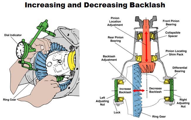
13 What precision measuring tool can check axial runout, backlash, & radial runout?
 Bearing D.")
14 Usually, noise that only occurs with the clutch pedal depressed is: A. Input Shaft Bearing B. Pilot Bearing C. Throw Out (Release) Bearing D. Universal Joint
 Bearing D.")
15 Typically, squeak 3x faster than vehicle speed is: A. Input Shaft Bearing B. Pilot Bearing C. Throw Out (Release) Bearing D. Universal Joint
16 Typically noise that occurs in neutral with the clutch engaged is: A. Input Shaft Bearing B. Pilot Bearing C. Throw Out (Release) Bearing D. Universal Joint

17 Hard to shift into a gear complaint could be caused by: A. Transmission Internal Problem B. Pilot Bearing Binding C. Shift or Clutch Linkage Problem D. All of the Above
 Side Gears D.")
18 What is the clutch friction disc splined to? A. Input Shaft B. Output Shaft C. Differential (Final Drive) Side Gears D. Wheel Bearing Hub
 Side Gears D.")
19 What is the RWD drive shaft slip yoke splined to? A. Input Shaft B. Output Shaft C. Differential (Final Drive) Side Gears D. Wheel Bearing Hub
 Side Gears D.")
20 What is the FWD half shaft inboard joint splined to? A. Input Shaft B. Output Shaft C. Differential (Final Drive) Side Gears D. Wheel Bearing Hub
 Side Gears D.")
21 What is the FWD half shaft outboard joint splined to? A. Input Shaft B. Output Shaft C. Differential (Final Drive) Side Gears D. Wheel Bearing Hub
22 What is the RWD axle shaft splined to? A. Input Shaft B. Output Shaft C. Differential (Final Drive) Side Gears D. Wheel Bearing Hub

23 Name the Hydraulic Clutch Parts A. B. D. E. C.

24 Know the hydraulic clutch parts & which way they move.

25 Name the Basic Clutch Parts A. E. F. D. C. B.

 Bearing D.")
26 Bearing mounted in either the output end of the crankshaft or the center of the flywheel A. Input Shaft Bearing B. Pilot Bearing C. Throw Out (Release) Bearing D. Center Support Bearing


")
27 Supports the drive shaft slip yoke A. Extension Housing Bushing B. Pilot Bearing C. Throw Out (Release) Bearing D. Center Support Bearing

28 Also known as the differential drive pinion A. Differential Pinion B. Spider Gear C. Input Pinion Gear D. Axle Side Gear


")
29 Support between the halves of a 2 piece RWD drive shaft A. Extension Housing Bushing B. Pilot Bearing C. Throw Out (Release) Bearing D. Center Support Bearing


30 Output component of a hydraulic clutch system A. Master Cylinder B. Slave Cylinder C. Clutch Cable D. Shift Linkage
 A. Ring Gear B. Spider Gear C. Input Pinion Gear D.")
31 Also known as the differential crown gear, it s the output component of a hypoid gearset (hypoid is most common intersects below center) A. Ring Gear B. Spider Gear C. Input Pinion Gear D. Axle Side Gear

32 Know the parts of an open differential.

33 Know the difference between an open & a limited slip differnetial.
 A. Differential Pinions B. Spider Gears C. Axle Side Gears D.")
34 The main wear components in an open differential when one wheel travels faster than the other (cornering, space saver spare, spinning) A. Differential Pinions B. Spider Gears C. Axle Side Gears D. Both A & B


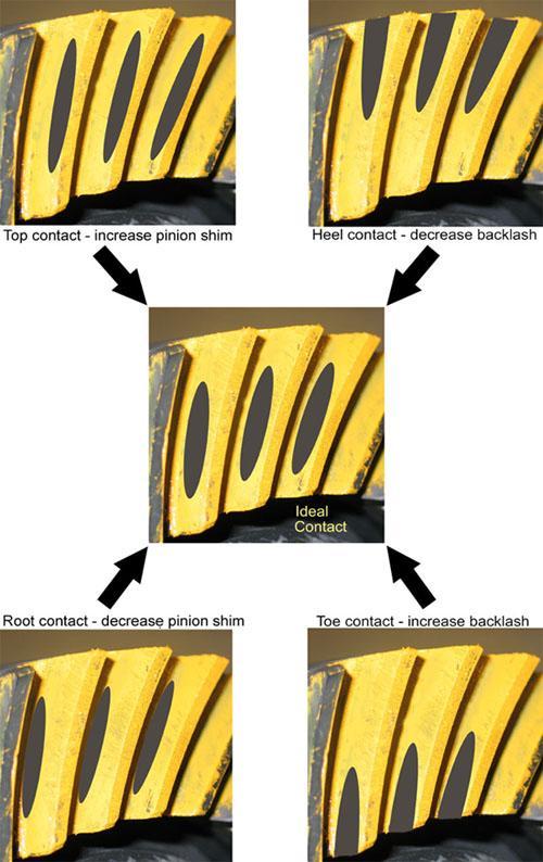
35 Term for tightness of the bearings in a 2 tapered roller bearing set A. Gearset Backlash B. Axial Play C. Bearing Preload D. Contact Pattern


36 Wave springs between the clutch friction disc facings A. Torsional Dampening Springs B. Cushioning Springs C. Diaphragm Spring D. Clutch Pedal Spring
37 The term meaning play or looseness in a gear set A. Gearset Backlash B. Axial Play C. Bearing Preload D. Contact Pattern
38
39


40 Coil springs or rubber bumpers on a clutch friction disc used to absorb engine impulses A. Torsional Dampening Springs B. Cushioning Springs C. Diaphragm Spring D. Clutch Pedal Spring

41 Term for lateral movement in a gear set or a bearing set A. Gearset Backlash B. Axial Play C. Bearing Preload D. Radial Runout


42 Before aligning a clutch disc, fill the pilot bearing with: A. RTV Sealant B. High Temperature Grease C. Engine Oil D. Either ATF or SAE 80w90

43 Know the parts of typical FWD, RWD, and 4WD drive trains.

44 Know the parts of typical FWD, RWD, and 4WD drive trains.
Manual Transmission/Driveline. Final Review
 Manual Transmission/Driveline Final Review 1. The Pressure Plate is a spring-loaded device that presses the clutch disc against the flywheel. 2. The clutch Release Mechanism allows the driver to disengage
Axles & Differentials
 ATASA 5 th Study Guide Chapter 39 Pages 1138 1172 60 Points Please Read The Summary Before We Begin Keeping in mind the Career Cluster of Transportation, Distribution & Logistics Ask yourself: What TDL
UNIT III TRANSMISSION SYSTEMS CONTENTS: Clutch-types and construction Gear boxes- manual and automatic Gear shift mechanisms Over drive Transfer box
 UNIT III TRANSMISSION SYSTEMS CONTENTS: Clutch-types and construction Gear boxes- manual and automatic Gear shift mechanisms Over drive Transfer box Fluid flywheel Torque converter Propeller shaft Slip
ASE Practice Test A3 Manual Drive Train
 Clutch Diagnosis and Repair ASE Practice Test A3 Manual Drive Train 1) Which of the following are the three critical clutch pedal measurements? a. Pedal height, apply pressure, and free play b. Pedal free
Clutches for Automobiles and Light Trucks
 Clutches for Automobiles and Light Trucks What does the Clutch do? Connects the engine torque to transmission when ENGAGED Unhooks engine from transmission when DISENGAGED Where is the driver s foot when
AUT 231 (A3) MANUAL TRANSMISSION/TRANSAXLE AND DRIVETRAIN
 MANUAL TRANSMISSION/TRANSAXLE AND DRIVETRAIN") AUT 231 (A3) MANUAL TRANSMISSION/TRANSAXLE AND DRIVETRAIN COURSE DESCRIPTION: Prerequisites: TRN 120 Corequisites: None This course covers the operation, diagnosis, and repair of manual transmissions/transaxles,
AUT 231 (A3) MANUAL TRANSMISSION/TRANSAXLE AND DRIVETRAIN COURSE DESCRIPTION: Prerequisites: TRN 120 Corequisites: None This course covers the operation, diagnosis, and repair of manual transmissions/transaxles,
ATASA 5 th Study Guide Chapter 36 Pages Clutches 74 Points. Clutches. Be Certain to Read the Summary
 ATASA 5 th Study Guide Chapter 36 Pages 1071 1091 74 Points Be Certain to Read the Summary 1. The provides a mechanical coupling between the engine s & the transmission s shaft. The clutch allows the engine
DIM Drive Train Systems
 2014 NATEF JOB TASKS COMPLETION REQUIREMENT: P1-95% P2-70% P3-25% Student Name: DETAILED COURSE CONTENT II. DRIVE TRAIN A. CLUTCH -- The student will be able to: P1 P2 P3 Level Date 1. Identify causes
Purposes of a Drive Axle Assembly
 Differentials Purposes of a Drive Axle Assembly To transmit power from the drive shaft to the wheels To turn the power flow 90 degrees on RWD cars To allow the wheels to turn at different speeds while
Clutch Clut Fundament Fundamen als t Chapter 69
 Clutch Fundamentals Chapter 69 Objectives Describe the basic clutch parts Explain the operation of the clutch Compare differences in clutch hdesign Describe the different methods of releasing the clutch
Clutch System Troubleshooting Guide-Service Tips
 DESCRIPTION AND OPERATION Clutch System The purpose of the clutch is to connect and disconnect a manually operated transmission and the remainder of the powertrain system from the engine. This permits
MANUAL TRANSMISSION SERVICE
 MANUAL TRANSMISSION SERVICE Introduction Internal combustion engines develop very little torque or power at low rpm. This is especially obvious when you try to start out in direct drive, 4th gear in a
FRONT AXLE AND SUSPENSION FA 1
 FRONT AXLE AND SUSPENSION FA1 FRONT AXLE AND SUSPENSION FA2 FRONT AXLE AND SUSPENSION Troubleshooting TROUBLESHOOTING Problem Possible cause Remedy Page Wanders/pulls Tires worn or improperly inflated
REAR AXLE AND SUSPENSION RA 1
 REAR AXLE AND SUSPENSION RA1 RA2 REAR AXLE AND SUSPENSION Troubleshooting TROUBLESHOOTING Problem Possible cause Remedy Page Wanders/pulls Tires worn or improperly inflated Replace tires or inflate to
Clutch cover Type Diaphragm spring strap. Clutch pedal Type Suspended type. Maximum operating travel
 000000 043 1. SPECIFICATION Operating type Description Hydraulic type Specification Clutch cover Type Diaphragm spring strap Adjusting type Clutch pedal Type Suspended type Max. operating travel Pedal
SUSPENSION AND AXLE Specifications (Front/2WD)
") A20 SUSPENSION AND AXLE Specifications (/2WD) Cold tire inflation pressure Pressure kpa (kgf/cm2, psi) Chassis ground clearance RN80L TRMDEA RN80L TRMDEK Clearance mm (in.) RN80L TRSDEA RN80L TRSDEK RN80L
A20 SUSPENSION AND AXLE Specifications (/2WD) Cold tire inflation pressure Pressure kpa (kgf/cm2, psi) Chassis ground clearance RN80L TRMDEA RN80L TRMDEK Clearance mm (in.) RN80L TRSDEA RN80L TRSDEK RN80L
This file is available for free download at
 This file is available for free download at http://www.iluvmyrx7.com This file is fully text-searchable select Edit and Find and type in what you re looking for. This file is intended more for online viewing
Drive pinion and ring gear, adjusting
 Page 1 of 8 39-33 Drive pinion and ring gear, adjusting Note: Careful adjustment of the drive pinion and ring gear is important for the service life and smooth running of the final drive. For this reason,
A 1 SERVICE SPECIFICATIONS
 A1 A2 Clutch CLUTCH Specifications Pedal height (from asphalt sheet) Release point (from pedal stroke end position) Push rod play at pedal top Pedal freeplay Disc rivet head depth Disc runout Diaphragm
Symptom Suspect Area See page 5. Engine mounting (Loosen) 6. Clutch disc assy (Runout is excessive) 7. Clutch disc assy (Oily)
 6. Clutch disc assy (Runout is excessive) 7. Clutch disc assy (Oily)") CLUTCH CLUTCH SYSTEM (MTM) PROBLEM SYMPTOMS TABLE HINT: CLUTCH SYSTEM (MTM) Use the table below to help you find the cause of the problem. The numbers indicate the priority of the likely cause of the problem.
CLUTCH CLUTCH SYSTEM (MTM) PROBLEM SYMPTOMS TABLE HINT: CLUTCH SYSTEM (MTM) Use the table below to help you find the cause of the problem. The numbers indicate the priority of the likely cause of the problem.
Front Wheel Drive Notes
 Front Wheel Drive Notes Drive Axle Components Outer CV-joint Allows wheels to steer while axle is rotating Inner CV-joint Allows for suspension changes while axle is rotating Axle shaft Transmits power
 www.clubsuprafrance.com CLUTCH 1996 Toyota Supra 1995-96 Clutch Supra DESCRIPTION The single, dry-type disc clutch uses a hydraulicallyoperated master cylinder with a clutch release cylinder mounted on
SUSPENSION AND AXLE SA 1 SUSPENSION AND AXLE
 SA1 SA2 Troubleshooting TROUBLESHOOTING Problem Possible cause Remedy Front Page Rear Wanders/pulls Tires worn or improperly inflated Wheel alignment incorrect Hub bearing worn Front or rear suspension
Size 00 Size 0-5 Size 6-8. Technical Data. Setscrew 1TF 2TF 3TF 3) 2) R Pilot bore max.
 2) R Pilot bore max.") Standard for a torque range up to 6800 Nm Standard zinc-coated and yellow passivated ting possible while in place Asbestos-free and rust-resistant friction linings Securing of the setting nut by locking
Standard for a torque range up to 6800 Nm Standard zinc-coated and yellow passivated ting possible while in place Asbestos-free and rust-resistant friction linings Securing of the setting nut by locking
Troubleshooting. Pull Type Clutches - Poor Release
 Troubleshooting Pull Type Clutches - Poor Release Complaint Possible Causes Corrective Action Poor Release Intermediate plate sticking on drive lugs due to cocked drive pins (AS and EP 1402 only) (see
Introduction to Manual Transmissions & Transaxles
 Section 1 Introduction to Manual Transmissions & Transaxles Learning Objectives: 1. Identify the purpose and operation of transmissions. 2. Describe torque and torque multiplication. 3. Determine gear
Service Manual. LL30002 Rev. 7/03. HEAVY DUTY PUSH/PULL TYPE CLUTCHES
 Service Manual LL30002 Rev. 7/03 HEAVY DUTY PUSH/PULL TYPE CLUTCHES www.haldex.com Table of Contents Section One - Push Type Clutches Clutch Assembly Cutaway Detail............................1 Clutch
CLUTCH 6-1 CLUTCH TABLE OF CONTENTS
 PL CLUTCH 6-1 CLUTCH TABLE OF CONTENTS page DESCRIPTION AND OPERATION MODULAR CLUTCH ASSEMBLY....1 CLUTCH CABLE...1 CLUTCH INTERLOCK/UPSTOP SWITCH....1 DIAGNOSIS AND TESTING CLUTCH SYSTEM DIAGNOSIS...2
DRIVE AXLE Nissan 240SX DESCRIPTION & OPERATION AXLE RATIO & IDENTIFICATION AXLE SHAFT & BEARING R & I DRIVE SHAFT R & I
 DRIVE AXLE 1990 Nissan 240SX 1990 DRIVE AXLES Rear Axle - R200 240SX, 300ZX DESCRIPTION & OPERATION The axle assembly is a hypoid type gear with integral carrier housing. The pinion bearing preload adjustment
1. General GENERAL CL-2
 SYSTEM GENERAL 1. General The clutch is of a dry, single plate type with a diaphragm spring. The clutch is a push type clutch. When the pedal is depressed, the release bearing will press the center of
SACHS Clutches The Intelligent Choice for the Long Haul
 SACHS Clutches The Intelligent Choice for the Long Haul Twin XTend Clutch Installation Objectives: Identification Operation Tools Installation Troubleshooting Identification 15.5 Self Adjusting Clutch
3. Rear Axle REAR AXLE DRIVESHAFT SYSTEM A: GENERAL DS-9
 W1860BE.book Page 9 Tuesday, January 28, 2003 11:01 PM 3. Rear Axle A: GENERAL 1. EXCEPT DOHC TURBO MODELS The inboard end of each axle shaft is connected to the transmission via a double offset joint
CLUTCH Nissan 240SX DESCRIPTION PEDAL HEIGHT & FREE PLAY ADJUST CLUTCH ASSEMBLY R & I Clutch. Pathfinder, Pickup, 240SX, 300ZX
 CLUTCH 1990 Nissan 240SX 1990 Clutch Pathfinder, Pickup, 240SX, 300ZX DESCRIPTION Clutch is of dry, single disc type, with a diaphragm spring type pressure plate. Clutch release bearing is prelubricated.
Tech Note Truck 14 & 15.5 Twin Plate Cast Iron Type Installation Guidelines
 1. (14 & 15.5 ) Check condition of the flywheel. Grind to resurface or replace flywheel. Surface MUST BE machined or premature clutch failure can occur. Flywheel depth must be 2.938 (74.62mm) for 14 (350mm)
MAHARASHTRA STATE BOARD OF TECHNICAL EDUCATION (Autonomous) (ISO/IEC Certified)
 (ISO/IEC Certified)") (ISO/IEC - 700-005 Certified) Subject Code: 7307 Model Answer Page No: /9 Important Instructions to examiners: ) The answers should be examined by key words and not as word-to-word as given in the model
(ISO/IEC - 700-005 Certified) Subject Code: 7307 Model Answer Page No: /9 Important Instructions to examiners: ) The answers should be examined by key words and not as word-to-word as given in the model
DRIVE AXLE Volvo 960 DESCRIPTION & OPERATION AXLE IDENTIFICATION DRIVE AXLES Volvo Differentials & Axle Shafts
 DRIVE AXLE 1994 Volvo 960 1994 DRIVE AXLES Volvo Differentials & Axle Shafts 960 DESCRIPTION & OPERATION All 960 station wagon models use type 1041 rear axle assembly. All 960 4-door models use type 1045
Failure Diagnosis. The LuK guide to troubleshooting clutch system failures and malfunctions on agricultural vehicles
 Failure Diagnosis The LuK guide to troubleshooting clutch system failures and malfunctions on agricultural vehicles Contents Page Failure diagnosis / causes of failures Clutch fault diagnosis What is clutch
TSM54/52 MANUAL TRANSMISSION
 3B-1 SECTION 00 3B TSM54/52 MANUAL TRANSMISSION Table of Contents GENERAL INFORMATION... 3B-3 Overview... 3B-3 Specifications... 3B-4 System components... 3B-5 Shifting mechanism... 3B-17 Diagnostic information
1999 Toyota RAV DRIVE AXLES AWD & FWD Axle Shafts - RAV4 & RWD Axle Shafts - MR2. AWD & FWD Axle Shafts - RAV4 & RWD Axle Shafts - MR2
 1999-2000 DRIVE AXLES AWD & FWD Axle Shafts - RAV4 & RWD Axle Shafts - MR2 DESCRIPTION & OPERATION On RAV4 models, axle shafts transfer power from transaxle to front wheels (FWD), or front and rear wheels
DIAGNOSIS AND TESTING Procedure revision date: 05/18/2000. SYMPTOM CHART TRANSMISSION, MANUAL Condition Possible Source Action
 SYMPTOM CHART TRANSMISSION,... SYMPTOM CHART TRANSMISSION, MANUAL (TRANSMISSION, MANUAL, M5OD) Section 07 03: Transmission, Manual, M5OD 1996 Aerostar/Ranger/Explorer Workshop Manual DIAGNOSIS AND TESTING
Diagnostic Procedures
 Section 6 Diagnostic Procedures Learning Objectives: 1. Describe manual transmission, transaxle and transfer case component inspection and diagnostic procedures 2. Identify clutch component inspection
2003 Dodge Pickup R DRIVE AXLES' 'Axle Shafts - Front - Ram Pickup WD DRIVE AXLES
 2002-04 DRIVE AXLES Axle Shafts - Front - Ram Pickup 1500 4WD DESCRIPTION Vehicles equipped with 4WD and C205F front axle assembly use equal length axle shaft system to deliver power from front differential
1994 Mazda MX-5 Miata. CLUTCH 1994 Clutch
 CLUTCH 1994 Clutch DESCRIPTION Miata uses a hydraulically operated clutch. HYDRAULIC SYSTEM BLEEDING 1. Remove bleeder screw cap, located at clutch release cylinder. Install vinyl hose onto bleeder screw.
70001 and Clutch Rebuild Instructions
 70001 and 70010 Clutch Rebuild Instructions Brinn, Incorporated 1615 Tech Drive Bay City, MI 48706 Telephone 989.686.8920 Fax 989.686.6520 www.brinninc.com Notice Use these instructions if you only want
Self-Adjust Clutch Installation Guide
 Self-Adjust Clutch Installation Guide 0 STOP! READ CAREFULLY BEFORE INSTALLING CLUTCH This clutch must be installed by a qualified installer. Improper installation or failure to replace or resurface the
CLUTCH COMPONENT LOCATION INDEX
 2005 TRANSMISSION Clutch - MX-5 Miata CLUTCH COMPONENT LOCATION INDEX Fig. 1: Identifying Clutch Components GENERAL PROCEDURES (CLUTCH) PRECAUTION Clutch pipe If any clutch pipe has been disconnected anytime
CLUTCH. Section IV DATA AND SPECIFICATIONS CHRYSLER SERVICE MANUAL. Page. Clutch Pedal Adjustment 74. Clutch Disassembly 77. Clutch Assembly 78
 CLUTCH 73 Section IV CLUTCH Page Clutch Pedal Adjustment 74 Clutch Disassembly 77 Clutch Assembly 78 Service Diagnosis 81 DATA AND SPECIFICATIONS MODEL TYPE 1376 (Borg-Beck) Single Plate, Dry Disc FACINGS
ENGINE CLUTCH CONTENTS OF THIS SECTION
 ENGINE CLUTCH 6C-l ENGINE CLUTCH CONTENTS OF THIS SECTION SUBJECT General Description Periodic Service Adjustments on Car Removal of Clutch Inspection of Clutch Parts Installation of Clutch Specifications
DF 47 DIFFERENTIAL REAR DIFFERENTIAL CARRIER ASSEMBLY REMOVAL
 47 REMOVAL 1. DISCONNECT CABLE FROM NEGATIVE BATTERY TERMINAL 2. REMOVE REAR WHEEL 3. DRAIN BRAKE FLUID Immediately wash off any brake fluid that comes into contact with any painted surfaces. 4. DRAIN
Knowledge of heavy vehicle transmission and driveline units and components
 Unit 262 Knowledge of heavy vehicle transmission and driveline units and components UAN: F/601/4963 Level: Level 2 Credit value: 6 GLH: 45 Relationship to NOS: This unit is linked to HV12 Remove and Replace
General repair instructions
 Page 1 of 10 00-10 The maximum possible care, cleanliness and proper tools are essential to ensure satisfactory and successful transmission repairs. The usual basic safety precautions also apply when carrying
FRONT AXLE & FRONT SUSPENSION SECTIONFA CONTENTS
 FRONT AXLE & FRONT SUSPENSION SECTIONFA CONTENTS PRECAUTIONS...2 PREPARATION...3 FRONT AXLE AND FRONT SUSPENSION...4 CHECK AND ADJUSTMENT...5 Front Axle and Front Suspension Parts...5 Front Wheel Bearing...6
CLUTCH 6-1 CLUTCH CONTENTS
 TJ CLUTCH 6-1 CLUTCH CONTENTS page GENERAL INFORMATION CLUTCH COMPONENTS... 1 INSTALLATION METHODS AND PARTS USAGE... 1 DESCRIPTION AND OPERATION CLUTCH OPERATION... 1 DIAGNOSIS AND TESTING DIAGNOSTIC
2007 Hummer H Driveline/Axle Rear Drive Axle - H3. Axle Preload and Backlash Specifications Specification Application
 2007 Driveline/Axle Rear Drive Axle - H3 SPECIFICATIONS AXLE PRELOAD AND BACKLASH SPECIFICATIONS Axle Preload and Backlash Specifications Specification Application Metric English Backlash 0.08-0.25 mm
CLUTCH PREPARATION Union Nut Wrench 10 mm Clutch Guide Tool Input Shaft Front Bearing Puller
 CLUTCH CL1 CL2 PREPARATION SST (SPECIAL SERVICE TOOLS) CLUTCH PREPARATION 0902300100 Union Nut Wrench 10 mm Clutch line 0930100110 Clutch Guide Tool 0930335011 Input Shaft Front Bearing Puller 0930430012
DRIVE AXLE - INTEGRAL HOUSING
 DRIVE AXLE - INTEGRAL HOUSING 1993 Toyota Celica 1993 DRIVE AXLES Toyota Differentials & Axle Shafts - Integral Housing Toyota; Celica All-Trac DESCRIPTION Drive axle assembly is a hypoid type with integral
AUTOMATIC TRANSMISSIONS Mitsubishi F3A20 Series TRANSMISSION APPLICATION TABLE
 Article Text ARTICLE BEGINNING AUTOMATIC TRANSMISSIONS Mitsubishi F3A20 Series APPLICATION TRANSMISSION APPLICATION TABLE Vehicle Application Transmission Model Colt 3-Speed (1990-94)... F3A21 Colt Vista
Magnesium Option, Late Model Front Seal, Viton, P/N 67256V Rear Seal, Viton, P/N 67257V Shifter Installed Heat Treated Yoke, P/N
 DESCRIPTION OPTION Magnesium Option, Late Model 80100L Front Seal, Viton, P/N 67256V 80109 Rear Seal, Viton, P/N 67257V 80110L Shifter Installed 80112L Heat Treated Yoke, P/N 62946-6 80119-6 Heat Treated
Clutch Installation Guide
 Clutch Installation Guide 0 STOP! READ CAREFULLY BEFORE INSTALLING CLUTCH This clutch must be installed by a qualified installer. Improper installation or failure to replace or resurface the flywheel,
TION AND OPERATION Procedure revision date: 01/22/1999
 TION AND OPERATION Procedure revision date: 01/22/1999 Main Components and Functions AX4S Main Components http://www.fordtechservice.dealerconnection.com/pubs/content/~wsww/~mus~len/20/sww71006.htm (1
REAR AXLE Click on the applicable bookmark to selected the required model year
 REAR AXLE 27-2 REAR AXLE General Information GENERAL INFORMATION 27100010118 The rear axle is a banjo-type semi-floating type. The axle shaft bearings are: *Single taper bearings for vehicles without
REAR AXLE GROUP CONTENTS GENERAL DESCRIPTION DRIVE SHAFT ASSEMBLY REAR AXLE DIAGNOSIS
 27-1 GROUP 27 CONTENTS GENERAL DESCRIPTION 27-2 DIAGNOSIS 27-2 INTRODUCTION 27-2 TROUBLESHOOTING STRATEGY 27-2 SYMPTOM CHART 27-3 SYMPTOM PROCEDURES 27-3 SPECIAL TOOLS 27-8 ON-VEHICLE SERVICE 27-12 TOTAL
DF 78. HINT: Face the rough side of the thrust washer marked by # to the differential case. INSPECTION
 78 DIFFERENTIAL REAR DIFFERENTIAL CARRIER ASSEMBLY (w/ Differential Lock) Face the rough side of the thrust washer marked by # to the differential case. INSPECTION 1. DIFFERENTIAL SIDE GEAR (w/ LSD Differential)
CLUTCH 6-1 CLUTCH CONTENTS
 Z CLUTCH 6-1 CLUTCH CONTENTS page page CLUTCH DIAGNOSIS... 2 CLUTCH SERVICE... 9 CLUTCH COMPONENTS MECHANICAL COMPONENTS The clutch mechanism in Grand Cherokee models with manual transmission consists
PROPELLER SHAFT & DIFFERENTIAL CARRIER SECTIONPD CONTENTS
 PROPELLER SHAFT & DIFFERENTIAL CARRIER SECTIONPD CONTENTS PREPARATION...2 PROPELLER SHAFT...5 On-Vehicle Service...6 Removal and Installation...7 Inspection...7 Disassembly...7 Assembly...8 ON-VEHICLE
SISU DP-330 DRIVE GEAR. Maintenance Manual
 SISU DP-330 DRIVE GEAR Maintenance Manual Sisu Axles, Inc. Autotehtaantie 1 PO Box 189 Fin-13101 Hameenlinna Finland Phone +358 204 55 2999 Fax +358 204 55 2900 DP330DG.PDF (3/2007) TABLE OF CONTENTS
Clutch Diagnosis - Causes of Failure
 Clutch Diagnosis - Causes of Failure Guide Tube wear, Spline wear, Mainshaft Bearing wear Worn Flywheel Bearing, ridged or heat damaged Flywheel surface Worn/siezed Release Arm pivots, friction lining
Service Manual. 1320, 1520 and 1720
 Service Manual Service Manual 1320, 1520 and 1720 THIS IS A MANUAL PRODUCED BY JENSALES INC. WITHOUT THE AUTHORIZATION OF NEW HOLLAND OR IT S SUCCESSORS. NEW HOLLAND AND IT S SUCCESSORS ARE NOT RESPONSIBLE
AXLE SHAFTS - 2.2L Toyota Celica DESCRIPTION TROUBLE SHOOTING REMOVAL, DISASSEMBLY, REASSEMBLY & INSTALLATION AXLE SHAFTS
 AXLE SHAFTS - 2.2L 1994 Toyota Celica 1994 DRIVE AXLES Toyota FWD Axle Shafts Celica 2.2L 4 Cyl DESCRIPTION Axle shafts transfer power from transaxle to the front wheels. Axle shaft consists of axle shaft
1. General Description
 1. General Description A: SPECIFICATION 1. MANUAL TRANSMISSION AND FRONT DIFFERENTIAL Type Transmission gear ratio Front reduction gear Rear reduction gear Front differential Center differential Final
Rear Drive Axle and Differential
 Page 1 of 13 Rear Drive Axle and Differential GENERAL Item Part Number Description A - Electronic rear differential B - Open rear differential 1 - Rear driveshaft 2 - Electronic rear differential 3 - RH
DISASSEMBLY AND ASSEMBLY (Continued)
") 205-03-23 Front Drive Axle/Differential Ford 8.8-Inch Ring Gear 205-03-23 49. Measure the ring gear backlash at four places to obtain a consistent reading. 1 Mount the special tools on the indicator base.
205-03-23 Front Drive Axle/Differential Ford 8.8-Inch Ring Gear 205-03-23 49. Measure the ring gear backlash at four places to obtain a consistent reading. 1 Mount the special tools on the indicator base.
Halfshaft. Special Tool(s) Differential Plug (T89P-4850-B) Differential Seal Protector Halfshaft Removal Tool
 Differential Plug (T89P-4850-B) Differential Seal Protector Halfshaft Removal Tool") Halfshaft Special Tool(s) Differential Plug 205-294 (T89P-4850-B) Differential Seal Protector 205-461 Halfshaft Removal Tool 205-475 Hub Remover/Replacer 204-069 (T81P-1104-C) Metric Hub Remover Adapter
Halfshaft Special Tool(s) Differential Plug 205-294 (T89P-4850-B) Differential Seal Protector 205-461 Halfshaft Removal Tool 205-475 Hub Remover/Replacer 204-069 (T81P-1104-C) Metric Hub Remover Adapter
Take off case cover.
 33 14 520 Replacing complete locking differential (Type M) - final drive removed - Removing and installing final drive, included in Repair Manual MF, model-dependent, from '85, refer to 33 10 010. Drain
6-speed manual gearbox 0A5
 Service Training Self-study programme 320 6-speed manual gearbox 0A5 Design and function S320_002 In addition to meeting increasing technical demands, modern cars also have to represent effective space
DESCRIPTION AND OPERATION > CLUTCH CONTROLS
 Page 1 of 17 2004 Ford Mustang 3.9L Eng Base Service Manual: CLUTCH CONTROLS Print Date: DESCRIPTION AND OPERATION > CLUTCH CONTROLS Fig 1: Identifying Clutch Controls Components Page 2 of 17 The clutch
1994 Mitsubishi Eclipse GS
 APPLICATIONS CHRYSLER MOTORS MANUAL TRANS OVERHAUL - MITSUBISHI W5M & W6M SERIES MANUAL TRANSMISSIONS Mitsubishi W5M31, TRANSMISSION APPLICATIONS (CHRYSLER MOTORS) Vehicle Application Transmission Model
TO INDEX DIFFERENTIAL FRONT DIFFERENTIAL CARRIER OIL SEAL (4WD) FRONT DIFFERENTIAL CARRIER ASSEMBLY (4WD) REAR DIFFERENTIAL CARRIER OIL SEAL
 FRONT DIFFERENTIAL CARRIER ASSEMBLY (4WD) REAR DIFFERENTIAL CARRIER OIL SEAL") TO INDEX DRIVE LINE / AXLE DIFFERENTIAL DIFFERENTIAL SYSTEM PRECAUTIONS.............................................. OPERATION CHECK......................................... PROBLEM SYMPTOMS TABLE.................................
TO INDEX DRIVE LINE / AXLE DIFFERENTIAL DIFFERENTIAL SYSTEM PRECAUTIONS.............................................. OPERATION CHECK......................................... PROBLEM SYMPTOMS TABLE.................................
Module 6: Air Foundation Brakes
 Air Brakes Terms and Definitions Basic Components That Make Up Air Foundation Brakes Types of Air Foundation Brakes Parts of a Cam Foundation Brake Parts of a Wedge Foundation Brake Parts of a Disc Foundation
5/6 Speed Conversions for Subaru SVX
 5/6 Speed Conversions for Subaru SVX using custom parts available from TomsSVX 4/19/06 Parts list for 5/6mt swap 5/6mt assembly 5/6mt shift linkage(be sure to get all the pieces) 5/6mt starter(both are
Take off case cover.
 33 14 520 Removing complete locking differential. (Type K) - final drive removed - Removing and installing final drive, refer to 33 10 010 Drain off fluid. Secure final drive to special tool 33 1 010 (retaining
2007 Hummer H Driveline/Axle Propeller Shaft - H3. Fastener Tightening Specifications Specification Application
 2007 Driveline/Axle Propeller Shaft - H3 SPECIFICATIONS FASTENER TIGHTENING SPECIFICATIONS Fastener Tightening Specifications Specification Application Metric English Bolt - Front Propeller Shaft CV Joint
REMOVAL AND INSTALLATION
 204-00-1 Suspension System 204-00-1 REMOVAL AND INSTALLATION Wheel Bearing, Hub, Knuckle, Upper Arm and Lower Arm Rear Special Tool(s) 3. Remove the parts in the order indicated in the following illustrations
1992 Clutch. Eclipse, Expo/Expo LRV, Galant, Mirage, Precis, 3000GT
 Article Text ARTICLE BEGINNING 1992 Clutch Eclipse, Expo/Expo LRV, Galant, Mirage, Precis, 3000GT DESCRIPTION All clutches are single disc type. Pressure plate assembly uses a diaphragm spring to engage
MTMANUAL TRANSMISSION GENERAL 1. SPECIFICATIONS. 1) General Specifications. 2) Tightening Torque MANUAL TRANSMISSION
 General Specifications. 2) Tightening Torque MANUAL TRANSMISSION") 03-3 MT GENERAL 1. SPECIFICATIONS 1) General Specifications 2) Tightening Torque 03-4 OVERVIEW AND OPERATION PROCESS 1. OVERVIEW 4WD Features 1. All gears use the helical type and high strength materials.
03-3 MT GENERAL 1. SPECIFICATIONS 1) General Specifications 2) Tightening Torque 03-4 OVERVIEW AND OPERATION PROCESS 1. OVERVIEW 4WD Features 1. All gears use the helical type and high strength materials.
DRIVE AXLE - 4WD MODELS WITH INTEGRAL HOUSING
 DRIVE AXLE - 4WD MODELS WITH INTEGRAL HOUSING 1988 Toyota Celica DRIVE AXLES Toyota Integral Housing Celica (Rear) DESCRIPTION housing. Drive axle assembly is hypoid type with integral carrier AXLE RATIO
REMOVAL & INSTALLATION
 REMOVAL & INSTALLATION AXLE SHAFTS & BEARINGS Removal CAUTION: Failure to turn off air suspension power before raising vehicle may result in unexpected inflation or deflation of air springs. DO NOT reconnect
1. General Description
 1. General Description A: SPECIFICATIONS 1. Type Transmission gear ratio Front reduction gear Rear reduction gear 2. TRANSMISSION GEAR OIL Recommended oil Final Transfer 5-forward speeds with synchromesh
LIFT TRUCK SERIES: G35S-2 G40S-2 G45S-2 G40SC-2 G45SC-2 G50SC-2. November 15, 2000 CODE 3150 LT3150-L0 SUBJECT: NEW DRIVE AXLE
 LIFT TRUCK SERIES: G35S-2 G40S-2 G45S-2 G40SC-2 G45SC-2 G50SC-2 November 15, 2000 CODE 3150 LT3150-L0 SUBJECT: NEW DRIVE AXLE A new drive axle has been introduced in the above model lift trucks. The purpose
HAKO cut-away models. 10: Clutches, Transmission, Automatic Transmission, Rear-wheel Drive, Front-wheel Drive, Steering, Chassis, Damping, Suspension
 10: Clutches, Transmission, Automatic Transmission, Rear-wheel Drive, Front-wheel Drive, Steering, Chassis, Damping, Suspension Order No. 1211 Clutch functional model A diaphragm spring clutch is mounted
PROPELLER SHAFT & DIFFERENTIAL CARRIER SECTIONPD CONTENTS IDX. PROPELLER SHAFT...3 Preparation...3 C200. REAR FINAL DRIVE...40 Preparation...
 PROPELLER SHAFT & DIFFERENTIAL CARRIER SECTIONPD GI MA EM LC EC CONTENTS FE PROPELLER SHAFT...3 Preparation...3 SPECIAL SERVICE TOOLS...3 Noise, Vibration and Harshness (NVH) Troubleshooting...4 NVH TROUBLESHOOTING
CLUTCH Toyota Celica DESCRIPTION ADJUSTMENTS CLUTCH PEDAL HEIGHT Clutch. Celica
 CLUTCH 1993 Toyota Celica 1993 Clutch Celica DESCRIPTION The single, dry disc type clutch uses a hydraulically operated master cylinder and a release cylinder mounted on clutch housing. Clutch release
SUSPENSION AND AXLE SA 1
 SUSPENSION AND AXLE SA1 SA2 TROUBLESHOOTING SUSPENSION AND AXLE TROUBLESHOOTING Use the table below to help you find the cause of the problem. The numbers indicate the priority of the likely cause of the
PROPELLER SHAFT / / PROPELLER SHAFT GENERAL OVERVIEW AND OPERATION PROCESS 1. SPECIFICATION...
 3310-01/3310-00/3310-06 GENERAL 1. SPECIFICATION... 3 OVERVIEW AND OPERATION PROCESS 1. OVERVIEW... 2. COMPONENT LOCATOR... 3310-01 FRONT... 3310-06 REAR... 3310-00 DISASSEMBLY AND REASSEMBLY PROPELLER
SECTION 5B MANUAL TRANSMISSION TABLE OF CONTENTS
 SECTION 5B MANUAL TRANSMISSION TABLE OF CONTENTS General Description and Operation... 5B-2 Shift Lever... 5B-2 Transmission Assembly... 5B-2 Specifications... 5B-3 Diagnostic Information and Procedures...
FRONT SUSPENSION AND AXLE
 J FRONT SUSPENSION AND AXLE 2-1 FRONT SUSPENSION AND AXLE CONTENTS page AXLE NOISE/VIBRATION DIAGNOSIS... 16 FRONT WHEEL ALIGNMENT... 5 GENERAL INFORMATION... 1 MODEL 30 AXLE AND TUBE AXLE (2WD).. 20 page
10/31/2018 R.M. 2005::Drive Shaft / Propeller Shaft: Front Drive Shaft: Overhaul (SCION xb) 2005 Scion XB MotoLogic
 2005 Scion XB MotoLogic") 2005 XB OVERHAUL Use the same procedures for the RH side and LH side. The procedures listed below are for the LH side. 1. DRAIN MANUAL TRANSAXLE OIL (M/T TRANSAXLE) Torque: 39 N m (398 kgf cm, 29 ft lbf)
2005 XB OVERHAUL Use the same procedures for the RH side and LH side. The procedures listed below are for the LH side. 1. DRAIN MANUAL TRANSAXLE OIL (M/T TRANSAXLE) Torque: 39 N m (398 kgf cm, 29 ft lbf)
G Class Transfer Case. 217 HO 06 Transfer Case (IC GC OP TF)
") G Class Transfer Case 217 HO 06 Transfer Case (IC GC OP TF) 1-30-03 2 These technical training materials are current as of the date noted on the materials, and may be revised or updated without notice.
G Class Transfer Case 217 HO 06 Transfer Case (IC GC OP TF) 1-30-03 2 These technical training materials are current as of the date noted on the materials, and may be revised or updated without notice.
Nissan Pathfinder (R50) Automatic to Manual Transmission Conversion Manual
 Automatic to Manual Transmission Conversion Manual") 1996 1999 Nissan Pathfinder (R50) Automatic to Manual Transmission Conversion Manual 1 1996 1999 Nissan Pathfinder (R50) Automatic to Manual Transmission Conversion Manual Conversion performed and Manual
1996 1999 Nissan Pathfinder (R50) Automatic to Manual Transmission Conversion Manual 1 1996 1999 Nissan Pathfinder (R50) Automatic to Manual Transmission Conversion Manual Conversion performed and Manual
Borg & Beck Clutch Information
 Borg & Beck Clutch Information After the clutch is bolted to the flywheel, under no circumstance should the release lever, or the release lever plate if equipped, be pulled away from the flywheel against