Service Manual. LL30002 Rev. 7/03. HEAVY DUTY PUSH/PULL TYPE CLUTCHES
|
|
|
- Morris Singleton
- 6 years ago
- Views:
Transcription


1 Service Manual LL30002 Rev. 7/03 HEAVY DUTY PUSH/PULL TYPE CLUTCHES
2 Table of Contents Section One - Push Type Clutches Clutch Assembly Cutaway Detail Clutch Construction and Operation Single Plate Clutch Installation and Flywheel Preparation Checking for Flywheel Misalignment Two-Plate Clutch Installation ,5 Dimension A Clutch Linkage Adjustment Clutch Linkage Requirements Dimension A /Flywheel Specifications Common Service Problems Section Two - Pull Type Clutches Clutch Assembly Cutaway Detail Clutch Construction and Operation Clutch Installation and Flywheel Preparation Single Plate Clutch Installation Two Plate with Adapter Ring Clutch Installation Two Plate with Strap Drive Clutch Installation Checking for Flywheel Misalignment Two Plate Pot/Recess Flywheel Clutch Installation Two Plate Flat Flywheel Clutch Installation Dimension A Transmission Installation Release Bearing Adjustment Clutch Linkage Adjustment Lubrication of Release Bearing Dimension A /Flywheel Specifications Common Service Problems Section Three - Adapter Kits 14-2 DPB and DLB - Push Type Adapter Kit Installation Pull Type Adapter Kit Installation /330-2 Plate Pot/Recess and Flat Flywheel Adapter Kit Installation
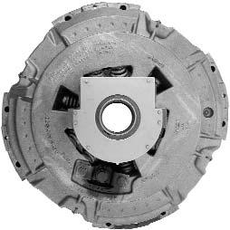
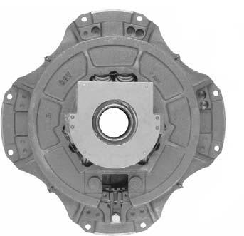
3 CLUTCH ASSEMBLY CUTAWAY DETAIL HEAVY DUTY PUSH TYPE CLUTCH Figure 1. Haldex 13 (330 mm) and 14 single plate clutch assembly on a flat flywheel. Figure 2. Haldex 14 single plate clutch assembly on a pot (recessed) flywheel. Figure 3. Haldex 13 (330 mm) and 14 two plate clutch assembly on a pot (recessed) flywheel. (Typical Drawings) Figure 4. Haldex 13 (330 mm) and 14 two plate clutch assembly on a flat flywheel with an adapter ring.
4 CLUTCH CONSTRUCTION The Haldex DPB, DLB, DO, DF and 330 type (direct pressure) clutches are precision built heavy duty units incorporating few parts. These clutch assemblies require no maintenance other than maintaining release bearing clearance which is accomplished by normal linkage adjustment. The DO clutch is similar to the DPB/DLB type clutch and differs in pressure plate finish, inside diameter and does not incorporate insulating washers as it operates in oil. The DO is manufactured in 13 and 14 single plate, 13 and 14 two plate sizes. The DLB clutches are also similar to the DPB type clutch and differ only in that the DLB are equipped with hardened steel drive lugs to afford the maximum amount of area to drive the pressure plate. The DLB also incorporates spring retainers on the inner row of pressure springs to prevent pressure spring flex at higher engine speeds. The DPB and DLB type are manufactured in 13 and 14 single and two plate sizes. The DF clutch is also similar to the DPB type clutch and differs only in that the DF is equipped with forged release levers. The DF type is manufactured in the 13 single plate size. CLUTCH OPERATION The operation of the Haldex Direct pressure clutch is as follows: The clutch flywheel ring (cover) is attached to the engine flywheel and drives the pressure plate by means of driving lugs in the flywheel ring (cover) and mating slots in the pressure plate. Depressing the clutch pedal forces the release bearing against the clutch release lever. As these levers travel inward (toward the engine) the pressure plate is retracted into the cover assembly compressing the pressure springs, which in turn allows the disc assembly to float freely between the pressure plate and the flywheel. Releasing the clutch pedal engages the clutch by allowing the release bearing and release levers to move away from the engine and the pressure springs to expand and exert force against the pressure plate, resulting in the disc assembly being gripped between friction surfaces of engine flywheel and pressure plate; thereby completely engaging the clutch. Figure 6. Recommended Counterbore SINGLE PLATE CLUTCH INSTALLATION AND FLYWHEEL PREPARATION Inspect Engine Flywheel 1. Check recessed type flywheels for correct depth. See Chart on Page Inspect the release bearing and carrier and flywheel pilot bearing. Pilot bearing should be a hand press fit in the flywheel recess and a slip fit on the transmission input shaft. The release yoke or fork should contact the release bearing carrier pads evenly to prevent a bind on the front bearing cap extension. 3. The friction face of the flywheel must be free from heat cracks, score marks, or taper and must be parallel to the crankshaft mounting flange. The presence of any of these conditions will have an adverse effect on clutch function and life. NOTE: Extremely Important - every time a flywheel is reinstalled or replaced it must be inspected for misalignment. (See Page 3 for instructions on checking flywheel misalignment). Installing Single Plate Clutch Assembly (See Figure 1 and Figure 2, Page 1) 1. It is a good idea to try the cover assembly on the flywheel without the disc assembly to insure proper fit where cover is piloted on the O.D. (Figure 2, Page1). NOTE: On DO (oil spray) clutch assemblies the driven discs must be soaked in oil prior to installation. Figure 5. Tightening Sequence 2. Install driven disc, making sure that it is properly positioned and insert an aligning shaft. Normally the long end of the driven disc hub extends toward the transmission, but in a few instances the long end may face toward the engine. A minimum of 5/32 must be maintained between the pilot bearing and the flywheel side disc hub. The minimum distance of 5/16 must be maintained between the flywheel friction face and the flywheel to crankshaft mounting bolt heads (Figure 7)
5 Figure 7. Checking For Flywheel Misalignment 3. Bolt the cover assembly to the flywheel using only SAE Grade 8 cap screws, tighten progressively in sequence (Figure 5) until the cover is drawn up tight using 35 to 45 lbs.-ft. of torque. Extreme care must be exercised to insure that the flywheel ring or cover is seated in the piloting rim on recessed type flywheels (Figure 2, Page 1). 4. Remove the cover assembly shipping block or hold down bolts, only after bolting to flywheel. 5. Cover assemblies mounted on flat flywheels (Figure 1, Page 1) are piloted to the flywheel by cap screws with a ground shank which fits the reamed holes in the cover. The machined shank extends through the cover into a recessed or counterbored hole in the flywheel (Figure 6). 6. If the flywheel has been re-machined to remove heat cracks or scores, the counterbored holes may require reaming to allow complete seating of the cover assembly. If the flywheel cannot be restored to original conditions, replace the flywheel. HEAVY DUTY PUSH TYPE CLUTCH ENGINE HOUSING INDICATOR (RUNOUT.008 MAX.) ENGINE FLYWHEEL ENGINE HOUSING INDICATOR (RUNOUT.008 MAX.) ENGINE FLYWHEEL For S.A.E. BELL NOS. 1,2 & 3 For S.A.E. BELL NOS. 1,2 & 3 1/2 CLUTCH DISC DIA. ENGINE HOUSING INDICATOR (RUNOUT.001 PER IN.) ENGINE HOUSING ENGINE FLYWHEEL INDICATOR (RUNOUT.005 MAX.) ENGINE FLYWHEEL The centerline or axis of the engine crankshaft, flywheel, clutch and transmission shall be common to these units with a permissible variation not to exceed.005 between any or all of these members
6 TWO PLATE CLUTCH INSTALLATION 1. The DPB, DLB, DO and DF two plate assemblies have an intermediate plate with driving lugs which fit into mating slots of the flywheel or adapter ring. NOTE: On DO (oil spray) clutch assemblies the driven discs must be soaked in oil prior to installation. 2. Before installing a two plate assembly, the intermediate plate should be set into the driving slots of the flywheel or adapter ring and clearances checked. A gap of.006 to.012 is recommended. Adapter Ring Applications NOTES: a. The adapter ring must be positioned so the ventilating slots are next to the flywheel. b. The intermediate plate is directional and must be installed as labeled. The slots for the intermediate plate must face transmission. c. On 13 - (330) flywheels that have less than 12 screw holes, use the adapter ring as a template to drill the other holes. A 3/8 drill should be used for spotting the holes. Drill with a 5/16 and tap the holes with a 3/8-16 UNC tap. Then install the ring in the same position as when spotting the holes to assure proper alignment. Figure Plate d. We suggest that a pair of standard 3/8-16 UNC cap screws 3 long be used as pilots. Cut the heads from these cap screws, saw a screwdriver slot in the end and install them in opposite holes in the flywheel. These pilots will support the adapter ring as the clutch is being installed. e. On remachined flywheels, insure the counterbores are still deep enough to allow secure tightening of the cover assembly and adapter ring to the flywheel (Figure 6, Page 2) Plate (Figure 9) Bolt Circle use Adapter Kit AK Bolt Circle use Adapter Kit Bolt Circle use Adapter Kit AK315 The 330mm cover assembly and adapter ring use a common mounting bolt (Figure 9). * For Chevrolet/GMC application with 409/427 engines having 7/16-14 mounting bolts use Adapter Kit AK 316 (Figure 8). The adapter ring is attached to the flywheel by (4) X2-140 cap screws in every third hole. (Applies only to 409 and 427 gas engines.) Figure Plate - 4 -
 C78-29 cap screws 2 1/8 long and can only be used on flywheels with 3/16 deep counterbores (Figure 6, Page 2).")

7 Figure Plate DLB, DPB 14-2 Plate DLB, DPB (Figure 10) The 14-2 plate DLB and DPB cover assemblies use a common mounting bolt. The AK206 Adapter Kit has (12) C78-29 cap screws 2 1/8 long and can only be used on flywheels with 3/16 deep counterbores (Figure 6, Page 2). NOTE: The 330mm clutch cover must be aligned to the intermediate plate. To do so place the stand directly over an intermediate plate drive lug (align 2 plate lug here). 6. Remove the cover assembly shipping blocks or hold down bolts and spline alignment tool. 7. To obtain complete disengagement of Type DPB, DLB, DO and DF clutch assemblies, the release levers must be actuated a specified distance from the engaged position. Assuming the release bearing clearance (distance between the clutch release levers and release bearing) to be 1/8 when the clutch is in the engaged position, the release bearing must move forward 1/8 to take up this clearance before it contacts the release levers. After the release bearing contacts the release lever 1/2 of additional travel is required to disengage the clutch assembly (Figure 13, Page 6). DIMENSION A 1. Dimension A is the distance from the top of the clutch flywheel ring cover to the ends of release levers (Figure 11). 2. Check chart on Page 7 for correct A Dimension. Satisfactory operation of the clutch depends greatly upon the accuracy of the lever setting, as this controls the parallel movement of the pressure plate. HEAVY DUTY PUSH TYPE CLUTCH The AK208 Adapter Kit has (12) C78-27 cap screws 2 long and is intended for flywheels with counterbores 1/8 deep (Figure 6, Page 2). 3. The two disc assemblies for a two plate clutch may or may not be identical or interchangeable. In most cases they will not be interchangeable and will be marked either flywheel side or pressure plate side. They must be positioned with the side of the disc as marked, next or adjacent to the respective part. A minimum of 5/32 must be maintained between the pilot bearing and the flywheel side disc hub. The minimum distance of 5/16 must be maintained between the flywheel friction face and the flywheel mounting bolt heads (Figure 7, Page 3). NOTE: If the disc assemblies are equipped with cera-metallic button facing it is suggested that the facing material on the two discs be lined up. 4. When installing two plate clutches, it is essential that a splined shaft or aligning shaft (Haldex TCT14 1 1/2-10, TCT15 1 3/4-10 or TCT ) be used to properly align the two disc assemblies. 5. With a spline alignment tool place the driven discs and intermediate plate on the flywheel. Attach the clutch cover assembly to the flywheel using the 12 cap screws provided in the adapter kit. Do not tighten any cap screws until all 12 have been installed and finger tight, torque to lbs.-ft. (See Figure 5, Page 2, for tightening sequence.) 3. A straight edge and scale can be used to check the A Dimension as shown in Figure New or genuine Haldex Heavy Duty exchange cover assemblies are pre-adjusted at the factory and the lever settings shall not be altered. If the A Dimension does not check out according to the chart on Page 7 within 1/8, recheck the complete installation. If after rechecking the installation, the A Dimension still does not check out, return the cover assembly for exchange. NOTE: If release levers are not in plane, it is an indication that the cover is not properly seated in the flywheel. Check A Dimension (Figure 11) and see chart on Page 7. Figure 11. Checking A Dimension - 5 -
.")
 and 1/2 that the release lever must move inward to complete clutch disengagement (Figure 13). 2.")
8 CLUTCH LINKAGE ADJUSTMENT Never wait for the clutch to slip before making a pedal adjustment. 1. Keep the clutch pedal in proper adjustment by frequent inspection of the Free Travel (the first easy movement of the clutch pedal). CLUTCH LINKAGE REQUIREMENTS The clutch pedal linkage is required to move the release bearing approximately 5/8. This 5/8 is made up of 1/8 clearance between the bearing and the release levers (free play) and 1/2 that the release lever must move inward to complete clutch disengagement (Figure 13). 2. Check clutch pedal with your hand to be positive that Free Travel is a result of actual release bearing clearance and not caused by worn linkage (Figure 12). 3. Proper clutch pedal Free Travel is approximately 1 1/2. The gradual reduction from this amount is a normal condition caused by wearing of the disc friction facings. Figure 13. Total Release Bearing Travel Must Be Approximately 5/8 Figure 12. Checking Clutch Pedal Free Travel 4. If inspection indicates clutch pedal Free Travel is less than 1/2, immediate adjustment of the clutch pedal linkage should be made to restore proper 1 1/2 Free Travel (Figure 12). This 1 1/2 pedal Free Travel normally results in 1/8 clearance between the clutch release levers and release bearing. 5. If excessive free play is present in the clutch pedal linkage due to worn parts, the worn parts must be replaced. Excessive wear of the release linkage may give a false impression of the actual amount of release bearing clearance. CAUTION: Excessive clutch pedal Free Travel may prevent complete clutch disengagement while insufficient clutch pedal Free Travel may cause slippage and short clutch life
9 DIMENSION A / FLYWHEEL SPECIFICATIONS ASM Old ASM NEW Dimension Flywheel Part Part A Depth Number Number + 1/ W W*** 29/ / / W*** 1 3/ /32 Flat *** 25/ / /32 Flat OBSOLETE 7/8 Flat / W W*** 15/ W*** 15/ W W*** 15/ /32 Flat / W W* 1 3/ / /32 Flat W 29/32 Flat / / / / /32 Flat W W*** 29/ /32 Flat /32 Flat W*** 29/ W*** 29/ /32 Flat ASM Old ASM NEW Dimension Flywheel Part Part A Depth Number Number + 1/ / /32 Flat /32 Flat / W 2 59/64 Flat OBSOLETE 1 3/16 Flat / / /16 Flat /32 Flat W** 19/ /32 Flat /8 Flat W W** 23/ /32 Flat /32 Flat /32 Flat /16 Flat /32 Flat # 9/ W W** 23/ /32 Flat /32 Flat /32 Flat /32 Flat W W 27/ /32 Flat /32 Flat /32 Flat /32 Flat HEAVY DUTY PUSH TYPE CLUTCH Intermediate Plate Thickness: * /-.003 ** /-.003 *** /-.003 # /-.003 Note: Tolerances for remanufactured clutches are the same as new clutches
10 COMMON SERVICE PROBLEMS Problem Remedy CHATTER 1. Loose, broken or worn engine mounts 1. Tighten or replace 2. Worn pedal linkage 2. Replace linkage 3. Loose or cracked clutch housing 3. Tighten or replace 4. Spring shackles and mountings loose, worn or broken 4. Tighten or replace 5. Misalignment 5. Realign 6. Oil or grease on facings 6. Install new facings or disc assembly 7. Warped or bent driven disc assembly 7. Install new disc assembly 8. Improper disc facing thickness 8. Install proper disc assembly 9. Worn pilot bearing 9. Replace 10. Wrong spring pressure in cover assembly 10. Replace with proper cover assembly 11. Improper A dimension (Type ML Only) 11. Adjust for A dimension according to ML Service Manual 12. Unequal quantity of shims under straps of ML clutch 12. Use same quantity of shims under each strap 13. Release levers not parallel 13. Recheck installation AGGRESSIVE 1. Release sleeve dry (Type ML Only) 1. Lubricate release sleeve 2. Worn or loose pedal linkage 2. Replace or tighten 3. Excessive backlash in power train 3. Adjust or replace worn parts 4. Warped driven disc 4. Install new disc assembly 5. Worn hub splines 5. Install new disc assembly 6. Worn or rusty splines on input shaft 6. Replace shaft or install Haldex Spline-Saver disc kit 7. Improper facing material 7. Install proper disc assembly 8. Loose cera-metallic button facing 8. Replace facing or install new disc assembly 9. Burned cera-metallic button facing 9. Replace facing or install new disc assembly INSUFFICIENT RELEASE 1. Loose, broken or worn motor mounts 1. Tighten or replace 2. Worn or loose pedal linkage 2. Tighten or replace 3. Excessive idle speed 3. Adjust to factory specification 4. Loose or worn facings 4. Replace facings or install new disc assembly 5. Improper facing thickness 5. Install proper disc assembly 6. Warped or bent driven disc assembly 6. Properly install recommended disc assembly 7. Lever setting wrong 7. Refer to your Haldex Service Manual 8. Worn hub splines 8. Replace with new disc assembly 9. Worn or rusty splines or input shaft 9. Replace shaft or install Haldex Spline-Saver disc kit 10. Worn pilot bearing 10. Replace 11. Worn or cocked drive pins 11. replace or align 12. Insufficient release bearing travel 12. Repair or replace linkage HARD PEDAL 1. Worn pedal linkage 1. Replace with new linkage 2. Worn cross shaft, cross shaft bushing or yoke 2. Replace with new cross shaft, cross shaft bushing or yoke 3. Binding in pedal linkage (rod or cable) 3. Lubricate, adjust or replace 4. Excessive spring pressure in cover assembly 4. Install proper cover assembly 5. Contact pad of release bearing carrier worn by shifter yoke 5. Replace carrier and shifter yoke. Also check for proper alignment to provide best linkage operating positions. SLIPPAGE 1. Oil or grease on facing 1. Replace facing or install new disc assembly and correct oil leak 2. Loose or worn facings 2. Replace facings or install new disc assembly 3. Flywheel burned, checked, cracked or dished 3. Replace or regrind flywheel to manufacturer s specifications 4. Insufficient plate pressure 4. Install new cover assembly 5. Improper A dimension (Type ML Only) 5. Adjust A dimension to proper height 6. Binding in pedal linkage 6. Lubricate and adjust 7. Improper facing material 7. Use correct facing or replace disc assembly 8. Incorrect flywheel depth 8. Replace or regrind flywheel to manufacturer s specifications 9. Incorrect disc thickness 9. Replace facing or install new disc assembly VIBRATION 1. All or part of power train out of balance 1. Check each unit individually and recheck as a complete assembly 2. One or more units in power train out of alignment 2. Check and align (replace faulty component) 3. Worn splined shaft 3. Replace 4. Worn crankshaft bearings 4. Replace 5. Worn drive pins or slots 5. Replace drive pin, flywheel and or intermediate place 6. Worn or loose engine mounts 6. Replace or tighten 7. Loose or out of balance universal joint 7. Tighten or replace - check for balance 8. Clutch out of balance 8. Install balanced unit 9. Worn disc splines 9. Replace disc assembly - 8 -
11 CLUTCH ASSEMBLY CUTAWAY DETAIL Figure 1. Haldex 13 (330 mm), 14 (350 mm) and 15 (380 mm) single plate pull-type clutch assembly on flat flywheel. Figure 2. Haldex 13 (330 mm), 14 (350 mm) and 15 (380 mm) two-plate pull-type clutch assembly with adapter ring on flat flywheel. HEAVY DUTY PULL TYPE CLUTCH Figure 3. Haldex 14 (350 mm) two-plate pull type clutch assembly on a pot (recess) flywheel. (Typical Drawings) Figure 4. Haldex 15 1/2 (380 mm) two-plate pull type clutch assembly on a flat flywheel

 clutch is as follows: The 13 (330 mm)-1, 13 (330 mm)-2, 14 (350 mm)-1 and 14 (350 mm)-2 clutch flywheel ring (cover) is attached to the")
12 CLUTCH CONSTRUCTION The Haldex Heavy Duty Type LP clutches are a pull type, dry disc, non-adjustable design, incorporating an adjustable sleeve connecting the release levers to the release bearing. Adjustment of this sleeve compensates for facing wear, maintains pedal lash and provides operating clearance for the clutch brake. Anti-friction bearings are supplied in the release lever system resulting in low release load at the pedal. CLUTCH OPERATION The operation of the Haldex LP (pull type) clutch is as follows: The 13 (330 mm)-1, 13 (330 mm)-2, 14 (350 mm)-1 and 14 (350 mm)-2 clutch flywheel ring (cover) is attached to the engine flywheel by twelve 3/8 cap screws, 7/16 cap screws are used for 15 (380 mm)-1, 15 (380 mm)-2 and 15 1/2 (380 mm)-2 plate applications. The 14-2 pressure plate (Figure 3) is driven by means of driving lugs extended into mating slots of the flywheel ring (cover). The intermediate plate is driven by drive pins locate din the engine flywheel. The 13 (330 mm)-1, 13 (330 mm)-2, 14 (350 mm)-1, 14 (350 mm)-2, 15 (380 mm)-1, 15 (380 mm)-2 and 15 1/2 (380 mm)-2 pressure plate (Figure 1, 2 and 4) is driven by drive lugs or pins welded in the flywheel ring (cover). On 13 (330 mm)- 1, 13 (330 mm)-2, 14 (350 mm)-2 and 15 (380 mm)-2 plate clutch assemblies (Figure 1 and 2) the intermediate plate is driven by extended drive lugs that engage matching slots in he flywheel adapter ring. On 15 1/2 (380 mm)-2 plate the intermediate plate is driven by extended drive lugs that engage matching slots in the flywheel ring cover. Depressing the clutch pedal forces the release bearing toward the transmission. The release bearing being connected to the release levers thus retracts the pressure plate from contact with the driven disc assembly, thereby relieving the pressure on the intermediate plate and the forward driven disc assembly which disengages the clutch. Releasing the clutch pedal allows the release bearing assembly to move toward the engine permitting the pressure plate to move toward the flywheel clamping the disc assemblies and the intermediate plate against the flywheel causing engagement. Figure 5. Recommended Counterbore (For Flat Flywheels with 14 Clutch Assemblies) NOTE: The pilot bearing should be a minimum of 11/16 below the friction face of the flywheel. B. On clutch assemblies that are tenon piloted, [Figure 3, Page 9, 14 (350 mm)-2 plate on pot/recess flywheels], it is essential that the following flywheel conditions be met: 1. A flywheel pot depth of / Insure that the drive pins (dogs) are press fitted into the flywheel rim and that the heads are square with the flywheel friction face, within Haldex Heavy Duty Tool TCT2 will assist in installing new pins and assure that they are properly aligned. (See Figure 6.) Drive pins must be square to provide proper clearance for the drive slots in the intermediate plate. If the Haldex Tool TCT2 is not available, a machinist s square and.0015 feeler gauge may be used to check for squareness. CLUTCH INSTALLATION AND FLYWHEEL PREPARATION Insure that the flywheel friction face is free from heat checks (cracks), scoring, dish or taper (.005 max.) and parallel to the crankshaft mounting flange. (See page 13 Checking for Misalignment. ) A. Clutch assemblies that are bolt piloted 13 (330 mm)-1 plate, 14 (350 mm)-1 plate (Figure 1, Page 9), and 13 (330)-2 plate 14 (350mm)-2 plate (Figure 2, Page 9) require the mounting bolt hole within the flywheel to be counterbored 2/8 or 3/16 of an inch depending upon the application (Figure 5). Figure 6. Driving Pin Alignment Gauge TCT2 Clutch assemblies that are O.D. piloted; 15 (380 mm)-1 (Figure 1, Page 9), 15 (380 mm)-2 (Figure 2, Page 9), 15 1/2 (380 mm)-2 (Figure 4, Page 9) require a 1/8 lip on the O.D. of the flywheel. This lip must have an inside diameter of between to
13 NOTE: The minimum distance between the flywheel friction face and the pilot bearing should not be less than 5/8. Whenever a flywheel has been machined or replaced it is suggested that it be checked for misalignment when reinstalled (see Page 13). Installing a Single Plate Clutch Assembly (Figure 1, Page 9) It is a good idea to try the cover assembly on the flywheel without the disc assembly to insure proper fit where cover is piloted at O.D. Installing Two Plate Clutch Assembly with Adapter Rings -- Lug Drive Intermediate Plate (Figure 2, Page 9 - Flat Flywheel Applications) 1. The 14 and 15 two plate assemblies have an intermediate plate with driving lugs which fit into mating slots of the adapter ring. The slots for the intermediate plate must face the transmission. NOTE: The adapter ring must be positioned so the ventilating slots are next to the flywheel. With an alignment shaft TCT15 (1 3/4-10), TCT21 (1 3/4-10 with 205 pilot bearing) or TCT16 (2-10) install driven disc assembly, assuring that it is properly positioned. The drive disc assemblies will be labeled flywheel side or pressure plate side. Normally the long end of the driven disc hub extends toward the transmission, but in a few instances the long end may face toward the engine. Make sure that the driven disc hub does not come within 5/32 of the pilot bearing, and that the minimum distance of 5/16 must be maintained between the flywheel friction face and the flywheel to crankshaft mounting bolt heads (Figure 8). Bolt the cover assembly to the flywheel, tightening each SAE Grade 8 cap screw progressively in sequence (Figure 7) until the cover is drawn up tight using 45 lbs./ft. on 3/8-16 UNC (55 lbs/.ft. on 7/16-14 UNC) of torque. Extreme care must be exercised to make sure flywheel ring or cover is seated properly. Remove the three pressure plate hold down bolts (shipping bolts) and alignment shaft. Figure 7. Cover Tightening Sequence Special Cap Screws Some cover assemblies are piloted to the flywheel by cap screws with a ground shank which fits the reamed holes in the cover. The machined shank extends through the cover into a recessed or counterbored hole in the flywheel. If a flywheel has been machined the cover mounting bolt hole counterbore could be too shallow and may require deepening. (See counterbore requirement Page 10, Figure 5.) 2. A pair of standard 3/8-16 UNC cap screws 3 long for the 14 clutch assembly and 7/16-14 UNC cap screws 3 long for the 15 clutch assembly should be used as pilot bolts. Cut the heads from these cap screws and saw a screwdriver slot in the end opposite of the thread to facilitate installation and removal. These pilots will support the adapter ring as the clutch is being installed. 3. Before installing a two plate assembly, the intermediate plate should be set into the driving slots of the adapter ring and clearances checked. A gap of.006 to.012 is recommended to allow for free movement of the intermediate plate. 4. The two disc assemblies for a two plate clutch, in most cases, are not identical or interchangeable. The disc assemblies will be marked either flywheel side or pressure plate side. They must be positioned with the side of the disc as marked, next or adjacent to the respective part. A minimum of 5/32 must be maintained between the pilot bearing and the flywheel side disc hub. The minimum distance of 5/16 must be maintained between the flywheel friction face and the flywheel to crankshaft mounting bolt heads (Figure 8). NOTE: If the disc assemblies are equipped with cera-metallic button facings it is suggested that the facing material on the two discs be lined up. 5. When installing two plate clutches, it is essential that a splined shaft or aligning shaft, Haldex TCT14 (1 3/4-10) or TCT15 (2-10) be used to properly align the two disc assemblies. All other instructions for installing two plate clutches are the same as for single plate assemblies. 6. Bolt the cover assembly to the flywheel using only the special Grade 8 cap screws provided in the adapter kit. Tighten progressively in sequence (Figure 7) until the cover is Figure 8. drawn up tight using 45 lbs./ft. on 3/8-16 UNC (55 lbs./ft. on 7/16-14 UNC). 7. Remove the three pressure plate hold down bolts (shipping bolts) and align shaft. HEAVY DUTY PULL TYPE CLUTCH
14 Installing Two Plate Clutch Assembly with A Strap Drive Intermediate (Figure 2) two plate assemblies with Adapter Kit AK326 have an intermediate plate which is strap driven. 2. A pair of standard 3/8-16 UNC cap screws 3 long should be used as pilots. Cut the heads from these cap screws, saw a screwdriver slot in the end and install them in opposite holes in the flywheel. These pilots will support the adapter ring as the clutch is installed. 3. Place the first disc (flywheel disc) against the flywheel. 4. While holding the first disc in place, slide the strap drive intermediate plate and adapter ring onto the 3/8-16 UNC guide bolts (Figure 9). 5. While holding the intermediate plate against the flywheel, insure that the intermediate plate separation control pins are firmly seated against the flywheel friction face. If they are not against the flywheel, gently tap them with a small hammer until they are seated. Figure 9. Pull Type Clutch 6. With a spline alignment tool, align the two disc assemblies and make sure the tool is firmly seated in the pilot bearing (TCT21 alignment tool). 7. Place the clutch cover assembly on the two guide cap screws; make sure that the alignment pin attached to the intermediate plate sets into the notched section of the stamped steel cover. This will place the section of the cover labeled Align Lug Here directly over an intermediate plate drive lug. WARNING: Intermediate plate separation control pins that are not fully seated, or drive straps that are damaged or bent will cause the clutch to drag or not release. 8. Insure that all 12 cap screws are installed (remove the two 3/8-16 UNC guide bolts) and finger tight. Torque to 35 ft. lbs - 45 ft. lbs. (Figure 7, Page 11). 9. Remove the three pressure plate hold down bolts
15 Checking For Flywheel Misalignment ENGINE HOUSING INDICATOR (RUNOUT.008 MAX.) ENGINE FLYWHEEL ENGINE HOUSING INDICATOR (RUNOUT.008 MAX.) ENGINE FLYWHEEL For S.A.E. BELL NOS. 1,2 & 3 For S.A.E. BELL NOS. 1,2 & 3 1/2 CLUTCH DISC DIA. ENGINE HOUSING INDICATOR (RUNOUT.001 PER IN.) ENGINE FLYWHEEL ENGINE HOUSING ENGINE FLYWHEEL INDICATOR (RUNOUT.005 MAX.) The centerline or axis of the engine crankshaft, flywheel, clutch and transmission shall be common to these units with a permissible variation not to exceed.005 between any or all of these members. HEAVY DUTY PULL TYPE CLUTCH
 which are fastened to the flywheel (Figure 6, Page 10). 2.")
16 Installing a 14 Two Plate Clutch Assembly (Figure 3) (Pot/Recess Flywheel Applications) 1. The 14 two plate assemblies have an intermediate plate with drive slots which fit on drive pins (dogs) which are fastened to the flywheel (Figure 6, Page 10). 2. Before installing the two plate assembly, the intermediate plate should be set over the drive pins (flywheel) and clearances checked. A gap of.006 to.012 is recommended to allow for free movement of the intermediate plate. 3. The two disc assemblies for a two plate clutch in most cases are not identical or interchangeable. They will be marked either flywheel side or pressure plate side. They must be positioned with the side of the disc as marked, next or adjacent to the respective part. A minimum of 5/32 must be maintained between the pilot bearing and the flywheel side disc hub. Also, insure that a minimum distance of 5/16 must be maintained between the flywheel friction face and the flywheel to crankshaft mounting bolt heads (Figure 8, Page 11). 4. When installing two plate clutches, it is essential that a splined shaft or aligning shaft be used to properly align the two disc assemblies. NOTE: If the disc assemblies are equipped with cera-metallic button facings it is suggested that the facing material on the two discs be lined up. 5. Bolt the cover assembly to the flywheel using only Grade 8 cap screws. Tighten progressively until the cover is drawn up tight using 45 lbs./ft. torque (See Figure 7, Page 11, for tightening sequence.) 6. Remove the three pressure plate hold down bolts (shipping bolts) and alignment shaft. Installing a 15 1/2 Two Plate Clutch (Figure 4) (Flat Flywheel Applications) 1. The 15 1/2 (380mm) two plate assemblies have an intermediate plate with driving lugs which fit into mating slots of the cover assembly. 2. Before installing a two plate assembly, the intermediate plate should be set into the driving slots of the cover assembly and clearances checked. A gap of.006 to.012 is recommended to allow for free movement of the intermediate plate. disc hub. Also insure that a minimum distance of 5/16 must be maintained between the flywheel friction face and the flywheel to crankshaft mounting bolt heads (Figure 8,Page 11). NOTE: If the disc assemblies are equipped with cera-metallic button facings it is suggested that the facing material on the two discs be lined up. 4. When installing two plate clutches, it is essential that a splined shaft or aligning shaft Haldex TCT14 (1 3/4-10) or TCT15 (2-10) be used to properly align the two disc assemblies. Instructions for installing two plate clutches are the same as for single plate assemblies. 5. A pair of 7/16-14 UNC cap screws 3 long should be used as pilot bolts. Cut the heads from these cap screws and saw a screwdriver slot in the end opposite of the threads to facilitate installation and removal. 6. Bolt the cover assembly to the flywheel using only Grade 8 cap screws. Tighten progressively until the cover is drawn up tight using 55 lbs./ft. torque (See Figure 7, Page 11, for tightening sequence.) 7. Remove the three pressure plate hold down bolts (shipping bolts) and alignment shaft. DIMENSION A 1. On LP clutch assemblies, the release bearing assembly must be removed to check the A dimension. 2. Dimension A is the distance from the top of the clutch flywheel ring (cover) to the point where the release lever spider contact the release lever. 3. Check chart on Page 17 for correct A dimension. Satisfactory operation of the clutch depends greatly upon the accuracy of the lever setting, as this controls the parallel movement of the pressure plate. 4. A straight edge and scale will provide a means of checking the A dimension as shown in Figure New or genuine remanufactured cover assemblies are pre-adjusted at the factory and the lever settings shall not be altered. If the A dimension does not check within 1/8 and 1/16 parallel according to the chart on Page 17, recheck the complete installation and, if necessary, remove the cover. Figure 10. Checking A Dimension 3. The two disc assemblies for a two plate clutch in most cases are not identical or interchangeable. They will be marked either flywheel side or pressure plate side. They must be positioned with the side of the disc as marked, next or adjacent to the respective part. A minimum of 5/32 must be maintained between the pilot bearing and the flywheel side

17 TRANSMISSION INSTALLATION 1. Place the clutch brake on the double key slotted transmission input shaft. NOTE: Clutch brakes are not used with a synchronized transmission. 2. Raise the transmission and insert the transmission input shaft into the release sleeve assembly. Square up the transmission and move it forward to enter the driven disc hubs, at the same time allow the release yoke to pass the release bearing housing and fall into its normal operating position on the bearing housing wear pads. It is extremely important that the transmission be adequately supported in the line with the crank shaft of the engine to facilitate entering the driven disc splines without damaging the splines or distorting the disc assembly. The release sleeve and bearing assembly may be placed on the transmission input shaft with the release yoke in its operating position. Then, after the transmission has been raised into position and started forward, the adjusting sleeve must be threaded into the release lever spider. If this method is used, care must be taken that the transmission is not moved up to the engine faster than the sleeve and spider are threaded together or cotter pins may be damaged. 3. With the transmission in gear rotate the transmission output shaft while moving the transmission forward toward the engine housing. The rotation of the output shaft will align the input shaft splines with the disc hub splines. 4. After the input shaft spline has mated with the disc hub spline, continue moving the transmission forward until the bell housing seats against the engine housing. 5. Secure the bell housing (transmission) to the engine housing. RELEASE BEARING ADJUSTMENT 1. The release levers of new or genuine factory remanufactured (Fleetsaver) cover assemblies are properly adjusted and locked at assembly and will not require further adjustment. 2. After the transmission has been securely attached to the engine, the release sleeve must be adjusted until there is approximately 1/2 between the contact surface of the release bearing housing and the transmission brake (Figure 11). Loosen sleeve locknut 1, rotate slotted adjusting nut 2 clockwise or counter-clockwise to set Clearance For Release Travel (1/2 ). Lock sleeve locknut 3 against release lever spider. NOTE: On the 13 (330 mm) - 1 plate, 13 (330 mm) - 2 plate, 15 (380 mm) - 1 plate and 15 (380 mm) - 2 plate, a light load toward the clutch brake must be placed on the bearing housing when adjusting the Clearance For Release Travel. Figure 11. Sectional View of Release Bearing Assembly 3. As synchronized transmissions do not require the use of brake discs, the gap between the release bearing housing and the transmission front bearing cap should be approximately 3/4 to 7/8. The method of obtaining this gap is the same as when brake discs are used (See Paragraph 2) NOTE: A spanner wrench (See Figure 12) may be used for turning the notched adjusting wheel on the release sleeve. If this tool is not available a brass drift and hammer may be used. Figure 12. Spanner Wrench HEAVY DUTY PULL TYPE CLUTCH


18 CLUTCH LINKAGE ADJUSTMENT 1. Be sure release bearing sleeve is properly adjusted and locked before attempting to adjust the external linkage to set the pedal lash. 2. The clutch must be kept in proper adjustment by frequent inspection of the Free Travel, which is the first easy movement of the clutch pedal. 3. Check the clutch pedal Free Travel with your hand (Figure 13) and be positive that Free Travel is a result of actual yoke to release bearing clearance (Figure 14) and not caused by worn linkage, or faulty hydraulic cylinders. Figure 14. NOTE: The clutch brake is not used with synchronized transmissions - in which case adjust the release bearing housing to be approximately 3/4 from the front bearing cap. Figure 13. Checking Clutch Pedal Free Travel 4. The proper clutch pedal Free Travel is approximately 1 1/2. The gradual reduction from this amount is a normal condition caused by disc facing wear. To obtain the 1 1/2 of pedal free-play, adjust the clutch linkage until there is approximately 1/8 between the release yoke and the release bearing (Figure 14). 5. If the pedal linkage is properly adjusted at the time of assembly, it should only require further adjustment as wear takes place in the linkage or clutch brake facing. 6. Free Travel of the pedal will diminish as the disc facings wear and must be reestablished by adjustment of the release sleeve (Figure 11, Page 15). 7. The following items should be checked on vehicles equipped with hydraulic clutch release. A. Master cylinder operating lever must be adjusted so that the piston can retract fully and uncover the compensating port. Figure 15. Typical Hydraulic Release Linkage 8. Following the preliminary adjustment of the pedal linkage, check the release bearing travel by pressing down on the clutch pedal. The release bearing housing should contact the transmission brake disc just before the clutch pedal makes contact with the floor board. Depress the pedal a few times and recheck the clearance stated in Paragraph 4. B. The cross shaft lever should travel the same distance on each side of the vertical centerline of the cross shaft (Figure 15)
19 LUBRICATION OF RELEASE BEARING The release bearing rotates with the engine. Consequently, small amounts of high temperature lubricant should be applied at frequent intervals, preferably with engine idling. Suggested high temperature lubricants are Alert #275; Andok C ; Keystone #44; Lubrico M-31; Arm-Vac #781; Lidok #1 or #2; Nebula #1; Amdex #1 EP; Citco Premium Lithium #1; Gulf Crown Grease #1 EP; Mobile Grease #77; Alvania #1; Multifax #1 or #2 or equivalent. DIMENSION A / FLYWHEEL SPECIFICATIONS ASM Old ASM NEW Dimension Flywheel Part Part A Depth Number Number + 1/ / /16 Flat W* 13/ W* 13/ W* 13/ W** 13/16 Flat W*** 13/64 Flat W# 1 1/16 Flat /16 Flat /16 Flat W# 1 1/16 Flat W# 1 1/16 Flat Intermediate Plate Thickness: 13 (330 mm) - 2 Plate (350 mm) - 2 Plate (380 mm) - 2 Plate /2 (380 mm) - 2 Plate.750 * C25-70 Intermediate Plate Required ** C25-67 Intermediate Plate Required *** C25-94 Intermediate Plate Required # C25-92 Intermediate Plate Required Note: Tolerances for remanufactured clutches are the same as new clutches. HEAVY DUTY PULL TYPE CLUTCH
20 COMMON SERVICE PROBLEMS Problem Remedy CHATTER 1. Loose, broken or worn engine mounts 1. Tighten or replace 2. Worn pedal linkage 2. Replace linkage 3. Loose or cracked clutch housing 3. Tighten or replace 4. Spring shackles and mountings loose, worn or broken 4. Tighten or replace 5. Misalignment 5. Realign 6. Oil or grease on facings 6. Install new facings or disc assembly 7. Warped or bent driven disc assembly 7. Install new disc assembly 8. Improper disc facing thickness 8. Install proper disc assembly 9. Worn pilot bearing 9. Replace 10. Wrong spring pressure in cover assembly 10. Replace with proper cover assembly 11. Improper A dimension (Type ML Only) 11. Adjust for A dimension according to ML Service Manual 12. Unequal quantity of shims under straps of ML clutch 12. Use same quantity of shims under each strap 13. Release levers not parallel 13. Recheck installation AGGRESSIVE 1. Release sleeve dry (Type ML Only) 1. Lubricate release sleeve 2. Worn or loose pedal linkage 2. Replace or tighten 3. Excessive backlash in power train 3. Adjust or replace worn parts 4. Warped driven disc 4. Install new disc assembly 5. Worn hub splines 5. Install new disc assembly 6. Worn or rusty splines on input shaft 6. Replace shaft or install Haldex Spline-Saver disc kit 7. Improper facing material 7. Install proper disc assembly 8. Loose cera-metallic button facing 8. Replace facing or install new disc assembly 9. Burned cera-metallic button facing 9. Replace facing or install new disc assembly INSUFFICIENT RELEASE 1. Loose, broken or worn motor mounts 1. Tighten or replace 2. Worn or loose pedal linkage 2. Tighten or replace 3. Excessive idle speed 3. Adjust to factory specification 4. Loose or worn facings 4. Replace facings or install new disc assembly 5. Improper facing thickness 5. Install proper disc assembly 6. Warped or bent driven disc assembly 6. Properly install recommended disc assembly 7. Lever setting wrong 7. Refer to your Haldex Service Manual 8. Worn hub splines 8. Replace with new disc assembly 9. Worn or rusty splines or input shaft 9. Replace shaft or install Haldex Spline-Saver disc kit 10. Worn pilot bearing 10. Replace 11. Worn or cocked drive pins 11. replace or align 12. Insufficient release bearing travel 12. Repair or replace linkage HARD PEDAL 1. Worn pedal linkage 1. Replace with new linkage 2. Worn cross shaft, cross shaft bushing or yoke 2. Replace with new cross shaft, cross shaft bushing or yoke 3. Binding in pedal linkage (rod or cable) 3. Lubricate, adjust or replace 4. Excessive spring pressure in cover assembly 4. Install proper cover assembly 5. Contact pad of release bearing carrier worn by shifter yoke 5. Replace carrier and shifter yoke. Also check for proper alignment to provide best linkage operating positions. SLIPPAGE 1. Oil or grease on facing 1. Replace facing or install new disc assembly and correct oil leak 2. Loose or worn facings 2. Replace facings or install new disc assembly 3. Flywheel burned, checked, cracked or dished 3. Replace or regrind flywheel to manufacturer s specifications 4. Insufficient plate pressure 4. Install new cover assembly 5. Improper A dimension (Type ML Only) 5. Adjust A dimension to proper height 6. Binding in pedal linkage 6. Lubricate and adjust 7. Improper facing material 7. Use correct facing or replace disc assembly 8. Incorrect flywheel depth 8. Replace or regrind flywheel to manufacturer s specifications 9. Incorrect disc thickness 9. Replace facing or install new disc assembly VIBRATION 1. All or part of power train out of balance 1. Check each unit individually and recheck as a complete assembly 2. One or more units in power train out of alignment 2. Check and align (replace faulty component) 3. Worn splined shaft 3. Replace 4. Worn crankshaft bearings 4. Replace 5. Worn drive pins or slots 5. Replace drive pin, flywheel and or intermediate place 6. Worn or loose engine mounts 6. Replace or tighten 7. Loose or out of balance universal joint 7. Tighten or replace - check for balance 8. Clutch out of balance 8. Install balanced unit 9. Worn disc splines 9. Replace disc assembly
21 ADAPTER KIT INSTALLATIONS 14-2 DPB & DLB-PUSH TYPE 14-2 LP-PULL TYPE Carefully inspect the flywheel for scores, heat cracks, taper and parallelism to the crankshaft mounting surface. Remachine if necessary. If the flywheel is severely heat checked or worn it should be replaced. A pair of standard 3/8-16 cap screws 3 long should be used as pilots. Cut the heads from these cap screws, saw a screwdriver slot in the end and install them in opposite holes in the flywheel. These pilots will support the adapter ring as the clutch is being installed. Position the adapter ring on the flywheel, insuring that the ventilating slots are on the flywheel side. The slots for the intermediate plate must face the transmission. With a spline alignment tool, align the drive discs and intermediate plate on the flywheel adapter ring. Attach the clutch cover assembly to the flywheel using the 12 cap screws provided in the adapter kit. Do not tighten any cap screws until all 12 have been installed and finger tight. On remachined flywheels, be sure the counterbores are still deep enough to allow secure tightening of the cover assembly and adapter ring to the flywheel. Figure Plate DPB & DLB (Push Type) The AK-206 Kit has (12) C78-29 cap screws 2-1/8 long and can only be used on flywheels with 3/16 deep couterbores. The AK-208 Kit has (12) C78-27 cap screws 2 long and is intended for flywheels with counterbores 1/8 deep. Figure Plate LP (Pull Type) The AK-285 Kit has (12) X2-160 cap screws 2-1/4 long and can only be used on flywheels with 3/16 deep couterbores. (AK-285 must not be installed in Caterpillar powered applications. The AK-286 Kit has (12) X2-161 cap screws 2-1/2 long and is intended for flywheels with counterbores 3/16 deep. (AK-186 is intended for Caterpillar powered applications only.) ADAPTER KIT INSTALLATIONS
22 ADAPTER KIT INSTALLATIONS 13/330-2 PLATE POT/RECESS AND FLAT FLYWHEELS Installation Notes: 1. Carefully inspect the flywheel - remachine or replace as required. 2. The 330 cover assembly must be positioned on the flywheel or adapter ring so that the section of the cover labeled Align Lug Here is directly over one drive lug of the intermediate plate. 6. The 330 two plate on flat flywheel requires an adapter ring. Order adapter ring according to flywheel bolt circle as indicated here: Bolt Adapter Adapter Cap Screws Circle Kit No. Ring No. Qty/C78-XXX AK-313 C (27) AK-314 C (27) AK-315 C (31) 7. Position the adapter ring with the ventilating slots next to the flywheel. Pot/Recess Flywheels 3. The distance between the cover mounting surface and the flywheel friction surface must be within a specified dimension (pot depth). Flat Flywheels 4. The cover assembly mounting bolt holes must conform to the following specifications. 8. The intermediate plate that is used with an adapter ring is directional and must be installed as labeled. 9. If the 330 cover assembly is to be utilized with an existing adapter ring, the customer must purchase separately the C78-XXX cap screw. (See chart above.) To Ease Installation 5. On flat flywheels that are equipped with only eight cap screw holes use the adapter ring as a template to drill the additional four mounting holes. Use a 3/8 drill to spot the hole location, then drill with 5/16 bit and complete by tapping the holes with a 3/18-16 tap. Be sure to install the ring in the same position as when originally spotted to assure alignment. A pair of standard 3/8-16 cap screws 3 long should be used as pilots. Cut the heads from these cap screws, saw a screwdriver slot in the end and install them in opposite holes in the flywheel. These pilots will support the adapter ring as the clutch is being installed
23 NOTES:

24 2007, This material may contain Haldex trademarks and third party trademarks, trade names, corporate logos, graphics and emblems which are the property of their respective companies. The contents of this document may not be copied, distributed, adapted or displayed for commercial purposes or otherwise without prior written consent from Haldex. Austria Haldex Wien Ges.m.b.H. Vienna Tel:: Fax: info.austria@haldex.com Belgium Haldex N.V./S.A. Balegem (Ghent) Tel.: Fax: info.hbe@haldex.com Brazil Haldex do Brasil Ind. e Com, Ltda. São Paulo Tel.: Fax: info@hbr.haldex.com Canada Haldex Ltd Guelph, Ontario Tel.: Fax : CSCanada@haldex.com China Haldex International Trading Co. Ltd. Shanghai Tel.: Fax: info@hcn.haldex.com France Haldex Europe SAS Weyersheim (Strasbourg) Tel.: Fax: info.heu@haldex.com Germany Haldex Brake Products GmbH Heidelberg Tel.: Fax: info@haldex.com Hungary Haldex Hungary Kft. Szentlörinckáta Tel.: Fax: info.hu.eu@haldex.com India Haldex India Limited Nasik Tel.: Fax haldex@haldexindialtd.com Italy Haldex Italia Srl. Muggio (Milano) Tel.: Fax: info@hit.haldex.com Poland Haldex Sp. z.o.o. Praszka Tel.: Fax: info@haldex.net.pl Russia OOO Haldex RUS Moscow Tel.: Fax: info.russia@haldex.com South Korea Haldex Korea Ltd. Seoul Tel.: Fax: info.hkr@haldex.com Spain Haldex España S.A. Parets del Valles (Barcelona) Tel.: Fax: haldexespana@haldex.com Sweden Haldex Brake Products AB Landskrona Tel.: Fax: info@hbpse.haldex.com United Kingdom Haldex Ltd. Newton Aycliffe Tel.: Fax: aycliffe.info@haldex.com Haldex Brake Products Ltd. Redditch Tel.: Fax: info@haldex.com USA Haldex Brake Products Corp. Kansas City, MO Tel.: Fax: hbsna@haldex.com Commercial Vehicle Systems LL30002 US 3/07 2.5M ART (Last Rev. 7/03)
Tech Note Truck 14 & 15.5 Twin Plate Cast Iron Type Installation Guidelines
 1. (14 & 15.5 ) Check condition of the flywheel. Grind to resurface or replace flywheel. Surface MUST BE machined or premature clutch failure can occur. Flywheel depth must be 2.938 (74.62mm) for 14 (350mm)
Clutch Installation Guide
 Clutch Installation Guide 0 STOP! READ CAREFULLY BEFORE INSTALLING CLUTCH This clutch must be installed by a qualified installer. Improper installation or failure to replace or resurface the flywheel,
Troubleshooting. Pull Type Clutches - Poor Release
 Troubleshooting Pull Type Clutches - Poor Release Complaint Possible Causes Corrective Action Poor Release Intermediate plate sticking on drive lugs due to cocked drive pins (AS and EP 1402 only) (see
Self-Adjust Clutch Installation Guide
 Self-Adjust Clutch Installation Guide 0 STOP! READ CAREFULLY BEFORE INSTALLING CLUTCH This clutch must be installed by a qualified installer. Improper installation or failure to replace or resurface the
CLUTCH 6-1 CLUTCH CONTENTS
 TJ CLUTCH 6-1 CLUTCH CONTENTS page GENERAL INFORMATION CLUTCH COMPONENTS... 1 INSTALLATION METHODS AND PARTS USAGE... 1 DESCRIPTION AND OPERATION CLUTCH OPERATION... 1 DIAGNOSIS AND TESTING DIAGNOSTIC
SACHS Clutches The Intelligent Choice for the Long Haul
 SACHS Clutches The Intelligent Choice for the Long Haul Twin XTend Clutch Installation Objectives: Identification Operation Tools Installation Troubleshooting Identification 15.5 Self Adjusting Clutch
GftOUP 4 PARKING BHAKE
 PARKING BRAKE 4-1 GftOUP 4 PARKING BHAKE CONTENTS Page Data and Specifications... 1 External Contracting Type Parking Brake...... 2 Parking Brake Band Lining 3 Parking Brake Internal Expanding Type 5 Parking
Transmission Overhaul Procedures-Bench Service
 How to Assemble the Lower Reverse Idler Gear Assembly Special Instructions In 1996 Eaton changed the reverse idler system design. In the nut design, the reverse idler bearing was lubricated through a hole
CLUTCH 6-1 CLUTCH CONTENTS
 Z CLUTCH 6-1 CLUTCH CONTENTS page page CLUTCH DIAGNOSIS... 2 CLUTCH SERVICE... 9 CLUTCH COMPONENTS MECHANICAL COMPONENTS The clutch mechanism in Grand Cherokee models with manual transmission consists
CLUTCH CONTENTS SERVICE DIAGNOSIS. (a) Worn or damaged disc assembly. (b) Grease or oil on disc facings. (c) Improperly adjusted cover assembly.
 Worn or damaged disc assembly. (b) Grease or oil on disc facings. (c) Improperly adjusted cover assembly.") CLUTCH CONTENTS -GROUP 6 Page CLUTCH HOUSING ALIGNMENT... 6 CLUTCH PEDAL FREE PLAY 1 CLUTCH RELEASE BEARING 5 CLUTCH RELEASE FORK... 5 CLUTCH SERVICING 2 PILOT BUSHING CRANKSHAFT TO TRANSMISSION DRIVE
CLUTCH CONTENTS -GROUP 6 Page CLUTCH HOUSING ALIGNMENT... 6 CLUTCH PEDAL FREE PLAY 1 CLUTCH RELEASE BEARING 5 CLUTCH RELEASE FORK... 5 CLUTCH SERVICING 2 PILOT BUSHING CRANKSHAFT TO TRANSMISSION DRIVE
Clutches for Automobiles and Light Trucks
 Clutches for Automobiles and Light Trucks What does the Clutch do? Connects the engine torque to transmission when ENGAGED Unhooks engine from transmission when DISENGAGED Where is the driver s foot when
CLUTCH. Section IV DATA AND SPECIFICATIONS CHRYSLER SERVICE MANUAL. Page. Clutch Pedal Adjustment 74. Clutch Disassembly 77. Clutch Assembly 78
 CLUTCH 73 Section IV CLUTCH Page Clutch Pedal Adjustment 74 Clutch Disassembly 77 Clutch Assembly 78 Service Diagnosis 81 DATA AND SPECIFICATIONS MODEL TYPE 1376 (Borg-Beck) Single Plate, Dry Disc FACINGS
ENGINE CLUTCH CONTENTS OF THIS SECTION
 ENGINE CLUTCH 6C-l ENGINE CLUTCH CONTENTS OF THIS SECTION SUBJECT General Description Periodic Service Adjustments on Car Removal of Clutch Inspection of Clutch Parts Installation of Clutch Specifications
CROWERGLIDE AUTOMATIC CLUTCH Instruction Manual
 CROWERGLIDE AUTOMATIC CLUTCH Instruction Manual Crower Cams & Equipment Co., Inc 6180 Business Center Court San Diego, CA. 92154 Phone: 619.661.6477 ext. 148 Fax: 619.690.7846 www.crower.com TABLE OF CONTENTS
DRIVE AXLE Nissan 240SX DESCRIPTION & OPERATION AXLE RATIO & IDENTIFICATION AXLE SHAFT & BEARING R & I DRIVE SHAFT R & I
 DRIVE AXLE 1990 Nissan 240SX 1990 DRIVE AXLES Rear Axle - R200 240SX, 300ZX DESCRIPTION & OPERATION The axle assembly is a hypoid type gear with integral carrier housing. The pinion bearing preload adjustment
AUTOMATIC CLUTCH Models
 AUTOMATIC CLUTCH 1940 Models Source of this material is from 1940 Series, Issue 4, January 1940 Hudson Service Magazine AUTOMATIC CLUTCH 1940 MODELS The automatic clutch installation and adjustment procedure
Clutch Diagnosis - Causes of Failure
 Clutch Diagnosis - Causes of Failure Guide Tube wear, Spline wear, Mainshaft Bearing wear Worn Flywheel Bearing, ridged or heat damaged Flywheel surface Worn/siezed Release Arm pivots, friction lining
Transmission Input Bearing Retainer
 34 Transmission Input Bearing Retainer Clutch Cover / Intermediate Plate Fig 11 Failure - Damaged Sleeve Bushing Failure to center the input shaft with the sleeve of the release bearing assembly, when
SECTION 5B MANUAL TRANSMISSION TABLE OF CONTENTS
 SECTION 5B MANUAL TRANSMISSION TABLE OF CONTENTS General Description and Operation... 5B-2 Shift Lever... 5B-2 Transmission Assembly... 5B-2 Specifications... 5B-3 Diagnostic Information and Procedures...
Failure Diagnosis. The LuK guide to troubleshooting clutch system failures and malfunctions on agricultural vehicles
 Failure Diagnosis The LuK guide to troubleshooting clutch system failures and malfunctions on agricultural vehicles Contents Page Failure diagnosis / causes of failures Clutch fault diagnosis What is clutch
Hudson-Essex. Service Manual Supplement. Hudson Cars 750,001 up
 1 9 2 6 Hudson-Essex Service Manual 1927 Supplement Hudson Cars 750,001 up Hudson Rear Axle (Cars numbered 750,001 and upward) Brakes (Cars numbered 750,001 and upward) See page 18 Transmission Group
INSTALLATION AND MAINTENANCE MANUAL
 TYPE 2 PTO INSTALLATION AND MAINTENANCE MANUAL P.O. Box 8148 Wichita Falls, Texas 76307 1600 Fisher Rd. Wichita Falls, Texas 76305 Phone: (940) 7611971 Fax: (940) 7611989 www.wptpower.com email: info@wptpower.com
Group 4 CONTENTS DATA AND SPECIFICATIONS
 PARKING BRAKE 1 Group 4 PARKING BRAKE CONTENTS Paragraph Page Parking Brake 5 4 Disassembly Assembly Adjustment Parking Brake Cable 6 5 Removal Installation Service Diagnosis 1 2 DATA AND SPECIFICATIONS
page CLUTCH DIAGNOSIS 2
 6-1 CONTENTS page DIAGNOSIS 2 COMPONENTS MECHANICAL COMPONENTS The clutch mechanism in A D models with a gas or diesel engine consists of a single, dry-type clutch disc and a diaphragm style clutch cover.
Maintenance Instructions
 General Note These instructions contain information common to more than one model of Bevel Gear Drive. To simplify reading, similar models have been grouped as follows: GROUP 1 Models 11, 0, 1,, (illustrated),,
CARBONETIC Carbon Clutch operating instructions
 ACROSS USA INC www.carbonetic.net TEL:310-635-3555 CARBONETIC Carbon Clutch operating instructions Thank you very much for your purchase of the CARBONETIC carbon clutch. Please read these instructions
Advanced Auto Tech. ASE A 3 Test Preparation Clutch & Drive Line Service
 Advanced Auto Tech ASE A 3 Test Preparation Clutch & Drive Line Service The clutch and the drive line both have their own unique symptoms and noises, separate from the transmissions used to change torque
OPERATION AND MAINTENANCE MANUAL
 WREN IBT SERIES HYDRAULIC TORQUE WRENCHES IBT SQUARE DRIVE SERIES OPERATION AND MAINTENANCE MANUAL FOR WREN Products: POINT 75, 1IBT, 3IBT, 5IBT, 8IBT, 10IBT, 20IBT, 25IBT, 35IBT, 50IBT SQUARE DRIVE HYDRAULIC
INSTALLATION INSTRUCTIONS
 INSTALLATION INSTRUCTIONS INSTALLATION INSTRUCTIONS FOR A136 REAR DRUM TO DISC BRAKE CONVERSION KIT for 1970-75 Jeep, CJ SERIES with Dana 44 flanged axle Thank you for choosing STAINLESS STEEL BRAKES CORPORATION
PROPELLER SHAFT & DIFFERENTIAL CARRIER SECTIONPD CONTENTS
 PROPELLER SHAFT & DIFFERENTIAL CARRIER SECTIONPD CONTENTS PREPARATION...2 PROPELLER SHAFT...5 On-Vehicle Service...6 Removal and Installation...7 Inspection...7 Disassembly...7 Assembly...8 ON-VEHICLE
TSM54/52 MANUAL TRANSMISSION
 3B-1 SECTION 00 3B TSM54/52 MANUAL TRANSMISSION Table of Contents GENERAL INFORMATION... 3B-3 Overview... 3B-3 Specifications... 3B-4 System components... 3B-5 Shifting mechanism... 3B-17 Diagnostic information
DRIVE AXLE Volvo 960 DESCRIPTION & OPERATION AXLE IDENTIFICATION DRIVE AXLES Volvo Differentials & Axle Shafts
 DRIVE AXLE 1994 Volvo 960 1994 DRIVE AXLES Volvo Differentials & Axle Shafts 960 DESCRIPTION & OPERATION All 960 station wagon models use type 1041 rear axle assembly. All 960 4-door models use type 1045
1992 Clutch. Eclipse, Expo/Expo LRV, Galant, Mirage, Precis, 3000GT
 Article Text ARTICLE BEGINNING 1992 Clutch Eclipse, Expo/Expo LRV, Galant, Mirage, Precis, 3000GT DESCRIPTION All clutches are single disc type. Pressure plate assembly uses a diaphragm spring to engage
FRONT SUSPENSION GROUP 2 FRONT SUSPENSION 2-1 CONTENTS SPECIFICATIONS VC-1, VC-2, VC-3 VY-1 TOOL LIST. Page
 GROUP 2 FRONT SUSPENSION CONTENTS Page Specifications 1 Tool List.... 1 Torque Reference 2 Preparation for Measuring Front End Alignment... 2 Front Suspension Height Adjustment 3 Front Suspension Alignment
CHAPTER 7 TRANSMISSION (MFO6S)
") 1 page INDEX1 Model SG1J (MF06S) TRANSMISSION 7-1 7-142E-07 CHAPTER 7 TRANSMISSION (MFO6S) Model SG1J 1 Models FE, FF and SG2J 1 Model FD 7 TROUBLESHOOTING...7-2 SPECIAL TOOLS...7-5 REMOVAL...7-7 GEAR
1 page INDEX1 Model SG1J (MF06S) TRANSMISSION 7-1 7-142E-07 CHAPTER 7 TRANSMISSION (MFO6S) Model SG1J 1 Models FE, FF and SG2J 1 Model FD 7 TROUBLESHOOTING...7-2 SPECIAL TOOLS...7-5 REMOVAL...7-7 GEAR
SUSPENSION 2-1 SUSPENSION TABLE OF CONTENTS
 XJ SUSPENSION 2-1 SUSPENSION TABLE OF CONTENTS page ALIGNMENT... 1 FRONT SUSPENSION... 7 page REAR SUSPENSION... 16 ALIGNMENT TABLE OF CONTENTS page AND WHEEL ALIGNMENT...1 DIAGNOSIS AND TESTING SUSPENSION
OVERLOAD CLUTCHES FOR INDEX DRIVES
 The Driving Force in Automation OVERLOAD CLUTCHES FOR INDEX DRIVES WARNING WARNING This is a controlled document. It is your responsibility to deliver this information to the end user of the CAMCO indexer.
REMOVAL & INSTALLATION
 REMOVAL & INSTALLATION AXLE SHAFTS & BEARINGS Removal CAUTION: Failure to turn off air suspension power before raising vehicle may result in unexpected inflation or deflation of air springs. DO NOT reconnect
HUDSON, ESSEX & TERRAPLANE
 HUDSON, ESSEX & TERRAPLANE General Technical Information Tune-up Specifications Mechanical Specifications 1926-1942 HUDSON TeleFlash SIGNAL LIGHTS DESCRIPTION: - These signal lights consist of a Battery
BRAKE SYSTEM Return To Main Table of Contents
 BRAKE SYSTEM Return To Main Table of Contents GENERAL... 2 BRAKE PEDAL... 10 MASTER CYLINDER... 13 BRAKE BOOSTER... 16 BRAKE LINE... 18 PROPORTIONING VALVE... 19 FRONT DISC BRAKE... 20 REAR DRUM BRAKE...
REMOVAL & INSTALLATION
 REMOVAL & INSTALLATION Removal 1. Center steering wheel. Disconnect negative battery cable. Remove steering coupling shield (if equipped). Disconnect steering shaft at flexible coupling or pot joint. Note
TRANSMISSION 6.7 GENERAL HOME. See Figure The transmission is a five-speed constantmesh type housed in an extension of the crankcase.
 TRANSMISSION 6.7 GENERAL See Figure 6-45. The transmission is a five-speed constantmesh type housed in an extension of the crankcase. Mainshaft Neutral Mainshaft st Gear b06x6x Countershaft 4 Out 5 Countershaft
Series 1000 and Cutout
 17.15.Remove the belt from the tractor. NOTE: There were a small number of tractors made using a CVT drive and a 2-speed (L-H-N-R) GT transaxle. The belt must pass over the center mounted gear selector
 DRUM BRAKE RIMS Periodic inspection of drum brake rims is necessary to determine indications of uneven or excessive wear. In general, brake rim failures other that regular wear are caused by brake linings
SECTION Front Drive Axle/Differential
 205-03-i Front Drive Axle/Differential 205-03-i SECTION 205-03 Front Drive Axle/Differential CONTENTS PAGE Axle... 205-03-2 205-03-2 Front Drive Axle/Differential 205-03-2 Axle Special Tool(s) C-Frame
M Ring and Pinion Installation
 !!! PLEASE READ ALL OF THE FOLLOWING INSTRUCTIONS CAREFULLY PRIOR TO INSTALLATION. Axle Shaft Removal (1994-2012 Mustang typical) STEP 1: STEP 2: Remove the 10 differential housing cover bolts and drain
TC Series Front Axle. TC Series Front Axle 010-1
 TC Series Front Axle Blue Bird Corporation assumes sole responsibility for ensuring that the information provided herein is accurate to the best of its knowledge at the time of printing. In keeping with
Premium wheel-end brake products
 Premium wheel-end brake products Spicer Automatic Slack Adjuster Service Manual Self Adjusting Brake Adjuster The description and specifications contained in this service publication are current at the
Maintenance Information
 16573347 Edition 2 February 2014 Air Grinder Series 88H Maintenance Information Save These Instructions Product Safety Information WARNING Failure to observe the following warnings, and to avoid these
Clutch System Troubleshooting Guide-Service Tips
 DESCRIPTION AND OPERATION Clutch System The purpose of the clutch is to connect and disconnect a manually operated transmission and the remainder of the powertrain system from the engine. This permits
SuperTrac. Axle. Service & Maintenance. Manual
 SuperTrac Axle Service & Maintenance Manual Table of Contents Page Exploded Views Section 1: General Information General Warnings Description of Axle Models Identifications Section 2: Installation Axle
SERVICE LETTER PIPER AIRCRAFT CORPORATION, LOCK HAVEN, PA., U. S. A. Service Letter No. 315 February 4, TO: All Distributors, Dealers and Owners
 SERVICE LETTER Service Letter No. 315 February 4, 1959 TO: All Distributors, Dealers and Owners SUBJECT: PA-24 Comanche Landing Gear Transmission Assembly We have been receiving warranty claims for the
Diagnostic Procedures
 Section 6 Diagnostic Procedures Learning Objectives: 1. Describe manual transmission, transaxle and transfer case component inspection and diagnostic procedures 2. Identify clutch component inspection
HUB & WHEEL INSTALLATION
 HUB & WHEEL INSTALLATION 1.0 SCOPE This specification covers the torque requirements for the attachment of all component parts of Spoke Wheels, Rims, Tyres and Hub assemblies. 1.1 Spoke Wheels CAUTION:
DRAGON CLAW SHELBY 26 SPLINE
 DRAGON CLAW 13-14 5.4 SHELBY 26 SPLINE *This Kit Requires a Min. 1 ⅝ in. Working Input Shaft Splines. *Professional Installation recommended *Power/Air tools NOT advised 1. Remove transmission assembly
This file is available for free download at
 This file is available for free download at http://www.iluvmyrx7.com This file is fully text-searchable select Edit and Find and type in what you re looking for. This file is intended more for online viewing
INSTALLATION INSTRUCTIONS
 INSTALLATION INSTRUCTIONS FRONT DISC BRAKE CONVERSION KITS A148-9 & A148-15 1949-54 Chevy Trucks Thank you for choosing STAINLESS STEEL BRAKES CORPORATION for your braking needs. Please take the time to
ATASA 5 th Study Guide Chapter 36 Pages Clutches 74 Points. Clutches. Be Certain to Read the Summary
 ATASA 5 th Study Guide Chapter 36 Pages 1071 1091 74 Points Be Certain to Read the Summary 1. The provides a mechanical coupling between the engine s & the transmission s shaft. The clutch allows the engine
FRONT AXLE - 9 1/4 AA
 DR FRONT AXLE - 9 1/4 AA 3-45 FRONT AXLE - 9 1/4 AA TABLE OF CONTENTS page FRONT AXLE - 9 1/4 AA DESCRIPTION......................... 45 OPERATION........................... 45 DIAGNOSIS AND TESTING................
2002 F-Super Duty /Excursion Workshop Manual
 Page 1 of 25 SECTION 307-01: Automatic Transaxle/Transmission 2002 F-Super Duty 250-550/Excursion Workshop Manual ASSEMBLY Procedure revision date: 05/23/2001 Transmission Special Tool(s) Remover, O-Ring
INSTALLATION, OPERATION, MAINTENANCE MANUAL FOR MANUALLY OPERATED STOP CHECK VALVE
 INSTALLATION, OPERATION, MAINTENANCE MANUAL FOR MANUALLY OPERATED STOP CHECK VALVE Page 1 of 13 1.1 General CHAPTER 1 - GENERAL INFORMATION This manual contains maintenance instructions with pertinent
Parking brake Mechanical brake acting on rear wheels
 11 Brake System 11.1 General SPECIFICATIONS EJTC0010 Master cylinder Type Tandem type I.D. mm(in.) 20.64 mm (0.813 in.) Fluid level warning sensor Provided Brake booster Type Vacuum Boosting ratio 4.0
'88-'00 CHEVROLET/GMC IFS 4WD(8LUG) OLD BODY STYLE 6" SUSPENSION SYSTEM P/N
 OLD BODY STYLE 6 SUSPENSION SYSTEM P/N") 4/10/13 '88-'00 CHEVROLET/GMC IFS 4WD(8LUG) OLD BODY STYLE 6" SUSPENSION SYSTEM P/N. 10-41888 INSTALLATION INSTRUCTIONS APPLICATION WARNING: Applicable for hub mounted ABS sensor models only. Not for 1992-94
4/10/13 '88-'00 CHEVROLET/GMC IFS 4WD(8LUG) OLD BODY STYLE 6" SUSPENSION SYSTEM P/N. 10-41888 INSTALLATION INSTRUCTIONS APPLICATION WARNING: Applicable for hub mounted ABS sensor models only. Not for 1992-94
HORSTMAN GREASED LIGHTNING CLUTCH
 HORSTMAN GREASED LIGHTNING CLUTCH Horstman s Greased Lightning (GL) clutch is designed for ultra high performance, and requires expert setup and a serious commitment to maintenance. Warning!!! 1. Clutch
SUZUKI SQ 416/420/625 M.Y TRANSMISSION SERVICE MANUAL - MANUAL - AUTOMATIC - TRANSFER - DIFFERENTIALS
 SUZUKI SQ 416/420/625 M.Y 1998-2005 TRANSMISSION SERVICE MANUAL - MANUAL - AUTOMATIC - TRANSFER - DIFFERENTIALS WARNING/CAUTION/NOTE IMPORTANT Please read this manual and follow its instructions carefully.
Instruction Manual for HSPA Take-Up Units
 Installation Instruction Manual for HSPA Take-Up Units Warning: To ensure the drive is not unexpectedly started, turn off and lockout the power source before proceeding. Failure to observe these precautions
1988 Chevrolet Pickup V SUSPENSION - FRONT (4WD)' 'Front Suspension - "V" Series 1988 SUSPENSION - FRONT (4WD) Front Suspension - "V" Series
' 'Front Suspension - V Series 1988 SUSPENSION - FRONT (4WD) Front Suspension - V Series") 1988 SUSPENSION - FRONT (4WD) Front Suspension - "V" Series DESCRIPTION NOTE: Vehicle serial numbers used in this article has been abbreviated for common reference to Chevrolet and GMC models. Chevrolet
1988 SUSPENSION - FRONT (4WD) Front Suspension - "V" Series DESCRIPTION NOTE: Vehicle serial numbers used in this article has been abbreviated for common reference to Chevrolet and GMC models. Chevrolet
DRAGON CLAW PRE 86 BIG BLOCK CHEVY 10 SPLINE
 DRAGON CLAW PRE 86 BIG BLOCK CHEVY 10 SPLINE *This Kit Requires a Min. 1 ⅝ in. Working Input Shaft Splines. *Professional Installation recommended *Power/Air tools NOT advised 1. Inspect input shaft splines
Valtek Auxiliary Handwheels and Limit Stops
 Valtek Auxiliary s and Limit Stops Table of Contents Page 1 General information 2 Installation 2 Side-mounted handwheels, size 25 and 50 (linear actuators) 3 Side-mounted handwheels, size 100 and 200 (linear
Brake System H TX, H2.0TXS [B475]; H TX [B466] Safety Precautions Maintenance and Repair
![Brake System H TX, H2.0TXS [B475]; H TX [B466] Safety Precautions Maintenance and Repair](/thumbs/86/93834005.jpg "Brake System H TX, H2.0TXS [B475]; H TX [B466] Safety Precautions Maintenance and Repair") HMM180001 Brake System H1.5-1.8TX, H2.0TXS [B475]; H2.5-3.5TX [B466] Safety Precautions Maintenance and Repair When lifting parts or assemblies, make sure all slings, chains, or cables are correctly fastened,
HMM180001 Brake System H1.5-1.8TX, H2.0TXS [B475]; H2.5-3.5TX [B466] Safety Precautions Maintenance and Repair When lifting parts or assemblies, make sure all slings, chains, or cables are correctly fastened,
DIAGNOSIS AND TESTING Procedure revision date: 05/18/2000. SYMPTOM CHART TRANSMISSION, MANUAL Condition Possible Source Action
 SYMPTOM CHART TRANSMISSION,... SYMPTOM CHART TRANSMISSION, MANUAL (TRANSMISSION, MANUAL, M5OD) Section 07 03: Transmission, Manual, M5OD 1996 Aerostar/Ranger/Explorer Workshop Manual DIAGNOSIS AND TESTING
22-1 GROUP 22 MANUAL TRANSAXLE CONTENTS MANUAL TRANSAXLE... 22A MANUAL TRANSAXLE OVERHAUL... 22B
 22-1 GROUP 22 MANUAL TRANSAXLE CONTENTS............................... 22A OVERHAUL..................... 22B 22A-2 GROUP 22A MANUAL TRANSAXLE CONTENTS GENERAL DESCRIPTION......... 22A-3 DIAGNOSIS 22A-6
MAXXUS 22. Mechanical Sliding Disc Brake Caliper
 MAXXUS 22 Mechanical Sliding Disc Brake Caliper MAXXUS 22 Mechanical Sliding Disc Brake Caliper Assembly Instructions/ Maintenance Guidelines Edition 1 This publication is not subject to any update service.
Service Manual Truck and Trailer Applications. AA1 Automatic Brake Adjusters
 Service Manual Truck and Trailer Applications AA1 Automatic Brake Adjusters Table of Contents Operation... 1 Brake Adjuster Part Number and Build Date... 1 Steer Axle Applications... 2 Drive Axle Applications...
Section II REAR AXLE CONTENTS
 REAR AXLE 1 Section II REAR AXLE CONTENTS Page Removal of Differential Carrier Assembly 5 Removing Drive Gear and Case Assembly 6 Drive Pinion and Bearing Disassembly 8 Pinion Bearing Pre-Load and Pinion
'99-03 CHEVROLET/GMC IFS 4WD 6" SUSPENSION SYSTEM P/N INSTALLATION INSTRUCTIONS
 1/16/04 '99-03 CHEVROLET/GMC IFS 4WD 6" SUSPENSION SYSTEM P/N. 10-41099 INSTALLATION INSTRUCTIONS NOTE: Each Lift Kit and options to Lift Kits are packaged separately. Therefore, installation procedures
Geared Drives 200Z PSRU Zero Offset Gearbox with Centrifugal Clutch Assembly
 Instructions for Removing and replacing Gen X Gearbox with Geared Drives 200Z Prior to your gear box arriving: Using a strap or chain and an engine hoist to hold your engine up in the mount, remove your
1984 Dodge W250 PICKUP
 1984 Dodge W250 PICKUP Submodel: Engine Type: V8 Liters: 5.2 Fuel Delivery: CARB Fuel: GAS Dana 44 MODELS THROUGH 1984 2. Raise and safely support the vehicle, then remove the wheel hub and bearings as
FORM NO GB Rev A OPERATOR S MANUAL MODEL NO & UP MODEL NO & UP REELMASTER 5100 CUTTING UNIT
 FORM NO. 3318-294 GB Rev A MODEL NO. 03505 60001 & UP MODEL NO. 03508 60001 & UP OPERATOR S MANUAL REELMASTER 5100 CUTTING UNIT The TORO COMPANY 1991, Rev. 1992, 1993, 1994 Table of Contents Page No. SPECIFICATIONS
SPECIAL TOOLS Dodge Pickup 5.9L Eng R3500. Fig 1: Identifying Remover C-3985-B (Special Tool) 9/6/13 Printer Friendly View
 9/6/13 Printer Friendly View") Procedures 2003 Dodge Pickup 5.9L Eng R3500 manual transmission SPECIAL TOOLS Fig 1: Identifying Remover C-3985-B (Special Tool) www2.prodemand.com/print/index?content=tabs&module=true&tab=true&terms=true&ymms=false&classname=
Procedures 2003 Dodge Pickup 5.9L Eng R3500 manual transmission SPECIAL TOOLS Fig 1: Identifying Remover C-3985-B (Special Tool) www2.prodemand.com/print/index?content=tabs&module=true&tab=true&terms=true&ymms=false&classname=
Module 6: Air Foundation Brakes
 Air Brakes Terms and Definitions Basic Components That Make Up Air Foundation Brakes Types of Air Foundation Brakes Parts of a Cam Foundation Brake Parts of a Wedge Foundation Brake Parts of a Disc Foundation
INSTALLATION INSTRUCTIONS
 INSTALLATION INSTRUCTIONS DISC BRAKE CONVERSION KITS A121-1, A121-2, A121-3, A121-4 1967-69 Ford & Mercury Thank you for choosing STAINLESS STEEL BRAKES CORPORATION for your braking needs. Pleases take
Parts made by people who race and know what it is about
 RACING TRANSMISSIONS / 840 SERIES The 840 series has been one of the best options for front engine-rear wheel drive racing cars with4/6 cylinder engines since 1975; formerly, with the TC models, and at
BRAKE SYSTEM Toyota Celica DESCRIPTION DRUM BRAKES ADJUSTMENTS BRAKE PEDAL HEIGHT ADJUSTMENTS BRAKE PEDAL FREE PLAY ADJUSTMENTS
 BRAKE SYSTEM 1988 Toyota Celica 1988-89 BRAKES Toyota Celica, Corolla, MR2, Tercel DESCRIPTION The hydraulic brake system uses a tandem master cylinder with a vacuum power assist servo. MR2 and some Celica
1989 Jeep Cherokee. STEERING COLUMN' '1989 STEERING Jeep Steering Columns STEERING COLUMN STEERING Jeep Steering Columns
 STEERING COLUMN 1989 STEERING Jeep Steering Columns DESCRIPTION All models use collapsible steering columns. All columns have integral ignition switch and locking device. Optional tilt wheel is available
TRANSMISSION 6.7 GENERAL HOME. See Figure The transmission is a five-speed constantmesh type housed in an extension of the crankcase.
 TRANSMISSION 6.7 GENERAL See Figure 6-46. The transmission is a five-speed constantmesh type housed in an extension of the crankcase. b06x6x Neutral st Gear Mainshaft Mainshaft 4 5 4 5 Countershaft Out
MANUAL TRANSMISSION MUA 5C (4X2, 4X4) AND TREMEC T5R(4X2)
 AND TREMEC T5R(4X2)") MANUAL TRANSMISSION 7B 1 RODEO TRANSMISSION MANUAL TRANSMISSION MUA 5C (4X2, 4X4) AND TREMEC T5R(4X2) CONTENTS Service Precaution...................... 7B 2 General Description..................... 7B
MANUAL TRANSMISSION 7B 1 RODEO TRANSMISSION MANUAL TRANSMISSION MUA 5C (4X2, 4X4) AND TREMEC T5R(4X2) CONTENTS Service Precaution...................... 7B 2 General Description..................... 7B
INSTALLATION INSTRUCTIONS
 INSTALLATION INSTRUCTIONS REAR DISC CONVERSION KIT A126-2 1988-98 C1500 2WD 10" REAR DRUM Thank you for choosing STAINLESS STEEL BRAKES CORPORATION for your braking needs. Pleases take the time to read
S-ABA Service Manual. Self-Setting Automatic Brake Adjusters
 S-ABA Service Manual Self-Setting Automatic Brake Adjusters Warning: Haldex strongly recommends routine visual checks be performed at EACH maintenance service interval. Foundation brake operational checks
GROUNDSMASTER. 52 Recycler. for 120 Traction Unit. Model No & UP. Operator s Manual
 FORM NO. 8-980 Rev A GROUNDSMASTER 5 Recycler for 0 Traction Unit Model No. 077 79000 & UP Operator s Manual IMPORTANT: Read this manual carefully. It contains information about your safety and the safety
ProLine. 44 Mower. for 120 Traction Unit. Model No & Up. Operator s Manual
 FORM NO. 9 ProLine Mower for 0 Traction Unit Model No. 05 99000 & Up Operator s Manual IMPORTANT: Read this manual carefully. It contains information about your safety and the safety of others. Also become
SISU DP-330 DRIVE GEAR. Maintenance Manual
 SISU DP-330 DRIVE GEAR Maintenance Manual Sisu Axles, Inc. Autotehtaantie 1 PO Box 189 Fin-13101 Hameenlinna Finland Phone +358 204 55 2999 Fax +358 204 55 2900 DP330DG.PDF (3/2007) TABLE OF CONTENTS
CLUTCH SECTION CL CONTENTS C TRANSMISSION/TRANSAXLE CL-1
 CLUTCH C TRANSMISSION/TRANSAXLE SECTION CL A B CLUTCH CL D CONTENTS E PRECAUTIONS... 2 Caution... 2 PREPARATION... 3 Special Service Tools... 3 Commercial Service Tools... 3 NOISE, VIBRATION AND HARSHNESS
Maintenance Manual FP-330 Drive Gear
 Maintenance Manual FP-330 Drive Gear Sisu Axles, Inc. Autotehtaantie 1 P.O. Box 189 FIN-13101 Hämeenlinna Finland Phone int + 358 204 55 2999 Fax int + 358 204 55 2900 FP330DG 2/2008 Maintenance Manual
A/C COMPRESSOR SERVICING Article Text 1991 Saab 9000 For Copyright 1997 Mitchell International Friday, October 15, :22PM
 Article Text ARTICLE BEGINNING 1991 GENERAL SERVICING Compressor Service * PLEASE READ THIS FIRST * CAUTION: When discharging air conditioning system, use only approved refrigerant recovery/recycling equipment.
MANUAL TRANSMISSION SECTION MT CONTENTS TRANSMISSION/TRANSAXLE MT-1 SERVICE INFORMATION POSITION SWITCH...13 Checking...13
 TRANSMISSION/TRANSAXLE SECTION MT A B MANUAL TRANSMISSION MT D CONTENTS E SERVICE INFORMATION... 2 PRECAUTIONS... 2 Service Notice or Precaution...2 PREPARATION... 3 Special Service Tool...3 Commercial
 www.clubsuprafrance.com CLUTCH 1996 Toyota Supra 1995-96 Clutch Supra DESCRIPTION The single, dry-type disc clutch uses a hydraulicallyoperated master cylinder with a clutch release cylinder mounted on
TROUBLESHOOTING SPECIAL TOOL ASSEMBLY AND ADJUSTMENT
 1 INDEX Models FD, FE, FF and SG REAR AXLE 10-1 10-108E-07 CHAPTER 10 REAR AXLE Models FD, FE, FF and SG TROUBLESHOOTING...10-2 10 SPECIAL TOOL...10-3 WHEEL HUB AND RELATED PARTS DISASSEMBLY...10-7 INSPECTION...10-9
INSTALLATION INSTRUCTIONS
 INSTALLATION INSTRUCTIONS REAR DRUM TO DISC BRAKE CONVERSION KIT A118 pre-1985 Ford F150 (except 1983-1984 w/super H/D axle) Thank you for choosing STAINLESS STEEL BRAKES CORPORATION for your braking needs.
70001 and Clutch Rebuild Instructions
 70001 and 70010 Clutch Rebuild Instructions Brinn, Incorporated 1615 Tech Drive Bay City, MI 48706 Telephone 989.686.8920 Fax 989.686.6520 www.brinninc.com Notice Use these instructions if you only want