Failure Diagnosis. The LuK guide to troubleshooting clutch system failures and malfunctions on agricultural vehicles
|
|
|
- Antony Campbell
- 5 years ago
- Views:
Transcription


1 Failure Diagnosis The LuK guide to troubleshooting clutch system failures and malfunctions on agricultural vehicles
2 Contents Page Failure diagnosis / causes of failures Clutch fault diagnosis What is clutch drag? What is clutch slip? What is clutch judder? What is clutch noise? Clutch design & operation diagrams Single clutch with independent drive for P.T.O. Combined clutch for tractors (special design) Double clutch with independent P.T.O. Twin plate clutch for transmission drive Single safety P.T.O. clutch with fixed transmission damper 0 Double clutch with safety P.T.O. Front P.T.O. clutch Long travel torsion damper Axial spring torsion damper Drive disc (with sintered or organic friction) Concentric Slave Cylinder (CSC) The content of this brochure shall not be legally binding and is for information purposes only. To the extent legally permissible, Schaeffler Automotive Aftermarket GmbH & Co. KG assumes no liability out of or in connection with this brochure. Schaeffler Automotive Aftermarket GmbH & Co KG / 0.0 All rights reserved. Any copying, distribution, reproduction, making publicly available or other publication of this brochure in whole or in extracts without the prior written consent of Schaeffler Automotive Aftermarket GmbH & Co. KG is prohibited.
3 The LuK guide to troubleshooting tractor clutch failures This guide is for the use of anyone who sells, installs or reports on LuK agricultural clutches. It is intended to be a source of information that can help simplify the diagnosis of clutch failures and malfunctions. The content is confined to the most common cause of tractor clutch defects and is not designed to be a comprehensive list. Technical diagrams are generic examples of the type of product and for guidance only. Major causes of problems Flywheel The surface face of the flywheel may show signs of scoring, glazing, and/or gouges. This must be refaced to the tolerances laid down by the manufacturer. It is important that the same amount is refaced from the clutch mounting surface. Also take this opportunity to check the starter ring gear. Spigot (pilot) bearing Binding or seized bearings will cause the clutch to not disengage. Collapsed bearings will cause noise and angular misalignment of the input shaft, and thus cause damage to the driven disc. Oil seals Leaking oil seals are a major cause of clutch failure. Driven disc Every driven disc should be checked for lateral run out (the maximum tolerance is 0. mm) prior to installation. Release mechanism Release bearings should always be renewed whenever the clutch is replaced. The bearings should slide freely on their guide tube without tilting. Check the guide tube, for correct fitment. Guide tubes should be concentric to the transmission input shafts. All bearing carriers and release forks must be free of wear to their pivots. Excessive play in release shaft bushes reduces release bearing travel. Worn, bent, or broken release forks may prevent the clutch from disengaging. Lubricate all moving parts. Clutch cable It is advisable to replace cables whenever clutches are replaced. Make certain that clutch cables are correctly routed when installing them. Concentric Slave Cylinder (CSC) Always use the vehicle manufacturer s specification and recommendation of clutch fluid. Alignment Alway use the correct aligning tools when installing the clutch and disc to avoid spline or disc damage. Lubricants Grease that contains no suspended metallic particulates should be used for lubricating splines and release bearings/guide tubes. LuK can supply the correct high-melting-point grease for clutch replacements. Please order LuK Part No Once grease has been applied to the splines on the gearbox input shaft, slide the driven disc hub onto the shaft and remove any excess grease. Chemically nickel-plated hubs should not be lubricated.


4 What is clutch drag? One function of the clutch is to interrupt the drive from the engine to the transmission, which allows the operator to select and engage each gear smoothly. If clutch drag occurs the operator will experience difficulty in selecting or changing gear without grating. Possible causes Remedy Excessive clutch pedal or hand clutch lever free play Refer to operator s manual for correct settings Air in hydraulic release system Air in the system will reduce the thrust bearings release travel - Bleed air from the system and ensure that the correct fluid is used Master & slave cylinder adjustment / fault Check for external leaks, push rod adjustment and binding linkage Concentric Slave Cylinder (CSC) fault Check for external leaks, bleed air from the system and ensure that the correct fluid is used Insufficient clutch pedal or hand lever release travel Check the pedal and lever stop settings and for linkage fouling PTO second stage setting bolts Bolts are factory set and depending on flywheel and disc condition they may require additional adjustment during fitment to the tractor Clutch cable stretched / collapsed A faulty cable will reduce the movement of the release bearing - Replace the cable Flywheel bearing seized / tight Always replace the bearing Clutch housing centre bearing seized / tight Always replace the bearing Incorrect disc centering on assembly Use correct alignment tool when installing the clutch and disc to flywheel Clutch release cross shaft and bushes worn Excessive wear will not allow even or full clutch release travel - Replace worn parts Clutch release fork worn or loose Check release fork pivots for excessive or uneven wear Clutch disc friction loose or damaged Check that the friction riveting is secure and friction face is flat and even Clutch disc friction contaminated Contaminated discs must be replaced Clutch disc distorted Disc may be distorted during transport, during installation or by exposure to severe heat input in service - Replace the disc Pressure plate tangential straps damaged Straps must not be kinked or show gaps between the leaves - Any deformity will result in the pressure plate not lifting sufficient or evenly Uneven clutch pressure plate lift Caused by damaged tangential pressure drive straps or incorrectly set clutch levers Fault within transmission Worn or broken synchro rings - Lubrication level too low Transmission input shaft splines Ensure splines are free of all burrs, damage and rust - Lightly lubricate splines - use LuK spline grease ref Disc splined hub damaged / tight Splines damaged during assembly or by gearbox misalignment


5 What is clutch slip? Another function of the clutch is to transmit the drive from the engine through the clutch into the transmission without any loss of power. Clutch slip occurs when the speed of the engine differs to that going into the transmission. This is evident by the engine revs increasing but the wheel or PTO speed failing to increase accordingly. Possible causes Clutch disc friction worn out Remedy The clutch disc friction has worn below its limits and the rivets have contacted the pressure plate face The clutch disc has achieved a full service life - Replace clutch disc Clutch disc friction damaged The clutch disc friction has been damaged or destroyed through excessive heat input from slip or contamination - Replace clutch disc Clutch disc friction contaminated The friction material is contaminated with oil or grease - Excessive spline lubrication applied during tractor assembly or the engine crankshaft / gearbox oil seal is leaking - Replace the clutch disc Clutch clamp load reduced The clutch assembly diaphragm spring provides the clamping force for the clutch - Excessive heat input into the clutch will destroy the diaphragm spring - Replace the clutch Binding within the clutch Pressure plate lugs binding in the clutch housing Incorrect release system adjustment Release system has no free play causing the clutch to run partially disengaged, resulting in increased heat input to the friction disc due to clutch slip - Check the free-play adjustments Hydraulic release systems Incorrect adjustment can result in excessive release bearing pre-load resulting in clutch slip - Check that the master and slave cylinder adjustments are correct Release system binding or fouling Check that the release system has sufficient movement and that there is no fouling - Lubricate all pivots and bushes - Check the cables for binding Tractor being used for incorrect work load The Tractor is being used for operations beyond its design capabilities - Including: Towing too heavy a load - Operating external machinery that requires a greater HP (Kw) rating - Excessive front end loader work Operator driving error The operator can be responsible for inducing clutch slip via a poor driving style - Do not rest anything on the clutch pedal! Restricted pedal travel Check for any obstructions that may prevent a full pedal stroke Check the pedal stop adjustment Condition of the flywheel wear face It is recommended that all flywheel wear faces must be refaced and any location step or pot depth must be re-established when the clutch is replaced - However, worn, uneven, grooved or highly polished wear surfaces must always be refaced


6 What is clutch judder? Clutch vibration (or clutch judder) is experienced by the operator during the engagement of the clutch. When this occurs it will be difficult for the operator to achieve a smooth take-up of drive and deliver precise tractor movements. Possible causes Clutch disc has loose friction Clutch disc cushioning damaged Clutch disc bent or distorted Clutch lever heights not even Diaphragm spring fingers uneven Clutch pivots binding Flywheel wear face uneven Release system linkage / cable binding Damaged hub splines Wear to release bearing, carrier and support snout External influence - Cab mounts Clutch disc friction is contaminated Clutch disc torsion damper faulty Remedy Friction material retaining rivets are loose due to aggressive clutch engagement - Replace the clutch disc Some clutch discs use cushioning segments between the riveted friction (to assist a smooth engagement of drive) which can be destroyed by high heat input - Replace the clutch disc Check that the disc is flat and has no sign of distortion - Damage can occur during transit or as a result of sub-standard installation Caused by incorrectly set clutch levers or by an uneven flywheel wear face or clutch mounting face - Ensure uneven or highly polished wear surfaces are refaced Caused by an uneven flywheel wear face, the clutch mounting face is not flat or the fulcrum ring has dislodged The build-up of dust can cause excessive friction in the moving parts of the clutch - Additionally, the levers, pivots or diaphragm fulcrum points can also be affected by rust, causing heavy clutch operation Reface the flywheel wear face to within 0.mm and re-establish any pot or location step Check all linkages are free and lubricated - Replace the cables Care must be taken during clutch installation to ensure that the cover and discs are correctly aligned using special tools - Discs must be free moving on the splines A loose or worn release bearing and carrier can vibrate during operation and may make contact with the fork or support snout Loose / worn cab mountings or wear in the tractor driveline The friction material is either contaminated with oil or grease caused by excessive spline lubrication applied during tractor assembly or the engine crankshaft / gearbox oil seal is leaking - Replace clutch disc Damper springs can be damaged during installation due to poor gearbox alignment or coil spring breakage from excessive torque loadings - Replace the clutch disc


7 What is clutch noise? Clutch noise may be as a result of parts failure or system wear. Noise during clutch disengagement is normally related to the release system. However, noise during engagement and drive is usually related to disc cushioning or damping. Possible causes Faulty release bearing Release bearing retainer clip or spring damaged Clutch disc idle torsion damper defective Clutch disc secondary main torsion damper defective Badly worn splines Clutch disc cushioning defective External influence Flywheel / centre bearing collapsed or seized Clutch disc incorrectly fitted Remedy Replace the release bearing Replace the damaged components The first stage damper which controls engine idle damping may have loose or broken coil springs as the result of an aggressive driving style or poorly tuned engine The second stage damper controls and absorbs the vibration generated by the engine and prevents it from entering the transmission drivetrain - Failure can also be caused by the disc reaching the end of its service life, an aggressive driving style, excessive torque loadings or material failure Excessive spline wear can cause the disc to chatter or vibrate Cushioning between the clutch disc friction has collapsed due to high heat input, resulting in a high pitched engagement squawk Wear or damage within the tractor drive line or transmission causing noise and vibrations, or loose cab mountings causing the cab to foul against the chassis Replace the affected bearings Ensure the clutch disc is fitted the correct way round in accordance with the product markings Incorrectly installed release bearing Release bearing fouled due to incorrect installation - Ensure the bearing is aligned correctly and fitted the right way round
. Cover housing. Pressure plate.")

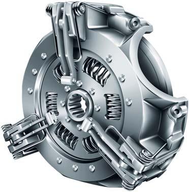
8 Single clutch with independent drive for P.T.O. (split torque). Cover housing. Pressure plate. Diaphragm spring (with reinforced fingers). Fixed P.T.O. hub. Rivet. Fulcrum ring. Tangential strap. Headed rivet
. Diaphragm spring. Coil spring. P.T.O.")

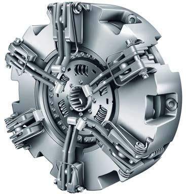
9 Combined clutch for tractors (special design) 0 0. Cover housing. P.T.O. pressure plate. Flywheel plate. Pressure plate (transmission). Diaphragm spring. Coil spring. P.T.O. disc (with organic friction). Pivot pin. Fixing hole 0. Shipping bolt. P.T.O. adjusting screw. Link. Clutch lever. Anti-rattle spring. Lever adjustment screw. Balance hole. Rivet


10 Double clutch with independent P.T.O. 0. Cover housing. Main drive pressure plate. P.T.O. pressure plate. Diaphragm spring. Main drive clutch disc (with sintered pads and torsion damper). Main drive lever. P.T.O. lever. P.T.O. lever eyebolt. Transmission lever elbow 0. Adjusting screw. Lock nut. Adjusting nut. Anti-rattle spring. Pivot pin. Fulcrum ring
. Diaphragm spring.")
 (with sintered pads and torsion damper). Main drive lever. Transmission lever eyebolt.")
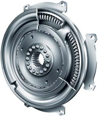
11 Twin plate clutch for transmission drive 0. Cover housing. Main drive pressure plate (transmission side). Main drive pressure plate (flywheel side). Diaphragm spring. Main drive clutch disc (transmission side) (with sintered pads and torsion damper). Main drive clutch disc (flywheel side) (with sintered pads and torsion damper). Main drive lever. Transmission lever eyebolt. Transmission lever elbow 0. Adjusting screw. Lock nut. Adjusting nut. Anti-rattle spring. Pivot pin. Fulcrum ring. Rivet. Balance hole. Disc spline


12 Single safety P.T.O. clutch with fixed transmission damper 0 0. Cover housing. P.T.O. pressure plate. P.T.O. coil spring. Fixed transmission damper. Friction device. P.T.O. lever. Pivot pin. Anti-rattle spring. Adjusting nut 0. Transmission damper spring. P.T.O. lever eyebolt. Rivet 0

13 Double clutch with safety P.T.O Cover housing. Main drive pressure plate. P.T.O. pressure plate. Diaphragm spring. Main drive disc (with sintered pads and torsion damper). Pivot pin. Main drive lever. P.T.O. lever. Fulcrum ring 0. P.T.O. lever eyebolt. Transmission lever elbow. Adjusting screw. Lock nut. Adjusting nut. Anti-rattle spring. Coil spring. Balance hole


14 Front P.T.O. clutch Housing cover plate. Diaphragm spring. Separator discs. Drive discs (with sintered pads). Lower pressure plate. Secondary drive hub. Support bearing. Primary drive hub. Rivet 0. Housing bolt. Fulcrum ring. Coil spring 0
. Damper housing.")

15 Long travel torsion damper. Location plate (primary). Damper housing. Drive shaft location flange (secondary). Arc spring. Friction device. Location holes. Rivet. Central carrier plate (secondary)
. Torsion springs (third stage). Friction device. Location hole. Rivet 0. Splined drive hub.")
16 Axial spring torsion damper 0 0. Location plate (primary). Carrier plate (secondary). Sensor wings. Torsion springs (idle). Torsion springs (second stage). Torsion springs (third stage). Friction device. Location hole. Rivet 0. Splined drive hub. Backplate


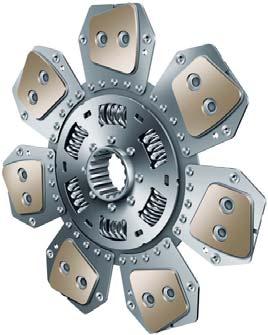
17 Drive disc (with sintered or organic friction). Friction pad. Friction backplate. Torsion damper spring. Splined drive hub. Carrier plate. Cushioned friction carrier plate. Friction device. Rivet. Cushion rivet


18 Concentric Slave Cylinder (CSC). Housing. Release bearing. Hydraulic port. Piston. Piston seal. Pre-load spring. Plastic dust shield
19 Notes

 E-Mail:")
 Ltd")
20 00 00 / Schaeffler Automotive Aftermarket GmbH & Co KG Tractor Clutch Technical Hotline (UK): Non-UK callers please dial + (0) hfd-pm@schaeffler.com Schaeffler Automotive Aftermarket (UK) Ltd Holme Lacy Road, Rotherwas, Hereford, HR BQ Phone: + (0)
Failure Diagnosis. LuK s guide to troubleshooting clutch system failures and malfunctions
 Failure Diagnosis LuK s guide to troubleshooting clutch system failures and malfunctions The content of this brochure shall not be legally binding and is for information purposes only. To the extent legally
Failure Diagnosis. LuK s guide to troubleshooting clutch-system failures and malfunctions. commercial vehicles
 Failure Diagnosis LuK s guide to troubleshooting clutch-system failures and malfunctions commercial vehicles Contents LuK tips on avoiding clutch system failures and malfunctions 4 5 Clutch fails to disengage
Clutch Diagnosis - Causes of Failure
 Clutch Diagnosis - Causes of Failure Guide Tube wear, Spline wear, Mainshaft Bearing wear Worn Flywheel Bearing, ridged or heat damaged Flywheel surface Worn/siezed Release Arm pivots, friction lining
CLUTCH F A U L T D I A GNOSIS GUIDE
 LOSS OF DRIVE Loss of drive Facing material broken CLUTCH F A U L T D I A GNOSIS GUIDE Friction material damaged prior to or during fitment Overheating due to slip Incorrect clutch fitted for the application.
Clutches for Automobiles and Light Trucks
 Clutches for Automobiles and Light Trucks What does the Clutch do? Connects the engine torque to transmission when ENGAGED Unhooks engine from transmission when DISENGAGED Where is the driver s foot when
Tech Note Truck 14 & 15.5 Twin Plate Cast Iron Type Installation Guidelines
 1. (14 & 15.5 ) Check condition of the flywheel. Grind to resurface or replace flywheel. Surface MUST BE machined or premature clutch failure can occur. Flywheel depth must be 2.938 (74.62mm) for 14 (350mm)
Troubleshooting. Pull Type Clutches - Poor Release
 Troubleshooting Pull Type Clutches - Poor Release Complaint Possible Causes Corrective Action Poor Release Intermediate plate sticking on drive lugs due to cocked drive pins (AS and EP 1402 only) (see
CLUTCH 6-1 CLUTCH CONTENTS
 TJ CLUTCH 6-1 CLUTCH CONTENTS page GENERAL INFORMATION CLUTCH COMPONENTS... 1 INSTALLATION METHODS AND PARTS USAGE... 1 DESCRIPTION AND OPERATION CLUTCH OPERATION... 1 DIAGNOSIS AND TESTING DIAGNOSTIC
CLUTCH 6-1 CLUTCH CONTENTS
 Z CLUTCH 6-1 CLUTCH CONTENTS page page CLUTCH DIAGNOSIS... 2 CLUTCH SERVICE... 9 CLUTCH COMPONENTS MECHANICAL COMPONENTS The clutch mechanism in Grand Cherokee models with manual transmission consists
Diagnistic Information
 Diagnistic Information DIAGNOSTIC INFORMATION Clutch Function Vehicles equipped with manual transmissions contain clutch systems that connect and disconnect the engine and transmission. The clutch system
Self-Adjusting Clutch (SAC) Technology Special tools / User instructions
 Technology Special tools / User instructions") Self-Adjusting Clutch (SAC) Technology Special tools / User instructions The content of this brochure shall not be legally binding and is for information purposes only. To the extent legally permissible,
Self-Adjusting Clutch (SAC) Technology Special tools / User instructions The content of this brochure shall not be legally binding and is for information purposes only. To the extent legally permissible,
CLUTCH 6-1 CLUTCH TABLE OF CONTENTS
 PL CLUTCH 6-1 CLUTCH TABLE OF CONTENTS page DESCRIPTION AND OPERATION MODULAR CLUTCH ASSEMBLY....1 CLUTCH CABLE...1 CLUTCH INTERLOCK/UPSTOP SWITCH....1 DIAGNOSIS AND TESTING CLUTCH SYSTEM DIAGNOSIS...2
FAG Wheel Bearing Repair Solution for Light Commercial Vehicles
 FAG Wheel Bearing Repair Solution for Light Commercial Vehicles Mercedes-Benz Sprinter, Viano, Vito and Volkswagen Crafter Front Axle The content of this brochure shall not be legally binding and is for
CLUTCH. Section IV DATA AND SPECIFICATIONS CHRYSLER SERVICE MANUAL. Page. Clutch Pedal Adjustment 74. Clutch Disassembly 77. Clutch Assembly 78
 CLUTCH 73 Section IV CLUTCH Page Clutch Pedal Adjustment 74 Clutch Disassembly 77 Clutch Assembly 78 Service Diagnosis 81 DATA AND SPECIFICATIONS MODEL TYPE 1376 (Borg-Beck) Single Plate, Dry Disc FACINGS
Introduction to Manual Transmissions & Transaxles
 Section 1 Introduction to Manual Transmissions & Transaxles Learning Objectives: 1. Identify the purpose and operation of transmissions. 2. Describe torque and torque multiplication. 3. Determine gear
LuK Repair Solution for manual transmissions. Disassembly and assembly Special tool/failure diagnosis VW 02J
 LuK Repair Solution for manual transmissions Disassembly and assembly Special tool/failure diagnosis VW 02J The content of this brochure shall not be legally binding and is for information purposes only.
ENGINE CLUTCH CONTENTS OF THIS SECTION
 ENGINE CLUTCH 6C-l ENGINE CLUTCH CONTENTS OF THIS SECTION SUBJECT General Description Periodic Service Adjustments on Car Removal of Clutch Inspection of Clutch Parts Installation of Clutch Specifications
Clutch System Troubleshooting Guide-Service Tips
 DESCRIPTION AND OPERATION Clutch System The purpose of the clutch is to connect and disconnect a manually operated transmission and the remainder of the powertrain system from the engine. This permits
page CLUTCH DIAGNOSIS 2
 6-1 CONTENTS page DIAGNOSIS 2 COMPONENTS MECHANICAL COMPONENTS The clutch mechanism in A D models with a gas or diesel engine consists of a single, dry-type clutch disc and a diaphragm style clutch cover.
LuK Repair Solution for manual transmissions. Disassembly and assembly Special tool/failure diagnosis PSA MA
 LuK Repair Solution for manual transmissions Disassembly and assembly Special tool/failure diagnosis PSA MA The content of this brochure shall not be legally binding and is for information purposes only.
1992 Clutch. Eclipse, Expo/Expo LRV, Galant, Mirage, Precis, 3000GT
 Article Text ARTICLE BEGINNING 1992 Clutch Eclipse, Expo/Expo LRV, Galant, Mirage, Precis, 3000GT DESCRIPTION All clutches are single disc type. Pressure plate assembly uses a diaphragm spring to engage
ATASA 5 th Study Guide Chapter 36 Pages Clutches 74 Points. Clutches. Be Certain to Read the Summary
 ATASA 5 th Study Guide Chapter 36 Pages 1071 1091 74 Points Be Certain to Read the Summary 1. The provides a mechanical coupling between the engine s & the transmission s shaft. The clutch allows the engine
BRAKE SYSTEM Return To Main Table of Contents
 BRAKE SYSTEM Return To Main Table of Contents GENERAL... 2 BRAKE PEDAL... 10 MASTER CYLINDER... 13 BRAKE BOOSTER... 16 BRAKE LINE... 18 PROPORTIONING VALVE... 19 FRONT DISC BRAKE... 20 REAR DRUM BRAKE...
Symptom Suspect Area See page 5. Engine mounting (Loosen) 6. Clutch disc assy (Runout is excessive) 7. Clutch disc assy (Oily)
 6. Clutch disc assy (Runout is excessive) 7. Clutch disc assy (Oily)") CLUTCH CLUTCH SYSTEM (MTM) PROBLEM SYMPTOMS TABLE HINT: CLUTCH SYSTEM (MTM) Use the table below to help you find the cause of the problem. The numbers indicate the priority of the likely cause of the problem.
CLUTCH CLUTCH SYSTEM (MTM) PROBLEM SYMPTOMS TABLE HINT: CLUTCH SYSTEM (MTM) Use the table below to help you find the cause of the problem. The numbers indicate the priority of the likely cause of the problem.
1994 Mazda MX-5 Miata. CLUTCH 1994 Clutch
 CLUTCH 1994 Clutch DESCRIPTION Miata uses a hydraulically operated clutch. HYDRAULIC SYSTEM BLEEDING 1. Remove bleeder screw cap, located at clutch release cylinder. Install vinyl hose onto bleeder screw.
Clutch Installation Guide
 Clutch Installation Guide 0 STOP! READ CAREFULLY BEFORE INSTALLING CLUTCH This clutch must be installed by a qualified installer. Improper installation or failure to replace or resurface the flywheel,
CLUTCH PREPARATION Union Nut Wrench 10 mm Clutch Guide Tool Input Shaft Front Bearing Puller
 CLUTCH CL1 CL2 PREPARATION SST (SPECIAL SERVICE TOOLS) CLUTCH PREPARATION 0902300100 Union Nut Wrench 10 mm Clutch line 0930100110 Clutch Guide Tool 0930335011 Input Shaft Front Bearing Puller 0930430012
Clutch Clut Fundament Fundamen als t Chapter 69
 Clutch Fundamentals Chapter 69 Objectives Describe the basic clutch parts Explain the operation of the clutch Compare differences in clutch hdesign Describe the different methods of releasing the clutch
CLUTCH Nissan 240SX DESCRIPTION PEDAL HEIGHT & FREE PLAY ADJUST CLUTCH ASSEMBLY R & I Clutch. Pathfinder, Pickup, 240SX, 300ZX
 CLUTCH 1990 Nissan 240SX 1990 Clutch Pathfinder, Pickup, 240SX, 300ZX DESCRIPTION Clutch is of dry, single disc type, with a diaphragm spring type pressure plate. Clutch release bearing is prelubricated.
CARBONETIC Carbon Clutch operating instructions
 ACROSS USA INC www.carbonetic.net TEL:310-635-3555 CARBONETIC Carbon Clutch operating instructions Thank you very much for your purchase of the CARBONETIC carbon clutch. Please read these instructions
Self-Adjust Clutch Installation Guide
 Self-Adjust Clutch Installation Guide 0 STOP! READ CAREFULLY BEFORE INSTALLING CLUTCH This clutch must be installed by a qualified installer. Improper installation or failure to replace or resurface the
Clutch cover Type Diaphragm spring strap. Clutch pedal Type Suspended type. Maximum operating travel
 000000 043 1. SPECIFICATION Operating type Description Hydraulic type Specification Clutch cover Type Diaphragm spring strap Adjusting type Clutch pedal Type Suspended type Max. operating travel Pedal
BASIC BRAKE SYSTEM GROUP 35A 35A-1 CONTENTS GENERAL DESCRIPTION... 35A-3 BASIC BRAKE SYSTEM DIAGNOSIS 35A-6
 35A-1 GROUP 35A BASIC BRAKE SYSTEM CONTENTS GENERAL DESCRIPTION......... 35A-3 DIAGNOSIS 35A-6 INTRODUCTION..................... 35A-6 DIAGNOSTIC TROUBLESHOOTING STRATEGY......................... 35A-6
ATS metal clutch (twin / triple) instruction manual for Nissan 350Z w/ HR motor 12 pages
 instruction manual for Nissan 350Z w/ HR motor 12 pages") ATS metal clutch (twin / triple) instruction manual for Nissan 350Z w/ HR motor 12 pages This instruction is provided by Performance Partners Intl 1 ATS Clutch operating instructions Thank you very much
ATS metal clutch (twin / triple) instruction manual for Nissan 350Z w/ HR motor 12 pages This instruction is provided by Performance Partners Intl 1 ATS Clutch operating instructions Thank you very much
DESCRIPTION AND OPERATION > CLUTCH CONTROLS
 Page 1 of 17 2004 Ford Mustang 3.9L Eng Base Service Manual: CLUTCH CONTROLS Print Date: DESCRIPTION AND OPERATION > CLUTCH CONTROLS Fig 1: Identifying Clutch Controls Components Page 2 of 17 The clutch
2006 Hyundai Tiburon GT
 Fig. 5: Identifying Clutch Cover & Disc Component With Torque Specifications REMOVAL 1. Drain the clutch fluid and transaxle gear oil. 2. Remove the transaxle assembly. 3. Insert the special tool (09411-25000)
SACHS Clutches The Intelligent Choice for the Long Haul
 SACHS Clutches The Intelligent Choice for the Long Haul Twin XTend Clutch Installation Objectives: Identification Operation Tools Installation Troubleshooting Identification 15.5 Self Adjusting Clutch
GROUP 35A 35A-1 CONTENTS GENERAL DESCRIPTION... 35A-3 BASIC BRAKE SYSTEM DIAGNOSIS 35A-6 HYDRAULIC BRAKE BOOSTER (HBB) DIAGNOSIS...
 DIAGNOSIS...") 35A-1 GROUP 35A CONTENTS GENERAL DESCRIPTION......... 35A-3 DIAGNOSIS 35A-6 INTRODUCTION..................... 35A-6 DIAGNOSTIC TROUBLESHOOTING STRATEGY......................... 35A-6 SYMPTOM CHART...................
35A-1 GROUP 35A CONTENTS GENERAL DESCRIPTION......... 35A-3 DIAGNOSIS 35A-6 INTRODUCTION..................... 35A-6 DIAGNOSTIC TROUBLESHOOTING STRATEGY......................... 35A-6 SYMPTOM CHART...................
CLUTCH CONTENTS SERVICE DIAGNOSIS. (a) Worn or damaged disc assembly. (b) Grease or oil on disc facings. (c) Improperly adjusted cover assembly.
 Worn or damaged disc assembly. (b) Grease or oil on disc facings. (c) Improperly adjusted cover assembly.") CLUTCH CONTENTS -GROUP 6 Page CLUTCH HOUSING ALIGNMENT... 6 CLUTCH PEDAL FREE PLAY 1 CLUTCH RELEASE BEARING 5 CLUTCH RELEASE FORK... 5 CLUTCH SERVICING 2 PILOT BUSHING CRANKSHAFT TO TRANSMISSION DRIVE
CLUTCH CONTENTS -GROUP 6 Page CLUTCH HOUSING ALIGNMENT... 6 CLUTCH PEDAL FREE PLAY 1 CLUTCH RELEASE BEARING 5 CLUTCH RELEASE FORK... 5 CLUTCH SERVICING 2 PILOT BUSHING CRANKSHAFT TO TRANSMISSION DRIVE
Have a good trip - with John Deere clutches!
 Parts Information Have a good trip - with John Deere clutches! The clutch disc is the central connecting element of the clutch. Together with the flywheel and the clutch pressure plate it forms a friction
1. General GENERAL CL-2
 SYSTEM GENERAL 1. General The clutch is of a dry, single plate type with a diaphragm spring. The clutch is a push type clutch. When the pedal is depressed, the release bearing will press the center of
LuK Clutch Course and Failure Diagnosis. Introduction to Clutch Technology Guidelines for Evaluating Clutch System Malfunctions in Commercial Vehicles
 LuK Clutch Course and Failure Diagnosis Introduction to Clutch Technology Guidelines for Evaluating Clutch System Malfunctions in Commercial Vehicles The content of this brochure is not legally binding
Service Manual. LL30002 Rev. 7/03. HEAVY DUTY PUSH/PULL TYPE CLUTCHES
 Service Manual LL30002 Rev. 7/03 HEAVY DUTY PUSH/PULL TYPE CLUTCHES www.haldex.com Table of Contents Section One - Push Type Clutches Clutch Assembly Cutaway Detail............................1 Clutch
 www.clubsuprafrance.com CLUTCH 1996 Toyota Supra 1995-96 Clutch Supra DESCRIPTION The single, dry-type disc clutch uses a hydraulicallyoperated master cylinder with a clutch release cylinder mounted on
Parking brake Mechanical brake acting on rear wheels
 11 Brake System 11.1 General SPECIFICATIONS EJTC0010 Master cylinder Type Tandem type I.D. mm(in.) 20.64 mm (0.813 in.) Fluid level warning sensor Provided Brake booster Type Vacuum Boosting ratio 4.0
20. TROUBLESHOOTING ENGINE DOES NOT START OR IS HARD TO START XL200
 20. ENGINE DOES NOT START OR IS HARD TO START 20-1 ENGINE LACKS POWER 20-2 POOR PERFORMANCE AT LOW AND IDLE SPEED 20-3 POOR PERFORMANCE AT HIGH SPEED 20-4 POOR HANDLING 20-4 ENGINE DOES NOT START OR IS
Advanced Auto Tech. ASE A 3 Test Preparation Clutch & Drive Line Service
 Advanced Auto Tech ASE A 3 Test Preparation Clutch & Drive Line Service The clutch and the drive line both have their own unique symptoms and noises, separate from the transmissions used to change torque
A clever combination. Repair solutions for driveline.
 A clever combination. Repair solutions for driveline. The content of this brochure is not legally binding and is solely intended for information purposes. Where legally permissible, all liability on the
Self-Adjusting Clutch (SAC) Technology Special tool/user instructions
 Technology Special tool/user instructions") Self-Adjusting Clutch (SAC) Technology Special tool/user instructions The content of this brochure is not legally binding and is solely intended for information purposes. Where legally permissible, all
Self-Adjusting Clutch (SAC) Technology Special tool/user instructions The content of this brochure is not legally binding and is solely intended for information purposes. Where legally permissible, all
DRAGON CLAW SHELBY 26 SPLINE
 DRAGON CLAW 13-14 5.4 SHELBY 26 SPLINE *This Kit Requires a Min. 1 ⅝ in. Working Input Shaft Splines. *Professional Installation recommended *Power/Air tools NOT advised 1. Remove transmission assembly
CLUTCH SECTION CL CONTENTS C TRANSMISSION/TRANSAXLE CL-1
 C TRANSMISSION/TRANSAXLE SECTION CL A B CLUTCH CL D CONTENTS E PRECAUTIONS... 2 Precautions for Supplemental Restraint System (SRS) AIR BAG and SEAT BELT PRE-TEN- SIONER... 2 Service Notice or Precautions...
CLUTCH SECTION CL CONTENTS C TRANSMISSION/TRANSAXLE CL-1
 C TRANSMISSION/TRANSAXLE SECTION CL A B CLUTCH CL D CONTENTS E PRECAUTIONS... 2 Precautions for Supplemental Restraint System (SRS) AIR BAG and SEAT BELT PRE-TEN- SIONER... 2 Service Notice or Precautions...
SECTION D REAR SUSPENSION. Section Description Page D.1. REMOVING AND REFITTING A REAR SUSPENSION UNIT 5
 SECTION D REAR SUSPENSION Section Description Page D.1. REMOVING AND REFITTING A REAR SUSPENSION UNIT 5 D.2. REMOVING AND REFITTING THE COMPONENTS OF THE REAR SUSPENSION 8 D.3. CHECKING AND OVERHAULING
12. FRONT WHEEL/FRONT BRAKE/
 12 4.5kgm 0.9kg-m 4.5kg-m 12-0 SERVICE INFORMATION... 12-1 HYDRAULIC BRAKE... 12-10 TROUBLESHOOTING... 12-2 FRONT SHOCK ABSORBER... 12-16 FRONT WHEEL... 12-3 STEERING HANDLEBAR... 12-19 FRONT BRAKE...
CAUTION. Hydraulic Brakes. Braking Systems - Hydraulic
 Hydraulic Brakes Dexter offers several varieties of hydraulic trailer brakes. Your vehicle may be equipped with drum brakes or disc brakes. The hydraulic brakes on your trailer are much like those on your
SERVICE BRAKES GROUP 35A 35A-1 CONTENTS GENERAL DESCRIPTION... 35A-2 BRAKE PEDAL... 35A-22 BASIC BRAKE SYSTEM DIAGNOSIS 35A-3
 35A-1 GROUP 35A CONTENTS GENERAL DESCRIPTION 35A-2 BASIC BRAKE SYSTEM DIAGNOSIS 35A-3 INTRODUCTION TO BASIC BRAKE SYSTEM DIAGNOSIS 35A-3 BASIC BRAKE SYSTEM DIAGNOSTIC TROUBLESHOOTING STRATEGY 35A-3 SYMPTOM
SECTION 5B MANUAL TRANSMISSION TABLE OF CONTENTS
 SECTION 5B MANUAL TRANSMISSION TABLE OF CONTENTS General Description and Operation... 5B-2 Shift Lever... 5B-2 Transmission Assembly... 5B-2 Specifications... 5B-3 Diagnostic Information and Procedures...
Transmission Input Bearing Retainer
 34 Transmission Input Bearing Retainer Clutch Cover / Intermediate Plate Fig 11 Failure - Damaged Sleeve Bushing Failure to center the input shaft with the sleeve of the release bearing assembly, when
CLUTCH SECTION CL CONTENTS TRANSMISSION & DRIVELINE CL-1 SYMPTOM DIAGNOSIS... 2 REMOVAL AND INSTALLATION...16 PRECAUTION... 4 PREPARATION...
 TRANSMISSION & DRIVELINE SETION L A LUTH L ONTENTS E SYMPTOM DIAGNOSIS... 2 NOISE, VIRATION AND HARSHNESS (NVH) TROULESHOOTING... 2 NVH Troubleshooting hart...2 PREAUTION... 4 PREAUTIONS... 4 Precaution
HORSTMAN GREASED LIGHTNING CLUTCH
 HORSTMAN GREASED LIGHTNING CLUTCH Horstman s Greased Lightning (GL) clutch is designed for ultra high performance, and requires expert setup and a serious commitment to maintenance. Warning!!! 1. Clutch
DIM Drive Train Systems
 2014 NATEF JOB TASKS COMPLETION REQUIREMENT: P1-95% P2-70% P3-25% Student Name: DETAILED COURSE CONTENT II. DRIVE TRAIN A. CLUTCH -- The student will be able to: P1 P2 P3 Level Date 1. Identify causes
ATTACHMENTS COMPONENT LOCATION
 42-Inch Mower Deck ATTACHMENTS COMPONENT LOCATION C D E F G H I H G M A B J O K L N M J A - Gage Wheel (Left Front) B - Belt Cover C - Primary Drive Belt D - Flat Idler (fixed) E - Gage Wheel (Right Front)
TSM54/52 MANUAL TRANSMISSION
 3B-1 SECTION 00 3B TSM54/52 MANUAL TRANSMISSION Table of Contents GENERAL INFORMATION... 3B-3 Overview... 3B-3 Specifications... 3B-4 System components... 3B-5 Shifting mechanism... 3B-17 Diagnostic information
Contents c mm Ø Cerametallic & Organic Drive Plate Hub Spline Details H e l i x
 Contents Part Number Legend... 2 The HELIX Racing Clutch Range... 4 Clutch Terminology... 5 Clutch Fitting & Flywheels... 6 Release Bearings... 7 Concentric Slave Cylinder Release Bearings... 8 Clutch
DIAGNOSIS AND TESTING Procedure revision date: 05/18/2000. SYMPTOM CHART TRANSMISSION, MANUAL Condition Possible Source Action
 SYMPTOM CHART TRANSMISSION,... SYMPTOM CHART TRANSMISSION, MANUAL (TRANSMISSION, MANUAL, M5OD) Section 07 03: Transmission, Manual, M5OD 1996 Aerostar/Ranger/Explorer Workshop Manual DIAGNOSIS AND TESTING
AUT 231 (A3) MANUAL TRANSMISSION/TRANSAXLE AND DRIVETRAIN
 MANUAL TRANSMISSION/TRANSAXLE AND DRIVETRAIN") AUT 231 (A3) MANUAL TRANSMISSION/TRANSAXLE AND DRIVETRAIN COURSE DESCRIPTION: Prerequisites: TRN 120 Corequisites: None This course covers the operation, diagnosis, and repair of manual transmissions/transaxles,
AUT 231 (A3) MANUAL TRANSMISSION/TRANSAXLE AND DRIVETRAIN COURSE DESCRIPTION: Prerequisites: TRN 120 Corequisites: None This course covers the operation, diagnosis, and repair of manual transmissions/transaxles,
SERVICE INFORMATION 11-1 FRONT WHEEL/SUSPENSION/ STEERING XL FRONT WHEEL 11 7 FORK STEERING STEM 11 18
 XL200 11. FRONT WHEEL/SUSPENSION/ STEERING SERVICE INFORMATION 11 1 TROUBLESHOOTING 11 2 HANDLEBAR 11 3 FRONT WHEEL 11 7 FORK 11 11 STEERING STEM 11 18 SERVICE INFORMATION GENERAL A contaminated brake
CLUTCH SECTION CL CONTENTS C TRANSMISSION/TRANSAXLE CL-1
 CLUTCH C TRANSMISSION/TRANSAXLE SECTION CL A B CLUTCH CL D CONTENTS E PRECAUTIONS... 2 Caution... 2 PREPARATION... 3 Special Service Tools... 3 Commercial Service Tools... 3 NOISE, VIBRATION AND HARSHNESS
PO Box 645, Stockton, Missouri, FAX superiorgearbox.com
 I000-7000-D0447-A 4/7/05 1 SAFETY PRECAUTIONS CAUTION Please read this entire document prior to operating the gear drive. Gear drive failure and / or injury to operators may be caused by improper installation,
SUSPENSION 2-1 SUSPENSION CONTENTS
 TJ SUSPENSION 2-1 SUSPENSION CONTENTS page ALIGNMENT... 1 FRONT SUSPENSION... 5 page REAR SUSPENSION... 12 ALIGNMENT INDEX page GENERAL INFORMATION WHEEL ALIGNMENT... 1 DIAGNOSIS AND TESTING SUSPENSION
SUSPENSION 2-1 SUSPENSION CONTENTS
 TJ SUSPENSION 2-1 SUSPENSION CONTENTS page ALIGNMENT... 1 FRONT SUSPENSION... 6 page REAR SUSPENSION... 13 ALIGNMENT INDEX page DESCRIPTION AND OPERATION WHEEL ALIGNMENT... 1 DIAGNOSIS AND TESTING SUSPENSION
SUSPENSION 2-1 SUSPENSION TABLE OF CONTENTS
 DN SUSPENSION 2-1 SUSPENSION TABLE OF CONTENTS page ALIGNMENT... 1 FRONT SUSPENSION - 4x2... 6 page FRONT SUSPENSION - 4x4... 14 REAR SUSPENSION... 23 ALIGNMENT TABLE OF CONTENTS page AND OPERATION WHEEL
15.Main Shaft Assembly
 15.Main Shaft Assembly A: REMOVAL 1) Remove the manual transmission assembly from vehicle. 2) Remove the transfer case with extension case assembly.
Lotus Service Notes Section QA
 CLUTCH SECTION QA Sub-Section Page General Description QA.1 3 Clutch Pedal QA.2 4 Clutch Master Cylinder, Slave Cylinder, Clutch Damper & Hydraulic Lines QA.3 5 Clutch Bleeding Procedure QA.4 8 Clutch
SPECIAL TOOLS Dodge Pickup 5.9L Eng R3500. Fig 1: Identifying Remover C-3985-B (Special Tool) 9/6/13 Printer Friendly View
 9/6/13 Printer Friendly View") Procedures 2003 Dodge Pickup 5.9L Eng R3500 manual transmission SPECIAL TOOLS Fig 1: Identifying Remover C-3985-B (Special Tool) www2.prodemand.com/print/index?content=tabs&module=true&tab=true&terms=true&ymms=false&classname=
Procedures 2003 Dodge Pickup 5.9L Eng R3500 manual transmission SPECIAL TOOLS Fig 1: Identifying Remover C-3985-B (Special Tool) www2.prodemand.com/print/index?content=tabs&module=true&tab=true&terms=true&ymms=false&classname=
SUSPENSION 2-1 SUSPENSION TABLE OF CONTENTS
 XJ SUSPENSION 2-1 SUSPENSION TABLE OF CONTENTS page ALIGNMENT... 1 FRONT SUSPENSION... 7 page REAR SUSPENSION... 16 ALIGNMENT TABLE OF CONTENTS page AND WHEEL ALIGNMENT...1 DIAGNOSIS AND TESTING SUSPENSION
SUSPENSION 2-1 SUSPENSION CONTENTS
 ZJ SUSPENSION 2-1 SUSPENSION CONTENTS page ALIGNMENT... 1 FRONT SUSPENSION... 6 page REAR SUSPENSION... 14 ALIGNMENT INDEX page GENERAL INFORMATION WHEEL ALIGNMENT... 1 DIAGNOSIS AND TESTING SUSPENSION
INSTALLATION INSTRUCTIONS
 INSTALLATION INSTRUCTIONS PERFORMANCE AT THE WHEELS KITS W156-6 & W156-7 1965-74 MOPAR B & E BODY Thank you for choosing STAINLESS STEEL BRAKES CORPORATION for your braking needs. Pleases take the time
DRAGON CLAW PRE 86 BIG BLOCK CHEVY 10 SPLINE
 DRAGON CLAW PRE 86 BIG BLOCK CHEVY 10 SPLINE *This Kit Requires a Min. 1 ⅝ in. Working Input Shaft Splines. *Professional Installation recommended *Power/Air tools NOT advised 1. Inspect input shaft splines
Diagnostic Procedures
 Section 6 Diagnostic Procedures Learning Objectives: 1. Describe manual transmission, transaxle and transfer case component inspection and diagnostic procedures 2. Identify clutch component inspection
Module 6: Air Foundation Brakes
 Air Brakes Terms and Definitions Basic Components That Make Up Air Foundation Brakes Types of Air Foundation Brakes Parts of a Cam Foundation Brake Parts of a Wedge Foundation Brake Parts of a Disc Foundation
REAR SUSPENSION GROUP CONTENTS GENERAL DESCRIPTION REAR SUSPENSION DIAGNOSIS LOWER ARM AND TOE CONTROL ARM ASSEMBLY...
 34-1 GROUP 34 CONTENTS GENERAL DESCRIPTION........... 34-2 DIAGNOSIS.... 34-2 INTRODUCTION....................... 34-2 TROUBLESHOOTING STRATEGY........ 34-2 SYMPTOM CHART..................... 34-3 SYMPTOM
GROUP 6 CLUTCH CONTENTS SPECIFICATIONS
 GROUP 6 CLUTCH CONTENTS Page CLUTCH 6-1 Specifications.... 1 Transmission Main Drive Pinion Pilot Bushing... 5 Special Tools. 1 Clutch Release Bearing 6 Torque Reference 1 Torque Shaft and Bearings...
John Deere. MODEL: 4320 Tractor JD-S-TM1029
 John Deere MODEL: 4320 Tractor THIS IS A MANUAL PRODUCED BY JENSALES INC. WITHOUT THE AUTHORIZATION OF JOHN DEERE OR IT'S SUCCESSORS. JOHN DEERE AND IT'S SUCCESSORS ARE NOT RESPONSIBLE FOR THE QUALITY
For the most current information, visit the Roadranger web site at
 Eaton Fuller Heavy Duty Transmissions 8 - Speed Direct Drivers Instructions TRDR-0310 March 2004 For the most current information, visit the Roadranger web site at www.roadranger.com Warnings Warnings
SECTION 4A HYDRAULIC BRAKES
 SECTION 4A HYDRAULIC BRAKES Caution: Disconnect the negative battery cable before removing or installing any electrical unit or when a tool or equipment could easily come in contact with exposed electrical
Installation Operation Maintenance. LSSN Butterfly Valve AGA Approved 50MM - 150MM. QAD#IM6055.REVA
 LSSN Butterfly Valve Installation Operation Maintenance Licence Number: 5326 www.challengervalves.com.au 1 Index 1. INTRODUCTION 1.1 Design Features 3 1.2 Flange and Pipe Compatibility 4 1.3 Operating
2010 Toyota Prius Repair Manual
 REMOVAL 1. DISABLE BRAKE CONTROL (a) Wait at least 2 minutes after the power switch off. NOTICE: When the brake pedal is depressed or the door courtesy switch is turned on even if the power switch is off,
PO Box 645, Stockton, Missouri, FAX superiorgearbox.com W D0446-A 4/1/05 1
 W000-7000-D0446-A 4/1/05 1 SAFETY PRECAUTIONS CAUTION Please read this entire document prior to operating the gear drive. Gear drive failure and / or injury to operators may be caused by improper installation,
GROUP 35A 35A-1 CONTENTS GENERAL DESCRIPTION... 35A-3 BASIC BRAKE SYSTEM DIAGNOSIS 35A-4 SPECIAL TOOLS... 35A-16 BRAKE PEDAL...
 35A-1 GROUP 35A CONTENTS GENERAL DESCRIPTION......... 35A-3 DIAGNOSIS 35A-4 INTRODUCTION TO DIAGNOSIS........................ 35A-4 DIAGNOSTIC TROUBLESHOOTING STRATEGY...... 35A-4 SYMPTOM CHART...................
CLUTCH SECTION CL CONTENTS C TRANSMISSION/TRANSAXLE CL-1
 CLUTCH C TRANSMISSION/TRANSAXLE SECTION CL A B CLUTCH CL D CONTENTS E PRECAUTIONS... 2 Caution... 2 PREPARATION... 3 Special Service Tools... 3 Commercial Service Tools... 3 NOISE, VIBRATION AND HARSHNESS
18. REAR WHEEL/SUSPENSION
 18. REAR WHEEL/SUSPENSION SYSTEM COMPONENTS 182 REAR AXLE/BEARING HOLDER 187 SERVICE INFORMATION 183 REAR SHOCK ABSORBER 1816 TROUBLESHOOTING 186 SHOCK LINKAGE 1818 REAR WHEEL 187 SWINGARM 1820 181 SYSTEM
TRANSMISSION AND TRANSFER CASE
 DR TRANSMISSION AND TRANSFER CASE 21-1 TRANSMISSION AND TRANSFER CASE TABLE OF CONTENTS page MANUAL TRANSMISSION- G56- SERVICE INFORMATION...1 MANUAL TRANSMISSION- GETRAG 238- SERVICEINFORMATION...69 MANUAL
SECTION steering mechanism
 07-302.01/ 1 2011MR17 SECTION 07-302.01 GENERAL Description See Figure 1. The includes the steering wheel (1), the steering column, the miter box (3), the steering shafts (2 and 4), and the drag link (7).
22-1 GROUP 22 MANUAL TRANSAXLE CONTENTS MANUAL TRANSAXLE... 22A MANUAL TRANSAXLE OVERHAUL... 22B
 22-1 GROUP 22 MANUAL TRANSAXLE CONTENTS............................... 22A OVERHAUL..................... 22B 22A-2 GROUP 22A MANUAL TRANSAXLE CONTENTS GENERAL DESCRIPTION......... 22A-3 DIAGNOSIS 22A-6
Series 1000 and Cutout
 17.15.Remove the belt from the tractor. NOTE: There were a small number of tractors made using a CVT drive and a 2-speed (L-H-N-R) GT transaxle. The belt must pass over the center mounted gear selector
Service Manual. MF2135 Industrial
 Massey Harris Massey Ferguson Service Manual MF2135 Industrial Service Manual THIS IS A MANUAL PRODUCED BY JENSALES INC. WITHOUT THE AUTHORIZATION OF MASSEY HARRIS MASSEY FERGUSON OR IT S SUCCESSORS. MASSEY
21A-1 CLUTCH CONTENTS CLUTCH... CLUTCH OVERHAUL
 21A-1 CLUTCH CONTENTS CLUTCH... 21A CLUTCH OVERHAUL... 21B 21A-2 CLUTCH CONTENTS GENERAL INFORMATION... 3 SERVICE SPECIFICATIONS... 3 LUBRICANTS... 3 ON-VEHICLE SERVICE... 3 Clutch Pedal Inspection and
Clutch: Fault finding aid
 Technical Note 3451A Twingo - Twingo II - Renault 5 - Express - Kangoo - Kangoo II - Clio I - Clio II - Clio III - Renault 19 - Modus - Logan - Sandero - Mégane I - Mégane II - Mégane III - Scénic I -
Brake Upgrade Kit Fitting Instructions Bonneville America
 WARNING: Always have Triumph approved parts, accessories and conversions fitted by a trained technician of an authorised Triumph Dealer. The fitment of parts, accessories and conversions by a technician